1
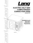
Service Manual for the Lang Models:
EHS-AP, EHS-C, EHS-PP, EHS-PT, & EHS-T
Lang Manufacturing Company
6500 Merrill Creek Parkway
Phone: 1-800-224-5264 Fax: 1-425-349-2733
www.langworld.com
Everett, WA 98203
©Copyright 2000
TABLE OF CONTENTS
PAGE
CHAPTER
1. TABLE OF CONTENTS..........................................................................2
2. READ FIRST...........................................................................................3
3. EQUIPMENT DESCRIPTION .................................................................5
4. INSTALLATION ......................................................................................7
5. START-UP ..............................................................................................8
6. CONTROL PANEL LAYOUT ..................................................................9
7. PROGRAMMING TERMS ......................................................................14
8. PROGRAMMING ....................................................................................15
9. GENERAL OPERATION.........................................................................24
10. TYPICAL OPERATION ..........................................................................26
11. SEQUENCE OF OPERATION................................................................28
12. TROUBLESHOOTING............................................................................31
13. TECHNICAL DATA .................................................................................41
14. WIRING DIAGRAMS ..............................................................................47
15. PARTS LIST ...........................................................................................54
2
IMPORTANT
CAUTION
CAUTION
CAUTION
READ FIRST
IMPORTANT
THE UNIT IS EXTREMELY HEAVY. FOR SAFE HANDLING, INSTALLER
SHOULD OBTAIN HELP AS NEEDED, OR EMPLOY APPROPRIATE
MATERIALS HANDLING EQUIPMENT (SUCH AS A FORKLIFT, DOLLY,
OR PALLET JACK) TO REMOVE THE UNIT FROM THE SKID AND MOVE
IT TO THE PLACE OF INSTALLATION.
ANY STAND, COUNTER OR OTHER DEVICE ON WHICH OVEN WILL BE
LOCATED MUST BE DESIGNED TO SUPPORT THE WEIGHT OF THE
OVEN.
SHIPPING STRAPS ARE UNDER TENSION AND CAN SNAP BACK WHEN
CUT.
DANGER
THIS APPLIANCE MUST BE GROUNDED AT THE TERMINAL PROVIDED.
FAILURE TO GROUND THE APPLIANCE COULD RESULT IN
ELECTROCUTION AND DEATH.
WARNING
INSTALLATION OF THE UNIT MUST BE DONE BY PERSONNEL
QUALIFIED TO WORK WITH ELECTRICITY AND PLUMBING. IMPROPER
INSTALLATION CAN CAUSE INJURY TO PERSONNEL AND/OR DAMAGE
TO EQUIPMENT. UNIT MUST BE INSTALLED IN ACCORDANCE WITH ALL
APPLICABLE CODES.
NOTICE
The data plate is on the back side of the oven above the power cord. The
oven voltage, wattage, serial number, wire size, and clearance
specifications are on the data plate. This information should be carefully
read and understood before proceeding with the installation.
NOTICE
The installation of any components such as a vent hood, grease
extractors, fire extinguisher systems, must conform to their applicable
National, State and locally recognized installation standards.
NOTICE
During the first few hours of operation you may notice a small amount of
smoke coming from the oven, and a faint odor from the smoke. This is
normal for a new oven and will disappear after the first few hours of use.
ALWAYS KEEP THE AREA NEAR THE APPLIANCE FREE FROM
COMBUSTIBLE MATERIALS.
CAUTION
CAUTION
KEEP FLOOR IN FRONT OF EQUIPMENT CLEAN AND DRY. IF SPILLS
OCCUR, CLEAN IMMEDIATELY, TO AVOID THE DANGER OF SLIPS OR
FALLS.
WARNING
KEEP WATER AND SOLUTIONS OUT OF CONTROLS. NEVER SPRAY OR
HOSE CONTROL CONSOLE, ELECTRICAL CONNECTIONS, ETC.
CAUTION
MOST CLEANERS ARE HARMFUL TO THE SKIN, EYES, MUCOUS
MEMBRANES AND CLOTHING. PRECAUTIONS SHOULD BE TAKEN TO
WEAR RUBBER GLOVES, GOGGLES OR FACE SHIELD AND
PROTECTIVE CLOTHING. CAREFULLY READ THE WARNING AND
FOLLOW THE DIRECTIONS ON THE LABEL OF THE CLEANER TO BE
USED.
Never leave a chlorine sanitizer in contact with stainless steel surfaces
longer than 10 minutes. Longer contact can cause corrosion.
NOTICE
3
IMPORTANT
READ FIRST
IMPORTANT
NOTICE
Service on this, or any other, LANG appliance must be performed by
qualified personnel only. Consult your authorized service station directory
or call the factory at 1-800-224-LANG (5264), or WWW.LANGWORLD.COM
For the service station nearest you.
WARNING
BOTH HIGH AND LOW VOLTAGES ARE PRESENT INSIDE THIS APPLIANCE
WHEN THE UNIT IS PLUGGED/WIRED INTO A LIVE RECEPTACLE. BEFORE
REPLACING ANY PARTS, DISCONNECT THE UNIT FROM THE ELECTRIC
POWER SUPPLY.
NOTICE
If an item on the list is followed by an asterisk (*), the work should be done
by a factory authorized service representative.
CAUTION
USE OF ANY REPLACEMENT PARTS OTHER THAN THOSE SUPPLIED BY
LANG OR THEIR AUTHORIZED DISTRIBUTORS CAN CAUSE BODILY
INJURY TO THE OPERATOR AND DAMAGE TO THE EQUIPMENT AND WILL
VOID ALL WARRANTIES.
4
EQUIPMENT DESCRIPTION
Lang Model: EHS Electric Half Size Convention Oven
EXTERIOR
•
•
•
•
The oven exterior dimensions are 30” (76.2 cm) Wide, 25” (63.5 cm) High, 26.5”
(67.31 cm) Deep. The Top, Front, Back, and Sides are constructed of stainless steel
with an aluminized bottom.
The oven door comes standard with a window.
The door handle is constructed of Polycarbinate.
The oven cavity is insulated with high temperature insulation for efficiency and
reduced heat loss.
INTERIOR
•
•
•
The oven cavity dimensions are 15” (38.1 cm) Wide, 20” (50.84 cm) High, 21”
(53.38 cm) Deep.
The oven is designed for five shelves and comes with five Chrome Plated Racks.
The interior of the oven is constructed of stainless steel.
OPERATION
•
•
The EHS oven is a forced air convection oven with a vented oven cavity.
The air is driven by a 1/3 HP fan motor.
CONTROLS
•
The EHS is available either with the Lang Mfg; Accu-Temp (EHS-T) controls,
Accu-Plus (EHS-AP) controls, “Purple” Computer (EHS-C) controls, “Purple-Plus”
Computer (EHS-PP) controls, and “Platinum” Computer (EHS-PT) controls which
include:
•
EHS-T
Easy to use manual control knobs.
Pulse and two speed fan.
•
EHS-AP
Easy to use manual control knobs.
Pulse and two speed fan.
Solid State temperature sensing and controls.
•
EHS-C
Complete Computerized Controls with a Manual Override system.
Programmable up to 10 products with four “tiers” for each program.
Independent Shelf Timers for each Shelf.
Load Control through use of Cooking Curves.
Shelf Compensation Timing for uniform baking.
Single speed fan.
•
EHS-PP
The Purple Plus offer the same great one touch system of the Purple, coupled
with the advanced backing capabilities of the new Platinum.
5
EQUIPMENT DESCRIPTION CONT’D
•
EHS-PT
Icon-driven (touch) panel allows for easy operation, also includes a manual
override system.
Day-Part Memory capabilities allow operators to “recall” the last daily
selections automatically.
Programmable up to 99 products, advanced baking capabilities include: a
12:59:59 timer with ten “tiers”
Independent Shelf Timer for each Shelf.
Load Control through use of Cooking Curves.
Shelf Compensation Timing for uniform baking.
Dual speed fan.
6
INSTALLATION
RECEIVING THE OVEN
Upon receipt, check for freight damage, both visible and concealed. Visible damage should
be noted on the freight bill at the time of delivery and signed by the carrier's agent.
Concealed loss or damage means loss or damage, which does not become apparent until the
merchandise has been unpacked.
If concealed loss or damage is discovered upon unpacking, make a written request for
inspection by the carrier's agent within 15 days of delivery. All packing material should be
kept for inspection.
Do not return damaged merchandise to Lang Manufacturing Company. File your claim
with the carrier.
Prior to un-crating, move the oven as near its intended location as practical. The crating
will help protect the unit from the physical damage normally associated with moving it
through hallways and doorways.
ELECTRICAL CONNECTION
The electrical connection must be made in accordance with local codes or in the absence of
local codes with NFPA No. 70 latest edition (in Canada use: CSA STD. C22.1).
The electrical service entrance is provided by a 1 1/4 inch knock-out at the oven back
directly behind the control compartment. Grounding lugs are provided at the rear service
entrance.
INSTALLING THE LEGS
Legs are available for single, double, and counter top installations. Single deck
installations require a 28-inch leg, double deck installations require a 16-inch leg, and
counter top installations require a 4-inch leg.
To install the 28-inch legs, place some cardboard on the floor and gently tip the oven onto
its back. Fasten two legs to the oven's front. Lift the oven onto its front legs and block the
back up using one of the 28-inch legs set upside down in the center rear of the oven body.
Install the last 28-inch leg onto the oven body on the control side rear. Gently lift the oven
rear, remove the leg set to support the oven center and install it on the last rear corner.
To install the 16-inch legs follow the same instructions as the 28-inch legs.
To install the 4-inch legs, place some cardboard on the floor and gently tip the oven onto its
back. Fasten the four 4-inch legs into the threaded holes provided on the bottom of the
convection oven. Gently lift the oven onto the legs.
STACKING THE OVENS
Remove all the plug buttons from the top of the lower oven.
Remove the stacking kit from the oven compartment of one oven and install the 1 1/4 inch
plastic bushing into the top of the lower oven.
Tip the top oven backwards and install two pins into the front leg holes of the top oven.
Lift the top oven and gently set on top of the lower oven so that the studs nest into the holes
of the lower oven.
7
START-UPS
EHS-C/ EHS-PP/ EHS-PT
Convection Oven Start-Up
1) Verify connections at plug and terminal block
2) Incoming Volt -
Single Phase L1-L2______
Three Phase L1-L2______ L2-L3______ L3-L1______
3) Amp draw
L1______
L2______
L3______
4) Motor amp draw
______
5) Are programs correct?
Yes
No
6) Verify actual temperature at 350 °F
________ °F.
Note:
Install thermocouple wire in center of oven cavity.
Let oven cycle off and on 3 times before recording temperature.
Set oven temperature for 350 °F
Model #_______
Date_______ Serial #________
Store #___________
Tech Name___________________
Contact_______________ Company _________________________
Store Phone #___________ Service Company Phone #______________
Address_____________________
______________________
______________________
8
CONTROL PANEL LAYOUT EHS-T
ON
Power switch.
OFF
PULSE FAN
HI-SPEED
Pulse fan switch. Pulse fan
setting will only turn the fan
on when the oven is calling
for heat.
Dual speed switch.
Toggles the fan between
high and low speed.
FAN
LOW-SPEED
TEMP
Temperature Control. Allows
temperature to be set in 50°F
increments from 100°F.
TIME
Timer Control. Electronic one
hour timer with continuous
beeper.
9
CONTROL PANEL LAYOUT EHS-AP
ON
Power switch.
OFF
PULSE FAN
HI-SPEED
Pulse fan switch. Pulse fan
setting will only turn the fan
on when the oven is calling
for heat.
Dual speed switch.
Toggles the fan between
high and low speed.
FAN
LOW-SPEED
TEMP
Solid State Temperature Control,
Allows temperature to be set in
25°F increments from 140°F.
TIME
Timer Control. Electronic one
hour timer with continuous
beeper.
10
CONTROL PANEL LAYOUT EHS-C
POWER
On
Power switch.
Off
88888
LED Display.
1
6
A
2
7
B
3
8
C
4
9
D
5
0
E
Product Select Button.
Press to select desired
product.
Manual Program Button.
Use when product being
cooked is for one time only.
Man
Prog
Read
Clear
11
Shelf Select Button. Press
to select shelf which
product will be placed.
Read/Clear Button. Used
to read programs, clear
programs, and to access
program menu.
CONTROL PANEL LAYOUT EHS-PP
POWER
On
Power switch.
Off
AlphaNumeric Display.
6
1
Product Select Button.
Press to select desired
product.
Manual Program Button.
Use when product being
cooked is for one time only.
A
2
7
B
3
8
C
4
9
D
5
0
E
Man
Prog
Read
Clear
12
Shelf Select Button. Press
to select shelf which
product will be placed.
Read/Clear Button. Used
to read programs, clear
programs, and to access
program menu.
CONTROL PANEL LAYOUT EHS-PT
Function keys. Keys are
active when a program
option is displayed on
display.
Alpha-Numeric Display.
Cancel button. When
scrolling through menu’s
this will allow you to back
up to the previous menu.
In program mode this will
allow you to advance to the
next step.
Arrow down button.
Allows you to scroll
down.
Power switch.
X
Cancel
Up
Down
Light
On/Off
Arrow up button.
Allows you to scroll
up.
P L A T I M U M
13
PROGRAMMING TERMS
Control Panel Buttons
1 -0
Product Buttons. These are the buttons where the product programs are stored.
Pressing a Product Button will heat the oven to the programmed temperature.
A-E
Shelf Buttons. The control is capable of timing each shelf individually. Pressing a
Product Button then a Shelf Button will start the countdown timer.
Man Prog
The MANUAL PROGRAM button allows the operator to enter a temporary
product program without being required to input the programming code. The
temporary program is erased when the oven is turned off or when a new program is
entered. Time and temperature are the only parameters that can be entered in the
Manual Program mode.
READ/CLEAR
The READ/CLEAR button has several functions.
It is always the first button pressed when entering programming codes.
Pressing it twice then pressing a Product Button will "read-back" the program
in that product button.
Pressing and holding the button down until "88888" appears in the display will
cancel the current mode of the control and return the display to "Enter".
Temp
When the Temperature Recall Button is pressed, the display will indicate the
internal oven temperature. When released the display will revert to the previous
readout.
Programming Terms
COOKING CURVE
Cooking curve is a function of the computer that controls the cooking time. If the
temperature of the oven is lower than the programmed temperature, the control will
slow the timer down to compensate for the lower cooking temperature. Cooking
Curves from 0 - no time adjustment to 7 - maximum adjustment are available.
Cooking Curve 3 is the most commonly used. However, as a general rule the
longer the cooking time the lower the cooking curve, the shorter the cooking time
the higher the cooking curve.
FAN FUNCTION
The convection fan has two programmable options. Fan On (Fan 1) runs the
convection fan continuously. Fan Off (Fan 0) leaves the fan off until heat is called
for by the control. In a convection oven, the fan must come On whenever the heat
comes On. The convection fan can not be turned Off continuously.
TIER
"Tiered" programming is the ability to change the cooking temperature or fan
function during the cooking cycle. As an example, some products require the fan
to be Off for the first half of the cooking cycle then turn On for the last half, Tier 1
would be programmed with the fan in the Off mode then Tier 2 would be fan On.
The Tier lamps located below the display (labeled T1, T2, T3, and T4) will
illuminate to indicate which Tier is being programmed or which Tier the program
is in during the cooking cycle.
14
PROGRAMMING EHS-C
PROGRAMMING
ACTION
DISPLAY
Turn the power switch on. If the oven is already on,
turn it off and then back on.
enter
Quickly enter access code “R/C 1 6 2 7 3 8”. Do
not hold the R/C button.
prod
Select a Product number from 0-9.
St: 00
Select amount of time that product should steam. If
no steam is required press the shelf “A” button to
advance to the next step.
Note: If oven is not strapped for steam convection
then this step will not be provided.
000°F
Select a Temperature from 150°F-450°F.
NOTE: Entering “000” will erase the existing
program.
CC0-7
Fano12
Select the desired cooking curve from 0-7.
Enter a desired Fan setting.
“0” (nofan) Will make the fan pulse with the heat.
“1” (fanonhi) Will make the fan run on high
continuously.
00: 00: 00
“2” (fanonlo) Will make the fan run on low
continuously.
Enter the desired cooking time
(hours:minutes:seconds)
000°f
The program is now entered for a single tier
program, press the “E” button to continue
programming other products. If the program is a
multi tiered program continue by programming the
next tiers. When complete press the “E” button.
prod
When the programs have been completely entered
press the “R/C” button to save and exit the
programming cycle.
enter
15
PROGRAMMING EHS-C CONT’D
EHS-C PROGRAMMING CODES
Below are codes, which will allow you to configure the display or aid in the operation, and
troubleshooting of the oven.
The readout must display "ENTER" before the computer will accept any programming code. If the
readout displays any other word, reset the computer by pressing and holding the “R/C” button until
display reads “88888” then release. Display should now read “ENTER”.
The control allows for a 3-second delay between each button push, if a delay of longer than 3 seconds
has occurred, the programming code must be re-entered.
The instructions call for pressing exactly what is shown under "PRESS".
CODE DESCRIPTION
•
•
•
•
•
PRESS
OPERATIONAL
Recall time remaining on a shelf
Shelf
Cancel a shelf timer
R/C, R/C, Shelf
DISPLAY MODES
Countdown timer display
R/C,4,8,4,8,4,8
Shelf in use display
R/C,0,9,0,9,0,9
Internal oven temperature display
R/C,8,7,8,7,8,7
PROGRAMMING
Enter programming mode
R/C,1,6,2,7,3,8
Recall an existing product program
R/C, R/C, P (Product programmed)
Erase a product program
R/C,1,6,2,7,3,8 (P) (000)
Model identification
R/C, D,C,D,C,D,C
Fan Setting ( HI or Both)
R/C,E,D,C,B,A,1(high),2 (both)
Program download (Contact Factory)
R/C, A, B, C, D, E, P
MAINTENANCE
Actual oven temperature
R/C,3,4,5,6,7,8
Return to ENTER
R/C
SHELF COMPENSATION
Enter shelf compensation mode
R/C, C, B, C, B, C, B
Set shelf compensations
(I.E.) A,2,3,A
Return to ENTER
R/C
16
PROGRAMMING EHS-PP
ACTION
Turn the power switch on. If the oven is already on, press
the Read / Clear key until the following screen is
displayed.
DISPLAY
SELECT PRODUCT OR
READ/CLEAR TO
PROGRAM
XX:XXPM
XXXF
A: SET TIME
B: SET DATE
C: PROGRAM PRODUCTS
D: NEXT MENU
PRODUCT PROGRAM MODE
SELECT PRODUCT
NUMBER 1-9
EDIT PRODUCT?
1=EDIT OR 2=DELETE
NXX TX XXXF CX
XX:XX:XX PXXX F-XX
ENTER COOKING TEMP
100 TO 450 F
NOX
T1
XXXF
ENTER COOKING TIME
HR:MIN:SEC
NOX T1 XXXF CO
ENTER COOKING CURVE
0 TO 100%
NOX T1 XXXF CXX
XX:XX:XX PXXX F-XX
ENTER FAN SPEED
1=HI
2=LOW
NOX T1 XXXF CXX
XX:XX:XX PXXX F-XX
ENTER FAN PULSE RATE
1 TO 100%
NOX T1 XXXF CXX
XX:XX:XX PXX F-XX
CONTINUE TO TIER 2
1=YES 2=NO
NOX T1 XXXF CXX
XX:XX:XX PXXX F-XX
Enter access code “1 6 2 7 3 8”.
Select “C”.
Select a number from 0-9 and press the key corresponding
to that number.
If a product Key selected already has a program, the screen
will read.
Enter a desired cooking / baking temperature. The screen
will automatically advance to the next display.
Enter the cooking time and then press “E” to advance to
the next screen.
Enter the desired cooking curve. (Refer to sections 6.3 and
6.7 for more detail)
Select Fan speed. (Hi=1700 rpm, Low=1400)
Select Fan Pulse rate. (0 to 100%). 0=off unless calling for
heat. 100=on at all time.
NOTE: Any number between 0-100 means that the fan
will be on that many number of seconds in a 100-second
block. (E.g. 67%= on for 67 seconds in a 100 second
block)
If your press 1 you will go through the same sequence as
outlined above. If you press 2 the next display will
automatically appear.
A:
B:
C:
D:
17
SET TIME
SET DATE
PROGRAM PRODUCTS
NEXT MENU
PROGRAMMING EHS-PT
ACTION
DISPLAY
Step 1. Turn the power switch on. If the oven is
already on, press the “CANCEL” key until
the following screen is displayed.
Step 2. Select:
RUN OVEN
TIME / DATE / PROGRAM.
TIME / DATE / PROGRAM
TIME
12:00
DATE
01/01/01
ACTION
TEMP
325
STATUS
STANDBY
DISPLAY
DISPLAY PRODUCT
TIMER ONLY
Step 3. Select :
SET TIME / DATE
PROGRAM COMPUTER
PROGRAM COMPUTER
TIME
12:00
DATE
01/01/01
ACTION
TEMP
325
DISPLAY
ENTER ACCESS CODE
Step 4. Using the and arrows, enter access
code “A B C D E F”
A
Press or to scroll through letters and numbers,
then select “ENTER” to move the cursor to the right.
USE
KEYS TO SELECT
THEN PRESS ENTER
EXAMPLE: Press once for an “A”, then press
“ENTER”. Press twice for a “B”, then
select “ENTER”. Continue through “F”.
The screen will then automatically
advance once access code has been
entered correctly.
ENTER
PRESS CANCEL TO QUIT
18
STATUS
PROGRAM
PROGRAMMING EHS-PT CONT’D
ACTION
DISPLAY
Step 5. Select:
PROGRAM PRODUCTS
EDIT READY ZONE
PROGRAM PRODUCTS
EDIT ACCESS CODE
ENABLE MANUAL PRODUCT
CONFIGURE TIME OF DAY
ACTION
DISPLAY
Step 6. Select:
CREATE NEW PRODUCT
EDIT PRODUCT
CREATE NEW PRODUCT
DELETE PRODUCT
EDIT PRODUCT
ACTION
DISPLAY
Step 7. “SELECT PRODUCT ICON” is the first
screen when creating a product program.
Press until you find an icon that best
resembles your product. If necessary, press
to go backward through the icon list.
Select “ENTER” to accept the icon, and more
to the next screen
SELECT PRODUCT ICON
USE
KEYS TO SELECT
THEN PRESS ENTER TO ACCEPT
APPETIZER A
ENTER
19
PROGRAMMING EHS-PT CONT’D
ACTION
DISPLAY
Step 8. “SELECT PRODUCT NAME” is where you
spell the name using the or to select
each letter. Then select “ENTER” to move
the cursor to the next space and select a new
letter.
NOTE: “APPETIZER A” is the name that must be
replaced with the new product name or blanks, when
the product name is shorter than “APPETIZER A”.
SELECT PRODUCT NAME
APPETIZER A
USE
KEYS TO SELECT
APPETIZER A
EXAMPLE: “APPLE” replaces only APPET, IZER A
must be replace by blanks. A blank can
be found before “A” or after “9” when
scrolling.
ACCEPT
ENTER
ACTION
DISPLAY
Step 9. “SELECT PRODUCT TEMPERATURE”
Press the
or to select a number. Then
select “ENTER” to move the cursor to the
next space and select a new number. The
screen will automatically advance after you
enter the last number.
SELECT PRODUCT TEMPERATURE
100
EXAMPLE: (320) Press three times for a “3”, then
select “ENTER” to advance the cursor.
Press two times for a “2”, then select
“ENTER” to advance the cursor. Since
“0” is already displayed just select
“ENTER” to advance to the next screen.
USE
KEYS TO SELECT
APPLE
TIER 1
ACCEPT
ENTER
ACTION
DISPLAY
Step 10. “SELECT TIER COOK TIME”. Time is
entered in hours:minutes:seconds. The
maximum is 12:59:59. Select “ENTER” to
advance cursor to the place you want to
enter a number.
EXAMPLE: (45 minutes:00 seconds) Select “ENTER”
twice to advance from hours to minutes,
then press four times for a “4”, then
select “ENTER” to advance the cursor.
Then press five times for a “5”, then
select “ENTER” to advance the cursor.
Since “0” is the next two numbers simply
select “ENTER” again twice to advance
the cursor.
SELECT TIER COOK TIME
00:45:00
USE
APPLE
TIER 1
TEMP:
ACCEPT
ENTER
20
320F
KEYS TO SELECT
PROGRAMMING EHS-PT CONT’D
ACTION
DISPLAY
Step 11. “SELECT COOKING CURVE”. Press or
to select numbers, select “ENTER” to
move the cursor to the next space. Cooking
curve may be any number between 0% and
100%.
SELECT COOKING CURVE
000 %
USE
EXAMPLE: (80%) Select “ENTER” once to advance
the cursor one space, then press eight
times for a “8”. Select “ENTER to
advance the cursor. Since “0” is the next
number, select “ENTER” to advance to
the next screen.
KEYS TO SELECT
APPLE
TIER 1
TEMP:
320F
TIME:
00:45:00
ACCEPT
ENTER
ACTION
Step 12. “SELECT FAN SPEED”. The cursor will
automatically appear under HIGH, that is
your default setting. Press “ENTER or
ACCEPT” to keep high fan and advance to
the next screen. If LOW is the correct
setting press the or to move the cursor
to low. Once low is selected, select “ENTER
or ACCEPT” to move to the next screen.
DISPLAY
SELECT FAN SPEED
HIGH
LOW
USE
KEYS TO SELECT
APPLE
TIER 1
TEMP:
320F
COOKING CURVE:
ACCEPT
ENTER
21
TIME:
80 %
00:45:00
PROGRAMMING EHS-PT CONT’D
ACTION
DISPLAY
Step 13. “SELECT PULSE RATE”. Press or to
select numbers, select “ENTER” to move the
cursor to the next space. 100% is the
default. If this okay, select “ENTER” three
times or “ACCEPT” once to advance to the
next screen.
SELECT PULE RATE
100 %
EXAMPLE: (80%) Press the once for “0”. Select
“ENTER” once to advance the cursor one
space, then press eight times for a “8”.
Select “ENTER to advance the cursor.
Since “0” is the next number, select
“ENTER” to advance to the next screen.
USE
KEYS TO SELECT
APPLE
TIER 1
TEMP: 320F
FAN: HI
COOKING CURVE:
TIME:
00:45:00
80 %
ACCEPT
ENTER
ACTION
Step 14. “CORRECT”. The cursor automatically
appears on “YES”. The computer is asking
if the program displayed is correct. If any
part of that program is incorrect, press or
till the cursor is on “NO”. Select “ENTER”
or “ACCEPT”. This will return you to step 7.
Selecting “YES” will advance the
sceen.“NO”.
DISPLAY
CORRECT?
YES
NO
USE
KEYS TO SELECT
APPLE
TIER 1
TEMP: 320F
FAN: HI
COOKING CURVE:
ACCEPT
ENTER
22
TIME:
RATE:
80 %
00:45:00
100 %
PROGRAMMING EHS-PT CONT’D
ACTION
Step 15. “CONTINUE TO NEXT TIER”. The cursor
automatically appears on “NO”. Select
“ENTER” or “ACCEPT” to end programming
or move the cursor with the or to
“YES”. This will allow you to enter another
tier to this program. Repeat steps 6-14 to
program second tier.
DISPLAY
CONTINUE TO NEXT TIER
YES
NO
USE
KEYS TO SELECT
APPLE
TIER 1
TEMP: 320F
FAN: HI
COOKING CURVE:
TIME:
RATE:
00:45:00
100 %
80 %
ACCEPT
ENTER
ACTION
DISPLAY
Step 16. After programming the last tier, select “NO”
when asked “CONTINUE TO NEXT TIER”
the computer will automatically advance the
screen to program more products. If no
other products need to be programmed,
select “CANCEL” three times to advance
screen to the boot up screen.
CREATE NEW PRODUCT
EDIT PRODUCT
DELETE PRODUCT
EDIT PRODUCT
ACTION
DISPLAY
Step 17. You may now preheat the oven for any
products you have programmed.
Step 18. Select:
RUN OVEN
Run oven
TIME / DATE / PROGRAM
23
TIME
DATE
TEMP
STATUS
12:00
01/01/01
325
STANDBY
GENERAL
OPERATIONS
Convection ovens constantly circulate air over the product. This strips away the thin
layer of moisture and cool air from the top of the product. Heat penetrates more
quickly. Cooking times are shortened and cooking temperatures are usually reduced.
To convert standard deck oven recipes to convection oven recipes, reduce the
temperature 50 °F and the time by 25%. Make adjustments as necessary, depending
upon your results.
The lower the temperature the more even the bake.
Check the product halfway through the baking cycle. Look through the door windows.
Opening the oven door is not recommended.
If products are brown on the outside and not done on the inside, too high a temperature
is being used. Decrease the temperature 15-25 °F.
If products are pulling to the edge of pans or spilling, the oven is not leveled or the
pans are warped. Correct as necessary.
Load each shelf evenly. Spaces should be maintained equally between the pan and
walls. Front and back. This will allow an even distribution of airflow.
BAKING
Most baking should be done with the vent closed. Open the vent only with high
moisture products to avoid seepage around the front of the door.
Always weigh your product. This will give you a more consistent size, color and
quality.
Center the pan in the oven. The better the air flow around the product, the better the
bake.
The convection oven is a mechanical piece of equipment. The same control settings
will always give the same results. If the results vary, problems may be because of
preparation, not the oven.
LOADING
Place product as close to oven as practical. Open oven doors and load quickly but
carefully.
If only one pan is required, load on center shelf. If two pans are required, load on
second and fourth shelf. If three pans are required, load on top shelf, bottom shelf, and
center shelf. If four pans are required, load on top shelf, bottom shelf, and middle two
shelves. If five shelves are required, space evenly in oven. (See page 27 for more
detail)
UNLOADING
It is a characteristic of all convection ovens to unload the top shelf before the bottom
shelves. The rising of heat and the hot oven ceiling causes the top shelf to bake
quicker. This characteristic is more pronounced when baking at higher temperatures
and/or for prolonged periods of time.
24
GENERAL CONT’D
ONE PAN
TWO PAN
THREE PAN
FOUR PAN
FIVE PAN
25
TYPICAL OPERATION
EHS-T TYPICAL OPERATION SEQUENCE
ACTION
RESULT
Turn power switch to ON.
Adjust proper temperature, between 140 & 450
degrees and allow to preheat up to 20 minutes.
Oven begins heating.
Open oven doors and insert product, set timer up to
60 minutes.
Timer begins counting down.
Timer beeps continuously when done.
Product should now be done.
EHS-AP TYPICAL OPERATION SEQUENCE
ACTION
RESULT
Turn power switch to ON.
Control panel heat call light comes on.
Adjust proper temperature, between 140 & 450
degrees and allow to preheat up to 20 minutes.
Oven begins heating.
Open oven doors and insert product, set timer up to
60 minutes.
Timer begins counting down.
Timer beeps continuously when done.
Product should now be done.
EHS-C TYPICAL OPERATION SEQUENCE
ACTION
RESULT
Turn power switch to ON.
Control panel comes on, display says “88888” and
then “ENTER”, motor starts.
Press a product button.
Display says “PREHT” (Preheat), oven begins to heat
to the programmed temperature.
Beeper sounds briefly.
Display says “READY”.
Open the oven doors and load the product. Close the
door and press the product button again.
Beeper sounds briefly and display says “SHELF”.
Press the shelf button(s) which correspond to the
shelf positions which the product is loaded (A
equals the top shelf and E equals the bottom shelf).
Display shows a countdown timer and begins to
count toward zero.
Beeper sounds continuously.
Display shows “DONE”, shelf button(s) flash.
Press the flashing shelf button(s).
Beeper stops. Display shows “READY” if no other
shelves carry product or resume count down for
shelves that still have product cooking.
Open oven door and remove the product, which
corresponds to flashing shelf button(s).
26
TYPICAL OPERATION CONT’D
EHS-PT TYPICAL OPERATION SEQUENCE
ACTION
RESULT
Press the on switch.
Control panel comes on, display says “LANG, Run
Oven, Time Date Program.
Select “Run Oven”.
Display will show a list of product to choose.
Select Product button next to Icon desired.
Display says “Preheating to XXXF”.
Beeper sounds briefly.
Display says “Ready”.
Select Product to start.
Display shows possible product selection for that
temperature.
Select Product to start.
Display says “Select shelf”.
Press Product button next to desired shelf.
Display will show icon chosen and begin to count
down.
Beeper sounds continuously.
Display shows “ DONE” press button and remove
product from that shelf.
Oven is ready for another product.
EHS-PP TYPICAL OPERATION SEQUENCE
ACTION
RESULT
Turn power switch to ON.
Control panel comes on, display says “SELECT
PRODUCT OR READ/CLEAR TO PROGRAM.
Press a product button.
Display says “PRODUCT X PREHEATING TO
XXX F”. Motor starts and oven begins preheating
to the programmed temperature.
Beeper sounds briefly.
Display says “READY SELECT PRODUCT TO
START ”.
Open the oven doors and load the product. Close
the door and press the product button again.
Beeper sounds briefly and display says “SELECT
OVEN SHELVES PRODUCT X”.
Press the shelf button(s) which correspond to the
shelf positions just left, which the product is loaded
(A equals the top shelf and E equals the bottom
shelf).
Display shows a countdown timer and begins to
count toward zero.
Beeper sounds continuously.
Display shows “DONE PRESS SHELF BUTTON
X, REMOVE PRODUCT”, shelf button(s) flash.
Press the flashing shelf button(s).
Beeper stops. Display shows “READY SELECT
PRODUCT TO START” if no other shelves carry
product or resume count down for shelves that still
have product cooking.
Open oven door and remove the product, which
corresponds to flashing shelf button(s).
27
SEQUENCE OF OPERATION EHS-T
Power switch turned on.
240/208 VAC across Common terminals on power switch and “B” terminal of 12 pin Terminal block.
240/208 VAC to Common terminals of Motor relay.
240/24-volt transformer energized.
24 VAC across “C” and “D” (common) of 24 pin Terminal block.
24 VAC across coil of Motor relay. (Through door switch)
24 VAC across “D” and of Heat contactor. (Through door switch and high limit thermostat)
24 VAC across “D” and terminal on thermostat.
Motor contactor closes.
Motor starts.
24 VAC across coil of Heat contactor.
Heat contactor closes.
208/240 volts to elements.
Oven heats.
SEQUENCE OF OPERATION EHS-AP
Power switch turned on.
240/208 VAC across Common terminals on power switch and “B” terminal of 12 pin Terminal block.
240/208 VAC to Common terminals of Motor relay.
240/24-volt transformer energized.
24 VAC across “C” and “D” (common) of 24 pin Terminal block.
24 VAC across coil of Motor relay. (Through door switch)
24 VAC across “D” and of Heat contactor. (Through door switch and high limit thermostat)
24 VAC across “D” and Heat output on board.
Motor contactor closes.
Motor starts.
24 VAC across coil of Heat contactor.
Heat contactor closes.
208/240 volts to elements.
Oven heats.
28
SEQUENCE OF OPERATION EHS-C
Power switch turned on.
240/208 VAC across Common terminals on power switch and “A” terminal of 24 pin. Terminal block.
240/208 VAC across any “A” and “B” terminal of 24 pin Terminal block.
240/208 VAC to Common terminals of Motor relay.
240/208 VAC across common terminals of Back-up toggle switch.
120 VAC to coil of Back-up relay.
240/24 volt transformer energized.
24 VAC across “C” and “D” (common) of 24 pin Terminal block.
24 VAC across “D” and coil of Motor relay.(Through door switch)
24 VAC across “D” and of Heat contactor. (Through door switch and high limit thermostat)
24 VAC across “D” and Common terminals of Back-up relay.
240/12 volt transformer energized.
Back-up toggle switch Off.
24 VAC across “D” and TP4, TP5 and TP6.
12 volts to TP1 on microprocessor.
24 VAC across coil of motor contactor.
Motor contactor closes.
240/208 VAC across NO (Normally open) contacts of Motor relay.
Motor starts.
24 VAC across coil of Heat contactor.
Heat contactor closes.
208/240 volts to elements.
Oven heats.
Back-up toggle switch Off.
208/240 VAC across coil of Back-up relay.
Back-up relay closes.
24 VAC across and Back-up Thermostat (With door switch energized.)
24 VAC across coil of Motor relay.
Motor contactor closes.
240/208 VAC across NO (Normally open) contacts of Motor relay.
Motor starts.
Temperature set on back up thermostat.
24 VAC across “D” and each terminal of back-up thermostat.
24 VAC across coil of Heat contactor.
Heat contactor closes.
208/240 volts to elements.
29
SEQUENCE OF OPERATION EHS-PP/PT
Oven plugged in.
208/240 VAC across any “A” and “B” terminal on the terminal block.
208/240 VAC to Control transformer (208-240VAC / 24-12 VAC) and Component transformer
240VAC / 24VAC.
Transformers energize.
24 VAC to any “C” and “D” terminal on the terminal block.
24 / 12 VAC to Circuit Board (JP40).
24 VAC to Circuit Board outputs (JP11- JP13).
Power Switched turned to “ON”.
Display comes on.
Product selected.
24 VAC across motor output (JP12) and “D”.
24 VAC across motor HI relay coil.
Motor relay closes.
208/240 VAC to motor.
Motor Starts.
24 VAC across heat output (JP11) and “D”.
24 VAC across heat contactor (through over-temperature thermostat).
Heat contactor closes.
208/240 VAC to elements.
Back up toggle switch to “ON” .
208/240 VAC across coil of back up relay coil.
Back up relay energizes.
24 VAC to motor relay.
Motor relay energizes.
208/240 VAC to motor.
Motor Starts.
24 VAC to thermostat.
Temperature set on thermostat.
24 VAC to heat contactor.
Contactor energizes.
208/240 VAC to elements.
30
TROUBLESHOOTING EHS-T
HINT: Confirm that all Circuit Breakers are in the “ON” position.
NO MOTOR
PROBABLE CAUSE
CORRECTIVE ACTION
Defective Fan Switch
Verify that Fan switch is in “ON” position (In pulse position motor
will only cycle when oven calls for heat).
Defective Transformer
Check transformer for normal operation.
Defective Motor Relay
Check motor relay for normal operation. (24VAC 35 Ω)
Defective Door Switch
Check door switch for normal operation.
Defective Motor
Check motor for normal operation. (P1-T9 low, P1-T7/T4 high)
NO HEAT
PROBABLE CAUSE
CORRECTIVE ACTION
Defective Elements
Check that elements are getting power.
Confirm that Elements are working correctly. (See Technical Data)
Defective Transformer
Check transformer for normal operation.
Replace if necessary.
Defective Heat Contactor
Confirm that Contactor is getting correct voltage.
Confirm that Contactor is operating properly. (24VAC 6Ω)
Defective Thermostat
Confirm that Thermostat is getting 24 VAC. Measure between
Thermostat terminal and “D” on the terminal block
If voltage is not present:
Check Transformer for normal operation.
If voltage is present:
Check thermostat for continuity.
Replace as necessary
31
TROUBLESHOOTING EHS-AP
HINT: Confirm that all Circuit Breakers are in the “ON” position.
NO MOTOR
PROBABLE CAUSE
CORRECTIVE ACTION
Defective Fan Switch
Verify that Fan switch is in “ON” position (In pulse position motor
will only cycle when oven calls for heat).
Defective Transformer
Check transformer for normal operation.
Defective Motor Relay
Check motor relay for normal operation. (24VAC 35 Ω)
Defective Door Switch
Check door switch for normal operation.
Defective Motor
Check motor for normal operation. (P1-T9 low, P1-T7/T4 high)
NO HEAT
PROBABLE CAUSE
CORRECTIVE ACTION
Defective Elements
Check that elements are getting power.
Confirm that Elements are working correctly. (See Technical Data)
Defective Transformer
Check transformer for normal operation.
Replace if necessary.
Defective Probe
Confirm that probe has proper resistance for the correct temp. (See
Technical Data)
Defective Heat Contactor
Confirm that Contactor is getting correct voltage.
Confirm that Contactor is operating properly. (24VAC 6Ω)
Defective Thermostat
Confirm that Heat Call light is on.
If no light is detected:
Check 12-position switch for normal operation. (See Technical Data)
If light is detected:
Check for 24VAC across heat output and “D” on 12 Pole terminal.
If voltage is not present:
Replace Circuit board.
If voltage is present:
Check over temperature thermostat for proper operation.
Check door switch for normal operation.
32
TROUBLESHOOTING EHS-C
To help troubleshoot the oven you should perform the following “Manual Override” test:
Open drop down door located on the lower right side, directly below front panel.
Turn back up toggle (on/off) switch to “on” position.
Turn main power switch to “on” position.
Check oven for normal operation.
If fan comes on and unit heats up refer to section 4.1 ( NO DISPLAY ).
If fan does not come on refer to section 4.2 ( NO FAN ).
NO DISPLAY
PROBABLE CAUSE
CORRECTIVE ACTION
Power switch is not turned on
Turn power switch on.
Defective power switch
Check power switch for normal operation. Replace as necessary.
Defective back-up relay
Check relay for normal operation.
Check coil for 24 VAC.
If 24 VAC is measured. Turn oven off and:
Check coil for 7.2 KΩ.
Replace as necessary.
If 24 VAC is not measured.
Verify that manual override switch is in “off” position.
Check manual override switch for normal operation.
Check wires for any shorts.
Defective control transformer
(12 VAC).
Check transformer for normal operation.
Check primary coil for 208/240 VAC and 630 Ω. Check secondary
coil for no less than 10.5 VAC and 1 Ω.
If voltage is measured on primary:
Check for voltage on secondary.
Replace transformer.
If voltage is not measured on primary:
Check wires for any shorts.
Defective rectifier
Check for no less than 10.5 VAC on TP1 and 5 VDC on TP2.
If correct voltage is present at TP1 and present, but low at TP2
unplug both ribbon connections from CPU and re-measure at TP2.
If voltage remains low at TP2 replace CPU (40102-311).
If voltage at TP2 increased to 5 VDC when ribbon was unplugged,
plug ribbon back in to CPU and disconnect from Interface board.
Re-measure at TP2.
If voltage dropped to below 5 VDC replace ribbon cable (31110-01).
If voltage remains at 5 VDC, plug ribbon back into Interface board
and measure for 5 VDC at TP3.
If voltage is present at TP3 and display is still not on, press and hold
the R/C button on board if LED’s come on replace Interface board.
If LED segment does not illuminate or the LED is blank, replace
LED.
33
TROUBLESHOOTING EHS-C CONT’D
NO FAN-Manual Mode
PROBABLE CAUSE
Defective 240/24 VAC
transformer
CORRECTIVE ACTION
Check for 24 VAC on “C” and “D” of the terminal block.
If 24 VAC is not measured: Turn off and:
Check secondary coil for 1 Ω.
Check primary coil for 77 Ω.
Replace transformer.
If 24 VAC is measured: Turn off and:
Check back-up relay for normal operation.
Back-up relay not energizing
Check for 240 VAC on relay coil.
If 240 VAC is measured: Turn unit off and:
Check back-up relay coil for 7.2 K Ω.
Replace if defective.
If 240 VAC is not measured:
Check back-up switch (SPDT) for normal operation.
Replace if defective.
Motor contactor not energized
Check for 24 VAC at contactor or relay coil.
If 24 VAC is not measured: Turn oven off and:
Check door switch for normal operation.
Check door switch for continuity.
Replace or adjust door switch.
If 24 VAC is measured: Turn unit off and:
Check contactor coil for continuity.
Replace if defective.
No voltage across contactor
points
Check 208/240 VAC across “C” terminals of contactor.
If 208/240 VAC is not measured:
Check connection to main contactor (heat contactor).
Check circuit breaker.
If 208/240 VAC is measured:
Check across “NO” contacts. Should have 208/240 VAC.
Replace if defective.
NO MOTOR COMPUTER MODE
PROBABLE CAUSE
No 24 VAC on Interface board
CORRECTIVE ACTION
Check for 24 VAC at TP4 to common (“D”).
If 24 VAC is not measured:
Check for 24 VAC at “NC” contacts on back-up relay.
If 24 VAC is measured:
Check for 24 VAC at TP5.
Replace Interface board if defective.
34
TROUBLESHOOTING EHS-C CONT’D
NO HEAT Manual Mode
NOTE: Fan must be operating before trouble shooting No heat.
PROBABLE CAUSE
Back-up relay not energizing
CORRECTIVE ACTION
Check for 240 VAC on relay coil.
If 240 VAC is measured. Turn unit off and:
Check back-up relay coil for 7.2 Ω.
Check “NO” contacts for 24 VAC.
Replace if defective.
If 240 VAC is not measured:
Check back-up switch (SPDT) for normal operation.
Replace if defective.
Defective thermostat
Turn unit off and check for continuity while cycling thermostat on
and off.
Replace if defective.
Defective contactor
Check for 24 VAC at heater coil.
If 24 VAC is measured. Turn oven off and:
Check for continuity through coil.
Replace if defective.
If 24 VAC is not measured. Turn oven off and:
Check for continuity through hi-temp wires going to over-temp
thermostat.
Replace over-temp thermostat if defective.
Defective elements
Check elements for continuity.
Replace if defective.
Defective over-temp thermostat
Check for 24 VAC on #55 red wire to common “D”.
If 24 VAC is not measured: Turn oven off and:
Check for continuity through over-temp thermostat.
Replace if defective.
NO HEAT Computer Mode
PROBABLE CAUSE
No 24 VAC on Interface board
CORRECTIVE ACTION
Check for 24 VAC at TP4 to ground.
If 24 VAC is not measured:
Check for 24 VAC at “NC” contacts on back-up relay.
If 24 VAC is measured:
Check for 24 VAC at TP6.
Replace Interface board if defective.
35
TROUBLESHOOTING EHS-C CONT’D
DISPLAY LOCKS UP
PROBABLE CAUSE
CORRECTIVE ACTION
“Help” in display
Check probe for proper resistance.
Check that probe connections are secure.
Push “TEMP” button on control board and check to see if temperature
rapidly descends. If temp does descend rapidly, replace ribbon cable.
Check to see that contactors/relays are not stuck in the closed
position.
Replace contactor if defective.
Check for foreign objects keeping contactor closed.
“88888” stuck in display
Check for stuck button by pressing any button.
If computer beeps or chirps:
Check control panel transformer (12 VAC) for proper operation.
Check TP1 for at least 10.5 VAC.
Check TP2 for at least 4.99 VDC.
Check TP3 for at least 4.97 VDC.
If computer does not beep or chirp:
Check each button for movement.
Check that panel label has not been damaged in any way.
Replace button if defective.
Replace panel label.
Display has shelf “A”
Read Programming Codes.
36
TROUBLESHOOTING EHS-PP / -PT
To help troubleshoot the oven you should perform the following “Manual Override” test:
Open drop down door located on the lower right side, directly below front panel.
Turn back up toggle (on/off) switch to “on” position.
Turn main power switch to “on” position.
Check oven for normal operation.
NO DISPLAY
PROBABLE CAUSE
CORRECTIVE ACTION
Defective Power Switch (-PP
only)
Confirm that toggle switch is getting correct voltage.
Check power switch for normal operation.
Defective Power Switch
output on circuit board
(JP37)
Confirm that JP37 has 5VDC in the off position and nominal voltage
in the on position.
If JP37 has a constant 5VDC check toggle switch for normal
operation.
Defective Control
Transformer
Confirm that 208/240VAC is feeding primary coil.
Confirm that 24VAC and 12VAC is at JP40 (24VAC across solid
yellow wires and 12VAC from one solid yellow wire to yellow with
red stripe).
Defective Display
Check ribbon cable connections.
Confirm that voltage is present at JP40.
If no voltage is present:
Replace control transformer.
If voltage is present:
Confirm that CPU has 5VDC at TP1 (this means that the CPU is
getting correct voltage).
Confirm that CPU has 12VDC at TP2 (this means that the CPU is
sending out the correct voltage).
If no voltage is present:
Replace CPU.
If voltage is present:
Replace display.
IMPORTANT NOTICE: Power must be disconnected at source when disconnecting any ribbon cable or any
connector from CPU or Display. Failure to do so will result in damage to the Display board and CPU.
37
TROUBLESHOOTING EHS-PP / -PT CONT’D
NO MOTOR, MANUAL MODE
PROBABLE CAUSE
CORRECTIVE ACTION
Defective back-up toggle
switch
Confirm that toggle switch is in the “ON” position.
Check toggle switch for normal operation.
Defective back-up relay
Check for 208/240VAC at relay coil.
If no voltage is present:
Confirm that points are making.
If voltage is present:
Replace relay.
Defective component
transformer
Confirm that 208/240VAC is feeding primary coil.
Confirm that 24VAC is at secondary coil.
Defective motor relay
Check for 24VAC at relay coil.
If no voltage is present:
Confirm that points are making.
If voltage is present:
Replace relay.
Check for 208/240VAC across P1 and T7/T4.
Defective motor
If no voltage is present:
Confirm that wires have continuity.
If voltage is present:
Replace motor.
NO MOTOR, COMPUTER MODE
IMPORTANT NOTICE: Before trying to trouble shoot “No Motor in Computer Mode” confirm that motor is
operational in “Manual Mode”.
PROBABLE CAUSE
Defective output on CPU
board
CORRECTIVE ACTION
Check for 24VAC at JP12 for high or JP13 for low (while oven is
calling for heat).
If no voltage is present:
Board is operating correctly.
If voltage is present:
Replace CPU.
38
TROUBLESHOOTING EHS-PP / -PT CONT’D
NO HEAT, MANUAL MODE
PROBABLE CAUSE
CORRECTIVE ACTION
Defective back-up toggle
switch
Confirm that toggle switch is in the “ON” position.
Defective back-up relay
Check for 208/240VAC at relay coil.
Check toggle switch for normal operation.
If no voltage is present:
Confirm that points are making.
If voltage is present:
Replace relay.
Defective component
transformer
Confirm that 208/240VAC is feeding primary coil.
Defective Thermostat
Confirm that thermostat has 24VAC.
Confirm that 24VAC is at secondary coil.
If no voltage is present
Check component transformer and wiring for normal operation.
If voltage is present
Check thermostat for normal operation. Replace as necessary.
Defective heat contactor
Check for 24VAC at relay coil.
If no voltage is present:
Confirm that points are making.
If voltage is present:
Replace contactor.
Defective elements
Check for 208/240VAC across elements.
If no voltage is present:
Confirm that wires have continuity.
If voltage is present:
Replace elements.
NO HEAT, COMPUTER MODE
IMPORTANT NOTICE: Before trying to trouble shoot “No Heat in Computer Mode” confirm that the oven heats in
“Manual Mode”.
PROBABLE CAUSE
Defective output on CPU
board
CORRECTIVE ACTION
Check for 24VAC at JP11 (while oven is calling for heat).
If no voltage is present:
Board is operating correctly.
If voltage is present:
Replace CPU.
39
TROUBLESHOOTING EHS-PP / -PT CONT’D
ANOMALIES
PROBABLE CAUSE
Display will intermittently
blank out
CORRECTIVE ACTION
Check ribbon cable for good connections
Check panel label buttons and confirm that none of the domes are
collapsed.
If domes are collapsed:
Replace panel label.
Intermittently over heats or
under cooks
Check probe for proper resistance.
Check ribbon connection for good connection.
Check probe for good connection.
40
TECHNICAL DATA
ELEMENT RESISTANCE
208 Volt
17 Ω
240 Volt
23 Ω
480 Volt
60 Ω
TRANSFORMER RESISTANCE
TRANSFORMER
Input
Primary
Secondary
Output
208/24 Volt
208/240 Volt
77 Ω
1Ω
24 Volt
240/12 Volt
208/240 Volt
630 Ω
1Ω
12 Volt
208/240-24/12
208/240 Volt
208V
64 Ω
240V
75Ω
12V
.6Ω
24V
1Ω
24/12 Volts
CONTACTOR RESISTANCE
CONTACTOR
Coil
3 Pole 24 Volt coil
6Ω
2 Pole 24 Volt coil (P & B) (PP & PT motor)
35 Ω
RELAY RESISTANCE
RELAY
Coil
240 VAC
7.2 KΩ
OVER-TEMP THERMOSTAT
OVER-TEMP
Wires #21 and #17
Normally closed
DOOR SWITCH
Check switch between “COM” (common) and “NO” (normally open) contacts, insure switch closes approximately 3 to 4
inches before door closes.
BLOWER FAN
Blower fan will rotate clockwise and should have a 5/8“ gap between it and the back wall of the can.
41
TECHNICAL DATA CONT’D
AUTO/BYPASS SWITCH
The Auto / Bypass and Energy switch are located below the controls behind a pull down access panel.
•
Auto/Bypass switch
Normally in “OFF”. The “ON” position will interrupt
power to the computer and allow use of the back-up
thermostat.
•
Energy switch
Normally in “HIGH” for 11 kW heats. “LOW” WILL
PROVIDE 8.25 kW heat. Not provided on Steam
convection ovens.
LINE AMPERAGE, WATTAGE, AND PROPER PHASING
MODEL
EHS
KW per
connection
7.8
Nominal Amps Per Line
Three Phase
208 Volt
240 Volt
L1
L2
L3
L1
L2
23.3
20.8
23.3
20.2
18
Single Phase
L3
20.2
208 V
38.9
240 V
33.8
PHASING
L1
1,4
THREE PHASE
L2
2,5
SINGLE PHASE
L3
3,6
L1
1,3,5
EHS–PT / PP COOKING CURVE CONVERSION
Old Style Purple
0
1
2
3
4
5
6
7
New Style Platinum / Purple Plus
0%
17%
26%
40%
50%
56%
63%
71%
42
L2
2,4,6
TECHNICAL DATA CONT’D
PROBE RESISTANCE
TEMP
RESISTANCE
VOLT DROP
70
556
1.11
80
569
90
TEMP
RESISTANCE
VOLT DROP
290
881
1.76
1.14
300
897
1.79
583
1.17
310
914
1.83
100
596
1.19
320
931
1.86
110
610
1.22
330
948
1.90
120
623
1.25
340
965
1.93
130
637
1.27
350
983
1.97
140
651
1.3
360
1000
2.00
150
665
1.33
370
1018
2.04
160
678
1.36
380
1036
2.07
170
694
1.39
390
1054
2.11
180
709
1.42
400
1072
2.14
190
724
1.45
410
1090
2.18
200
739
1.48
420
1109
2.22
210
754
1.51
430
1127
2.25
220
769
1.54
440
1146
2.29
230
785
1.57
450
1165
2.33
240
800
1.60
460
1184
2.37
250
816
1.63
470
1204
2.41
260
832
1.66
480
1223
2.45
270
848
1.70
490
1243
2.49
280
864
1.73
500
1263
2.53
NOTE
Probe is factory checked at 350 °F. Must be completely disconnected from circuit board when measuring
probe resistance. Display will read “HELP” if probe is open or unplugged. Any probe resistance can be
multiplied by 2 milli-amps (.002) to determine voltage drop.
43
TECHNICAL DATA CONT’D
EHS-C MODEL STRAPPING
The Front Control panel of the Lang “Purple” computer must be configured to match the model of oven it is being installed
in. To configure the front control panel, you must change the arrangement of the Strapping Bars located at the bottom of
the circuit board just above the ribbon connection. Each model has its own strapping configuration, which must be set by the
service technician. Follow the diagram below for the proper strapping configuration.
ECCO-C
POWER SWITCH
ECCO-STM
BACK OF CIRCUIT
BOARD
GCCO-C
PROBE CONNECTION
8-PIN CONNECTOR
GCCO-STM
EHS-C
RIBBON CONNECTOR
GHS-C
44
TECHNICAL DATA CONT’D
EHS-C TEST POINT LAYOUT
TP 1
TP 2
TP6
TP5
TP 4
TP 3
TP7
45
TECHNICAL DATA CONT’D
EHS-PP / -PT TEST POINT LAYOUT
MOTOR HIGH
MOTOR LOW
STEAM
ECCO / GCCO LIGHTS
GREEN
GREEN
GREEN
GREEN
GREEN
BLUE
GREEN
RED
GREEN
ORANGE
POWER
YELLOW
YELLOW / RED
POWER
YELLOW
YELLOW
YELLOW
YELLOW
YELLOW
PURPLE PLUS
POWER SWITCH
ECCO / GCCO
PURPLE PLUS
POWER SWITCH
YELLOW
YELLOW
BROWN
BROWN
46
DOOR SWITCH
EHS-T 208/240 WIRING DIAGRAM
47
EHS-AP 208/240 WIRING DIAGRAM
48
EHS-C 208/240 WIRING DIAGRAM
49
EHS-PP 208/240 WIRING DIAGRAM
50
EHS-PP 480 WIRING DIAGRAM
51
EHS-PT 208/240 WIRING DIAGRAM
52
EHS-PT 480 WIRING DIAGRAM
53
EHS-T PARTS LIST
DESCRIPTION
PART NO.
Element EHS Oven 208 Volt 5000 Watts
Element EHS Oven 240 Volt 5000 Watts
Stacking Pins
Motor 1/3 HP 115/208/240 Volt
Switch Toggle On-Off
Thermostat Safety 490°F Open
Thermostat 450°F Oven
Terminal Block 3 Pole
Contactor 3 Pole 208/240 VAC
Contactor 2 Pole 208/240 VAC
Timer Mechanical Long Ring
Fuse 15 Amp
Fuse Holder 15 Amp
Pilot Light 208/240V 6” Lead Black Body
Door Handle 11 1/2” Long Black “T” Style
Complete Door Assembly
Baffle
Door Magnet
Top Panel
Rear Panel
Right Hand Panel
Switch, Plunger
Switch, Plunger Oven Door (After V-27971 Except Reversible door)
Switch Micro Convection Oven Door (Before V-27971)
Door Seal
Hinge Bracket Assembly, Upper and Lower
Knob Manual Timer
Knob Thermostat 450°F Oven
Window Assembly, Oven Door
Blower Wheel
Rack
Rack Slide
54
11090-23
11090-24
20108-01
30200-12
30303-06
60102-102
30402-27
30500-09
30700-05
30701-03
30801-01
30900-10
30901-08
31601-01
50800-12
51100-53
60101-621
60102-147
60102-136
60102-1361
60102-1364
60102-40
30301-11
51100-18
60102-97
50313-030
70701-09
70701-16
71301-04
71500-06
50200-34
50200-83
EHS-AP PARTS LIST
DESCRIPTION
PART NO.
Element EHS Oven 208 Volt 7500 Watts
Element EHS Oven 240 Volt 7500 Watts
Element EHS Oven 480 Volt 7500 Watts
Stacking Pins
Motor 1/3 HP 480 Volt 2 Speed
Motor 1/3 HP 208/240 Volt 2 Speed
Switch Toggle On-Off
Switch 12 Position
Thermostat Safety 490°F Open
Terminal Block 3 Pole
Contactor 3 Pole 24 VAC
Contactor 2 Pole 24 VAC
Timer, Electric
Buzzer, Electric Timer
Transformer 480/240 VAC
Transformer 120-208-240/24 VAC
Pilot Light
Circuit Board Temperature Control
Probe Temperature Sensor
Oven Rack
Oven Rack Slide
Door Handle 11 1/2” Long Black “T” Style
Complete Door Assembly
Baffle
Door Magnet
Top Panel
Rear Panel
Right Hand Panel
Switch, Plunger
Switch, Plunger Oven Door (After V-27971 Except Reversible door)
Switch Micro Convection Oven Door (Before V-27971)
Door Seal
Panel Label
Hinge Bracket Assembly, Upper and Lower
Knob Time/Temperature Control
Window Assembly, Oven Door
Blower Wheel
55
11090-20
11090-21
11090-22
20108-01
30200-16
30200-17
30303-06
30304-16
60102-102
30501-02
30700-06
30701-05
30800-05
30802-02
31400-04
31400-07
31601-07
40101-19
41100-12
50200-34
50200-83
50800-12
51100-53
60101-621
60102-147
60102-136
60102-1361
60102-1364
60102-40
30301-11
51100-18
60102-97
60301-25
50313-030
70701-28
71301-04
71500-06
EHS-C PARTS LIST
DESCRIPTION
PART NO.
Element EHS Oven 208 Volt 7500 Watts
Element EHS Oven 240 Volt 7500 Watts
Element EHS Oven 480 Volt 7500 Watts
Stacking Pins
Motor 1/3 HP 480 Volt
Motor 1/3 HP 115/208/240 Volt
Switch Toggle On-Off
Switch Toggle Spring Return
Thermostat Safety 490°F Open
Thermostat 450°F Oven
Terminal Block 3 Pole (After D-70027)
Terminal Block 24 Position Quick Disconnect (After D-70027)
Relay 240 VAC
Contactor 3 Pole 24 VAC
Contactor 2 Pole 208/240 VAC
Cable Ribbon Assembly (After D-70027)
Transformer 480/240 VAC
Transformer 120-208-240/24 VAC
Transformer 240/12 VAC
Circuit Board Assembly Buzzer (After D-70027)
Circuit Board Front Panel (After D-70027)
Circuit Board Microprocessor (After D-70027)
Circuit Board Upgrade Kit (Before D-70027)
Snubber Low Voltage On Coil, 3-Pole Contactor
Snubber Hi Voltage Contactor Circuit Feed 208/240V
Snubber Hi Voltage Across Poles, 3-Pole Contact 208/240V
Snubber Low Voltage 24 Pole Terminal Block 480V
Snubber Hi Voltage 24 Pole Terminal Block 480V
Suppressor Low Voltage 24 Pole Terminal Block
Suppressor Hi Voltage 24 Pole Terminal Block
Probe Temperature Sensor
Door Handle 11 1/2” Long Black “T” Style
Complete Door Assembly
Baffle
Door Magnet
Top Panel
Rear Panel
Right Hand Panel
Switch, Plunger
Switch, Plunger Oven Door (After V-27971 Except Reversible door)
Switch Micro Convection Oven Door (Before V-27971)
Door Seal
Panel Label, Purple
Panel Label, Braum’s
Hinge Bracket Assembly, Upper and Lower
Knob Thermostat 450°F Oven
Window Assembly, Oven Door
Blower Wheel
Rack
Rack Slide
56
11090-20
11090-21
11090-22
20108-01
30200-03
30200-12
30303-06
30303-16
60102-102
30402-27
30500-09
30503-01
30600-02
30700-06
30701-03
31110-01
31400-04
31400-07
31400-26
40102-10
40102-20
40102-44
60101-53
40705-02
40705-04
40705-05
40705-08
40705-09
40705-10
40705-11
41100-12
50800-12
51100-53
60101-621
60102-147
60102-136
60102-1361
60102-1364
60102-40
30301-11
51100-18
60102-97
60301-42
60301-81
50313-030
70701-19
71301-04
71500-06
50200-34
50200-83
EHS-PP PARTS LIST
DESCRIPTION
PART NO.
Element EHS Oven 208 Volt 7500 Watts
Element EHS Oven 240 Volt 7500 Watts
Element EHS Oven 480 Volt 7500 Watts
Stacking Pins
Motor 1/3 HP 480 Volt 2 Speed
Motor 1/3 HP 208/240 Volt 2 Speed
Switch Toggle On-Off
Thermostat Safety 490°F Open
Thermostat 450°F Oven
Terminal Block 3 Pole
Terminal Block 24 Position Quick Disconnect
Relay 240 VAC
Contactor 3 Pole 24 VAC (Heat)
Contactor 2 Pole 24 VAC (Motor)
Cable Ribbon Assembly
Transformer 480/240 VAC
Transformer 240/24 VAC
Transformer 240/12 VAC
Circuit Board Display
Circuit Board Microprocessor
Probe Temperature Sensor
Oven Rack
Oven Rack Slide
Door Handle 11 1/2” Long Black “T” Style
Complete Door Assembly
Baffle
Door Magnet
Top Panel
Rear Panel
Right Hand Panel
Switch, Plunger
Switch, Plunger Oven Door (After V-27971 Except Reversible door)
Switch Micro Convection Oven Door (Before V-27971)
Door Seal
Panel Label, Purple Plus
Hinge Bracket Assembly
Knob Thermostat 450°F Oven
Window Assembly, Oven Door
Blower Wheel
Wiring Harness, Element
Wiring Harness, Power Switch
Wiring Harness, High Voltage Control
Wiring Harness, Low Voltage Control
57
11090-20
11090-21
11090-22
20108-01
30200-16
30200-17
30303-06
60102-102
30402-27
30500-09
30503-01
30600-02
30700-06
30701-05
31110-13
31400-04
31400-10
31400-26
40102-24
40102-26
41100-12
50200-34
50200-67
50800-12
51100-53
60101-621
60102-147
60102-136
60102-1361
60102-1364
60102-40
30301-11
51100-18
60102-97
60101-7661
50313-030
70701-28
71301-04
71500-06
EH-550
EH-554
EH-551
EH-553
EHS-PT PARTS LIST
DESCRIPTION
PART NO.
Element EHS Oven 208 Volt 7500 Watts
Element EHS Oven 240 Volt 7500 Watts
Element EHS Oven 480 Volt 7500 Watts
Stacking Pins
Motor 1/3 HP 480 Volt 2 Speed
Motor 1/3 HP 208/240 Volt 2 Speed
Switch Toggle On-Off
Thermostat Safety 490°F Open
Thermostat 450°F Oven
Terminal Block 3 Pole
Terminal Block 24 Position Quick Disconnect
Relay 240 VAC
Contactor 3 Pole 24 VAC (Heat)
Contactor 2 Pole 24 VAC (Motor)
Cable Ribbon Assembly
Transformer 480/240 VAC
Transformer 240/24 VAC
Transformer 240/12 VAC
Circuit Board Display
Circuit Board Microprocessor
Probe Temperature Sensor
Oven Rack
Oven Rack Slide
Door Handle 11 1/2” Long Black “T” Style
Complete Door Assembly
Baffle
Door Magnet
Top Panel
Rear Panel
Right Hand Panel
Switch, Plunger
Switch, Plunger Oven Door (After V-27971 Except Reversible door)
Switch Micro Convection Oven Door (Before V-27971)
Door Seal
Panel Label, Purple Plus
Hinge Bracket Assembly, Upper and Lower
Knob Thermostat 450°F Oven
Window Assembly, Oven Door
Blower Wheel
Wiring Harness, Element
Wiring Harness, Power Switch
Wiring Harness, High Voltage Control
Wiring Harness, Low Voltage Control
58
11090-20
11090-21
11090-22
20108-01
30200-16
30200-17
30303-06
60102-102
30402-27
30501-02
30503-01
30600-02
30700-06
30701-05
31110-13
31400-04
31400-10
31400-26
40102-25
40102-26
41100-12
50200-34
50200-67
50800-12
51100-53
60101-621
60102-147
60102-136
60102-1361
60102-1364
60102-40
30301-11
51100-18
60102-97
60101-7662
50313-030
70701-28
71301-04
71500-06
EH-550
EH-554
EH-551
EH-553
THIS PAGE
INTENTIONALLY
LEFT BLANK
59