1
Bulletin No. SPTS001-0306
AMO1750-4
March 2006
AMO1750-4
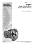
Series
Auxiliary
Transmission
MODELS:
APO1750-4
APO1000-4
Service Manual
TABLE OF CONTENTS
MODELS:
AMO/APO1000-4 & 1750-4
Page
GENERAL INFORMATION AND DESCRIPTION
Maintenance Lubrication & Power Flow
3-4
DISASSEMBLY
Removal Shifter Housing and Shaft Assemblies
Mainshaft - Manual
Countershaft
Drive Gear and Bearing Retainer
Shifter Housing Manual
Shifter Housing Air Shift
5
6-8
10
11
12
21-23
REASSEMBLY
Mainshaft - APO,AMO, ATO
Countershaft
Drive Gear and Bearing Retainer
Shifter Housing Manual
Mainshaft/Countershaft into case
Shifter Housing Air Shift
13
14
15-16
17
18-20
24-25
AIR SYSTEM CONTROLS
26
TOP MOUNTED PTO
Removal and Disassembly
Reassembly
35-37
42-46
TROUBLE SHOOTING
47
CAUTION
Do not tow vehicles equipped with Spicer transmissions without first pulling the axles or
disconnecting the drive shaft. Lubrication of the internal gear train is inadequate when the
vehicle is towed.
2
tech
Techline
line800-401-9866
800-401-9866
www.ttcautomotive.com
4 SPEED AUXILIARY TRANSMISSION
Manual & Air Shifted
MODELS:
AMO/APO1000-4 & 1750-4
GENERAL INFORMATION
MAINTENANCE INFORMATION:
We recommend that the procedures as outlined in the manual be followed when performing maintenance work on all transmissions.
REBUILD FACILITIES:
A suitable holding fixture or overhaul stand is desirable but not necessary to rebuild this unit. The flat bottom of the transmission case
provides a suitable working platform when the unit is placed on a sturdy shop table. For easier working conditions, table height should
be 28 - 30 inches. A light chain hoist should be used to handle the mainshaft and countershafts during removal and reassembly
procedures.
CLEANLINESS:
Transmissions should be steam cleaned prior to disassembly. Seal all openings before steam cleaning to prevent entry of dirt and
water which can damage serviceable parts. Dirt is abrasive and will cause premature wear of bearings and other parts. We suggest
that mechanics have a small wash tank to clean parts just prior to reassembly.
BEARINGS:
When a transmission is removed at relatively low mileage, bearings should be removed with pullers designed for this purpose. Wrap
the bearings to keep out dirt. Clean, inspect and lubricate all bearings just prior to reassembly. If accumulated mileage is over
150,000 miles, we suggest that all bearings be replaced.
END YOKES & FLANGES:
Hammering on end yokes and flanges, to remove or install them is not only destructive to the yoke or flange itself, but can also cause
serious internal damage. Hammering destroys or mutilates the pilot diameters and warps or bends the flange. Hammering on end
yokes will close- in the bearing bores or misalign yoke lugs and result in early failures of journal needle bearings, etc. Serious
damage can be done internally to bearings, thrust faces and washers, pilot bearings, etc., by hammering on external parts. In most
designs when the yoke/flange locknuts are tightened and secure, the internal bearings and gears are in proper location. When the
yoke/flange is driven on the shaft, two conditions can exist.
A. If the bearing fit is tight on the shaft, then usually the bearings will brinell as they must absorb the pounding forces.
B. If the bearing is loose, the shaft will keep moving inward until it is stopped by the internal parts such as pilot bearing thrust
washers, etc.
REPLACEMENT PARTS:
The exploded views of sub-assemblies which are incorporated here are for the mechanic's convenience and show the latest
material. The parts are arranged in their correct order and may also be used as a reference for assembly or disassembly of this unit.
POWER FLOW:
This Spicer auxiliary transmission is designed for heavy duty on and off-highway applications. The two countershaft design allows
the engine torque to be equally divided between the two countershafts. This provides a high ratio of torque capacity to transmission
weight. This also allows a reduction in the face width of each gear involved in the transmission. All the gears are in constant mesh
through spur teeth.
The AM01000-4 and 1241 transmissions have four forward speeds. All gear selections on the AM01000-4 and 1241 are made with a
mechanical shift lever only. All gear selections of the AP01000-4 and P1241 are made with an air control valve mounted on the shift
lever.
SPEEDOMETER DRIVE:
The rear mainshaffc bearing cap has provision for installation of speedometer driven gear and the attachment cable. Mainshaft
bearing cap can be rotated 180° for opposite speedometer installation.
3
tech line 800-401-9866
www.ttcautomotive.com
4 SPEED AUXILIARY TRANSMISSION
Manual & Air Shifted
MODELS:
AMO/APO1000-4 & 1750-4
MAGNETIC OIL CLEANER:
The rear drain plug has a magnetic stem attached to the plug to catch and hold metallic particles deposited in the oil.
P.T.O. SPECIFICATIONS:
Power Take-Off
Left Bottom: S.A.E. Standard Heavy Duty 8-Bolt
Right Bottom: S.A.E. Standard Regular Duty 6-Bolt
LUBRICATION
The 4-speed auxiliary, constant mesh transmission is designed to utilize splash lubrication for all bearings, shafts and gears. To
insure proper lubrication and operating temperatures in these units, it is most important that the proper lubricants be used and that
correct oil levels be maintained.
RECOMMENDED LUBRICANTS:
TEMPERATURE
ABOVE 0°F
BELOW 0°F
ABOVE 0°F
BELOW 0°F
GRADE
SAE30.40.or50
SAE 30
SAE 90
SAE 80
TYPE
HEAVY DUTY ENGINE OIL MEETING SPEC MIL-L-2104B OR MILL-45199 SERIES 3
STRAIGHT MINERAL GEAR OIL
The lubricant should not contain vegetable or animal oils, resin, soaps, graphite, fillers or foreign materials of any kind. The use of
extreme pressure additives, such as found in multi-purpose or rear axle type lubricants, is not recommended in a Spicer
transmission.
Capacity: Fill until oil runs out of fill hole on the transmission. 14 pints in level position. Higher when unit is installed on an angle.
NOTE: Regardless of the angle of installation, field experience indicates that this much oil is necessary for proper lubrication.
OIL CHANGES:
We recommend an initial oil change and flush at the first practical opportunity after the transmission is placed in service. This could
take place after a drive-away delivery, only 100 miles or 24 hours of off-highway service, but not more than 2,000 miles of over-thehighway. There are many factors that influence the oil change period and we have not specified a definite mileage interval. In general,
it is suggested that a drain and flush period be scheduled every 20,000 miles for normal over-the-highway operations. Off-thehighway usually requires oil change every 30 days. The oil level in the transmission should be checked every 2,000 miles onhighway, or every 24 hours in off-highway operation.
OVERFILLING:
Do not overfill this transmission with lubricating oil. Overfilling usually results in oil breakdown due to excessive heat and aeration
from the churning action of the gears. Early break-down of the oil will result in heavy varnish and sludge deposits that plug up oil ports
and build up on splines and bearings.
3
tech
Techline
line800-401-9866
800-401-9866
www.ttcautomotive.com
SHIFTER HOUSING REMOVAL
1. Shift the auxiliary into neutral. Remove the retaining
capscrews holding the shifter housing to the auxiliary case.
Separate the shifter housing and gasket from the case and lift
straight up.
MODELS:
AMO/APO1000-4 & 1750-4
2. Remove two nuts and washers from the two rear anchor
studs. Remove all retaining cap screw from adapter plate.
3. Remove the three Allen Head cap screws that are
countersunk. Separate adapter plate from case and lift
straight up.
5
tech
Techline
line800-401-9866
800-401-9866
www.ttcautomotive.com
MAINSHAFT & COUNTERSHAFT REMOVAL
MODELS:
AMO/APO1000-4 & 1750-4
1. Lock the auxiliary in two gears by moving the two shift
collars on the mainshaft forward into 2nd and 3rd gear. Use
two 9/16” sockets to remove the drive gear and mainshaft end
yoke locknuts and washers. Remove the drive gear and
mainshaft rear end yokes. Use a puller if the end yokes will
not come off readily.
2. Remove the capscrews from the drive gear bearing retainer.
Use soft hammer and tap on the retainer until it is separated
from the case.
3. Remove the capscrews from the front counter shaft
bearing caps. Remove the front bearing caps and gaskets.
Then use a pair of pry bars, between the case and the
retainer, and pry evenly until the bearing retainer and drive
gear assembly is removed from the case bore.
4. Drive gear bearing retainer and drive gear assembly
removed.
5. The 3rd-4th speed shift collar can be pulled from the
mainshaft through the front of the case.
6. Remove the capscrews from the countershaft rear bearing
caps and the mainshaft rear bearing cap. The mainshaft and
countershaft rear bearing caps and gaskets can now be
removed from the face of the case.
6
tech
Techline
line800-401-9866
800-401-9866
www.ttcautomotive.com
MAINSHAFT & COUNTERSHAFT REMOVAL
MODELS:
AMO/APO1000-4 & 1750-4
7. Remove bearing retaining snap rings from the front
countershaft.
8. Use brass punch to tap on the rear of each countershaft. Tap
on the countershafts until the front bearings have moved
forward about 1/4 inch, enough to get the puller on the outside
snap rings of the front bearings.
9. The front countershaft bearing bores have been machined
out to allow enough clearance for the jaws of a bearing puller.
Place the puller on the snap ring of the bearing and pull the
bearing off the shaft and out of the case bore.
10. Here the countershaft front bearings on the right and left
side have been removed. With the aid of a light chain hoist and
a hook to relieve some of the weight of the mainshaft, use a
soft mallet to drive the mainshaft assembly to the rear of the
case.
11. Install two countershaft supporting blocks - one on each
side.
12. Drive on countershafts to move the mainshaft far enough
to the rear to expose the rear bearings from the bores of the
case.
7
tech
Techline
line800-401-9866
800-401-9866
www.ttcautomotive.com
MAINSHAFT & COUNTERSHAFT REMOVAL
MODELS:
AMO/APO1000-4 & 1750-4
13. The rear countershaft bearings are two-piece bearings.
The outer race and roller assembly can be removed from the
inner race. Do not remove the inner race from the shaft
unless the bearing is going to be replaced.
14. A puller can now be used to remove the mainshaft rear
bearing from the mainshaft.
15. Remove the mainshaft spacer from the mainshaft.
16. Use a lift strap around the 1st-2nd shift collar and lift the
mainshaft sub-assembly up and out of the case. Lay the
mainshaft sub-assembly on a work bench for disassembly of
gears and related parts.
17. Use a lift strap around the countershaft behind the head
end gear and lift the countershaft assembly up and out of the
case. Do the same for the other countershaft.
8
tech
Techline
line800-401-9866
800-401-9866
www.ttcautomotive.com
MAINSHAFT DISASSEMBLY
MODELS:
AMO/APO1000-4 & 1750-4
1. Remove 1st speed gear with snap ring and external spline
thrust washer from the rear of the mainshaft.
2. Remove 1st speed gear internal spline thrust washer from
the rear of the mainshaft.
3. Remove snap ring and clutch collar from rear of the
mainshaft.
4. At the front of the mainshaft, remove the snap ring from the
mainshaft groove located under the bore of the overdrive
gear.
5. Remove the internal and external spline thrust washers of
the overdrive gear. Remove the overdrive gear with the snap ring
6. Remove 2nd speed gear with snap ring. The external and
internal spline thrust washers of the 2nd speed gear can be
removed from the shaft.
from the mainshaft.
7. The 2nd speed gear snap ring to the shaft is removed. The
1st-2nd speed gear shift collar and 1st speed gear snap ring
to the shaft can be taken off the mainshaft.
9
tech
Techline
line800-401-9866
800-401-9866
www.ttcautomotive.com
COUNTERSHAFT DISASSEMBLY
1. If the countershaft rear bearings are to be replaced, use a
puller to remove the inner race off the countershaft.
MODELS:
AMO/APO1000-4 & 1750-4
2. Remove spacer snap ring from rear of countershaft.
Note:
If gears on countershafts require replacement because
of tooth damage, or ratio change, etc., press all gears
but integral Lo-Lo gear off the shaft.
3. Support head end (direct drive) gear with parallel bars as
close to the hub as possible. Using an arbor press, press
countershaft out of head end gear.
4. Support 4th speed gear with parallel bars as close to the
hub as possible. Using an arbor press, press countershaft
out of 4th speed gear.
5. Using an Arbor Press, press the 2nd speed gear off the
countershaft
6. The Lo-Lo gear (1st speed gear) is an integral part of the
countershaft and does not press off. Keys are still intact in the
keyway of the counter-shaft and can be removed, if
necessary.
Note:
Countershaft has a long continuous keyway. As each
gear is pressed from the shaft, the key may come away
with the gear instead of staying in the keyway.
Note:
The later model countershafts no longer use three
separate keys. One long key is now assembled to the
countershaft keyway.
10
tech
Techline
line800-401-9866
800-401-9866
www.ttcautomotive.com
DRIVE GEAR & BEARING RETAINER DISASSEMBLY
MODELS:
AMO/APO1000-4 & 1750-4
1. The drive gear front bearing cap and drive gear assembly
as it was removed from the front of the case.
2. The capscrews holding the front bearing cap and gasket to
the drive gear bearing retainer have been removed. The
bearing cap has been removed from the retainer. Remove
front bearing cap oil seal if it is damaged and requires
replacement.
3. Support bearing retainer assembly on its flange and press
drive gear free of bearing retainer, bearings and spacer.
4. Use snap ring pliers to remove drive gear retaining snap
ring.
5. Remove the drive gear pocket bearing by prying out with a
large screwdriver or equivalent. Use caution not to mar, or
gouge pocket machined diameter with screwdriver or similar
tool.
6. Use a brass drift to remove bearing from the front of the drive
gear bearing retainer. The drive gear spacer can be removed
from inside the retainer, at this time.
7. Use a brass drift to remove the outer bearing assembly
of the drive gear rear bearing from the retainer.
11
tech
Techline
line800-401-9866
800-401-9866
www.ttcautomotive.com
SHIFTER HOUSING DISASSEMBLY - MANUAL SHIFT
MODELS:
AMO/APO1000-4 & 1750-4
1. Remove the retainer plugs, poppet springs and poppets at
the front of the shifter housing located on either side of the
shift rails.
2. With the cover lying on its top on a work bench remove the
set screw holding the 1st-2nd shift fork to the shift rail.
3. Slide the 1st-2nd shift rail out through the front of the cover.
The two stop sleeves and shift fork can then be lifted out of the
cover.
4. Remove the set screw holding the 3rd-4th shift fork to the
shift rail.
5. Pull the shift rail out through the front of the cover, removing
the long stop sleeve as the shift rail is pulled from the cover.
Remove the 3rd-4th shift fork and short stop sleeve.
6. Remove the interlock from the interlock hole between the
two shift rails. If the shift rod seals at the front of the cover are
to be replaced, then remove the seals from the housing bores
at this time.
12
tech
Techline
line800-401-9866
800-401-9866
www.ttcautomotive.com
MODELS:
AMO/APO1000-4 & 1750-4
MAINSHAFT ASSEMBLY - AMO APO ATO
Note:
When assembling the mainshaft, the internal and external spline
thrust washers are all of the same thickness and size and are
interchangeable from one gear to another. Before assembly of all
gears on the mainshaft, inspect all thrust washers and snap rings. If
washers show face galling or tooth wear indentations, the washers
should be replaced. If the snap rings have been extended or
distorted, they should be replaced. Lubricate old or new thrust
washers with S.A.E. #50 engine oil on the thrust faces as they are
assembled. Both shift collars are identical. Either end of collars can
be installed on the shaft at time of assembly.
1.
Air Shift
Manual Shift
2. Install the 1st & 2nd speed clutch collar & retaining snap
rings in the grooves on the mainshaft on either side of the 1st2nd speed gear shift collar.
3. Place an internal spline thrust washer on the mainshaft.
Place an external spline thrust washer next to the internal
spline washer.
4. With the 2nd speed gear snap ring in the gear, place the
2nd speed gear on the mainshaft. The long spline in the gear
bore toward the shift collar.
5. Place the 4th speed gear (overdrive) on the mainshaft. The
snap ring is in the bore of the gear and the long spline of the
gear bore faces the front of the shaft. Place an external spline
thrust washer on the shaft and into the bore of the gear.
6. Place an internal spline thrust washer on the shaft and into
the bore of the gear. Install the snap ring in the last groove on
the mainshaft in the bore of the overdrive gear. Make certain
all snap rings are seated firmly in place.
7. On the rear of the mainshaft place an internal spline and
external spline thrust washer up against the 1st gear mainshaft
snap ring.
Note: To check for proper assembly of the mainshaft gears onto
the mainshaft, the mating shift collar must make full entry into each
gear bore.
8. The 1st speed gear with the snap ring in the gear bore is
placed on the shaft. The long spline in the gear bore going
toward the 1st-2nd speed shift collar. Lay the mainshaft on the
bench for later installation into the case.
13
tech
Techline
line800-401-9866
800-401-9866
www.ttcautomotive.com
COUNTERSHAFT ASSEMBLY
Note:
It is advisable to Coat bores of all the gears with oil when
pressing the gear on the countershaft. We recommend
that the keys for each gear be installed in the shaft
keyway one at a time, as the countershaft is pressed into
the gear bore. Note that all three keys are the same size,
so that they can be used interchangeably in any gear. If
keys become mutilated or burred after assembly to the
shaft keyway, use mill file to align sides, remove burrs,
etc. This prevents chips and slivers from peeling off and
lodging between gear hub faces.
1. Secure the key into keyway of countershaft by driving on
the key with a hammer. Support 2nd speed gear (underdrive)
with long hub up. Align key with gear keyway and press shaft
and key into gear. Seat the gear face of shaft firmly against
the face of 2nd speed gear (underdrive). Key must be under
the face of gear.
MODELS:
AMO/APO1000-4 & 1750-4
Note:
As the countershaft is pressed into each gear, make
certain any metal chips or slivers are removed from the
gear hub faces
2. Secure the key for the 4th speed gear (over-drive) into the
countershaft keyway. Support the overdrive gear with the long
hub down. Press the shaft and key into the gear. Seat the gear
face firmly against the face of the underdrive speed gear. The
key must be under the face of the gear.
IMPORTANT
The key face must not protrude beyond the face of the
3rd speed gear (direct drive) because the countershaft
front bearing inner race face rests against the face of the
gear hub.
Notice there is a tooth timing mark "V" on the tooth web
of the 3rd speed gear (direct drive). Be sure that it aligns
itself to the center of the gear keyway. Use white paint on
the timing marks"V" for easy identification on later
assembly.
3. Secure the third key in the keyway of the countershaft.
Support the 3rd speed gear (direct drive) with the long hub
up. Press the shaft into the gear, seating the gear face firmly
against the face of the 4th speed gear (overdrive). The key
must be under the face of the gear.
tech
Techline
line800-401-9866
800-401-9866
Note:
The later model countershafts no longer use three
separate keys. One long key is now assembled to the
countershaft keyway.
14
www.ttcautomotive.com
DRIVE GEAR & BEARING RETAINER ASSEMBLY
MODELS:
AMO/APO1000-4 & 1750-4
1. Install pocket bearing.
2. Install 3rd speed gear into the drive gear and install retaining
snap ring.
3. Install bearings and spacers into drive gear bearing
retainer.
4. Place the spacer on the drive gear stem. It will rest against
the drive gear rear bearing.
5. Bearings and spacers installed.
6. Install bearing retainer onto drive gear assembly.
15
Techline
line800-401-9866
800-401-9866
tech
www.ttcautomotive.com
DRIVE GEAR & BEARING RETAINER ASSEMBLY
7. Install bearing retainer front cap and seal assembly. Make
sure to align oil hole on cap and retainer.
MODELS:
AMO/APO1000-4 & 1750-4
8. Install six (6) bearing cap retaining screws.
9. If previously removed, install breather into drive gear
assembly.
16
tech
Techline
line800-401-9866
800-401-9866
www.ttcautomotive.com
SHIFTER HOUSING ASSEMBLY
MODELS:
AMO/APO1000-4 & 1750-4
1. Install poppet spring and poppet. Assemble 3rd-4th speed
shift rail is assembled to the shifter housing through the front
seal and bore. The small stop sleeve and 3rd-4th speed shift
forks are placed on the rail. The long hub of the fork going to
the rear.
2. Slide the long stop sleeve on the shift rail behind the fork.
3. Align the set screw hole of the shift rail with the set screw
hole of the fork. Secure the fork to the rail with the set screw.
Torque the set screw to 40-50 lb. ft.
4. Drop the interlock into the interlock and poppet cross hole
of the front boss. Make sure interlock seats in neutral notch of
the shift rail. Secure with the poppet hole plug.
5. Assemble the 1st-2nd speed shift rail and fork to the
housing. The long hub of the fork goes to the front. The long
stop sleeve to the front and the short stop sleeve to the rear of
the fork.
6. Align the set screw hole of the rail with the set screw hole of
the fork. Secure the fork to the shift rail with the set screw.
Torque the set screw to 40-50 IDS. Ft.
7. Assemble the poppet ball and poppet spring into the
access hole of the housing. Secure with the poppet hole plug.
Check the shifting of both rails in and out of their neutral
position to make sure they travel freely and completely into all
shift positions.
17
tech
Techline
line800-401-9866
800-401-9866
www.ttcautomotive.com
MODELS:
AMO/APO1000-4 & 1750-4
MAINSHAFT COUNTERSHAFT DRIVE GEAR ASSEMBLY INTO CASE
1. Use notch as reference point for timing marks on head end
gear.
2. Install countershaft subassemblies. Try to keep the timing
marks (notch) toward the center of the case. This timing mark
must be mated to the drive gear timing mark later in assembly.
Do not install countershaft front or rear bearings at this time.
3. With a sling placed around the 1st-2nd speed shift collar
and the use of a light chain hoist, lower the mainshaft
assembly into position in approximate center of the case
rear bore.
4. Leave the hoist and sling in place for support on the
mainshaft in its position until the drive gear assembly and
mainshaft rear bearing have been assembled into the case.
Place the 3rd-4th speed shift collar on the mainshaft.
5. Place the mainshaft gear spacer on the shaft with the
large flat side going against the hub of the 1st-2nd speed
gear.
6. Install the front drive gear and bearing cap assembly with
gasket into the front case bore and onto the pilot stem of the
mainshaft. Torque the capscrews to 60-80 Ibs. Ft.
18
tech
Techline
line800-401-9866
800-401-9866
www.ttcautomotive.com
MODELS:
AMO/APO1000-4 & 1750-4
MAINSHAFT COUNTERSHAFT DRIVE GEAR ASSEMBLY INTO CASE
7. Use a piece of tubing or suitable driver to drive on the inner
race of the mainshaft rear bearing. Seat the outer snap ring
on the bearing against the main case counterbore.
8. If the speedometer driven gear was removed from the
bearing cap, assemble it at this time. Inspect and replace the
mainshaft rear bearing cap oil seal if necessary. Align the oil
port holes to the return holes on the bearing cap. Install the
rear bearing cap with gasket on the mainshaft rear bearing
and case face. Torque the capscrews to 60-80 lbs. ft.
9. Important: With all timing gears painted, bring timing teeth
of countershaft head end gears parallel to bottom of case, or
pointing to the center of the case. Position drive gear timing
teeth (two) where they will match and mate to the timing teeth
of the countershaft gears.
10. Install the countershaft front bearing onto the countershaft.
Install the other front counter-shaft bearing in the same
manner. Make certain timing marks of countershaft head end
gear and drive are still in mesh.
11. Install the countershaft front bearing retaining snap rings.
12. Install the countershaft front bearing caps with gaskets to
the case face. Secure the caps with the capscrews and torque
to 25-32 Ibs. Ft.
19
tech
Techline
line800-401-9866
800-401-9866
www.ttcautomotive.com
MODELS:
AMO/APO1000-4 & 1750-4
MAINSHAFT COUNTERSHAFT DRIVE GEAR ASSEMBLY INTO CASE
13. Install outer race and roller assembly of the countershaft
rear bearing onto each shaft. Tap the bearing outer race with
roller assembly onto the inner race and into the case bore of
each countershaft. Install the countershaft rear bearing caps
and gaskets onto the case. Secure with capscrews and
torque to 25-32 Ibs. ft.
14. Shift the 1st-2nd and 3rd-4th speed shift collars into gear,
locking it into two gears. Install the end yokes onto the drive
gear stem and mainshaft splines. Install the washers on the
shafts with the locknuts. Use a 2 9/16" socket wrench to torque
the drive gear shaft and mainshaft locknuts to 550-600 Ibs. ft.
Move the 1st-2nd shift collar to the neutral position. Turn the
drive gear end yoke to roll the gear train. If the teeth timing
marks are in their correct position the entire gear train will roll
freely. If the timing teeth have not been set correctly, or have
escaped from their proper position, the gear train will lock-up
after several turns of the drive gear. If this happened, the shafts
must be retimed. If the timing is correct, move the 3rd-4th shift
collar to the neutral position and proceed with the final
installation of the shifter housing.
15. Install adapter plate and gasket.
16. Install the three Allen head cap screws.
IMPORTANT
We recommend using a torque wrench for verification
of the specified 550-600 Ibs. ft. torque on the input and
output shaft lock-nuts.
17. Install cap screw. Torque cap screws to 25-32 lb. ft.
20
tech
Techline
line800-401-9866
800-401-9866
www.ttcautomotive.com
SHIFTER HOUSING DISASSEMBLY
Air Shifted
MODELS:
APO1000-4 & 1750-4
1. Remove the two air connectors and two elbows at the front
of the shifter housing.
2. Remove the two retaining plugs and stop pins from the top
of the shifter housing.
3. Remove the snap ring from in front of the piston cylinder
cap.
4. Remove the piston cylinder cap with "0" ring and washer.
Follow the same procedure for the adjacent shift rail.
21
tech
Techline
line800-401-9866
800-401-9866
www.ttcautomotive.com
SHIFTER HOUSING DISASSEMBLY
Air Shifted
MODELS:
APO1000-4 & 1750-4
5. Remove the snap ring from inside each of the piston
housing bores.
6. Also remove the locknut from the 3rd-4th piston rod.
7. Now remove the set screw holding the 3rd-4th speed shift
fork to the piston rod.
8. Use a brass drift to drive the 3rd-4th speed piston rod
forward. As the rod comes forward, the internal piston can be
removed from the front of the housing. The piston rod with the
brass piston rod bushing can also be pulled from the front of
the housing.
9. Remove the locknut from the 1st-2nd speed piston rod
10. Use a soft mallet to drive the 1st-2nd speed piston rod
forward.
22
tech
Techline
line800-401-9866
800-401-9866
www.ttcautomotive.com
SHIFTER HOUSING DISASSEMBLY
Air Shifted
MODELS:
APO1000-4 & 1750-4
11. Remove the set screw holding the shift fork to the piston
rod. Take the shift fork from the piston rod. The internal piston
with the front external piston can be removed from the end of
the rod. Remove the 1st-2nd speed piston rod with the piston
rod brass bushing from the housing.
12. The piston rod with brass piston rod bushing and the
internal piston.
13. Remove the cylinder snap ring from the bore of the piston
housing.
14. Remove the rear external piston from the piston housing
bore. Repeat the same procedures ar the adjacent piston
side.
15. Remove the two external piston "0" rings in each of the
piston housing bores.
23
tech
Techline
line800-401-9866
800-401-9866
www.ttcautomotive.com
SHIFTER HOUSING ASSEMBLY
Air Shifted
MODELS:
APO1000-4 & 1750-4
1. Inspect and replace all damaged or worn "0" rings before
reassembly of the cover
2. Place the 1st-2nd speed piston rod into the shifter housing.
Place the 1st-2nd speed shift fork on the piston rod with the
long hub toward the front. Place the brass internal piston rod
bushing on the end of the rod. Check and make sure the
interlock is still in the cross hole between the rods.
3. Secure the shift fork to the piston rod with the set screw.
Torque the set screw to 40-50 Ibs.ft. Use a suitable driver to
drive the piston rod bushing into the piston housing bore.
Flange on bushing will seat against the face inside the piston
housing bore.
4. Repeat the same procedures for the adjacent piston rod
fork. Place the rear outer piston "O” ring into each piston
housing bore.
5. Place the rear outer piston into each piston housing bore.
6. Assemble a snap ring into each piston housing bore.
24
tech
Techline
line800-401-9866
800-401-9866
www.ttcautomotive.com
SHIFTER HOUSING ASSEMBLY
Air Shifted
MODELS:
APO1000-4 & 1750-4
7. Assemble the front outer piston "0" ring into each piston
housing bore.
8. Place the internal piston with the front outer piston
assembled to it, into the bore and onto the piston rod. Repeat
the same procedure for the adjacent piston rod. Secure the
internal pistons on the piston rods with the locknuts.
9. Assemble the snap ring to each piston housing bore.
10. Assemble the cylinder caps with "0" ring and washer in
each piston housing bore.
11. Place the snap ring at the front of each cylinder cap.
12. Place the stop pins and plugs in the top of the shifter
housing. If remove reinstall air fitting to the front of the shifter.
25
tech
Techline
line800-401-9866
800-401-9866
www.ttcautomotive.com
CONTROL VALVE & MOUNTING PARTS
Air-Matic
MODELS:
AMO/APO1000-4 & 1750-4
Tubing Diagram
26
tech
Techline
line800-401-9866
800-401-9866
www.ttcautomotive.com
MODELS:
1000-4 & 1750-4
AIR SHIFT CONTROLS
Air Shifted
Removal of Air Control Lines:
1. Disconnect air line fitting from two air cyinders input ports.
Note:
Disassembly and Reassembly
of Shift Selector Control Valve:
1. Remove three cap screws and lockwashers and remove
valve top.
Note:
Identify air lines as removed with tag or tape for
convenience at time of reconnecting lines to cylinders.
1 == Lo-Gear \ On right side of case from
2 = Underdrive J driver's seat.
3 = Direct \ On left side from driver's
4 = Overdrive \ seat.
2. Tie air lines, two each, to the right and left side of the
chassis frame.
Note:
This will eliminate damage to the plastic outer and most
important, inner air lines from pinching or sharp
bending. This will restrict or stop air passing through the
lines when reconnected to the air cylinders.
3. Disconnect dry tank air line from the transmission air filter
regulator.
REMOVAL OF AIR LINES:
Note:
If repair and replacement of "O" Rings in shift cylinders
is required refer to Spicer parts list catalog for "O" ring
kit required.
Disassembly Of Air Control Valve
Assembly On Shift Lever:
1. Disconnect all fittings from beneath the
control valve. Using tape that can be written on,
identify each line with the air port involved, per
the following:
(E) . . . Air Dump, or discharge line
1). . . Lo Gear Air Charge Line
2). . . Underdrive line
3). . . Direct line
4). . . Overdrive line
5). . . Neutral Charge line
2. Remove shift knob from top of control valve.
Remove control valve from shift lever.
Top of valve is preloaded by a rotor pressure spring.
2. Displace pressure spring.
Note:
Mark with red pencil, or ink the tab location of the top
rotor cam with relation to the main value body. Note that
these rotor tabs are held in solid location to slots in the
value top. Tab location to main valve body is important
when reassembling the whole valve unit and its correct
function.
3. Remove top rotor and plastic rotor in valve
body by pulling upward on selector finger.
Note:
As rotor moves out of valve body, a small plunger will
pop out from side of the rotor. Remove plunger and
preload spring from rotor body. Remove the rotor
completely from the valve body.
4. Inspect all "O” rings on rotor body and small
plunger for wear, cuts, etc.
Note:
If "O" ring repair and replacement is required refer to
Spicer parts list catalog for "O" ring kit required for
selected control valve.
Reassembly of Control Valve:
Note:
It is recommended that "O" ring lubrication be used
on "O" rings before reassembly of rotor into the valve
body.
1. After replacing all "O" rings on rotor and side plunger,
assemble side plunger spring and plunger into the rotor.
2. Insert rotor into valve body diameter. Preload side plunger in
correct location to body diameter.
Use CAUTION: DO NOT PINCH "O” RINGS.
3. With rotor fully installed in valve, place selector finger of
rotor in "E" position at bottom of valve.
27
tech
Techline
line800-401-9866
800-401-9866
www.ttcautomotive.com
MODELS:
APO1000-4 & 1750-4
AIR SHIFT CONTROLS
Air Shifted
4. Place top rotor in correct position. Locate tabs in line with
red ink or pencil marks put on valve at disassembly.
5. Place pressure spring on top of rotor. Place valve top on
pressure spring with "N" or Neutral located in alignment with
selector finger.
6. Preload top of valve. Reassemble lock-washer and
capscrews to top. Tighten capscrews firmly.
7. Check valve operation by placing selector in each position
on valve top from neutral through number 4 position and back
to neutral (N). Make sure that finger locks into each position
noted.
Note:
If selector finger moves into any position with very little
force, it indicates top plastic rotor is not locating
correctly, because it has excessive wear on the cam
teeth of the top rotor to the main rotating rotor or the
pressure spring is weak or broken.
Assembly of Shift Lever
Control Valve:
1. Assemble jam nut to shift lever. (Turn down to last thread.)
Assemble control valve shift lever threads and lock in position
with jam nut. Assemble shift lever knob to top of control valve.
2. With air lines identified with tape at disassembly, connect
proper air line identified to proper valve port E, 1, 2, 3, 4, S.
CAUTION: Do not over tighten fitting as it could collapse the
plastic inner air line and pinch off air supply.
3. Place control valve selector finger in neutral (N) position.
4. Assemble pressure regulator to bracket with clamp.
5. Locate regulator on right or left side of main transmission
shift cover. Secure bracket to shifter cover with lockwashers
and capscrews. This may vary depending on the O.E.M.
vehicle installation.
Check Air Operation of Rear
Unit After Complete Reassembly
of Air Controls into unit and Cab:
Main unit shift lever and the auxiliary unit air control valve are
now in neutral position (N). Start engine and build up cab
pressure of 100-120 P.S.I.
Note:
If air pressure gauge was installed at air regulator,
check regulated air pressure coming through rear unit
control system. Air pressure for control of rear unit
shifting must be 50-55 P.S.I.
1. With proper air pressure build up for shifting auxiliary, shut
off the engine. Check for any possible air leaks in the cab
control valve, also filter regulator, at shift cylinders air line
fittings.
2. If no air leaks are found in the air system, select position 1
(Lo) on cab shift lever control.
Note:
Check shifting before connecting the auxiliary to axle
driveline. Thereby, transmission end yoke can be
turned by hand to allow engagement of transmission
shift collar teeth to mating gear teeth for gear position
desired to check out air shift system.
3. Select position number 2 on shift lever control. Check air
cylinder shift finger to be sure it has made a full engagement in
the transmission or that no hang up has occurred.
4. In turn, select positions number 3 and number 4.
5. Reverse position selection from number 4 to neutral (N).
Check selection of gears again by this reverse movement of
control valve selector finger to each position.
6. As each gear selection is made on the shift lever valve, (E)
empty line will exhaust air from that particular line. This is done
to dump the air from one side of the air cylinder while the other
side of the cylinder is being charged with air for gear position
required.
6. Connect DRY TANK air supply line to filter regulator port.
7. Connect plastic line Number 5 from cab valve control to air
regulator unit "OUT" port.
7. After the garage test is proven satisfactory for all shifts, the
tractor should be road tested several miles to be sure that all
shifts are operating correctly.
All air lines have now been properly hooked up throughout air
controls of units.
28
tech
Techline
line800-401-9866
800-401-9866
www.ttcautomotive.com
DISASSEMBLY AND REASSEMBLY OF FILTER-REGULATOR
MODELS:
AMO/APO1000-4 & 1750-4
Note:
The APO1000-4& 1750-4 models use filter-regulator
pre-set at 50-55 P.S.I. Use only petroleum base solvent
to clean parts. Blow air through filter (inside to outside)
to dislodge surface contaminants. Do not disassemble
regulator section (9), as it is not field repairable.
MAINTENANCE:
1. Clean or replace filter element (7) every six months to one
year or whenever slow shifting is encountered. Element
should be replaced after three cleanings. If regulator
malfunction is indicated, replace entire unit.
2. To service filter section, shut off air pressure. Unscrew bowl
(1) and remove 0-Ring (2). Unscrew stud (4). Remove louver
(5), upper gasket (6), element (7), and lower gasket (8) from
stud. Do not disassemble regulator section (9).
3. After cleaning, inspect parts carefully; replace any
damaged parts.
4. Reassemble by installing element (7) on stud (4) so that
large end of internal taper (thinnest wall section) is toward hex
on stud. Torque stud to 5-10 inch pounds.
5. Apply a wipe coat of Dow Corning DC7 Silicone Grease (or
equivalent) to 0-Ring (2) seating surfaces on regulator (9) and
bowl (1). Apply a light, even coat of Molykote "G" (or
equivalent) to bowl threads. Torque bowl to 5-10 inch pounds.
If drain valve (3) was removed, reinstall and torque to 10-15
inch pounds.
29
tech
Techline
line800-401-9866
800-401-9866
www.ttcautomotive.com
GEARS & RELATED PARTS
MODELS:
APO1000-4 & 1750-4
30
tech
Techline
line800-401-9866
800-401-9866
www.ttcautomotive.com
GEARS & RELATED PARTS
Manual Shifted
MODELS:
AMO1000-4 & 1750-4
31
tech
Techline
line800-401-9866
800-401-9866
www.ttcautomotive.com
MODELS:
APO1000-4 & 1750-4
AIR-MATIC CONTROLS
Shifter Housing Parts
32
tech
Techline
line800-401-9866
800-401-9866
www.ttcautomotive.com
SHIFT HOUSING PARTS
Manual Shifted
MODELS:
AMO1000-4 & 1750-4
33
tech
Techline
line800-401-9866
800-401-9866
www.ttcautomotive.com
MODELS:
AMO/APO1000-4 & 1750-4
CASE & BEARING CAPS
with Related Parts
34
tech
Techline
line800-401-9866
800-401-9866
www.ttcautomotive.com
TOP MOUNTED PTO SECTION
MODELS:
AMO1000-4 & 1750-4
REMOVAL of TRANSMISSION SHIFT FORKS & INTERMEDIATE GEAR RELATED PARTS
The Top Mounted PTO comes with the output shaft facing to the front or to the rear. When reassembling the Top Mounting PTO, the
desired direction of the output shaft can be attained by simply having the threaded end of the output shaft and the output shaft bearing
cap (open end) assembled to the front or to the rear of the PTO.
1. For disassembly, place the PTO on the bench with the
forks upright. If the output yoke or flange has not been
removed from the output shaft do so now.
2. Remove the poppet plugs, springs and balls from the
transmission shift rod poppet holes.
3. The retainer, poppet spring and ball is removed from the
output shift rod poppet hole.
4. Remove the set screw holding the shift fork to the shift rod.
Pull the shift rod from the fork and out through the front of the
case.
5. Pull shift rod from fork and through the front of the case.
6. Remove the nut and washer from the rear of the
intermediate shaft.
35
tech line
Tech
line 800-401-9866
800-401-9866
www.ttcautomotive.com
TOP MOUNTED PTO SECTION
MODELS:
AMO1000-4 & 1750-4
REMOVAL of TRANSMISSION SHIFT FORKS & INTERMEDIATE GEAR RELATED PARTS
7. Use a brass punch to drive the intermediate shaft forward.
Be careful no to damage the threads on the end of the shaft.
8. While driving shaft out - catch ball coming out of the front of
shaft - also catch the shaft.
9. If the intermediate shaft does not readily move free of the
case bore, a ram type puller can be used to pull the shoulder
of the shaft from the bore of the case.
10. The shaft is removed from the intermediate gear and case.
11. Lift the intermediate gear and front washer out of the
case.
12. If the bearing cones or bearing cups are damaged and
need to be replaced, use a brass drift to drive the bearing cups
from the inside out of the gear bore.
36
tech
Techline
line800-401-9866
800-401-9866
www.ttcautomotive.com
TOP MOUNTED PTO SECTION
MODELS:
AMO1000-4 & 1750-4
REMOVAL of TRANSMISSION SHIFT FORKS & INTERMEDIATE GEAR RELATED PARTS
13. Use a magnet or turn the case on its side to remove the
interlock pin from the interlock hole.
14. After removing the set screw from the transmission shift
fork, slide the shift rod from the fork and out through the front of
the case.
37
tech
Techline
line800-401-9866
800-401-9866
www.ttcautomotive.com
REMOVAL OF THE REVERSE SHAFT & RELATED PARTS
MODELS:
AMO1000-4 & 1750-4
1. The four capscrews holding the reverse shaft, rear bearing
capCpan be removed.
2. The reverse shaft rear bearing cap and gasket is now off the
case. The four capscrews holding the reverse shaft front
bearing cap can be removed.
3. Remove the reverse drive gear snap ring from the
snapping groove to the center of the shaft.
4. Move the reverse shaft forward until the outer race with
cylindrical roller bearings comes out of the case bore.
Note:
The reverse gear and reverse drive gear hub faces seat
against the snap rings held in place by the bearing inner
races. For easier removal of the snap rings, tap each
gear to the outside until the snap ring turns freely in the
groove.
5. Lift the reverse shaft assembly up and out of the case.
38
tech
Techline
line800-401-9866
800-401-9866
www.ttcautomotive.com
MODELS:
AMO1000-4 & 1750-4
REMOVAL OFDisassembly
THE REVERSEand
SHAFT
& RELATEDofPARTS
Reassembly
Filter-Regulator
6. With the aid of a small arbor press and by supporting the
gear with parallel bars, the bearing inner race can be
removed from each end of the shaft. If the snap rings have
been distorted, remove them from the shaft and replace with
new snap rings.
7. Use a soft hammer to tap the reverse shaft rear bearing
outer race and rollers from the case bore.
8. Remove the four capscrews from output shaft bearing
cap.
9. The output bearing cap and gasket is then removed from the
case. Inspect and replace the output bearing cap oil seal if
worn or damaged.
39
tech
Techline
line800-401-9866
800-401-9866
www.ttcautomotive.com
REMOVAL OF THE OUTPUT SHAFT & RELATED PARTS
MODELS:
AMO1000-4 & 1750-4
1. Remove the four capscrews from the output shaft rear
bearing cap.
2. The bearing cap and gasket is removed from the case.
Remove the lockwire and two capscrews holding the rear
bearing retaining washer to the shaft.
3. Here a piece of flat stock 3" x 6" and ½” wide is placed
between the hub of the output sliding gears and the shoulder
of the output drive gear sleeve. As the output shaft is moved to
the rear, the bearing outer race with rollers will come out of the
rear case bore.
4. Use a soft mallet to drive the output shaft rearward and
through the output gear sleeve. When the shaft is moved far
enough to the rear so as to expose the lock ring, which is in
the groove of the shaft and seats against the inside shoulder
of the sleeve, remove the lock ring from the groove toward
the front of the shaft.
5. The two-piece bearing and bearing washer on the front of
the output shaft are removed as the shaft is driven rearward.
6. Once the output shaft has been driven free of the output
gear sleeve, the output gear, lock ring and sleeve can be lifted
out of the case. The output shaft can be slid out through the
rear of the case.
40
tech
Techline
line800-401-9866
800-401-9866
www.ttcautomotive.com
REMOVAL OF THE OUTPUT SHAFT & RELATED PARTS
MODELS:
AMO1000-4 & 1750-4
7. The output shaft rear bearing inner race can be removed
from the shaft with the aid of a small hand press.
8. Remove bearing inner race and bearing washer from the
shaft.
9. The output sliding gear can be lifted from the bottom of the
case.
10. Remove the two capscrews holding the output sliding
gear shift fork to the shift rod.
11. Slide the rod out through the case front and remove the shift
fork from the case as the rod passes out of the fork. Inspect the
four shift rod oil seals and if they are damaged or worn, remove
them from the case and replace them with new seals.
41
tech
Techline
line800-401-9866
800-401-9866
www.ttcautomotive.com
ASSEMBLY OF OUTPUT SHAFT & RELATED PARTS
MODELS:
AMO1000-4 & 1750-4
1. Assemble the output slide gear shift fork to the shift rod with
the two capscrews. The spot face on the shift fork facing out.
Torque the two capscrews to 40-50 Ibs. ft.
2 Place the output slide gear in the case with the fork slot
toward the front.
3. Slide the output shaft through the rear case bore. Align the
spline of the output shaft with the splined bore of the slide
gear and move the shaft on through the gear until the snap
ring rests against the hub of the output slide gear. Check to
make sure the sleeve pin is aligned to one of the grooves in
the output shaft spline.
4. The output gear snap ring and the output gear sleeve are to
be started on the threaded end of the output shaft. Do not
secure them all the way on the shaft at this time.
5. Place the output drive gear over the output sleeve on the
shaft. The clutch teeth on the gear hub face toward the output
slide gear.
6. Move the output shaft and gear assembly to the front of the
case. Use a soft mallet to drive on the rear of the output shaft.
Drive the shaft forward until the snap ring is seated in the
snapping groove of the shaft and against the shoulder in the
bore of the output gear sleeve.
42
tech
Techline
line800-401-9866
800-401-9866
www.ttcautomotive.com
ASSEMBLY OF OUTPUT SHAFT & RELATED PARTS
MODELS:
AMO1000-4 & 1750-4
7. Place the output shaft bearing washer, with the flat side to
the gear, on the rear of the output shaft. The bearing inner
race goes on the shaft with the flanged end to the inside. Use
a suitable driver to secure the bearing inner race to the shaft.
The bearing washer will seat firmly against the shoulder of
the shaft once the bearing inner race has been driven into
position.
8. Secure the bearing to the shaft with the bearing retaining
washer and two capscrews. Torque the capscrews to 25-32
Ibs. Ft. Lockwire the two capscrews.
9. Align the oil return hole of the bearing cap and gasket to the
oil port hole in the case. Secure the output shaft rear bearing
cap and gasket to the case with the capscrews. Torque the
capscrews to 25-32 Ibs. ft.
10. The bearing inner race goes on the shaft with the flanged
end to the inside.
11. Inspect and replace, if necessary, the output shaft
bearing cap oil seal. Align the oil return holes of the bearing
cap and gasket to the oil port in the case. Secure the output
shaft bearing cap and gasket to the case with the capscrews.
Torque the capscrews to 25-32 Ibs ft.
43
tech
Techline
line800-401-9866
800-401-9866
www.ttcautomotive.com
ASSEMBLY OF THE REVERSE SHAFT & RELATED PARTS
1. Assemble the reverse gear to the reverse shaft with the
ground face of the gear hub facing out. Place the snap ring
into position in the snap ring groove behind the reverse gear.
Drive the inner race on the on the reverse shaft with the
flanged end seating firmly against the reverse gear hub. Do
not secure the reverse drive gear and snap ring into position
on the shaft, at this time.
MODELS:
AMO1000-4 & 1750-4
2. Lower the reverse shaft assembly into the case. The reverse
gear goes to the rear of the case.
3. Place the reverse drive gear snap ring into the snap ring
groove in the shaft.
4. Use a suitable driver to secure the bearing inner race on the
shaft. The flanged end seats firmly against the hub of the
reverse drive gear. Align the shaft in the center of the case
bore and place the outer race with cylindrical rollers on the
inner race. Tap evenly on the outer bearing in the case bore.
Repeat procedure for the inner race and outer cylindrical
rollers at the rear of the reverse shaft.
5. Align the oil return holes of the bearing cap and gasket to
the oil port hole in the case.
6. Secure the front bearing cap and gasket to the case with the
capscrews. Torque the capscrews to 25-32 Ibs. Ft. Repeat
procedure for the rear bearing cap and gasket.
44
tech
Techline
line800-401-9866
800-401-9866
www.ttcautomotive.com
ASSEMBLY OF TRANSMISSION SHIFT FORKS
MODELS:
AMO1000-4 & 1750-4
AND INTERMEDIATE GEAR & RELATED PARTS
1. Place the 3rd-4th shift rod through the case front into the
3rd-4th shift fork. Align the set screw hole of the fork to the
shift rod and secure the fork to the rod with the set screw.
Torque the set screw to 40-50 Ibs. ft.
2. Place the interlock pin in the interlock cross hole between
the shift rod bores.
3. The intermediate gear, with the front and rear bearing cups
seated in the gear bore, and the bearing cones are ready to
be assembled in the case.
4. Lower the intermediate gear and bearings with the front
bearing washer into the case.
5. Slide the intermediate shaft through the front of the case
and into the intermediate gear. Make sure the front bearing
washer slides onto the shaft and does not drop to the bottom
of the case. Drive the intermediate shaft into its final position.
6. Secure the intermediate shaft with the washer and nut.
45
tech
Techline
line800-401-9866
800-401-9866
www.ttcautomotive.com
ASSEMBLY OF TRANSMISSION SHIFT FORKS
MODELS:
AMO1000-4 & 1750-4
AND INTERMEDIATE GEAR & RELATED PARTS
7. Position the interlock pin in the neutral notch of the 3rd-4th
shift rod before sliding the 1st-2nd shift rod into the case.
Pass the rod through the opening in the rib of the 3rd-4th shift
fork and on through the rear boss of the case.
8. Align the set screw hole of the 1st-2nd shift fork to the shift
rod. Secure the shift fork to the rod with the set screw. Torque
the set screw to 40-50 Ibs. ft.
9. Assemble the poppet ball, spring and retainer to the output
shift rod poppet hole.
46
tech
Techline
line800-401-9866
800-401-9866
www.ttcautomotive.com
TROUBLE SHOOTING
MODELS:
AMO/APO1000-4 & 1750-4
IMPORTANT PROCEDURE
When locating and correcting unit power or auxiliary transmission troubles, a systematic procedure should be followed.
Road test whenever possible. Mechanics usually get second or third hand reports of trouble experienced with the unit and these
reports do not always accurately describe the actual conditions. Sometimes symptoms seem to indicate trouble in the auxiliary;
while, actually the trouble may be caused by the axle, propeller shaft, universal joints, engine or clutch. This is especially true of
complaints on noise. Therefore, before removing transmission or related components to locate trouble always road test to check
possibility that trouble may exist in other closely associated units. If the mechanic can drive, road testing will be more effective;
however, just riding with the driver can be very informative.
Check Functioning Prior to Disassembly:
If remote controls are used, a careful check of the remote and connecting linkage to auxiliary must be made. The remote units and
linkage must be in good working order if the auxiliary is expected to shift satisfactorily. Many times the answer to the trouble is
apparent when the unit is inspected prior to disassembly, but this evidence is often lost when the parts are separated. If possible,
check the unit prior to disassembly. Bear in mind that a careful inspection of the unit should be made as each disassembly step is
performed.
Inspect Thoroughly During Disassembly:
It is poor practice to disassemble a unit as quickly as possible without bothering to examine the parts as they come down. It happens
many times that a mechanic has completely disassembled a unit and failed to find the cause of the trouble because he did not bother
to examine the parts as they came apart After the auxiliary is disassembled^ check the lubricant for breakdown and foreign particles
which often reveal sources of trouble that
are overlooked during the disassembly.
Repair or Replace Defective Parts:
Many times the parts or critical adjustments that have caused the trouble are not replaced or corrected because the mechanic will
only inspect and replace parts that have failed completely All pieces should be accurately examined because the broken parts are
often just the result and not the cause of the trouble. All parts that are broken or worn and no longer meet specifications should be
replaced On large units, like an auxiliary, it is suggested that a mechanic replace parts that are worn to the extent that they do not have
a long service life remaining. This avoids another teardown on the unit in the near future. It is also good practice to make the changes
or modifications recommended to bring the auxiliary up to date and increase the service life of the unit.
47
tech
Techline
line800-401-9866
800-401-9866
www.ttcautomotive.com
MODELS:
AMO/APO1000-4 & 1750-4
CASE & RELATED PARTS
Top Mounted PTO Assemblies
Top Mounted Gears
& Related Parts
48
tech
Techline
line800-401-9866
800-401-9866
www.ttcautomotive.com
TROUBLE SHOOTING
Driver Training:
One of the major causes of bearing and gear failures in the
auxiliary unit is poor driving habits. Driver should be taught to
always use the lo speed or reductions available in the
auxiliary unit and keep the front box in the higher ratios not
vice versa.
Worn and pitted gears, as well as worn and pitted bearings
are usually caused by excessive use of the auxiliary overdrive
gears with the mainbox in lower gear ratios.
Broken teeth in the auxiliary unit are usually caused by drivers
trying to start their vehicles with the auxiliary unit in the high
ratio while the big reduction is made in the front box. Frogging
or quick release of clutch gives a jump start also noted for
breaking teeth.
Noisy Operation:
(A) Fan out of balance or blades were bent
(b) Defective vibration dampers.
(c) Crankshafts out of balance.
(d) Flywheels out of balance.
(e) Flywheels mounting bolts loose
(f) Engine rough at idle producing rattle in gear train.
(g) Clutch assembly out of balance.
(h) Engine mounts loose or broken.
(i) PTO Gear not fully engaged or housing not properly
shimmed.
(J) Universal joints worn out.
(k) Propeller shafts out of balance
(l) Universal joint angles out of plane or at excessive angle.
(m) center bearing in drive line dry, not mounted properly, etc.
(n) Wheels out of balance
(o) Tire treads humming or vibrating at certain speeds
(p) air leaks on suction side of induction system -especially
with turbo-chargers.
Mechanics should try to locate and eliminate noise by means
other than auxiliary removal or overhaul. However, if the
noise appears to be in the auxiliary try to break it down into the
following classifications. If possible, determine what position
the gear shift lever is in when the noise occurs. If the noise is
evident in only one gear position, the cause of the noise is
generally traceable to the gears in operation.
(a) Growl and humming or, more serious, a grinding noise
These noises are caused by worn, chipped, rough or cracked
gears. As gears continue to wear, the grinding noise will be
noticeable, particularly in the gear position that throws the
greatest load on the worn gear.
(b) Hissing or, more serious, a thumping or bumping-type
noise. Hissing noises caused by bad bearing. As bearings
wear and retainers start to break up, etc., The noise could
change to a thumping or bumping.
(c) Metallic rattles within the auxiliary usually result from a
variety of conditions. Engine torsional vibrations are
transmitted to the transmission through the clutch, which may
be amplified and transmitted to the auxiliary through the
connecting propeller shaft In heavy duty equipment, clutch
discs with vibration dampers are not used, so a rattle,
MODELS:
AMO/APO1000-4 & 1750-4
particularly in neutral, is common with diesel equipment. In
general, engine speeds should be 600 .
RPM or above to eliminate objectionable rattles and vibration
during the idle. Always leave the main box in neutral and the
auxiliary unit in gear when idling. A defective or faulty injector
would cause a rough or lower idle speed and a rattle in the
auxiliary. Rattle could also be
caused by excessive backlash in P T 0 unit mounting.
(d) Improper lubricants or lack of lubricant can produce
noises. Auxiliaries with low oil levels sometimes run hotter
than normal, as there is insufficient lubricant to cool and cover
the gears.
(e) Squealing, particularly when the auxiliary. is operating at
higher speeds, could be caused by one of the free running
gears seizing on the thrust face temporarily and then letting so
In general a mild seizure will clear itself up and the auxiliary
will continue to operate very satisfactorily without this defect
being known- see below
(f) Gear seizure at high speed, usually accompanied with loud
squealing noise. This type of seizure is readily apparent to the
driver, since the truck will suddenly slow down as if the brakes
were being applied. If the truck continues to move ahead,
even though the gear shift lever is placed in neutral, it would
indicate the floating gear on the mainshaft had seized.
Depressing the clutch should interrupt the driving torque. The
seized gear could be checked quite readily by depressing the
clutch and checking the action with the gear shift lever
progressively in all shift positions. If releasing the clutch tends
to kill the engine, then this gear position has not seized. In
other words the auxiliary would be in two gears at the same
time. By a process of elimination, the gear at fault can be
readily identified. See (g) below:
(g) Vibration: Gear seizures on thrust faces are usually
caused by vibrations in the power train this could be engine,
propeller shafts, joint angles rear axle, differentials, etc.
Improved highways permit sustained high speeds. The fact
that engines and entire power trains can now cruise at higher
R.P.M. Can introduce vibration frequencies, that were not
critical in the past. At slower speeds these items
would get by or only pass through critical periods while
accelerating or decelerating through the gears.
In the past, drive line vibrations such as bent tubes,
joints out of phase or alignment, bad angles due to short
couples, clutches out of balance, gears and shafts in
auxiliaries out of balance, were fairly obvious. These items will
become more critical in vehicles running at sustained high
speeds.
Critical vibrations associated with higher speeds are not
the old thumping or bumping type, but are high frequency
vibrations which sting or tingle the soles of your feet, tickle the
end of your fingers, etc. This type of vibration will cause gear
seizures, bearing failure due to
retainer rivet failures, promote brinelling, fretting, corrosion,
etc.
(h) Gear whine is usually caused by lack of backlash between
mating gearsimproper shimming of P.T.O. units is the big
offender here.
49
tech
Techline
line800-401-9866
800-401-9866
www.ttcautomotive.com
MODELS:
AMO/APO1000-4 & 1750-4
TROUBLE SHOOTING
Noise in Neutral
Possible Causes:
(a) Misalignment.
(b) Worn, or scored countershaft bearings.
(c) Worn drive gear bearings.
(d) Sprung, or worn countershafts.
(e) Excessive backlash in gears.
(f) Worn mainshaft pocket bearing.
(g) Scuffed gear tooth contact surface.
(h) Insufficient lubrication.
(i) Use of incorrect grade of lubricant.
Noise in Gear
Possible Causes:
(a) Worn, or rough mainshaft rear bearing.
(b) Rough, chipped, or tapered sliding gear teeth.
(c) Noisy speedometer gears.
(d) Excessive end play of mainshaft gears.
(e) Refer to conditions listed under Noise in Neutral.
Oil Leaks
Possible Causes:
(a) Oil level too high.
(b) Wrong lubricant in unit.
(c) Non-shielded bearing used at front or rear bearing cap.
(Where applicable.)
(d) Seals defective or omitted from bearing cap, wrong type
seal used, etc.
(e) Transmission breather omitted, plugged internally, etc.
(f) Capscrews loose, omitted or missing from remote control,
shifter housing, bearing caps, P.T.O. or covers, etc.
(g) Oil drain-back openings in bearing caps or case plugged
with varnish, dirt, covered with gasket materials, etc.
(h) Broken gaskets, gaskets shifted or squeezed out of
position, pieces still under bearing caps, clutch housing,
P.T.O. and covers, etc.
(j) Cracks or holes in castings.
(k) Drain plug loose.
(1) Also possibility that oil leakage could be from engine.
Walking or Jumping Out of Gear:
For clarification we would like to separate walking out of gear
and jumping out of gear into two distinct groups.
Walking out of gear is usually associated with power
applications or coasting on long smooth grades, i.e., when
power is applied the shift lever moves into the neutral
position. Occasionally it may be impossible to hold the shift
lever in gear by hand.
Sometimes this condition may also be noted when
coasting down a long relatively smooth grade or power is
being applied on the coast side of the gear.
Dana/Spicer transmissions and auxiliaries are
provided with "hopping guards" for most gear positions.
Therefore, if the units are walking out of gear it could be
caused by:
(a) Interference or resistance in the shift mechanism
preventing full engagement of the sliding clutch gear or
(b) If the gear has been shifted completely into position some
other malfunction which could move the gear or the shaft itself
out of its proper location.
(c) On new or rebuilt units the wrong parts or old defective parts
may have been used; thereby rendering the hopping-guard
feature useless. High mileage units may start walking out of
gear due to the general deterioration or rounding of clutch
teeth due to numerous slip-outs or partial engagements due to
conditions listed below.
(d) Walkout on coast side could be caused by lack of hopping
guard feature for this particular gear position.
If remote controls are used, the mechanic must satisfy
himself that the remote units are satisfactory and that auxiliary
is actually at fault. A number of items that would prevent full
engagement of gears are:
(a) Improperly positioned forward remote control which limits
full travel forward and backward from the remote neutral
position.
(b) Improper length shift rods or linkage that limits travel of
forward remote from neutral position.
(c) Loose ball cranks, sloppy ball and socket joints.
(d) Shift rods, cables, etc., too spongy, flexible or not secured
properly at both ends.
(e) Worn or loose auxiliary mounts if remote units is mounted to
frame.
(f) Forward remote mount too flimsy, loose on frame, etc.
(g) Set screws loose at remote control joints or on shift forks
inside remote or even inside auxiliary unit.
(h) Shift fork pads or groove in sliding gear or collar worn
excessively.
(i) Worn taper on gear clutch teeth.
(j) Auxiliary out of alignment either vertically or horizontally.
Jumping Out of Gear:
Jumping out of gear is usually associated with sup-out reports
experienced when crossing railroad tracks traveling rough
roads, etc.
A few items which could move the gear or shaft
out of proper position, particularly on rough roads
are:
(a) Use of long and heavy shift lever extensions.
(b) Shift rod poppet springs broken.
(c) Shift rod poppet notches worn.
(d) Shift rod bent or sprung out of line.
(e) Shift fork pads not square with shift rod bore.
(f) Excessive end-play in drive gear, mainshaft or countershaft
caused by worn bearings, retainers, etc.
(g) Thrust washers or faces worn excessively, missing, etc.
50
tech
Techline
line800-401-9866
800-401-9866
www.ttcautomotive.com
MODELS:
AMO/APO1000-4 & 1750-4
TROUBLE SHOOTING
Hard shifting:
An improperly operating clutch will interfere with the proper
shifting of gears in any auxiliary. It is important that the
hydraulic, air or similar release mechanism (if used), also be
in proper working order. If the mechanic is sure that a full and
complete clutch release is being made, the following could be
a few of the possible causes for hard
shifting complaints.
(a) No lubricant in remote control units. Forward remote is
isolated and is often overlooked. However, many remote
controls used on transmissions and auxiliaries require
separate lubrication.
(b) No lubricant in (or grease fittings on) U-joints or swivels of
remote controls.
(c) Lack of lubricant or wrong lubricant used, causing buildup
of sticky varnish and sludge deposits on splines of shaft and
gears.
(d) Badly worn or bent shift rods.
(e) Improper adjustment of shifter linkage.
(f) Sliding clutch gears tight on splines of shaft.
(g) Clutch teeth burred over, chipped or badly mutilated due
to improper shifting.
(h) Binding or interference of shift lever with other objects or
rods inside the cab or near the remote control island.
(i) Driver not familiar with proper shifting
procedure for this transmission. Also includes proper shifting
as used with 2-speed axle. auxiliary, etc.
(j) Drive gear pocket bearing seized, rough or dragging.
(k) Gear seizure on thrust face.
(l1) Thrust washer failure.
(e) Vibrations - breakup of retainer and brinnelling of races fretting corrosion.
(f) Bearings tied-up due to chips in bearings.
(g) Bearings set-up too tight or too loose.
(h) Improper assembly - brinnelling bearing.
(j) Improper fit of shafts or bore.
(k) Acid etch of bearing due to water in lube.
(1) Overloading of vehicle. Overload from engine or engine too
large for transmissions used.
Dirt:
More than 90 of all ball bearing failures are caused by dirt
which is always abrasive. Dirt may enter the bearings during
assembly of the units or be carried into the bearing by the
lubricant while in service. Dirt may enter through seals,
breather or even dirty containers used for addition
or change of lubricant. Softer material such as dirt, dust, etc.,
usually forms abrasive paste or lapping compounds within
Sticking in Gear:
(a) Clutch not releasing - also check remote units such as
hydraulic or air assist, etc.
Note: On some units employing a full air control for clutch
release, air pressure of approximately 60 Ibs. or more must
be secured before clutch can be released. Do not leave these
vehicles parked in gear.
(b) Sliding clutch gears tight on splines.
(c) Chips wedged between or under splines of shaft and gear.
(d) Improper adjustment, excessive wear or lost motion in
shifter linkage.
Bearing Failures:
The service life of most transmissions either main or
auxiliaries is governed by the life of the bearings. Majority of
bearing failures can be attributed to vibration and dirt. Some
of the more prominent reasons for unit removal with bearing
failures are:
(a) Worn out due to dirt.
(b) Fatigue of raceways or balls.
(c) Wrong type or grade of lubricant.
(d) Lack of lubricant.
51
tech
Techline
line800-401-9866
800-401-9866
www.ttcautomotive.com