1
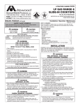
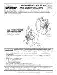
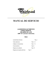
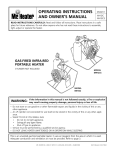
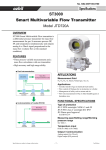
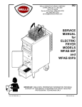
Range Service Manual 2015 1 INTRODUCTION The 2015 edition of the Atwood Range Service Manual is a resource created to help service technicians identify Atwood product by serial number, diagnose service problems and efficiently and effectively process warranty claims. Each of the manuals within this series offers a general overview of the product as well as more specific product information. For the range product within this manual, you will find model identification, sequence of operation, part identification and troubleshooting guides, warranty procedures, flat rate schedules, and replacement part reference charts. Due to the rapidly changing personal computer revolution, we have placed troubleshooting information in a variety of places to make sure that the most accurate information is available. The best place to find the current information about Atwood products is our website: www.atwoodmobile.com. At our website brochures may be downloaded, troubleshooting guides reviewed and the latest information bulletins can be read. In addition, all Atwood Authorized Service Centers are listed on our site, accessible via an easy-to-use search system. Service for all Atwood products is handled our of our Elkhart Indiana location. Should you have any questions regarding our products or the information contained in this manual simply dial our Toll Free 1-866-869-3118. Be sure to have the Model and Serial Numbers when you call. Atwood Service Department 2 TABLE OF CONTENTS INTRODUCTION……………………………………………………………….2 TABLE OF CONTENTS………………………………………………………..3 COOKING APPLIANCE TERMINOLOGY………………………………….4 MODEL NUMBER IDENTIFICATION……………………………………….5 GAS COMPONENT IDENTIFICATION PICTORALS…………………...6-7 SEQUENCE OF OPERATION-MODELS 33, 34, 35, 20 & 21…………...…..8 TROUBLE SHOOTING GUIDE……………………………………… 9-10 INSTALLATION (Ranges & Slide-ins) Cabinet and counter cut-out requirements…………………………….11 Recessed bi-fold cut-out requirement…………………………………..11 Electronic ignition schematic……………………………………………11 Range hood mounting information……………………………………..11 PART DIAGRAMS AND PART NUMBERS (Ranges & Slide-ins) Model 33, RV/CV and RA/CA …………………………………… ... 12-14 Model 34, RV/CV and RA/CA………………………………………15-16 Model 35, RV/CV and RA/CA………………………………………17-18 Bi-Fold Covers and cut-out requirements……………………………..19 INSTALLATION (Drop-ins) Cabinet and counter cut-out requirements…………………………….20 PART DIAGRAMS AND PART NUMBERS (Drop-ins) Covers for DV Drop-in Models………………………………………….20 Model DV20 and DV30………………………………………………….21 WARRANTY……………………………………………………………………22 EXTENDED WARRANTY…………………………………………………….23 ATWOOD RETURN GOODS PROGRAM…………………………………..24 WARRANTY SERVICE REPORT……………………………………………25 FLAT RATE SCHEDULE……………………………………………………..26 INFORMATION NOTICES 3 Cooking Appliance Terminology Terminology ANSI Definition American National Standard for Recreation Vehicle Cooking Gas Appliances Terminology Definition Pilot Orifice A precision drilled thimble shaped component that meters gas flow to the pilot. Burner Electrode The spark source to light top burners with piezo/12 VDC electronic ignition. Replaceable for 33 range series. Regulator Device that reduces the high pressure from the LP bottles to a lower pressure for the appliances Calibration The condition that determines whether the thermostat is registering temperatures properly. Sealed Burner A burner head attached directly to the porcelain main top which prevents spilling to the burner box. Certification Agency (Canadian Standards Association) Standby Pilot The oven pilot that burns constantly and provides the base for the oven burner. Main Burner Orifice A precision drilled thimble shaped component that meters gas flow to the main burner. Thermal Bulb The bulb located in the oven and connected to the thermostat that contains thermal fluid and causes the thermostat to close and open based on the set cooking temperature. Manifold The constantly pressurized tube or pipe that supplies gas to the burner valves. Thermocouple Senses pilot flame for the oven and controls safety valve and thermostat. Oven Thermostat It is the component that regulates the temperature of the oven at the desired cooking temperature and supplies gas for both the standby and heater pilots. Yellow Tipping A burner flame with excessive yellow tipping can be caused by improper gas/air mixture caused by improper alignment, restriction of the orifice, or blockage of the venture tube. Piezo Ignitor An electro-mechanical device that can be used to ignite a top burner. CSA 4 4, 5 5 Range & Oven Gas Components Harper Wyman Harper Wyman Oven Control/Thermostat Harper Wyman Mini Burner Valve Safety Pilot Valve Ranges whose model number is R __8-32 have a complete Harper Wyman range valve system. Cooktops whose model number is R__8-32 to current model have a complete Harper Wyman valve system. Top burners are Harper Wyman and linear Lowest temperature on oven knob is 170 F. Oven control and safety pilot valves are also Harper Wyman. This safety pilot valve is no longer available. Copreci Mercury Free Copreci Oven Thermostat Burner Valve Ranges whose model number is R__33 have a Copreci oven thermostat with Mueller burner valves for the stove top. Lowest temperature on oven knob is 300 F. Slide-ins whose model number is C_3have Mueller burner valves. Pilot assembly is White Rodgers. Orifice Block Pilot Assembly BSI Mercury Free Oven Thermostat Burner Valve Ranges with model numbers R___34 Lowest temperature on oven knob is 300F Burner valve also used in slide-ins(s) with model numbers C_34 and C_20 Pilot Assembly Seven Universe Mercury Free Oven Thermostat Burner Valve Pilot Assembly Ranges with model numbers R___35 and R___21. Lowest temperature on oven knob is 300°F. Burner valve also used in slide-in(s) with model number C_35 and C_21. Gas Regulator—Used in all Atwood Ranges, slide-ins and drop-ins. Seven Universe Regulates gas pressure to nominal 10” W.C. Replaces all previous brands including HarperWyman, Maxitrol, Oara, and BSI. 7 Sequence of Operation—Models 33, 34 and 35 Standard Pressure Regulator— This valve receives up to 13” W.C. gas pressure from regulated LP systems and reduces the pressure to 10” W.C. to the manifold. Manifold—a continually pressurized pipe distributing gas to top burner valves and oven thermostat. Oven Thermostat— supplies gas to the oven pilot, and main burner; regulates oven temperature. Pilot Assembly— consists of a thermocouple and a pilot hood where gas passing through the orifice is directed toward the oven burner pilot holes. The user holds the magnet in initially by pushing the knob in at the “pilot/push/hold” rotation and manually lighting the pilot. After approximately 5 seconds, the thermocouple input will hold the magnet in the open position and the user can release the knob and adjust to the desired temperature. Oven Thermostat - senses oven temperature by means of a thermal bulb located in the upper rear of the oven. The oven control knob is set to the desired temperature calling for heat; the fluid expands in the bulb as the temperature rises, moving the seat in the thermostat from full open to partial open as the desired temperature is reached, thus maintaining the set temperature. The gas is passed from the thermostat to the orifice block in the main burner, entering the burner and igniting from the pilot. Oven Burner—The oven burner remains on once the thermostat is turned on. The size of the flame changes to a high or low flame by the thermostat as regulated by the user setting the knob and the thermostat bulb sensing a satisfied oven temperature. Note: The pilot gas line will remain open as long as the pilot is lighted and the thermocouple senses flame. If the pilot goes out, the magnet will drop out and shut off gas flow to the pilot. Note: Component appearance may vary from model to model. 9 Atwood Cooking Appliance Atwood Mobile Products LLC TROUBLE SHOOTING GUIDE 1120 Nor1h Main Street • Elkhart, IN 46514 PHONE: 574·264 ·2131 FAX: 574·262·2550 INTERNET : http://www atwoodmobile.com Effective: 8/7/13 Guides are only intended for use on Atwood• products lby service technicians who have successfully completed Atwood• training. This guide should be used in conjunction with the appropriate Instruction Manual provided with the product and any applicable Industry Standards. This is not intended to be a complete list. Please direct questions concerning service of Atwood• products to 866-869-3118 before proceeding. CAUSE SOLUTION RANG E PILO T W O N'T LIGHT OR STAY LIT Insufficient gas pressure--------------- Supply valve closed ------------------------- 1. Check for gas leaks and have system pressure checked by qualified LP gas technician. 2. Check gas supply 3. Set pressure to 11”W.C. with two or more gas appliances running. Turn valve on Blocked pilot orifice -------------------------- Clean pilot orifice with toothpick Pilot flame cover out of position ----------- Reposition pilot flame cover, and/or remove carbon and/or coating of carbon BURNER(S) WON’T LIGHT OR STAY LIT Insufficient gas pressure ---------------- Check for gas leaks, have system pressure checked by qualified gas technician Incorrect air/gas mixture------------------ Adjust air shutter if applicable Blocked orifice ------------------------------ Clean with a toothpick BURNER LIGHT BUT FLAME IS TOO SMALL Improper gas pressure------------------------- Check for gas leaks, have system pressure checked by qualified LP gas technician. Improper air/gas mixture --------------- Adjust air shutter if applicable Problem burner valve -----------------------Replace burner valve Blocked orifice ------------------------- Clean with toothpick BURNER FLAME LIFTS OFF BURNER HEAD Gas pressure too high --------------------------- Have system pressure checked by a qualified LP gas technician OVEN BURNER LIGHTS, BUT FLAME REMAINS VERY SMALL AND OVEN HEATS VERY SLOWLY Improper gas pressure----------------------Check for gas leaks, have system pressure checked by qualified LP gas technician. Blocked orifice --------------------------------Clean with alcohol and cotton swab OVEN BURNER FLAM E LIFTS OFF BURNER AND OVEN CYCLES TOO FREQUENTLY Gas pressure too high ---------------------- Have system pressure checked by qualified LP gas technician, or Improper gas mixture OVEN COOKS UNEVENLY AND/OR FOOD BURNS ON THE BOTTOM Poor oven ventilation--------------------------Oven too full for proper circulation- must have 1" clearance in all directions. Ventilation holes in oven bottom (shelf above burner) are covered. Check the top vent (back of range) it must be clear of obstructions. Problem thermostat ------------------------- Replace thermostat. Oven not preheated ----------------------Oven must be preheated at least 15 minutes. Thermo bulb out of position-----------------Thermobulb must be in clip on back of oven – thermobulb should not touch Pans or oven walls. COOKING APPLIANCE - (continued) Effective: 8/7/13 OVEN PILOT OUTAGE Safety Thermal Bulb out of position -------Re-position the safety thermal bulb. Problem thermostat ----------------------------Replace thermostat Blocked oven vent ------------------------------Remove obstruction from vent Incorrect oven burner gas/air mixture------Readjust air YELLOW FLAME TIPS Improper gas-air mixture ---------------------Adjust air shutter if applicable Low gas pressure----------------------------Check gas supply Check for leaks and have the regulator checked Set pressure to 11" water column RA Ranges and Cooktops Improper orifice to burner alignment -------Realign burner head and orifice tube assembly Replace orifice Operation and Trouble Shooting Guide – 33 Series and UP TO LIGHT THE PILOT Turn the oven knob to the pilot position and push in. Light pilot with a lighter. Hold in for at least 30 seconds until pilot is well established. PILOT WILL NOT COME ON Check to see if the gas is turned on. Is there gas in the tanks? Check for blockage of the orifice, pilot assembly, or pilot line. Check for kinks in the pilot line. PILOT WILL NOT STAY ON Hold oven knob ,pilot position, for up to 30 seconds. Check gas supply. Confirm that thermocouple Is fully inserted Into the thermocouple holder. Pilot flame out of position. Pilot flame Is not engulfing thermocouple. Pilot assembly needs to be adjusted so that pilot flame is engulfing thermocouple. Test thermocouple. Thermostat knob is bottoming out on manifold cover (face plate). If knob can’t fully engage, the magnet in the thermostat will not be established. Move manifold out further beyond face plate. THERMOSTAT CALIBRATION The ideal temperature variance is 25 degrees (plus or minus). This means that if the thermostat is set at 350 degrees, the temperature will range between 325 and 375. If the temperature exceeds 50 degrees, plus or minus, check for a kinked capillary tube. 11 Item WEDGEWOOD RV Description ATWOOD RA 1733 2133 1733 2133 30 Door assembly includes handle- black steel 51977 51983 51977 51983 30 Door assembly includes handle – white steel 51978 51984 51978 51984 30 Door assembly includes handle – white glass 51981 51987 51981 51987 30 Door assembly includes handle – black glass 51980 51986 51980 51986 30 Door assembly includes handle – stainless steel 51958 51992 51958 51992 30 Door assembly white handle – white steel 51957 Door-Glass insert – Sm. Black 51881 Door-Glass Insert – Lg Blk Door-Glass Insert – Sm White 51881 51882 51883 Door-Glass Insert – Lg white 31 51957 51882 51883 51884 51884 Oven Door Handle - Black 52025 52025 52025 52025 Oven Door Handle - White 52026 52026 52026 52026 WEDGEWOOD Item RV Description ATWOOD CV RA CA 1733 2133 33 1733 2133 33 1 Grate - Black 56272 56272 56272 57190 - # 57190 - # 57190 - # 2A Grommet (4) # 53009 53009 53009 53009 53009 53009 2B Sealed Grate U-Channel (4) # 57194 57194 57194 3 Top Spring Clip (2) # 51035 51035 51035 51035 51035 51035 4 Range Top Assy – white (obs) 52007 52007 52007 57300 57300 57300 Range Top Assy - black (obs) 52008 52008 52008 57200 57200 57200 Range Top Assy – SST (obs) 56742 56742 56742 57305 57305 57305 5A Burner, Piezo – left rear (WSL) 57205 57205 57205 5A Burner, Matchlit – left rear (obs) 57206 57206 57206 5B Burner, Piezo – center front (WSL) 57201 57201 57201 5B Burner, Matchlit – center front (obs) 57202 57202 57202 5C Burner, Piezo – right rear (WSL) 57203 57203 57203 5C Burner, Matchlit – right rear (obs) 57204 57204 57204 5D Burner, Piezo/Electronic Ignition (obs) 57276 57276 57276 6 Bushing – Burner (3) # 53011 53011 53011 53011 53011 53011 7 Hex Nut (2) # 51004 51004 51004 8 Brass Fitting 52294 52294 52294 52294 52294 52294 9 Pressure Regulator 51062 51062 51062 51062 51062 51062 10 3 – Burner Manifold (after serial number F11040784)(Dbl D) (obs) 57217 57217 57216 57217 57217 57216 3 – Burner Manifold (before serial number F11040783) (obs) 57270 57270 57268 57270 57270 57268 11 Bolt – valve (3) # 57278 57278 57278 57278 57278 57278 12 Bolt – Oven thermostat 57266 57266 57266 57266 13 Valve, Burner- Mini 9000 BTU (after serial number F11030969-R and F11040784-C) (green) (obs) 57218 57218 57218 57218 57218 57218 Valve, Burner – Mini 9000 BTU (before serial number F11030968-R and F11040784-C) (obs) 57252 57252 57252 57252 57252 57252 Valve, Burner – Mini 6500 BTU (after serial number F11030969-R and F11040784-C) (yellow) (wsl) 57213 57213 57213 57213 57213 57213 Valve, Burner – Mini 6500 BTU (before serial number F11030968-R and F11040783-C) (obs) 57251 57251 57251 57251 57251 57213 14 15 Burner Gasket Kit (includes 3) 50140 50140 50140 15A Burner Tube – right rear 57110 57110 57110 15B Burner Tube – left rear 57108 57108 57108 15C Burner Tube – center front 57109 57109 57109 15D Burner Clip, wire (3) # 57198 57198 57198 16 Thermostat, oven control (wsl) 57294 57294 57294 57294 17 Piezo ignitor 56096 56096 56096 56096 56096 56096 18 12V Ignition Module (obs) 57277 57277 57277 57277 57277 57277 19 Valve ignition switch 57262 57262 57262 57262 57262 57262 20 Piezo knob - black 51344 51344 51344 51344 51344 51344 Piezo knob – white 53223 53223 53223 53223 53223 53223 Burner knob – black (3) # 56148 56148 56148 56148 56148 56148 Burner knob – white (3) # 53221 53221 53221 53221 53221 53221 Oven thermostat knob - black 57258 57258 57258 57258 21 22 Oven thermostat knob - white 57291 57291 57291 57291 23 Control panel Assy – w/o Label * * * * * 24 Control panel label * * * * * * 25 Burner box 51687 51687 51687 51687 51687 51687 26 Burner spring clips (3) # 57558 57558 57558 27 Oven can 51969 51970 51969 51970 28 Oven rack 51069 51069 51069 51069 29 Oven shelf 51670 51670 51670 51670 32 Orifice block (obs) 57271 57271 57271 57271 33 Pilot assembly 57247 57247 57247 57247 34 Burner, oven 57275 57275 57275 57275 35 Thermocouple 57274 57274 57274 57274 36 Oven can trim 51975 51975 51975 51975 37 Orifice block plate 57310 57310 57310 57310 N/S Wiring – Harness – Electronic ignition switches 57262 57262 57262 Wiring lead – electronic ignition electrodes 57261 57261 57261 Wiring lead – electronic ignition ground 57260 57260 57260 * N/S Wiring lead – piezo (3) # 57264 57264 57264 57264 57264 57264 N/S Burner electrode (3) # 54800 54800 54800 54800 54800 54800 Continued, N/S Hinge assembly 57557 57559 57557 57559 N/S Kit – Door Seal 51060 51061 5106 51061 N/S Kit – Gas tube Supply Oven (wsl) 57273 57272 57273 57272 N/S Nylon edge guard (4) # 53218 53218 N/S Thermal bulb clip 5134 51364 51364 51364 N/S Towel Bar N/S = Not shown in the illustration OBS = Obsolete 53218 53205 # = Order quantity needed WSL = while supplies last * = Order by model, color, and style 53205 WEDGEWOOD Item RV Description 1734 ATWOOD CV 2134 56272 RA CA 34 1734 2134 34 56272 57190 57190 57190 53009 53009 53009 53009 57194 57194 57194 1 Grate - black 56272 2A Grommet 53009 2B Sealed Grate U-Channel 3 Top Spring Clip 51035 51035 51035 51035 51035 51035 4 Range Top – white, side latches 52014 52014 52014 57534 57534 57534 Range Top – black, side latches 52015 52015 52015 57533 57533 57533 Range Top – stainless steel, side latches 57532 57532 57532 57529 57529 57529 5A Kit, Burner, Sparklite – left (WSL) 57542 57542 57542 5A Kit, Burner, Matchlit – left (WSL) 57543 57543 57543 53009 Continued 5B Kit, Burner, Sparklite – center (WSL) 57540 57540 57540 5B Kit, Burner, Matchlit – center (WSL) 57541 57541 57541 5C Kit, Burner, Sparklite – right (WSL) 57538 57538 57538 5C Kit, Burner, Matchlit – right (WSL) 57539 57539 57539 5D Kit, Burner w/ignitor (OBS) 6 Bushing, Burner 53011 53011 53011 7 Hex Nut 8 Brass Fitting 52294 52294 9 Kit, gas regulator 51062 10 Kit, manifold pipe (OBS) 11 57546 57546 57546 53011 53011 53011 51004 51004 51004 52294 52294 52294 52294 51062 51062 51062 51062 51062 57537 57537 57545 57537 57537 57545 Bolt, mini valve (WSL) 56088 56088 56088 56088 56088 56088 12 Bolt, Oven Thermostat 56125 56125 56125 56125 13 Kit, Valve, Burner – 9000 BTU (OBS) 57244 57244 57244 57244 57244 57244 14 Kit, Valve, Burner – 6500 BTU (OBS) 57239 57239 57239 57239 57239 57239 15A Kit, Burner Tube – right (OBS) 57548 57548 57548 15B Kit, Burner Tube – center (OBS) 57547 57547 57547 15C Kit, Burner Tube – left (OBS) 57549 57549 57549 15D Burner clip, wire 57198 57198 57198 15E Kit, Burner Gasket Kit (includes 3 gaskets) 50140 50140 50140 16 Kit, thermostat oven control 57237 57237 57237 57237 17 Piezo Ignitor 56096 56096 56096 56096 56096 18 Kit, ignition module (OBS) 57550 57550 57550 19 Kit, electronic ignition switch harness 57551 57551 57551 20 Kit, knobs (piezo, burners & oven) 23 56096 57544 57544 57544 57544 57544 57544 Control panel label – w/o label * * * * * * 24 Control panel label * * * * * * 25 Burner box 51687 51687 51687 51687 51687 51687 26 Kit, burner spring clips 57558 57558 57558 27 Oven can 51969 51970 51969 51970 28 Oven rack 51069 51069 51069 51069 29 Oven shelf 51670 51670 51670 51670 30 Door assembly includes handle – black steel 51977 51983 51977 51983 30 Door assembly includes handle – white steel 51978 51984 51978 51984 30 Door assembly includes handle – white glass 51981 51987 51981 51987 30 Door assembly includes handle – black glass 51980 51986 51980 51986 30 Door assembly includes handle – stainless steel 51958 51992 51958 51992 30 Door assembly white handle – white steel 51957 Door – glass insert – sm. black 51881 Door – glass insert – lg. black Door – glass insert – sm. white 51881 51882 51882 51883 Door – glass insert – lg. white 31 51957 51883 51884 51884 Oven door handle - black 52025 52025 52025 52025 Oven door handle – white 52026 52026 52026 52026 32 Kit, oven gas supply assembly 57232 57232 57232 57232 33 Kit, pilot burner assembly 57234 57234 57234 57234 34 Kit, oven burner 57233 57233 57233 57233 35 Kit, thermocouple 57235 57235 57235 57235 36 Oven can trim 51975 51976 51975 51976 N/S Kit, 3/16 pilot gas tube 57236 57236 57236 572356 N/S Kit, piezo ignition leads 57553 57553 57554 57554 57554 N/S Kit, wiring lead – electronic ignition ground 57260 57260 57260 N/S Kit, electronic leads 57556 57556 57556 N/S Kit, oven door hinges N/S Kit, door seal N/S = Not shown in the illustration OBS = Obsolete 57553 57557 57559 57557 57559 51060 51061 51060 56061 # = Order quantity needed WSL = while supplies last * = Order by model, color, and style WEDGEWOOD Item RV Description ATWOOD CV RA CA 1735 2135 35 1735 2135 35 1 Grate - black 52890 52890 52890 57190 57190 57190 2A Grommet 53009 53009 53009 53009 53009 53009 2B Sealed Grate U-Channel 57194 57194 57194 3 Top Spring Clip 51035 51035 51035 51035 51035 51035 4 Range Top – white, side latches 52014 52014 52014 52753 52753 52753 Range Top – black, side latches 52015 52015 52015 52752 52752 52752 Range Top – stainless steel, side latches 51374 51374 51374 52308 52308 52308 Continued 5A Kit, Burner, Sparklite – left 52717 52717 52717 5A Kit, Burner, Matchlit – left 52718 52718 52718 5B Kit, Burner, Sparklite – center 52715 52715 52715 5B Kit, Burner, Matchlit – center 52716 52716 52716 5C Kit, Burner, Sparklite – right 52713 52713 52713 5C Kit, Burner, Matchlit – right 52714 52714 52714 5D Burner head (twist lock) 52750 52750 52750 6 Bushing, Burner 53011 53011 53011 53011 53011 53011 8 Brass Fitting 52166 52166 52166 52166 52166 52166 9 Kit, gas regulator 51062 51062 51062 51062 51062 51062 10 Kit, manifold pipe 52712 52712 52164 52712 52712 52164 11 Bolt, mini valve/ thermostat 52168 52168 52168 52168 52168 52168 13 Kit, Valve, Burner – 9000 BTU 52711 52711 52711 52711 52711 52711 14 Kit, Valve, Burner – 6500 BTU 52710 52710 52710 52710 52710 52710 16 Kit, thermostat oven control 52709 52709 52709 52709 56096 56096 17 Piezo Ignitor 56096 56096 56096 18A Burner tube – left rear 56096 52749 52749 52749 18B Burner tube – center front 52748 52748 52748 18C Burner tube – right rear 52747 52747 52747 19 Burner tube bracket 52803 52803 52803 20 Kit, knobs (piezo, burners & oven) 23 52719 52719 52719 52719 52719 52719 Control panel label – w/o label * * * * * * 24 Control panel label * * * * * * 25 Burner box 51687 51687 51687 51687 51687 51687 27 Oven can 51969 51970 51969 51970 28 Oven rack 51069 51069 51069 51069 29 Oven shelf 51670 51670 51670 51670 30 Door assembly includes handle – black steel 51977 51983 51977 51983 30 Door assembly includes handle – white steel 51978 51984 51978 51984 30 Door assembly includes handle – white glass 51981 51987 51981 51987 30 Door assembly includes handle – black glass 51980 51986 51980 51986 30 Door assembly includes handle – stainless steel 51958 51992 51958 51992 30 Door assembly white handle – white steel 51957 Door – glass insert – sm. black 51881 Door – glass insert – lg. black Door – glass insert – sm. white 51881 51882 51882 51883 Door – glass insert – lg. white 31 51957 51883 51884 51884 Oven door handle - black 52025 52025 52025 52025 Oven door handle – white 52026 52026 52026 52026 32 Kit, oven gas supply assembly 52704 52704 52704 52704 33 Kit, pilot burner assembly 52706 52706 52706 52706 34 Kit, oven burner 52705 52705 52705 52705 35 Kit, thermocouple 52707 52707 52707 52707 36 Oven can trim 51975 51976 51975 51976 N/S Kit, 3/16 pilot gas tube 52708 52708 52708 52708 N/S Kit, piezo ignition leads 57553 57553 57554 57554 N/S Kit, oven door hinges 57557 57559 57557 57559 N/S Kit, door seal 51060 51061 51060 51061 N/S = Not shown in the illustration OBS = Obsolete # = Order quantity needed WSL = while supplies last * = Order by model, color, and style 57553 57554 Item Description DV20 DV30 1 Round Grate 56378 56378 (2) 2 Oval Grate 56379 56379 3 Burner Knob 56380 (2) 56380 (3) 4 Label 56388 56491 5 Top - White 57118 57115 Top - Black 57119 57116 Top – Stainless Steel 57099 57102 6 Right Burner 56385 56483 7 Left Front Burner 56384 56482 8 Left Rear Burner NA 56481 9 Manifold Pipe 56383 56478 10 Regulator 51062 51062 11 Valve 7200 Btu/h 56468 56468 12 Valve 5200 Btu/h 56469 56469 (2) 13 Screw - Valve 56480 (2) 56480 (3) 14 Valve Bracket 56479 (2) 56479 (3) 15 Screw - Burner 51325(4) 51325(5) 16 Screw - Top 56377 (2) 56377 (2) 17 Nylon Washer 52434 (2) 52434 (2) 18 Burner Box 56498 56476 19 Inlet Pipe Grommet 92610 92610 20 Gasket, Valve 56366 (2) 56366 (3) N/S Extension Tube 57181 57182 Note: When installing a pressure gage onto a burner valve remove the top burner by removing the screw used to attach the burner to the burner box. Leak test should only be performed by a qualified technician. 11-2-10 Information Notice NHTSA Recall No. 10E-046 In accordance with the requirements of the National Traffic and Motor Vehicle Safety Act Atwood Mobile Products LLC has determined that a defect which relates to motor vehicle safety exists in certain Atwood Range Ovens manufactured on or before September 20, 2010 with model numbers beginning with RV1735, RV2135 or RA2135. Some of the subject units may contain a small fracture within the line delivering gas to the oven cavity burner. A fracture may allow gas to leak, causing an unexpected build up of gas in the vehicle. This condition can lead to a fire or explosion, and poses an asphyxiation risk. Gas is supplied through this line only when the oven cavity is in use, and thus this condition is not present when the range oven controls are off. Therefore, please ensure that the oven function on these units is not used until they have been certified or repaired; we request your support in ensuring the oven cavity of these units is not lit or used. The range top burners may be used as normal, as long as the oven controls are off To identify if a unit is within the recall period look for model and serial number under the top of the unit. If the range has already been inspected there will be a green check mark in the burner box. If you have any questions or concerns please contact Atwood at 866-869-3118, please have your model and serial number available. Thank you Atwood Service