1
®
B 1-00
B 1-25
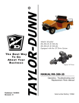
The Best Way
To Go
About Your
Business
Models Inlcuded:
B0-011-00 (B 1-00) Tour Master
B0-011-25 (B 1-25) Carry Master
MANUAL MB-100-00
Operation, Troubleshooting and
Replacement Parts Manual
Published: 12/15/2003
Revision: E
Serial number Starting: 142833
Taylor-Dunn Contact information
Service, Parts, Sales:
Taylor-Dunn has a network of dealers distributed around the globe to support our
vehicles. Information regarding vehicle sales, replacement parts, or service should be
obtained through your local dealer. A dealer locator can be found on the Taylor-Dunn
website at www.taylor-dunn.com.
If you do not have access to the internet, you can call the factory direct at:
01 (714) 956-4040
Feedback regarding this or any Taylor-Dunn vehicle manual can be sent to:
Taylor-Dunn Manufacturing
Attn: Tech Writer
2114 West Ball Road
Anaheim, CA 92804
B2-10 Ambulance
B2-48 With Dump Bed Option
B2-48 with Steel Cab, Foldaway
4-Passenger Seat and Stake Sides
ET 3000
P2-50 30,000 Pound Tow Tractor
ET1-50 Full Size Truck
Section Index
Taylor-Dunn
®
Model B0-011-00 and B0-011-25
Operator and Service Manual Section Index
Introduction
1
Safety Rules and Operating Instructions
2
Lubrication
3
Brakes Service
4
Steering/Front Axle
5
Transaxle Service
6
Motor Service
7
Battery Service
8
Control System Troubleshooting
9
Wire diagram
10
Chargers
Illustrated Parts
11
Appendix A
Special Tools
12
Appendix B
Suggested Torque Values
13
Appendix C
Brake Lining Handling Precautions
14
This quick reference section index guide will assist you in
locating a desired topic or procedure.
Refer to each sectional Table of Contents for the page
number location for specific topics or procedures.
About this manual ......................................... 2
Who Should Read This Manual .................... 2
Responsibilities ............................................ 2
How To Use This Manual .............................. 3
Conventions .............................................................. 3
How to Identify Your Vehicle ........................ 4
Taking Delivery of Your Vehicle ................... 5
B 1-00 shown with optional
luggage rack
Introduction
Table of Contents
INTRODUCTION
ABOUT THIS MANUAL
The purchase of this vehicle shows a belief in high
quality products manufactured in the USA.
Taylor-Dunn®, a leading manufacturer of electric
burden and personnel carriers since 1949, wants to
be sure this vehicle provides years of reliable service.
Please continue to read this manual and enjoy this
high quality Taylor-Dunn® vehicle.
This manual is to serve as a guide for the service,
repair, and operation of Taylor-Dunn® vehicles and is
not intended as a training guide. Taylor-Dunn® has
made every effort to include as much information as
possible about the operation and maintenance of this
vehicle.
Included in this manual are:
RESPONSIBILITIES
Of the Owner...
The owner of this or any Taylor-Dunn® vehicle is
responsible for the overall maintenance and repairs
of the vehicle, as well as the training of operators.
Owners should keep a record of conducted training
and maintenance performed on the vehicle. (OSHA
Regulation, 29 CFR 1910.178 Powered Industrial
Truck Operator Training).
Of the Operator...
The operator is responsible for the safe operation of
the vehicle, preoperational and operational checks
on the vehicle, and the reporting of any problems to
service and repair personnel.
• Vehicle Description
• Safety Rules and Guidelines
• Operational Information
• Operator Responsibilities
• Owner Responsibilities
• Control Operation and Location Information
• Maintenance and Troubleshooting Information
• Standard Parts List
Before servicing, operating, training or performing
maintenance on this or any other Taylor-Dunn® vehicle,
read the appropriate Taylor-Dunn® manual.
®
Each Taylor-Dunn manual references the applicable
models and serial numbers on the front cover.
Please, be aware of all cautions, warnings,
instructions, and notes contained in this manual.
Of the Service Personnel...
The service personnel are responsible for the service
and maintenance of the vehicle. At no time should a
service person allow any untrained personnel to
service or repair this or any Taylor-Dunn® vehicle.
For the purposes of training, a qualified service
person may oversee the repairs or services being
made to a vehicle by an individual in training. At no
time should an untrained individual be allowed to
service or repair a vehicle without supervision. This
manual is not a training guide.
Of the Passengers ...
The passengers are responsible to remain fully
seated, keeping their hands, arms, and legs inside
the vehicle at all times. Each passenger should be
fully aware of the vehicle’s operation. All forms of
recklessness are to be avoided. Do not engage in
horseplay.
WHO SHOULD READ THIS MANUAL
This manual is intended for use by anyone who is
going to operate, own, perform maintenance on,
service, or order parts for this Taylor-Dunn® vehicle.
Each person should be familiar with the parts of this
manual that apply to their use of this vehicle.
Model B 2-10 shown withstake sides
and steel cab with doors options
Page-2
INTRODUCTION
HOW TO USE THIS MANUAL
This manual is organized into five main sections:
INTRODUCTION
This section describes how to use this service manual
and how to identify your vehicle.
Safety Rules and Operating Instructions
This section outlines the safety and operational issues,
location and operation of controls, and the operational
checks that are to be performed on this vehicle. It
also includes various subjects that should be included
in the operator and service training program.
Maintenance Service and Repair
Conventions
Symbols and/or words that are used to define
warnings, cautions, instructions, or notes found
throughout this manual. Refer to the examples below.
A shaded box with the word “Warning” and
the symbol
above denotes a warning. A
warning alerts the reader of a hazard that
may result in injury to themselves or
others. Be sure to follow any instructions
contained within a warning and exercise
extreme care while performing the task.
This section gives specific information on the servicing
of the vehicle and a schedule for maintenance checks.
Electrical and Charger Troubleshooting
This section identifies the troubleshooting procedures
for testing the electrical system and battery charger.
Illustrated Parts
This section provides an illustrated view of various
assemblies. The illustrations are accompanied by
tables identifying the parts.
A shaded box with and the word “Warning”
and the symbol
above denotes a
warning. This warning alerts the reader of
a high voltage hazard that may result in
injury to themselves or others. Be sure to
follow any instructions contained within a
warning and exercise extreme care while
performing the task.
A box with the word “CAUTION” and the
symbol
above denotes a caution and is
used to inform the reader that property
damage may occur. Be sure to exercise
special care and follow any instructions
contained with in a caution.
Note: Alerts the reader to additional
information about a subject.
Model R 3-80 shown equiped with a cargo
box and steel cab with doors options
Model B 2-48 equipped
with the Dump Bed option
Page-3
INTRODUCTION
HOW TO IDENTIFY YOUR VEHICLE
This manual applies to vehicles with the same model and serial numbers listed on the front cover.
These vehicles are designed for driving on smooth surfaces in and around facilities such as industrial plants,
nurseries, institutions, motels, mobile home parks, and resorts. They are not to be driven on public highways.
This vehicle is not designed to be driven on public roads or highways. It is available in maximum
designed speed of 12 mph. Do not exceed the maximum designed speed. Exceeding the maximum
designed speed may result in steering difficulty, motor damage, and/or loss of control. Do not
exceed locally imposed speed limits. Do not tow this vehicle at more than 5 mph.
This vehicle conforms to requirements for Type E vehicles as described in O.S.H.A. Standard Section 29 CFR
1910.178 (Powered Industrial Trucks) and with all applicable portions of the American National Standard for
Personnel and Burden Carriers (ANSI B56.8).
B 1-00
B 1-25
The locations of the model and serial numbers are illustrated below. The location
of the data plate will be in one of two locations:
Page-4
INTRODUCTION
TAKING DELIVERY OF YOUR
VEHICLE
Inspect the vehicle immediately after delivery. Use
the following guidelines to help identify any obvious
problems:
• Examine the contents of all packages and
accessories that may have come in separate
packages with the vehicle.
• Make sure everything listed on the packing
slip is there.
• Check that all wire connections, battery
cables, and other electrical connections are
secure.
What To Do If a Problem is Found
If there is a problem or damage as a result of shipping,
note the damage or problem on the bill of lading and
file a claim with the freight carrier. The claim must be
filed within 48 hours of receiving the vehicle and its
accessories. Also, notify your Taylor-Dunn® dealer of
the claim.
If there is a problem with the operation of the vehicle,
DO NOT OPERATE THE VEHICLE. Immediately
contact your local Taylor-Dunn® distributor and report
the problem. The report must be made within 24 hours
of receiving the vehicle and its accessories.
The only personnel authorized to repair, modify, or
adjust any part of this or any Taylor-Dunn® vehicle is
a factory authorized service technician.
• Check battery cells to be sure they are filled.
• Check the tire pressure, tightness of lug nuts,
and for any signs of damage.
Check the operation of each of the following controls:
• Accelerator
• Brake
• Parking Brake
• Key-Switch
• Forward/Reverse Switch
The only personnel authorized to repair,
modify, or adjust any part of this or any
Taylor-Dunn ® vehicle is a factory
authorized service technician. Repairs
made by unauthorized personnel may
result in damage to the vehicles systems
which could lead to an unsafe condition
resulting in severe bodily injury and/or
property damage. Unauthorized repairs
may also void the vehicles warranty.
• Reverse Beeper (if equipped)
• Front Headlight Switch
• Steering Wheel
• Horn
Model B 2-10 Ambulance
Page-5
Standard* Specifications .................... 2
Safety Rules and Guidelines .............. 3
Driver Training Program ..................... 3
Driver Qualifications. .......................................... 3
Vehicle Controls ................................ 4
Key-Switch ........................................................... 4
Forward-Reverse Switch ..................................... 4
Accelerator Pedal ................................................. 4
Seat Interlock Switch ........................................... 4
Steering ................................................................. 5
Foot Brake Pedal .................................................. 5
Park Brake ............................................................ 5
Horn Button .......................................................... 5
Charger Interlock ................................................. 5
Headlights and Accessories (optional) ............... 6
Hour Meter (2) (optional) .................................... 6
Battery Status Indicator (1) (optional) ................ 6
Vehicle Operational Guidelines .......... 7
Safety Guidelines ................................................. 7
Starting: ................................................................ 7
While driving: ...................................................... 7
Loading and Unloading ....................................... 7
Towing Loads: ...................................................... 7
Parking .................................................................. 8
Towing This Vehicle ............................................ 8
Charging your vehicle ........................ 9
Signet Charger Operation, Model HB Series ..... 9
Signet Charger Operation, Model HBS series ... 9
Lestronic II Charger Operation ........................... 10
New Battery Break in .......................................... 10
Charging Time ...................................................... 10
Storing / Returning to Service ............ 10
Storing Your Vehicle ............................................ 10
Returning to Service ............................................ 10
Periodic Maintenance Checklist ......... 11
Daily Visual inspection: ...................................... 12
Maintenance Guidelines for
Severe Duty Applications ............... 12
Safety Rules and
Operating Instructions
TABLE OF CONTENTS
SAFETY RULES AND OPERATING INSTRUCTIONS
STANDARD* SPECIFICATIONS
ITEM
MODEL
SPECIFICATION
Occupancy
B 1-00
B 1-25
Driver + 3-passengers
Driver + 1-passenger
Dimensions
241L x 112W centimeters (94.875L x 44.25W inches)
Turning Radius
335 Centimeters (132 Inches)
Dry Weight (no batteries)
B 1-00
B 1-25
Min/Max Battery
Weights
Maximum Load
Deck dimensions
336 kg (741 lbs)
334 kg (737 lbs)
174 kg to 195 kg (384 lbs to 432 lbs)
B 1-00
B 1-25
363 kg (800 lbs)
(none)
110.5W x 121.9L Centimeters 43.5W x 48L Inches)
Electrical System
Six 217 Amp Hour, 6 Volt, Lead Acid Batteries,
Solid State Speed Control, 275 Amp
Transmission
Helical Gear, Oil Bath, Automotive Type Hypoid
Differential.
Motor, DC
4.47 kW, (6 Horse Power) intermittant duty
Brakes
Rear Wheel Mechanical Drum , Hand Operated Park Brake
Steering
Automotive Steering 24:1
Tires
5.70 x 8 Load Range B
Frame
Steel Unitized Body, Heavy Duty 16 Gauge Steel,
Diamond Plate
Instrumentation
Key Switch, Horn Button, Forward/Reverse Switch
Light Accessories
Brake Lights
Charger
Built In 1kW, dual voltage (110 - 220 vac) 15-Amp
* - Specifications are subject to change without notice
This vehicle conforms to requirements for Type E vehicles as described in O.S.H.A. Standard Section
1910.178 (Powered Industrial Trucks) and with all applicable portions of the American National Standard for
Personnel and Burden Carriers (ANSI B56.8).
Safety Rules
Page 2
SAFETY RULES AND OPERATING INSTRUCTIONS
SAFETY RULES AND
GUIDELINES
It is the responsibility of the owner of this vehicle to assure
that the operator understands the various controls and
operating characteristics of this vehicle (extracted from
the American National Standards Institute Personnel and
Burden Carriers ANSI B56.8). As well as, following the
safety rules and guidelines outlined in ANSI B56.8 and
listed below.
These vehicles are designed for driving on smooth
surfaces in and around facilities such as industrial plants,
nurseries, institutions, motels, mobile home parks, and
resorts. They are not to be driven on public highways.
This vehicle is not designed to be driven
on public roads or highways. It is available
in maximum designed speed of 12 mph. Do
not exceed the maximum designed speed.
Exceeding the maximum designed speed
may result in steering difficulty, motor
damage, and/or loss of control. Do not
exceed locally imposed speed limits. Do not
tow this vehicle at more than 5 mph.
Refer to Vehicle Operational Guidelines, Safety
Guidelines section for important safety information
regarding operating this vehicle.
DRIVER TRAINING PROGRAM
According to ANSI B56.8, the owner of this vehicle shall
conduct an Operator Training program for all those who
will be operating this vehicle. The training program shall
not be condensed for those claiming to have previous
vehicle operation experience. Successful completion of
the Operator Training program shall be required for all
personnel who operate this vehicle.
The Operator Training program shall include the
following:
• Operation of this vehicle under circumstances
normally associated with your particular environment.
•
•
•
•
Emphasis on the safety of cargo and personnel.
All safety rules contained within this manual.
Proper operation of all vehicle controls.
A vehicle operation and driving test.
Driver Qualifications.
Only those who have successfully completed the
Operator Training program are authorized to drive this
vehicle. Operators must possess the visual, auditory,
physical, and mental ability to safely operate this vehicle
as specified in the American National Standards Institute
Controlled Personnel and Burden Carriers ANSI B56.8.
The following are minimum requirements necessary to
qualify as an operator of this vehicle:
• Demonstrate a working knowledge of each control.
• Understand all safety rules and guidelines as
Read and follow all of the guidelines listed
below. Failure to follow these guidelines
may result in severe bodily injury and/or
property damage.
Before working
on a vehicle:
presented in this manual.
•
•
•
•
Know how to properly load and unload cargo.
Know how to properly park this vehicle.
Recognize an improperly maintained vehicle.
Demonstrate ability to handle this vehicle in all
conditions.
1. Make sure the key-switch is in the “OFF”
position, then remove the key.
2. Place the forward-reverse switch in the
center “OFF” position.
3. Set the park brake.
4. Place blocks under the front wheels to
prevent vehicle movement.
5. Disconnect the main positive and
negative cables at the batteries.
Safety Rules
Page 3
SAFETY RULES AND OPERATING INSTRUCTIONS
VEHICLE CONTROLS
Key-Switch
A key-switch, located at the front of the instrument panel,
turns on the vehicle. Rotate the key clockwise to turn
the vehicle on, counterclockwise to turn the vehicle off.
The key-switch should be in the “off” position whenever
the operator leaves the driver's seat.
This switch is also designed to secure and disable the
vehicle. The key can only be removed when the keyswitch is in the off position.
Forward-Reverse Switch
The forward-reverse switch, located on the instrument
panel, determines the direction of travel of the vehicle.
Push the top of the switch to make the vehicle travel
forward. Push the bottom of the switch to travel in
reverse.
DO NOT SHIFT from forward to reverse or vice-versa
while the vehicle is in motion. Make sure the vehicle is
completely stopped before shifting.
The forward-reverse switch should be in the center “off”
position, with key-switch off and the park brake set
whenever the operator leaves the driver's seat.
Accelerator Pedal
The accelerator pedal is located to the right of the brake
pedal. It controls the speed of the vehicle and operates
the same way as the accelerator pedal in an automobile.
Depress the pedal to increase speed and release the
pedal to decrease speed.
Seat Interlock Switch
A switch located under the driver's seat disables the vehicle when the driver leaves the seat. The driver must be
seated for the vehicle to operate.
The switch is a part of the vehicle safety system. It should not be relied upon as the sole safety feature used to
disable or disengage this vehicle.
Whenever the driver leaves the seat, they should turn the key-switch off, place the forward-reverse switch in the
center off position, and set the park brake.
Safety Rules
Page 4
SAFETY RULES AND OPERATING INSTRUCTIONS
Steering
The steering wheel and steering system is an automotive
type. To turn right, turn the steering wheel clockwise. To
turn left, turn the steering wheel counter clockwise.
Foot Brake Pedal
The foot brake pedal, located to the right of the steering
column, is for operation with the right foot only. It works
the same as the brake in an automobile. Applying
pressure to the brake pedal slows the vehicle according
to the amount of pressure applied. Relieving pressure
from the pedal releases the braking action.
Park Brake
The parking brake is part of the foot brake pedal.
To set the parking brake, push down on the lower half of
the brake pedal until the pedal locks in the down position.
To release the park brake, apply pressure on the upper
half of the brake pedal until the pedal disengages from
the lock position.
Set park brake
Horn Button
The horn button is located on the floor to the left of the
steering column. Depress the button to sound the horn,
release it to turn it off.
Charger Interlock
The charger interlock is designed to disable the vehicle from being driven while the AC charger cord is plugged into
a functioning power source.
NOTE: The interlock shown is mounted external of the charger. Some vehicles may have the interlock built into the
charger.
Safety Rules
Page 5
SAFETY RULES AND OPERATING INSTRUCTIONS
Headlights and Accessories (optional)
The headlight switch is located to the rear of the instrument panel,
between the seats. An accessory switch, if any, is adjacent and to the
left of the light switch.
Head light switch location
Accessory switch location
Hour Meter (2) (optional)
The hour meter is located below the battery status indicator. This
tracks the number of hours the vehicle has been in operation.
Battery Status Indicator (1) (optional)
The battery status indicator is located above the hour meter.
The normal operating range is in the green zone. The vehicle
needs charging if it is in the yellow zone. If it is in the red zone,
the vehicle should be taken out of service immediately to be
charged.
Safety Rules
Page 6
SAFETY RULES AND OPERATING INSTRUCTIONS
VEHICLE OPERATIONAL
GUIDELINES
Safety Guidelines
• Only qualified and trained operators may drive this
vehicle.
• Drive only on level surfaces or on surfaces having
While driving:
• Slow down and sound the horn to warn pedestrians
or when approaching a corner or other intersection.
• No reckless driving.
• Do not drive this vehicle on steep inclines or where
prohibited.
• Immediately report any accidents or vehicle problems
to a supervisor.
an incline of no more than 10% (5.6 degrees).
• Drive slowly when making a turn, especially if the
ground is wet or when driving on an incline.
• This vehicle may overturn easily if turned sharply or
when driven at high speeds.
• Observe all traffic regulations and speed limits.
• Keep all body parts (head, arms, legs) inside this
vehicle while it is moving.
• Keep the vehicle under control at all times.
• Yield right of way to pedestrians, ambulances, fire
trucks, or other vehicles in emergencies.
• Do not overtake another vehicle at intersections, blind
spots, or other dangerous locations.
• Do not drive over loose objects, holes, or bumps.
• Yield right of way to pedestrians and emergencies
vehicles.
• Stay in your driving lane under normal conditions,
maintaining a safe distance from all objects.
• Keep a clear view ahead at all times.
Starting:
Perform all necessary vehicle preparation steps,
inspections, or maintenance before operating this
vehicle.
1. Make sure the forward-off-reverse witch is in the
center “OFF” position.
Loading and Unloading
• Do not carry more than the maximum number of
passengers allowed for this vehicle.
• Do not exceed the cargo load capacity.
• Do not load cargo that can fall off.
• Be careful when handling cargo that is longer, wider,
or higher than this vehicle, be sure to properly secure
all loads.
Towing Loads:
• Do not exceed the towing capacity of the tractor.
• Do not exceed the load capacity of the trailer. Refer
to documentation supplied with your trailer for
information regarding load capacity of the trailer.
• Make sure all loads are securely tied down. Refer to
documentation supplied with your trailer for
information regarding attaching loads to the trailer.
• Do not back up when towing more than one trailer.
• Drive slowly when towing loads with a high center of
gravity.
• When turning, be sure to allow for “corner cutting” of
the trailer.
• Allow for longer stopping distances when towing
heavy loads.
• Allow for longer stopping distances when driving
down a grade.
2. Set the parking brake.
3. Hold down the foot brake.
4. Rotate the ON-OFF switch to the “ON” position.
5. Release the parking brake.
6. Release the foot brake.
7. Slowly depress the accelerator pedal.
Safety Rules
Page 7
SAFETY RULES AND OPERATING INSTRUCTIONS
Parking
Before leaving the vehicle:
• Set the parking brake.
• Set the forward-off-reverse switch to the ` “OFF”
position.
• Rotate the start switch to the “OFF” position.
In addition:
• If parking this vehicle on an incline, turn the wheels
to the curb, or block the wheels.
• Do not block fire aisles, emergency equipment,
stairways, or exits.
Towing This Vehicle
This vehicle is equipped with regenerative
braking. Follow these steps before towing
this vehicle.
1. To tow this vehicle the start switch must
be in the “OFF” position.
2. Place the forward/reverse switch in the
center “OFF” position.
Failure to follow these instructions may
result in damage to the vehicle.
To tow this vehicle, attach a tow strap to the front bumper
tow-bar.
NOTE: If the vehicle is equipped with an automatic
electric brake, do not tow the vehicle with
the drive wheels on the ground.
Use another driver to steer this vehicle while it is being
towed. Be sure the driver uses the brakes when the
towing vehicle slows or stops. Do not tow the vehicle
faster than 5 m.p.h. or its maximum designed speed,
whichever is lower.
If at all possible, this vehicle should be placed on a carrier,
rather than towing.
Safety Rules
Page 8
The park brake should be disabled for
servicing or towing procedures only. Do not
operate the vehicle while the automatic
park brake is disabled. Operating the
vehicle with the automatic park brake
disabled could lead to severe bodily injury
and/or property damage.
SAFETY RULES AND OPERATING INSTRUCTIONS
CHARGING YOUR VEHICLE
Explosive mixtures of Hydrogen gas are
present within battery cells at all times. Do
not work with or charge battery in an area
where open flames (including gas furnace
or water heater pilots), sparks, cigarettes,
or any other sources of combustion are
present. Always provide ample ventilation
in rooms where batteries are being charged.
Failure to do so may result in severe bodily
injury and/or property damage.
Battery electrolyte is poisonous and
dangerous. It contains sulfuric acid. Avoid
contact with skin eyes or clothing. Wear
rubber gloves and safety glasses while
servicing batteries. DO NOT INGEST! This
may result in severe bodily injury.
The key switch must be in the “OFF” position
when charging the batteries. Failure to turn
the key switch “OFF” may result in damage to
the vehicles electrical system.
Signet Charger Operation, Model HB Series
The Signet ® HB series
chargers use a semiautomatic charging system.
The charger will turn itself
ON when the AC power cord
is connected to the AC
power source and turn itself
Typical Signet® Built In
OFF when the batteries are
fully charged. Refer to the data plate on the charger for
the voltage and type power required for the charger.
There is a series of LED’s on the faceplate of the charger
that serve two functions:
1. Status of charge. The LED’s will display an
approximate percent of charge during the charging
cycle. Refer to the table below.
2. Error condition. All three
LED’s flashing is an
indication of a charging
problem (charger will also
be beeping). Refer to the
Charger Troubleshooting
section for information on
error codes.
Signet Charger Operation, Model HBS series
The Signet ® HBS series
chargers are fully automatic.
The charger will turn itself ON
when the AC power cord is
connected to the AC power
source and turn itself OFF
when the batteries are fully
charged. Once the charge
cycle is complete, the charger
will continue to monitor the
batteries. If the battery voltage
Typical Signet® HBS
drops during storage, the charger will start a new cycle
to keep the batteries fully charged.
NOTE: If the charger restarts during a short time period
of storage, then it would be an indication of
faulty batteries.
Refer to the data plate on the charger for the voltage and
type power required for the charger.
There is a series of LED’s on the faceplate of the charger
that serve two functions:
1. Status of charge. The STATUS LED’s will display
an approximate percent of charge during the
charging cycle. Refer to the table below.
Charging State
LED1
LED2
LED3
0 to 50%
Blinking
OFF
OFF
50% to 75%
ON
Blinking
OFF
75% to 100%
ON
ON
Blinking
Cycle complete
ON
ON
ON
2. Error condition. The FAULT LED flashing is an
indication of a charging problem (charger may also
be beeping). Refer to the Charger
Troubleshooting section for information on error
codes.
Safety Rules
Page 9
SAFETY RULES AND OPERATING INSTRUCTIONS
Lestronic II Charger Operation
Charging Time
The Lestronic II® charger is a semi-automatic charging
system. The charger will turn itself ON when the AC power
cord is connected to the AC power source and turn itself
OFF when the batteries are fully charged. Refer to the
data plate on the charger for the voltage and type power
required for the charger. When plugged in, the charger
assumes that the batteries require charging and will
charger for a minimum of approximately 4-hours. This
charger should not be plugged in until the batteries are
discharged beyond 50% or the batteries may be
overcharged..
Average charging time is 8 to 10-hours. The time required
to fully charge your batteries will vary depending on:
• Capacity of the batteries, higher capacity requires
longer charge time.
• Output of the charger, higher output requires less
charge time.
• Depth of discharge, the deeper a battery is
discharged, the longer it takes to charge.
• Temperature, low temperatures require longer charge
time.
New Battery Break in
New batteries require a break in period of up to 40-cycles.
The batteries will not have their full capacity during this
break in period and may require longer charging times.
To obtain the maximum battery life:
Charge the batteries only after they reach a normal
discharge as indicated on the Battery Status Indicator
(BSI). Failure to follow this guideline could result in the
batteries entering an overcharge state, which will reduce
the life of the batteries. If you find it necessary to charge
the batteries before they are completely discharged we
recommend waiting until they are discharged a minimum
of 25% to reduce the possibility of overcharging. Refer to
Vehicle Controls in this section for information on how to
read the BSI.
Do not discharge the batteries beyond a normal discharge
as indicated on the BSI. Refer to Vehicle Controls in this
section for information on how to read the BSI.
Check the battery electrolyte once a week. Do not charge
the batteries if the battery electrolyte is low. Charging
when the electrolyte is low will damage the batteries and
shorten their life-span. Only authorized personnel should
perform battery maintenance including maintaining the
battery electrolyte level. Refer to Section Maintenance,
Service and Repair for battery maintenance
information.
Do not interrupt the charging cycle. When the charger is
plugged in, allow it to turn off before disconnecting.
Interrupting the charging cycle could lead to overcharging
or discharging the batteries too deep. Both circumstances
will shorten the life of the batteries.
It is not unusual for charge times to exceed 15-hours,
especially with new batteries.
Charging time is limited to 20-hours (HBS) or 18-hours
(HB). A fault will occur if the charging time exceeds the
20-hour limit.
STORING / RETURNING TO
SERVICE
Both storing your vehicle and returning it to service should
only be performed by authorized personnel.
Storing Your Vehicle
• Clean the batteries, then fill and charge before putting
the vehicle in storage. Do not store batteries in a
discharged condition.
• Lube all grease fittings.
• Clean, dry, and check all exposed electrical
connections.
• Inflate tires to proper pressure (if applicable).
• For extended storage, the vehicle should be elevated
so that the tires do not touch the ground.
If stored for a prolonged period, the batteries should be
charged as follows:
Returning to
Service
• Check
the
battery’s state
of charge and
charge
if
required.
• Perform ALL
Storage
Charging Interval
Temperature
(months)
(F)
Over 60
1
Between 40 and 60
2
Below 40
6
maintenance checks in the periodic checklist.
• Remove any blocks from the vehicle and/or place the
vehicle down on to the ground.
• Test drive before putting into normal service.
Safety Rules
Page 10
SAFETY RULES AND OPERATING INSTRUCTIONS
PERIODIC MAINTENANCE CHECKLIST
Weekly Monthly
(20hrs) (80hrs)
Maintenance Item2,3
Check Condition of Tires and
Tire Pressure
l
Check All Lights, Horns,
Beepers and Warning Devises
l
Check and Fill Batteries
l
Check Brake System
l
Check Steering System
l
Check for Fluid Leaks
l
Quaterly
(250hrs)
Lubricate Vehicle
l
Clean and Tighten All Wire
Connections
l
Wash and Service Batteries
l
Semi Annual
(500hrs)
Check Park Brake
l
Check Motor Brushes and
Blow Out Motor
l
Check Front Wheel Bearings
l
Check Rear Axle Oil
l
Annualy
(1000hrs)
Change Rear Axle Oil
l
Check and Tighten all Nuts and
Bolts
l
Clean and Repack Front Wheel
Bearings
l
1, 2, 3 - See notes on following pages.
Only properly trained and authorized technicians should perform
maintenance or repairs to this vehicle. Repairs or maintenance by
improperly trained or unauthorized personnel could cause improper
operation of the vehicle or premature failure of components resulting
in severe bodily injury and/or property damage.
Safety Rules
Page 11
SAFETY RULES AND OPERATING INSTRUCTIONS
Daily Visual inspection:
Tire condition and pressure.
External frame damage (body).
Operation of all lights and warning alarms and/or horns.
Smooth and proper operation of all controls such as but not limited to:
•
•
•
•
•
Accelerator pedal, Brake pedal, Steering, Parking brake, etc.
Proper operation of all locking devises such as but not limited to:
Tool box, Removable battery trays, Cargo box, Cab doors, etc.
Proper operation of all interlocking switches such as but not limited to:
Key switch, Seat interlock switch, Charger interlock switch, etc.
Inspect for leaking fluids or grease.
MAINTENANCE GUIDELINES FOR
SEVERE DUTY APPLICATIONS
1. This maintenance checklist is based on the average application. If the vehicle is operated under
“severe conditions”, service procedures should be conducted more frequently than specified. The
frequency of service under severe conditions is determined by the use of the vehicle. The owner/
operator must evaluate the operating environment to determine the increase in maintenance frequency.
In addition, the whole vehicle should be inspected monthly for signs of damage. The damage must be
repaired immediately.
The following list is meant as a guide and is not all-inclusive of a “severe duty” application.
• Extreme temperature.
• Bumpy, dusty, or ill maintained roads.
• Excessively wet areas.
• Corrosive or contaminated areas.
• Frequent loading of vehicle at/near capacity.
• Use on multiple shifts.
2. Any deficiencies found during an inspection should corrected before the vehicle is returned to service.
Safety Rules
Page 12
OR - DU
N
ine s s
Bu s
To
ur
a
Th e B e s t W
y
YL
R
A
N
T
3. Battery water level should be inspected on a weekly schedule.
Go A b o u t
Yo
Section 3 -
Maintainance and Repair
TABLE OF CONTENTS
Maintenance Guidelines ............................... 2
Severe Duty Guidelines ............................................ 3
Lubrication Chart .......................................... 4
Troubleshooting Guide ................................ 5
Mechanical Drum Brakes .............................. 6
Auto-Adjust Brake Mechanism
Theory of Operation ............................... 7
Inspecting the Auto Adjuster ..................................... 8
Replacing the Brake Shoes ....................................... 10
Replacement and Inspection of Park Brake Lock ..... 12
Brake Pedal Linkage ..................................... 13
Adjusting the Brake Pedal Linkage ........................... 14
Front Axle and Steering ................................ 15
Front Axle Removal and Installation .......................... 16
Aligning the Front End ................................. 17
Adjusting the Toe-In .................................................. 17
Centering the Steering Gear ..................................... 18
Repairing the Front Axle ............................... 19
Steering Yoke/Bushings ............................................ 19
Ball Joints ................................................................. 20
Wheel Bearings ........................................................ 21
Removal and Installation of the
Steering Gear Assembly ........................................... 23
Steering Gear Adjustment ............................ 25
Input Shaft Endplay ................................................... 25
Gear Lash ................................................................. 26
Steering Gear Disassembly and Repair ....... 27
Exploded View of Steering Gear ............................... 30
Drive Service ................................................. 31
Removing the Rear Axles .......................................... 31
Servicing the Differential ........................................... 32
Changing the Differential Oil ..................................... 35
Motor Removal .......................................................... 37
Armature Inspection .................................................. 38
Replacing the Brushes .............................................. 39
Inspecting the Motor Brushes ................................... 41
Battery ........................................................... 42
Cleaning .................................................................... 42
Servicing ................................................................... 43
Battery Storage ......................................................... 44
MB-100-00
MAINTENANCE GUIDELINES
Allow only qualified and authorized personnel to maintain, repair, adjust, or inspect the vehicle.
• Before starting any repairs or maintenance, immobilize
the vehicle.
• Turn the key switch “off” and remove the key.
• Set the park brake.
• Place the forward-reverse switch in the center “off”
postion.
• Disconnect both of the main battery leads before
working on or disconnecting any electrical component
or wire.
• Block the chassis with jack stands before working under
a raised vehicle.
• Conduct vehicle performance checks in an authorized
area where safe clearance exists.
• Tighten all nuts and bolts in accordance with the
“Recommended Torque Values Chart” found in
Appendix C.
• Avoid fire hazards and have fire protection equipment
present in the work area. Do not use an open flame to
check level or leakage of battery electrolyte. Do not
use open pans of fuel or flammable fluids for cleaning
parts.
• Ventilate the work area properly.
Section 3
Page 2
MB-100-00
• Brakes, steering mechanisms, speed and directional
control mechanisms, warning devices, lights,
governors, guards, and safety devices should be
regularly inspected and maintained.
• Inspect and maintain battery limit switches, protective
devices, electrical conductors and connections in
conformance with Taylor-Dunn’s recommended
procedures.
• Keep the vehicle in clean condition to minimize fire
hazards. Be sure to detect any loose or defective parts.
Severe Duty Guidelines
If the vehicle is operated under “severe conditions,” service procedures should be conducted more
frequently than specified in the “Periodic Maintenance Checklist.” The frequency of service under severe
conditions is determined by the use of the vehicle. The owner/operator must evaluate the operating
environment to determine the increase in maintenance frequency.
In addition, the whole vehicle should be inspected monthly for signs of damage. The damage must be
repaired immediately.
The following list is meant as a guide and is not all-inclusive of a “severe duty” application:
• In extreme temperature.
• On bumpy, dusty, or ill maintained roads.
• In excessively wet areas.
• In corrosive or contaminated areas.
• Frequent loading of vehicle at/near capacity.
• On multiple shifts.
Section 3
Page 3
MB-100-00
LUBRICATION CHART
3
1
1
3
2
2
3
3
4
4
5
5
6
#
Descriptio n
Lubricant Type
1
Front Leaf Springs
General P urpose Grease
2
K ing Pin
General P urpose Grease
3
Ball Joints
General P urpose Grease
4
Front W heel Bearings
H igh Temperature W heel Bearing Grease
5
Rear Leaf Springs
General P urpose Grease
6
Drive Drain Plug
10 oz. 30 wt. Motor O il
Section 3
Page 4
MB-100-00
TROUBLESHOOTING GUIDE
Symptom
Steering Pulls in One Direction
Probable Cause
Front End Out of Alignment
Low Tire Pressure
Dry Lube Points in Steering Linkage
Damaged King Pin/Ball Joint
Hard Steering
Low Tire Pressure
Steer Gear Needs Adjusting
Steer Gear Needs To Be Replaced
Worn Ball Joints
Mis-Adjusted or Worn Steering Gear
Excessive Steering Play
Loose Steering Linkage
Steer Gear Needs Adjusting
Steer Gear Needs To Be Replaced
Brakes or Parking Brakes Dragging
Worn Drive Gears
Lack of Power or Slow Operation
Front End Out of Alignment
Defective Speed Control or Motor
Defective Batteries or Charger
Worn Drive Gears or Bearings
Abnormal Noise
Worn Front /Rear Axle Bearings
Loose Lug Nuts
Motor Bearings Worn
Oil Leak in Rear Bearing Area
Brake Pedal Low
Rear Wheel Bearing and/or Gasket Failed
Drive Over Filled
Brake Worn (1/16" Wear Limit)
Brakes Out of Adjustment
Brake Worn (1/16" Wear Limit)
Braking Power Low
Brake Pads Contaminated with Fluid
Brake Pedal Linkage Binding
Brakes Out of Adjustment
Section 3
Page 5
MB-100-00
MECHANICAL DRUM BRAKES
Taylor-Dunn does not currently supply asbestos fiber-brake pads/
shoes with any vehicle. However, there is the possibility that the
original brake pads/shoes were replaced with aftermarket pads/shoes
containing asbestos. Since this possibility does exist, the brake pads/
shoes should be handled as if they do contain asbestos.
Never use compressed air or dry brush to clean the brake assemblies.
Use an OSHA approved vacuum cleaner or any alternate method
approved by OSHA to minimize the hazard caused by airborne asbestos
fibers and brake dust.
Do not grind, sand, break, or chisel the brake pads/shoes, as this will
cause unnecessary dust, possibly releasing asbestos fibers in the air.
Always wear protective clothing and a respirator when working on the
brake pads/shoes or their associated components.
Inhaled asbestos fibers have been found to cause cancer and respiratory
diseases.
Do not drive the vehicle if any worn or broken part is detected in any
part of the brake system. The cause of the damage must be repaired
immediately.
Section 3
Page 6
MB-100-00
AUTO-ADJUST BRAKE MECHANISM
THEORY OF OPERATION
The auto-adjust mechanism is located on the bottom of the brake assembly and accessible through the
oval slot in the brake drum. As the brake pad material wears down, the distance the brake shoes travel
to engage the brake drum becomes longer. When the travel becomes long enough, the brake lever
engages the auto-adjust lever and causes it to index a tooth on the star wheel adjuster. This rotates the
adjuster, which decreases the travel needed for the brake shoes to engage the brake drum.
NOTE: The only time the brakes should be manually adjusted is when an
internal component of the braking system has been removed.
NOTE: The brakes will not require manual adjustment if any part of the
external mechanical linkages or cables have been removed.
NOTE: The symptom of a low brake pedal may indicate that the auto
adjuster is not working or the brake cable is not adjusted properly.
Remove the vehicle from service and repair the brakes.
NOTE: The brake adjustment is inside of the left and right brake. Do not
adjust the brake by means of the brake cables as this will cause
misoperation of the brakes. If you hear a single “clunking” noise
while braking it may be due to misadjustment of the brake cables
or linkage. Refer to Replace Brake linkages/Cables for information
regarding proper adjustment of the cables and linkages.
Adjusting the brakes by means of the brake cables could cause a
hard brake pedal with little or no braking power. This could cause
loss of control of the vehicle resulting in severe bodily injury and /or
property damage.
Section 3
Page 7
MB-100-00
Inspecting the Auto Adjuster
1. Make sure the key-switch is in the “OFF” position, then remove
the key.
2. Place the forward-reverse switch in the center “OFF” position.
3. Set the park brake.
4. Place blocks under the front wheels to prevent vehicle movement.
5. Disconnect the main positive and negative cables at the batteries.
6. Raise the rear of the vehicle and support with jack stands.
Always use a lifting strap, hoist, and jack stands, of adequate capacity
to lift and support the vehicle. Failure to use lifting and support devices
of rated load capacity may result in serious bodily injury.
7. Using the appropriate procedure, remove the brake
drum.
8. Release the park brake.
9. Back off the auto adjuster star wheel one or two
turns.
10. Reinstall the brake drum and depress the bake
pedal.
11. As the brake pedal is depressed, the auto adjuster
indexes the star wheel adjuster causing a click.
12. Lower the vehicle.
13. Reconnect the main positive and negative at the
batteries.
14. Remove the blocks from behind the wheels.
Brake assembly
15. Test drive the vehicle.
Section 3
Page 8
MB-100-00
This page intentionaly left blank
Section 3
Page 9
MB-100-00
Replacing the Brake Shoes
1. Make sure the key-switch is in the “OFF” position, then remove
the key.
2. Place the forward-reverse switch in the center “OFF” position.
3. Set the park brake.
4. Place blocks under the front wheels to prevent vehicle movement.
5. Disconnect the main positive and negative cables at the batteries.
6. Raise the rear of the vehicle and support with jack stands.
Always use a lifting strap, hoist, and jack stands, of adequate capacity
to lift and support the vehicle. Failure to use lifting and support devices
of rated load capacity may result in serious bodily injury.
7. Using the appropriate procedure, remove the brake
drum.
8. Release the park brake.
9. Remove the tension springs.
10. Remove the hold down springs.
11. Remove the auto-adjust lever spring.
12. Apply this procedure in reverse order to install the
new brake shoes.
NOTE: Be sure all the parts are thoroughly
cleaned.
NOTE: Be sure that the anchor points on the
brake shoes are given a light coat of
hi-temp grease.
13. Lower the vehicle.
14. Reconnect the main positive and negative at the
batteries.
15. Remove the blocks from behind the wheels.
16. Test drive the vehicle.
Do not allow grease to
contact any of the braking
surfaces. Braking surfaces
contaminated with grease
may cause the brakes to fail
resulting in property damage
and/or severe bodily injury.
Section 3
Page 10
MB-100-00
This page intentionaly left blank
Section 3
Page 11
MB-100-00
Replacement and Inspection of Park Brake Lock
1. Make sure the key-switch is in the “OFF” position, then remove
the key.
2. Place the forward-reverse switch in the center “OFF” position.
3. Set the park brake.
4. Place blocks under the front wheels to prevent vehicle movement.
5. Disconnect the main positive and negative cables at the batteries.
6. Raise the rear of the vehicle and support with jack stands.
Always use a lifting strap, hoist, and jack stands, of adequate capacity
to lift and support the vehicle. Failure to use lifting and support devices
of rated load capacity may result in serious bodily injury.
7. With the brake pedal in its fully extended
position, remove the 1/2” bolt and locknut
from under the pedal.
Brake
Pedal
Park
Brake
Lock
8. Remove the pedal and park brake lock
assembly from the brake arm.
Brake
Arm
1/2”
Bolt
9. Install a new pedal and park brake lock
assembly.
Always use new locknuts. Locknuts become less effective if used more
than once. Failure to replace the locknuts may result in the locknuts
or bolts coming loose causing property damage and/or severe bodily
10. Lower the vehicle.
11. Reconnect the main positive and negative at the batteries.
12. Remove the blocks from behind the wheels.
13. Release the park brake and test drive the vehicle.
Wear Limits:
If the park brake lock does not catch, or it slips easily, it must be replaced.
Press on the lower half of the pedal. If the park brake lock engages with little effort on the upper
most notch, check the linkage adjustments and adjust as needed.
Section 3
Page 12
MB-100-00
BRAKE PEDAL LINKAGE
Section 3
Page 13
MB-100-00
Adjusting the Brake Pedal Linkage
1. Make sure the key-switch is in the “OFF” position, then remove
the key.
2. Place the forward-reverse switch in the center “OFF” position.
3. Set the park brake.
4. Place blocks under the front wheels to prevent vehicle movement.
5. Disconnect the main positive and negative cables at the batteries.
6. Raise the front of the vehicle and support with jack stands.
Always use a lifting strap, hoist, and jack stands, of adequate capacity
to lift and support the vehicle. Failure to use lifting and support devices
of rated load capacity may result in serious bodily injury.
7. Release the park brake.
8. Loosen the jam nut on the brake linkage.
9. Tighten the adjusting bolt until most of the slack is removed
from the cables.
NOTE: There should be some slack in the brake
cables. Do not overtighten the brake cables.
Overtightening of the adjusting bolt and the
cables will result in brake drag and premature
failure of the brake shoes.
Jam Nut
Clevis
Adjusting
Bolt
10. Tighten the jam nut against the clevis and lower the vehicle.
11. Check the brake pedal to see that the park brake lock engages with medium pressure on the lower
half of the pedal.
12. Check the travel of the brake pedal. It should have about 1/2” of travel before it engages the brakes.
13. Lower the vehicle.
14. Set the park brake.
15. Reconnect the main positive and negative at the batteries.
16. Remove the blocks from behind the wheels.
17. Test drive the vehicle.
Section 3
Page 14
MB-100-00
FRONT AXLE AND STEERING
Front
Axle
(ref)
LEFT SIDE SHOWN
Spring Leaf
Axle Weld
Right Front
Axle Yoke
Left Front
Axle Yoke
Axle Spring
Plate
Tie Rod
Section 3
Page 15
MB-100-00
Front Axle Removal and Installation
1. Make sure the key-switch is in the “OFF” position, then remove
the key.
2. Place the forward-reverse switch in the center “OFF” position.
3. Set the park brake.
4. Place blocks under the front wheels to prevent vehicle movement.
5. Disconnect the main positive and negative cables at the batteries.
6. Raise the front of the vehicle and support with jack stands.
Always use a lifting strap, hoist, and jack stands, of adequate capacity
to lift and support the vehicle. Failure to use lifting and support devices
of rated load capacity may result in serious bodily injury.
7. Remove both front wheels.
8. Remove the tie rod from the steering yokes.
9. Remove the bolts holding the leaf springs to the
frame.
Steering Yoke
NOTE: Support the axle with additional stands.
10. Remove the axle from the vehicle.
NOTE: If the leaf springs were removed from
the axle, be sure to leave the u-bolts
loose until the axle is mounted to the
frame.
Ball Joint
11. Install in reverse order.
12. Lower the vehicle.
13. Reconnect the main positive and negative at the batteries.
14. Remove the blocks from behind the wheels.
15. Release the park brake and test drive the vehicle.
Section 3
Page 16
MB-100-00
ALIGNING THE FRONT END
Adjusting the Toe-In
1. Make sure the key-switch is in the “OFF” position, then remove
the key.
2. Place the forward-reverse switch in the center “OFF” position.
3. Set the park brake.
4. Place blocks under the front wheels to prevent vehicle movement.
5. Disconnect the main positive and negative cables at the batteries.
6. Raise the front of the vehicle and support with jack stands.
Always use a lifting strap, hoist, and jack stands, of adequate capacity
to lift and support the vehicle. Failure to use lifting and support devices
of rated load capacity may result in serious bodily injury.
7. With a piece of chalk, mark a line around the center
of both tires.
8. Loosen the ball joint clamps at each end of the tie
rod so the adjusting sleeve can be turned.
9. With the wheels in the straightforward direction,
measure the distance between chalk lines at the
front and the rear of the tires.
10. Adjust the tie rod until the distance from mark to
mark across the front of the tires is the same as the
distance from mark to mark across the rear. Refer
to the illustration below.
11. Tighten the ball joint clamp.
12. Lower the vehicle.
Front Measurement
13. Reconnect the main positive and negative at
the batteries.
14. Remove the blocks from behind the wheels.
Tie Rod
15. Release the park brake and test drive the
vehicle.
Ball Joints
Rear Measure-
Section 3
Page 17
MB-100-00
Centering the Steering Gear
1. Make sure the key-switch is in the “OFF” position, then remove
the key.
2. Place the forward-reverse switch in the center “OFF” position.
3. Set the park brake.
4. Place blocks under the front wheels to prevent vehicle movement.
5. Disconnect the main positive and negative cables at the batteries.
6. Raise the front of the vehicle and support with jack stands.
Always use a lifting strap, hoist, and jack stands, of adequate capacity
to lift and support the vehicle. Failure to use lifting and support devices
of rated load capacity may result in serious bodily injury.
7. Turn the steering gear all the way to the left.
8. Turn the steering gear back three turns and secure it so it can not move.
9. In order to align the wheels, adjust the drag link.
10. Lower the vehicle.
11. Reconnect the main positive and negative at the batteries.
12. Remove the blocks from behind the wheels.
13. Release the park brake and test drive the vehicle.
Typical steering gear and pitman arm
Section 3
Page 18
MB-100-00
REPAIRING THE FRONT AXLE
Steering Yoke/Bushings
1. Make sure the key-switch is in the “OFF” position, then remove
the key.
2. Place the forward-reverse switch in the center “OFF” position.
3. Set the park brake.
4. Place blocks under the front wheels to prevent vehicle movement.
5. Disconnect the main positive and negative cables at the batteries.
6. Raise the front of the vehicle and support with jack stands.
Always use a lifting strap, hoist, and jack stands, of adequate capacity
to lift and support the vehicle. Failure to use lifting and support devices
of rated load capacity may result in serious bodily injury.
7. While supporting the yoke, remove the king pin nut, king pin, and thrust washers.
8. Remove the yoke from the axle.
9. Clean and/or replace all bearings, nuts, washers, and bushings.
NOTE: Bushings must be reamed.
NOTE: Both the left and right side bearings should be replaced as a set.
10. Using new cotter pins, install in reverse order.
11. Lower the vehicle.
12. Reconnect the main positive and negative at the batteries.
13. Remove the blocks from behind the wheels.
14. Release the park brake and test drive the vehicle.
Flange Bushing
Bearing Pack
King Pin
Yoke
Bushing
Nut
Lug Nut
Bearing
Dustcap
Seal
Bearing
Hub
Washer
Section 3
Page 19
MB-100-00
Ball Joints
It is recommended to replace the left and right side ball joints as a set.
1. Make sure the key-switch is in the “OFF” position, then remove
the key.
2. Place the forward-reverse switch in the center “OFF” position.
3. Set the park brake.
4. Place blocks under the front wheels to prevent vehicle movement.
5. Disconnect the main positive and negative cables at the batteries.
6. Raise the front of the vehicle and support with jack stands.
Always use a lifting strap, hoist, and jack stands, of adequate capacity
to lift and support the vehicle. Failure to use lifting and support devices
of rated load capacity may result in serious bodily injury.
7. Loosen the ball joint clamp.
NOTE: Remember its position on the sleeve.
8. Remove the ball joint nut, then remove the ball joint.
NOTE: Count the number of turns while
removing the ball joint from the drag link
or tie rod.
Ball Joint
Clamp
9. Install a new ball joint into the tie rod.
NOTE: Lightly lubricate the threads on the new
ball joint.
NOTE: Count the same number of turns as
when removed.
Tie Rod
10. Install the ball joint into the steering arm.
11. Lube the new ball joint.
Ball Joint
12. Realign the front wheels.
13. Tighten the ball joint clamps.
Typical drag link assembly
NOTE: Make sure the clamps are in their original
position noted above. Turn the steering all the way from left to right
to make sure there is no interference.
14. Lower the vehicle.
15. Reconnect the main positive and negative at the batteries.
16. Remove the blocks from behind the wheels.
17. Release the park brake and test drive the vehicle.
Section 3
Page 20
MB-100-00
Seal
Hub
Tapered
Bearing
Race
Bearing
Bearing
Tapered
Bearing
Race
Cotter Pin
Washer
Spindle Nut
Dust Cap
Wheel Bearings
1. Make sure the key-switch is in the “OFF” position, then remove
the key.
2. Place the forward-reverse switch in the center “OFF” position.
3. Set the park brake.
4. Place blocks under the front wheels to prevent vehicle movement.
5. Disconnect the main positive and negative cables at the batteries.
6. Raise the front of the vehicle and support with jack stands.
Always use a lifting strap, hoist, and jack stands, of adequate capacity
to lift and support the vehicle. Failure to use lifting and support devices
of rated load capacity may result in serious bodily injury.
7. Remove the tire/wheel assembly
8. Remove the dust cap and spindle nut.
9. Remove the hub from the axle yoke.
NOTE: Catch the outer bearing as it falls out.
Section 3
Page 21
MB-100-00
10. Clean all grease from the inside of the hub and bearings.
11. Inspect and replace the races and bearings as a set.
NOTE: It is recommended to replace both the left and right wheel bearings
at the same time.
12. Assemble in reverse order, using new grease seals.
a. Pack inner and outer bearings with grease.
b. While rotating the hub, tighten the spindle nut to 30 ft-lbs. to seat the bearings.
c. Back off spindle nut one flat until the hub turns, but is not loose, then install a new cotter pin.
13. Install the dust cap.
14. Reinstall the brake bodies and the tire/wheel assembly.
15. Lower the vehicle.
16. Reconnect the main positive and negative at the batteries.
17. Remove the blocks from behind the wheels.
18. Release the park brake and test drive the vehicle.
Section 3
Page 22
MB-100-00
Removal and Installation of the Steering Gear Assembly
1. Make sure the key-switch is in the “OFF” position, then remove
the key.
2. Place the forward-reverse switch in the center “OFF” position.
3. Set the park brake.
4. Place blocks under the front wheels to prevent vehicle movement.
5. Disconnect the main positive and negative cables at the batteries.
6. Raise the front of the vehicle and support with jack stands.
Always use a lifting strap, hoist, and jack stands, of adequate capacity
to lift and support the vehicle. Failure to use lifting and support devices
of rated load capacity may result in serious bodily injury.
7. Remove the pinch bolt.
8. Disconnect the drag link from the pitman arm.
9. Remove the three bolts connecting the steering gear to the
steering column and remove the steering column from the vehicle.
Drag Link
Pitman
Arm
Section 3
Page 23
MB-100-00
10. Reinstall the steering gear by performing this procedure in reverse order.
Always use new locknuts. Locknuts become less effective if used more
than once. Failure to replace the locknuts may result in the locknuts
or bolts coming loose causing property damage and/or severe bodily
11. Using the appropriate procedure, center the steering gear.
12. Check the front wheels to be sure that they are straight and realign as necessary.
13. Lower the vehicle.
14. Reconnect the main positive and negative at the batteries.
15. Remove the blocks from behind the wheels.
16. Release the park brake and test drive the vehicle.
Steering Wheel Cover
Jam Nut
Steering Wheel
Dust Washer
Bearing
Steering Column
Steering Shaft
Shaft Collar
Pinch Bolt
Steering Gear
Jam Nut
Lock Washer
Bolt
Lock Washer
Pitman Arm
Ball Joint Clamp
Ball Joint
Section 3
Page 24
Drag Link
MB-100-00
STEERING GEAR ADJUSTMENT
Worm Shaft
Jam Nut
Gear Lash Adjuster
Worm Bearing Adjuster
Input Shaft Endplay
1. Make sure the key-switch is in the “OFF” position, then remove
the key.
2. Place the forward-reverse switch in the center “OFF” position.
3. Set the park brake.
4. Place blocks under the front wheels to prevent vehicle movement.
5. Disconnect the main positive and negative cables at the batteries.
6. Raise the front of the vehicle and support with jack stands.
Always use a lifting strap, hoist, and jack stands, of adequate capacity
to lift and support the vehicle. Failure to use lifting and support devices
of rated load capacity may result in serious bodily injury.
7. Using the appropriate procedure, remove the steering gear.
8. Loosen the worm bearing adjuster locknut.
9. Tighten the worm bearing adjuster so that there is no endplay
or wobble in the input shaft.
10. Using the appropriate procedure, reinstall the steering gear.
11. Lower the vehicle.
12. Reconnect the main positive and negative at the batteries.
13. Remove the blocks from behind the wheels.
14. Release the park brake and test drive the vehicle.
Section 3
Page 25
MB-100-00
Gear Lash
1. Make sure the key-switch is in the “OFF” position, then remove
the key.
2. Place the forward-reverse switch in the center “OFF” position.
3. Set the park brake.
4. Place blocks under the front wheels to prevent vehicle movement.
5. Disconnect the main positive and negative cables at the batteries.
6. Raise the front of the vehicle and support with jack stands.
Always use a lifting strap, hoist, and jack stands, of adequate capacity
to lift and support the vehicle. Failure to use lifting and support devices
of rated load capacity may result in serious bodily injury.
7. Using the appropriate procedure, remove the steering gear.
Drag Link
8. Remove the drag link from the pitman arm.
9. Loosen the jam nut for the gear lash adjuster.
10. To adjust the gear lash, loosen or tighten the setscrew
NOTE: there should be a slight drag when the steering
gear passes through the center of its travel.
11. Tighten the jam nut.
NOTE: Do not allow the setscrew to turn while tightening.
12. Install the drag link.
13. Using the appropriate procedure, reinstall the steering gear.
14. Lower the vehicle.
15. Reconnect the main positive and negative at the
batteries.
16. Remove the blocks from behind the wheels.
17. Release the park brake and test drive the vehicle.
Section 3
Page 26
Pitman
Arm
MB-100-00
STEERING GEAR DISASSEMBLY AND REPAIR
Disassembly
NOTE: The steering gear must be removed from the vehicle for this
procedure. Refer to Removal and Installation of the Steering
Gear Assembly section for information regarding removing the
steering gear.
NOTE: The steering gear is packed with grease. Only perform maintenance
on the steering gear in an area that will contain any grease that may
spill out of the steering gear when it is disassembled.
Refer to illustration at the end of this section for a blown up view of the steering gear assembly.
1. Center the steering gear.
A. Turn the steering shaft all of the way in one direction.
B. While counting the rotation, turn the steering shaft all of the way in the opposite direction.
C. Turn the steering shaft 1/2 the number of turns in
the original direction.
2. Remove the worm bearing adjuster locking ring and
the worm bearing adjuster.
3. Remove the side cover/pitman shaft assembly by
removing the three side cover bolts and then pulling
the assembly out of the housing.
NOTE: The side cover/pitman shaft assembly
normally does not have to be
disassembled.
Section 3
Page 27
MB-100-00
4. Remove the worm shaft and ball nut assembly from the
bottom of the housing..
5. Remove the worm shaft seal.
6. Remove the pitman shaft seal.
7. Remove the upper worm bearing and bearing cup from the
housing.
8. The ball nut assembly consists of two sets of ball bearings
that recirculate in two channels in the ball nut housing.
These bearings may fall out once the bearing guides are
removed. Be careful not to lose any of these bearings.
9. Remove the ball guide clamps, ball guides and all of the
ball bearings.
10. Remove the ball nut from the worm shaft.
11. Thoroughly clean and inspect all parts for signs of corrosion,
damage or wear and replace as required.
Reassembly
1. Lightly lubricate all parts before reassembly.
2. Install a new worm shaft seal and pitman shaft seal into the housing.
3. Install the upper worm bearing cup.
4. Divide the ball bearing into two equal groups.
5. Position the ball nut onto the worm as shaft as shown in the
illustration.
6. Insert the ball guides into the ball nut.
7. Insert each group of bearings into the ball guides.
NOTE: Do not rotate the worm shaft while installing
the bearings. This may cause one or more of
the bearings to enter the crossover passage
in the ball nut, causing improper operation.
8. Install the ball guide clamp.
Section 3
Page 28
MB-100-00
9. Place the upper worm bearing on the worm shaft
and install the worm shaft/ball nut assembly into
the housing being careful not to damage the worm
shaft seal.
10. Install the assembled worm bearing adjuster into
the housing and tighten just enough to remove all
play in the worm shaft.
11. Install, but do not tighten the worm bearing adjuster
lock nut.
12. Rotate the worm shaft to center the ball nut in the
housing.
13. Place a new gasket onto the housing and install
the assembled pitman shaft/side cover onto the
housing using two of the three mounting bolts.
14. Pack the steering gear with grease through the open
side cover bolt hole and then install the bolt.
15. Adjust the steering gear.
NOTE: Refer to Steering Gear Adjustment
section for information regarding
adjusting the steering gear.
16. Once the adjustments are completed, make sure that the locking ring and jam nut are tight.
Section 3
Page 29
MB-100-00
Exploded View of Steering Gear
Section 3
Page 30
MB-100-00
DRIVE SERVICE
Removing the Rear Axles
NOTE: This procedure does not require that the rear end or drive assembly
be removed from the vehicle.
1. Make sure the key-switch is in the “OFF” position, then remove
the key.
2. Place the forward-reverse switch in the center “OFF” position.
3. Set the park brake.
4. Place blocks under the front wheels to prevent vehicle movement.
5. Disconnect the main positive and negative cables at the batteries.
6. Raise the rear of the vehicle and support with jack stands.
Always use a lifting strap, hoist, and jack stands, of adequate capacity
to lift and support the vehicle. Failure to use lifting and support devices
of rated load capacity may result in serious bodily injury.
7. Remove the tire and wheel assembly.
8. Disconnect the brake cable.
9. Remove the four bolts holding the brake backing plate to the housing.
10. Remove the outer circlip from the housing and pull the axle out of the housing.
If the bearings are removed from the axle, the axle retainer and
bearings must be replaced with new ones. Failure to replace the
bearings and retainer could result in the axle coming out of the vehicle
while driving, causing severe bodily injury and/or property damage.
11. Inspect all bearings for roughness or play.
12. Install in reverse order.
13. Adjust the brakes.
14. Lower the vehicle.
15. Reconnect the main positive and negative at the batteries.
16. Remove the blocks from behind the wheels.
17. Release the park brake and test drive the vehicle.
Section 3
Page 31
MB-100-00
Servicing the Differential
1. Make sure the key-switch is in the “OFF” position, then remove
the key.
2. Place the forward-reverse switch in the center “OFF” position.
3. Set the park brake.
4. Place blocks under the front wheels to prevent vehicle movement.
5. Disconnect the main positive and negative cables at the batteries.
6. Raise the rear of the vehicle and support with jack stands.
Always use a lifting strap, hoist, and jack stands, of adequate capacity
to lift and support the vehicle. Failure to use lifting and support devices
of rated load capacity may result in serious bodily injury.
7. Remove the complete drive from the vehicle.
8. Remove the motor.
9. Drain the oil from the differential into the appropriate
receptacle.
10. Remove the axle shafts from the differential.
11. Remove the cover plate from the differential and let the
remaining oil drain from the housing.
12. Dispose of the old oil in accordance with local regulations.
Cover Plate Assembly
Section 3
Page 32
MB-100-00
13. Remove the bearing cap screws and bearing caps.
NOTE: Bearing caps are marked for
identification. During reassembly,
make sure they are put back in their
original position.
Differential Case
Drive Gear
14. Remove the differential case assembly from the
housing.
Differential Bearing
Bearing Cap
Differential Case Assembly
15. Remove the differential bearings from each side of
the differential case.
16. Remove the drive gear from the differential case.
17. Punch or drill a 1/8” hole in the center of each bearing
bore plug.
18. Insert a #10 x 1.25” sheet metal screw into
the hole until the bore plug is forced out of
the bearing bore.
Bore Plug
19. Remove the snap ring from each bearing
bore.
O-Ring
20. Drive the intermediate shaft from the flange
side of the housing.
Snap Ring
Intermediate Shaft
21. Remove the intermediate shaft bearings
from the housing.
Intermediate Shaft Bearing
Intermediate Shaft Assembly
22. Remove the O-rings from the intermediate shaft.
23. Remove the snap ring from the input shaft bore plug.
24. Pull the input shaft assembly from the housing.
Section 3
Page 33
MB-100-00
25. Remove the bearings from the input shaft.
26. Remove the O-rings from the outer input
bearing bore and both intermediate bearing
bores.
Input Shaft Bearing
Input Shaft
27. Inspect all parts for signs of wear or damage.
Note: Bearing, seal and gear surfaces
should be inspected for pitting,
wear, overheating or scoring.
Replace these parts as needed.
Input Shaft Bearing
Snap Ring
Input Shaft Assembly
28. Reinstall or replace all parts using this
procedure in reverse order.
NOTE: Be sure to pre-lube all of the bearings with 30 weight motor oil.
29. Fill the differential with oil.
30. Adjust the brakes.
31. Lower the vehicle.
32. Reconnect the main positive and negative at the batteries.
33. Remove the blocks from behind the wheels.
34. Release the park brake and test drive the vehicle.
Section 3
Page 34
MB-100-00
Changing the Differential Oil
1. Make sure the key-switch is in the “OFF” position, then remove
the key.
2. Place the forward-reverse switch in the center “OFF” position.
3. Set the park brake.
4. Place blocks under the front wheels to prevent vehicle movement.
5. Disconnect the main positive and negative cables at the batteries.
6. Raise the rear of the vehicle and support with jack stands.
Always use a lifting strap, hoist, and jack stands, of adequate capacity
to lift and support the vehicle. Failure to use lifting and support devices
of rated load capacity may result in serious bodily injury.
7. Place a drain pan under the center of the drive assembly that is capable of holding 2 pints of oil.
8. Remove the differential case cover from the differential case and let the oil run into the drain
pan.
9. Clean all of the old sealant from the cover.
10. Apply new sealant and reinstall the cover.
11. Open the fill plug and fill the differential with 10 oz. of SAE 30 motor oil.
12. Replace the fill plug.
13. Lower the vehicle.
14. Reconnect the main positive and negative at the batteries.
15. Remove the blocks from behind the wheels.
16. Release the park brake and test drive the vehicle.
Section 3
Page 35
MB-100-00
Differential Assembly
O-Ring
Snap Ring
Bearing
Input Shaft
Intermediate Shaft Bearing
Bore Plug
Differential
O-ring
Drive Gear
Snap Ring
Intermediate Shaft Assembly
Carrior Bearing
Bearing Cap
Oil Level Plug
Cover Plate
Section 3
Page 36
MB-100-00
Motor Removal
NOTE: It is not necessary to remove the drive assembly to perform this
procedure in most cases. However, if the vehicle is equipped with an
optional cargo box, it may be necessary to lower the drive assembly
in order to access the motor.
1. Make sure the key-switch is in the “OFF” position, then remove
the key.
2. Place the forward-reverse switch in the center “OFF” position.
3. Set the park brake.
4. Place blocks under the front wheels to prevent vehicle movement.
5. Disconnect the main positive and negative cables at the batteries.
6. Remove the wires from the motor.
NOTE: Label the wires connected to the motor to insure that they are
returned to their proper location on the motor during reassembly.
7. Remove the motor mounting bolts from the drive and slide the motor off of the input shaft.
8. Install the new motor or reassemble in reverse order.
NOTE: Apply grease to the input shaft.
Section 3
Page 37
MB-100-00
Armature Inspection
1. Make sure the key-switch is in the “OFF” position, then remove
the key.
2. Place the forward-reverse switch in the center “OFF” position.
3. Set the park brake.
4. Place blocks under the front wheels to prevent vehicle movement.
5. Disconnect the main positive and negative cables at the batteries.
11. Measure the diameter of the commutator.
6. Remove the motor from the drive.
7. Remove the two armature retaining screws from
the rear cover.
8. Pull the armature out from the open end of the
motor housing.
9. Check the inside of the motor housing and around
the commutator for bits of solder.
Note: If there are signs of solder either around the
inside of the motor housing or the
commutator, then the motor must be
replaced. The presence of solder in either of
the two areas indicates that the armature was
overheated.
10. Inspect the armature for grooves.
Note: The wear limit of the commutator is 2.625
inches. If the commutator is less then 2.625
inches, then it is worn out and the motor
must be replaced.
12. Measure the undercut depth on the
commutator.
Note: The undercut depth is .025 inches. If the
undercut depth is less then .025 inches, the
mica can be recut to the proper depth.
13. Spin the bearing by hand. If any vibration
or roughness is felt, it must be replaced.
14. Reassemble the motor in reverse order.
15. Install the motor.
Note: If the armature is grooved, then the grooves
may be removed with the use of a lathe.
Undercut Figure: The left side shows how to properly cut the mica using a
hacksaw blade. The right side of the figure shows the minimum diameter of the
commutator and the proper mica depth.
Section 3
Page 38
MB-100-00
Replacing the Brushes
1. Make sure the key-switch is in the “OFF” position, then remove
the key.
2. Place the forward-reverse switch in the center “OFF” position.
3. Set the park brake.
4. Place blocks under the front wheels to prevent vehicle movement.
5. Disconnect the main positive and negative cables at the batteries.
6. Remove the armature.
7. Remove the four cover retaining screws.
8. Remove the end cap from the motor, revealing the brush
holder and brushes.
9. Unfasten the brush holder retainer screws and remove the
brush holder.
NOTE: Be sure to remember the position of the
crossover wires.
Section 3
Page 39
MB-100-00
10. Push the brushes out of the holder until the torsion spring
snaps out of position and pull the brush out of the holder.
11. Install the new brushes into the brush holder.
NOTE: Do not insert the brush all the
way into the holder.
12. Install the brush holder.
13. Reassemble the motor.
14. Install the motor.
Section 3
Page 40
MB-100-00
Inspecting the Motor Brushes
1. Make sure the key-switch is in the “OFF” position, then remove
the key.
2. Place the forward-reverse switch in the center “OFF” position.
3. Set the park brake.
4. Place blocks under the front wheels to prevent vehicle movement.
5. Disconnect the main positive and negative cables at the batteries.
General Electric Motors
NOTE: Some motors may not have the brush inspection holes. In this
case, the motor must be disassembled to inspect the brushes. For
future inspections, holes msy be drilled into the motor housing after
it has been disassembled. Minimum brush length is 0.75 inches
(19.05 mm)
6. Insert a 0.035” diameter wire through the brush inspection hole above each brush until it contacts
the top of the brush.
7. Mark the wire to indicate how far it was inserted into the motor housing.
8. Remove the wire and measure how far into the motor the wire was inserted.
9. If any one wire insertion length exceeds 1.5 inches (38.1 mm) then all four brushes should be
replaced. Refer to Replacing the Brushes section for information regarding replacing the
motor brushes.
10. Reconnect the main positive and negative cables at the batteries.
11. Remove the blocks from behind the wheels, release the park brake and test drive.
Advanced DC Motors
The enclosed Advanced DC motors must be disassembled to inspect the motor brushes. Refer to
Motor Inspection for information regarding disassembling the motor.
Minimum brush length is 0.62 inches (16 mm).
Section 3
Page 41
MB-100-00
BATTERY
Explosive mixtures of Hydrogen gas are present within battery cells
at all times. Do not work with or charge battery in an area where
open flames (including gas furnace or water heater pilots), sparks,
cigarettes, or any other sources of combustion are present. Always
provide ample ventilation in rooms where batteries are being charged.
Failure to do so may result in severe property damage and or serious
Battery electrolyte is poisonous and dangerous. It contains sulfuric
acid. Avoid contact with skin eyes or clothing. Wear rubber gloves
and safety glasses while servicing batteries. DO NOT INGEST! This
may result in serious bodily injury.
A battery is a live electrical source. It cannot be disconnected or
neutralized. Do not drop any tool or conductive object onto the battery.
A conductive object that comes in contact with the battery terminals
will initiate a short circuit of the battery. This could cause the battery
to explode resulting in property damage and/or bodily injury.
Battery electrolyte will stain and corrode most surfaces. Immediately
and thoroughly clean any surface outside of the battery that the battery
electrolyte comes in contact with. Failure to clean may result in property
damage.
Cleaning
1. Make sure the key-switch is in the “off” position, then remove the key.
2. Place the forward-reverse switch in the center “off” position.
3. Set the park brake.
4. Place blocks under the front wheels to prevent vehicle movement.
5. Disconnect the main positive and negative at the batteries.
6. Dry dirt can be readily blown off with low-pressure air or brushed off.
7. Wetness or wet dirt on the batteries indicates battery acid. Using a nonmetallic brush with
flexible bristles, wash it off with a strong solution of baking soda and hot water (1 lb. of soda to
gallon of water). Continue until all fizzling stops, which indicates that the acid has been neutralized.
Then rinse thoroughly with clear water. DO NOT get any of the solution into the battery cells.
Section 3
Page 42
MB-100-00
Servicing
1. Make sure the key-switch is in the “OFF” position, then remove
the key.
2. Place the forward-reverse switch in the center “OFF” position.
3. Set the park brake.
4. Place blocks under the front wheels to prevent vehicle movement.
5. Disconnect the main positive and negative cables at the batteries.
6. Clean the battery.
7. Check the electrolyte level in all batteries. If low, fill with distilled water up to the correct level
using 77-201-00 battery filler.
Battery Fill Level: This figure shows the proper fill
8. Clean the cell posts connectors and battery box with water.
9. Reconnect the main positive and negative at the batteries.
10. Remove the blocks from behind the wheels.
11. Release the park brake and test drive the vehicle.
Section 3
Page 43
MB-100-00
Battery Storage
The following pointers will help extend the life of the battery when storing the vehicle for the winter season:
•
Clean and check the electrolyte level and charge level of the battery.
•
Do not store a battery low in electrolyte or in a low state of charge.
•
Recharge a battery in accordance to the chart found in section 2 “Storing and Returning to
Service.”
•
If possible, store the vehicle in a cool dry place.
If the batteries are removed from the vehicle, do not place them directly on the ground, concrete or solid
metal surface. It is recommended to store them on a wooden pallet or equivalent.
Section 3
Page 44
SYMPTOMS: .....................................2
READ THIS FIRST ............................3
Test Equipment Required: ....................................................... 3
IMPORTANT NOTES and INSTRUCTIONS ...................... 3
Definitions: .............................................................................. 3
SYMPTOM TROUBLESHOOTING
GUIDE ..........................................19
PMC CONTROL .................................................................... 20
PLUGGING DIODE .............................................................. 22
FREEWHEEL DIODE ........................................................... 23
ISO ........................................................................................... 24
SOLENOIDS .......................................................................... 26
MOTOR .................................................................................. 29
REV F
Electrical
Troubleshooting
Table of Contents
Curtis PMC Troubleshooting
Circuit Breaker
ISO
Solenoids
REV
FWD
Note: Vehicles with Dana H12 transmission,
Forward solenoid is in the center.
PMC Speed Control
Typical Control Panel
SYMPTOMS:
If your vehicle exhibits any of the following symptoms then skip the main troubleshooting
sequence and proceed to Symptom Troubleshooting later in this section.
• Runs slow in both directions plus high armature and field current in both directions. NOTE:
Armature and field current should be equal.
• Runs slow in both directions plus high armature current in both directions. NOTE: Field
current will be very low.
• Runs normal in one direction only plus runs slow or lacks power in the opposite direction
with high armature current in the opposite direction or;
• Accelerates slowly and exceeds normal speed in the opposite direction with high armature
current only. NOTE: Field current will be very low in the opposite direction.
• Accelerates slowly and exceeds normal speed in both directions plus high armature current.
NOTE: Field current will be very low.
• Full speed only.
• Does not run in either direction plus there is noise from motor (hum or whine) with high
field current and low armature current.
• Jumps into high speed when direction is selected after depressing the accelerator pedal.
Excessive spark when connecting battery
• Does not run or runs very slow with low motor current and high battery current.
• Jumps into high speed when direction is selected after depressing the accelerator pedal.
If your vehicle does not exhibits any of the above symptoms then continue with the main
troubleshooting sequence on the following pages.
Page 2
Curtis PMC Troubleshooting
READ THIS FIRST
Test Equipment Required:
• Digital multimeter (DMM) with diode test function, FLUKE 79 model used in illustrations.
• Shunt or clamp-on DC Ammeter to measure up to 400 amps.
• Test light with a rated voltage equal to or exceeds maximum battery voltage or TaylorDunn test light part number #62-027-00 for systems up to 48 volts.
• Throttle Module Analyzer, Taylor-Dunn #62-027-32.
• These tools are available through your local Taylor-Dunn parts distributor.
IMPORTANT NOTES and INSTRUCTIONS
• This troubleshooting guide assumes that the vehicle is wired correctly. It is not intended to
diagnose a vehicle that is not wired correctly.
• This troubleshooting guide is not written to be able to locate a problem if there are multiple
component failures.
• This troubleshooting guide assumes the batteries are good. Charge and test the batteries
before troubleshooting the control system.
• DO NOT start in the middle of this troubleshooting guide. Start at the beginning and
complete each test in the order that they are written.DO NOT skip any test unless instructed
to do so. Once a problem is found, stop testing and repair the indicated problem. When
the repair is completed it is recommended that the control system be retested before
lowering the drive wheels to the ground.
• This troubleshooting guide requires the use of a test light rated at the battery voltage of
the truck and the Taylor-Dunn Throttle Module Analyzer. Troubleshooting CANNOT be
completed without these tools.
These test procedures must be performed in the order they were
written. If the test result is good, then proceed to the next test or
go to the next section. Failure to do so may result in incorrect test
results.
Page 3
Curtis PMC Troubleshooting
Definitions:
•
•
•
•
•
•
•
•
•
•
“MS-1” = The first switch in the accelerator module.
“Battery volts” = The voltage at the batteries at the time the test is completed.
“Pick up” = Energizing a solenoid or contactor.
“F&R” = Forward and Reverse.
“ISO” = Isolator.
“Battery negative” = Main negative battery post.
“Battery positive” = Main positive battery post.
“PMC” = Speed control module (black box).
“HOT terminal” = The side of a switch or solenoid that is connect to the power source.
“COLD terminal” = The side of a switch or solenoid that power is switched to.
DURING ALL TESTS
After any repairs are made, completely retest the vehicle before
lowering the drive wheels to the ground. Failure to retest the vehicle
could result in unexpected movement of the vehicle resulting in
severe bodily injury and/or property damage.
The rear drive wheels may rotate during some of the following tests.
Block the front wheels, raise the rear drive wheels off the ground,
and support the vehicle with jack stands. Failure to do so may cause
the vehicle to move and cause severe bodily injury and/or property
damage.
Rotating rear drive wheels are a potential hazard. Keep hands, arms,
legs and loose clothing away from the rear drive wheels while
conducting tests. Failure to do so may cause serious bodily injury.
Disconnect both of the battery leads during any maintenance or
before disconnecting any electrical component or wire. Failure to do
so may cause severe bodily injury and/or property damage.
START:
Read all warnings above before continuing.
If the vehicle runs normal in one direction but does not run in the opposite direction then go to
the Solenoids sequence.
If none of the three solenoids pick up (click) when the accelerator pedal is depressed then go
to the Forward & Reverse Switch sequence.
Page 4
Curtis PMC Troubleshooting
Power Output Test
The rear drive wheels may rotate during some of the following tests. Block the
front wheels, raise the rear drive wheels off the ground, and support the vehicle
with jack stands. Failure to do so may cause the vehicle to move and cause
severe bodily injury and/or property damage.
Rotating rear drive wheels are a potential hazard. Keep hands, arms, legs and
loose clothing away from the rear drive wheels while conducting tests. Failure
to do so may cause serious bodily injury.
1.
2.
3.
4.
Make sure the key-switch is in the “OFF” position, then remove the key.
Place the forward-reverse switch in the center “OFF” position.
Set the park brake.
Place blocks under the front wheels to prevent vehicle movement.
Set the test light voltage to the same voltage as the battery
volts.
Connect the test light from the PMC ‘M-’ Terminal to battery
positive.
Test Light
Face of Controller
Close all interlock switches, turn the Key Switch ON, and
place the F&R Switch in Forward.
Depress the accelerator pedal fully.
• If the light comes ON then go to theMotor sequence.
• If the light does not come ON then continue with the
next test.
KSI
#2
Main Battery Positive
BM-
B+
A2
Page 5
Curtis PMC Troubleshooting
Control Wire Inputs
The rear drive wheels may rotate during some of the following tests. Block the
front wheels, raise the rear drive wheels off the ground, and support the vehicle
with jack stands. Failure to do so may cause the vehicle to move and cause
severe bodily injury and/or property damage.
Rotating rear drive wheels are a potential hazard. Keep hands, arms, legs and
loose clothing away from the rear drive wheels while conducting tests. Failure
to do so may cause serious bodily injury.
1.
2.
3.
4.
Make sure the key-switch is in the “OFF” position, then remove the key.
Place the forward-reverse switch in the center “OFF” position.
Set the park brake.
Place blocks under the front wheels to prevent vehicle movement.
Connect a voltmeter across the Solenoid Negative Buss Bar
and battery positive.
• If the voltage is not at battery volts then check the
The voltage shown is for illustration
only. The actual voltage may vary.
wiring to battery negative and the negative circuit
breaker. Stop trouble shooting here and repair the
problem. When the repair is completed, completely
retest the vehicle before lowering the drive wheels
to the ground.
Solenoids are shown for reference
only. The type of solenoid in your
truck may look different
Main Battery
Positive
+
_
FWD
REV
ISO
Connect a voltmeter across the ISO solenoid coil terminals.
Close all interlock switches and turn the Key Switch
ON.
Depress the accelerator pedal to engage MS-1 only.
• If the voltage is not at battery volts then go to the
Key Switch sequence.
• If the voltage is at battery volts and the ISO solenoid
does not pick up (click) then the ISO solenoid has
failed. Stop trouble shooting here and repair the
problem. When the repair is completed, completely
retest the vehicle before lowering the drive wheels
to the ground.
The voltage shown is for illustration
only. The actual voltage may vary.
Solenoids are shown for reference
only. The type of solenoid in your
truck may look different
+
_
FWD
REV
ISO
Note: Vehicles with Dana H12 transmission,
Forward solenoid is in the center.
Page 6
Curtis PMC Troubleshooting
Connect a voltmeter across the PMC #2 terminal and battery
negative.
Close all interlock switches, turn the Key Switch ON, and
place the F&R Switch in Forward.
Depress the accelerator pedal to engage MS-1 only.
• If the voltage is not between 6.0 and 6.5 volts then
go to the Accelerator sequence.
Depress the pedal fully.
• If the voltage is not between 11.0 and 11.5 volts then
go to the Accelerator sequence.
Connect voltmeter across the PMC KSI terminal and battery
negative.
With the pedal still fully depressed:
• If the voltage is not at battery volts then go to the
Key Switch sequence.
•
If the voltage is at battery volts then continue with
the next test.
The voltage shown is for illustration
only. The actual voltage may vary.
+
_
KSI
#2
BM-
Main Battery
Negative
FLUKE 79
OFF
B+
A2
SERIES II MULTIMETER
V
Hz
V
The voltage shown is for illustration
only. The actual voltage may vary.
mV
Ω
A
+
−
Main Battery
Negative
KSI
#2
BM-
B+
A2
Page 7
Curtis PMC Troubleshooting
Power Wire Inputs
The rear drive wheels may rotate during some of the following tests. Block the
front wheels, raise the rear drive wheels off the ground, and support the vehicle
with jack stands. Failure to do so may cause the vehicle to move and cause
severe bodily injury and/or property damage.
Rotating rear drive wheels are a potential hazard. Keep hands, arms, legs and
loose clothing away from the rear drive wheels while conducting tests. Failure
to do so may cause serious bodily injury.
1.
2.
3.
4.
Make sure the key-switch is in the “OFF” position, then remove the key.
Place the forward-reverse switch in the center “OFF” position.
Set the park brake.
Place blocks under the front wheels to prevent vehicle movement.
Connect a voltmeter to the PMC ‘B-’ terminal and battery
positive.
• If the voltage is not the same as battery volts then
there is an open circuit in the wire from ‘B-’ to the
battery. Stop troubleshooting here and repair the
problem. When the repair is completed, completely
retest the vehicle before lowering the drive wheels
to the ground.
The voltage shown is for illustration
only. The actual voltage may vary.
+
_
KSI
#2
BM-
B+
A2
Main Battery Positive
Connect a voltmeter across the PMC ‘B-’ terminal and the
PMC ‘B+’ terminal.
Close all interlock switches, turn the Key Switch ON,
and place the F&R Switch in Forward.
Depress the accelerator pedal to engage MS-1 only.
• If the voltage is not the same as battery volts then
go to the Solenoids sequence.
• If the voltage is the same as battery volts then the
PMC controller has failed. Stop trouble shooting
here and repair the problem. When the repair is
completed, completely retest the vehicle before
lowering the drive wheels to the ground.
Page 8
The voltage shown is for illustration
only. The actual voltage may vary.
+
_
KSI
#2
BM-
B+
A2
Curtis PMC Troubleshooting
Motor
The rear drive wheels may rotate during some of the following tests. Block the
front wheels, raise the rear drive wheels off the ground, and support the vehicle
with jack stands. Failure to do so may cause the vehicle to move and cause
severe bodily injury and/or property damage.
Rotating rear drive wheels are a potential hazard. Keep hands, arms, legs and
loose clothing away from the rear drive wheels while conducting tests. Failure
to do so may cause serious bodily injury.
1.
2.
3.
4.
Make sure the key-switch is in the “OFF” position, then remove the key.
Place the forward-reverse switch in the center “OFF” position.
Set the park brake.
Place blocks under the front wheels to prevent vehicle movement.
Set the test light voltage to the same voltage as the battery
volts.
Connect the test light across the motor ‘A1’ and ‘A2’
terminals.
Close all interlock switches, turn the Key Switch ON,
and place the F&R Switch in Forward.
Depress the accelerator fully.
• If the light comes on then the motor armature
windings are open and the motor must be repaired
or replaced. Stop trouble shooting here and repair
the problem. When the repair is completed,
completely test the vehicle before lowering the drive
wheels to the ground.
Wiring to motor omitted for clarity. Do not
disconnect the motor wires for this test.
S1
A2
S2
A1
Motor shown for reference only. Terminal positions
on your motor may not be in the same location.
Connect the test light across the motor ‘S1’ and ‘S2’ terminals.
Close all interlock switches, turn the Key Switch ON,
and place the F&R Switch in Forward.
Depress the accelerator fully.
• If the light comes on then the motor field windings
are open and the motor must be repaired or replaced.
Stop trouble shooting here and repair the problem.
When the repair is completed, completely retest the
vehicle before lowering the drive wheels to the
ground.
• If the test light did not come on during either test
then go to the F/R Switch sequence.
Wiring to motor omitted for clarity. Do not
disconnect the motor wires for this test.
S1
A2
S2
A1
Motor shown for reference only. Terminal positions
on your motor may not be in the same location.
Page 9
Curtis PMC Troubleshooting
Accelerator
The rear drive wheels may rotate during some of the following tests. Block the
front wheels, raise the rear drive wheels off the ground, and support the vehicle
with jack stands. Failure to do so may cause the vehicle to move and cause
severe bodily injury and/or property damage.
Rotating rear drive wheels are a potential hazard. Keep hands, arms, legs and
loose clothing away from the rear drive wheels while conducting tests. Failure
to do so may cause serious bodily injury.
1.
2.
3.
4.
Make sure the key-switch is in the “OFF” position, then remove the key.
Place the forward-reverse switch in the center “OFF” position.
Set the park brake.
Place blocks under the front wheels to prevent vehicle movement.
With the power switch OFF, connect a throttle module to the analyzer.
Position the power switch to the 6-11 volt range.
All but the power lamp should be OFF. If the FS-1, FS-3
or OV lamp (Over Voltage) are ON, then the module is
faulty.
Depress the lever on the module. The FS-1 lamp should
be ON with no more that a few degrees of rotation. If the
FS-1 lamp does not come on, then the module is faulty
(see note2 below).
The voltage on the digital display should vary with the
position of the module arm, starting at approximately 6volts and ending at approximately 11-volts.
If the module is equipped with the FS-3 switch, the FS-3
lamp should come ON when the module arm is rotated to
the full speed position. If the lamp does not come ON then
the module is faulty.
Note1: Current versions of the throttle module do not have the
additional switched output (FS-3 fully depressed). The
additional switched output was only used on PT-II control
systems and Power-Tron 240, 350, or 480 systems that were
equipped with the Power Plus module.
If the OV lamp comes ON at any time, then the module is faulty.
If the Low battery lamp is ON, then the analyzer battery should
be replaced.
Additional information regarding the analyzer can be found in the instructions
provided with the analyzer (D0-110-53)
If the module functions correctly with the analyzer but not on the vehicle it is likely
that there is a fault in the vehicle wiring.
NOTE2: Failures of the FS-1 circuit indicate a possible vehicle wiring fault that has resulted in
a short circuit across FS-1. BEFORE REPLACING THE MODULE: Confirm that there
are no shorts in the vehicle wiring or components. Installing a replacement module in
a vehicle with faulty wiring will burn out the new module.
Page 10
Curtis PMC Troubleshooting
Key Switch
The rear drive wheels may rotate during some of the following tests. Block the
front wheels, raise the rear drive wheels off the ground, and support the vehicle
with jack stands. Failure to do so may cause the vehicle to move and cause
severe bodily injury and/or property damage.
Rotating rear drive wheels are a potential hazard. Keep hands, arms, legs and
loose clothing away from the rear drive wheels while conducting tests. Failure
to do so may cause serious bodily injury.
1.
2.
3.
4.
Make sure the key-switch is in the “OFF” position, then remove the key.
Place the forward-reverse switch in the center “OFF” position.
Set the park brake.
Place blocks under the front wheels to prevent vehicle movement.
Test all interlock switches and/or interlock relays (if equipped) for continuity. Depending on the model of
your vehicle, it may have a seat interlock, Foot interlock, Charger interlock, special order interlock or any
combination of the above. Refer to the wire diagram at the end of this section for location of the interlocks.
NOTE: Due to the many different configurations possible for special order interlocks,
they will not be included in this text. Refer to the option list for your truck or
contact your Taylor-Dunn® Representative for more information.
If you do not know how to test for continuity, refer test to a qualified technician.
Connect a voltmeter across the HOT terminal of the key
switch and battery negative.
• If the voltage is not at battery volts then check the
wire between the key switch and battery positive.
Stop trouble shooting here and repair the problem.
When the repair is completed, completely retest the
vehicle before lowering the drive wheels to the
ground.
FLUKE 79
OFF
View of the terminals of a
typical Key Switch
SERIES II MULTIMETER
V
Hz
V
KEY SWITCH
mV
"COLD, Violet Wire(s)"
A
"HOT, Red wire(s)"
BATTERY MAIN NEGATIVE
Connect a voltmeter across the COLD terminal of the key
switch and battery negative.
Turn the key switch ON.
• If the voltage is not at battery volts then the key switch
has failed. Stop trouble shooting here and repair the
problem. When the repair is completed, completely
retest the vehicle before lowering the drive wheels
to the ground.
• If the voltage is at battery volts but the previous test
at pin #4 in the Accelerator section failed then check
the wire from the key switch to pin #4 at the
accelerator module. Stop trouble shooting here and
repair the problem. When the repair is completed,
completely retest the vehicle before lowering the
drive wheels to the ground.
FLUKE 79
OFF
View of the terminals of a
typical Key Switch
SERIES II MULTIMETER
V
Hz
V
KEY SWITCH
mV
A
"COLD, Violet Wires(s)"
"HOT, Red wire(s)"
BATTERY MAIN NEGATIVE
Page 11
Curtis PMC Troubleshooting
For your reference, shown at the right are the Forward and
Reverse switch wire connections for a typical control system.
Forward and Reverse Side
KSI Side
White/Black
Violet/Black
Green/Black
Blue/Black
Typical configuration of the
terminals on a Forward and
Reverse Switch as viewed
from the back
Connect a voltmeter across the HOT terminal of the KSI
side of the F&R switch and battery negative.
The HOT terminal is the Violet/Black
wire on the center terminal
Turn the key switch ON.
• If the voltage is not at battery volts then go to the
Accelerator sequence.
Battery Negative
Connect a voltmeter across one of the COLD terminals of
the KSI side of the F&R switch and battery negative.
Close all interlock switches, turn the Key Switch ON,
and place the F&R Switch in Forward.
• If the voltage is not at battery volts then the F&R
switch has failed. Stop trouble shooting here and
repair the problem. When the repair is completed,
completely retest the vehicle before lowering the
drive wheels to the ground.
• If the voltage is at battery volts and the test at the
PMC KSI terminal in the Control Wire Inputs section
failed then check the wiring between COLD terminals
of the KSI side of the F&R switch and the PMC KSI
terminal. Stop trouble shooting here and repair the
problem. When the repair is completed, completely
retest the vehicle before lowering the drive wheels
to the ground.
Page 12
The COLD terminal is the
Violet/Black wire on either
end of the switch
Or,
Battery Negative
Curtis PMC Troubleshooting
F/R switch
The rear drive wheels may rotate during some of the following tests. Block the
front wheels, raise the rear drive wheels off the ground, and support the vehicle
with jack stands. Failure to do so may cause the vehicle to move and cause
severe bodily injury and/or property damage.
Rotating rear drive wheels are a potential hazard. Keep hands, arms, legs and
loose clothing away from the rear drive wheels while conducting tests. Failure
to do so may cause serious bodily injury.
1.
2.
3.
4.
Make sure the key-switch is in the “OFF” position, then remove the key.
Place the forward-reverse switch in the center “OFF” position.
Set the park brake.
Place blocks under the front wheels to prevent vehicle movement.
Connect a voltmeter across the Solenoid Negative Buss Bar
and battery positive.
The voltage shown is for illustration
only. The actual voltage may vary.
FLUKE 79
NOTE: You may skip this test if it was completed in a
previous section
OFF
SERIES II MULTIMETER
V
Hz
• If the voltage is not at battery volts then check the
V
mV
wiring to battery negative and the negative circuit
breaker. Stop trouble shooting here and repair the
problem. When the repair is completed, completely
retest the vehicle before lowering the drive wheels
to the ground.
Solenoids are shown for reference only.
The type of solenoid in your truck may
look different
Main Battery
Positive
A
+
-
ISO
FWD/REV
Connect a voltmeter across the center terminal of the forward
and reverse side of the F&R switch and battery negative.
Close all interlock switches, turn the Key Switch ON,
and place the F&R Switch in Forward.
Depress the accelerator pedal fully.
• If the voltage is not at battery volts then go to the
Accelerator sequence.
FLUKE 79
OFF
The CENTER terminal is the
Green/Black wire
SERIES II MULTIMETER
V
Hz
V
mV
A
Battery Negative
Page 13
Curtis PMC Troubleshooting
Connect a voltmeter across the forward terminal of the
forward and reverse side of the F&R switch and battery
negative.
Close all interlock switches, turn the Key Switch ON,
and place the F&R Switch in forward.
Depress the accelerator pedal fully.
• If the voltage is not at battery volts then the F&R
switch has failed. Stop trouble shooting here and
repair the problem. When the repair is completed,
completely retest the vehicle before lowering the
drive wheels to the ground.
FLUKE 79
OFF
The FORWARD terminal is
diagonally opposite the forward side
of the rocker on the switch
SERIES II MULTIMETER
F&R switch seen from
the side depressed in
the FORWARD gear
V
Hz
V
mV
A
Battery Negative
Connect a voltmeter across the reverse terminal of the
forward and reverse side of the F&R switch and battery
negative.
Close all interlock switches, turn the Key Switch ON,
and place the F&R Switch in reverse.
Depress the accelerator pedal fully.
• If the voltage is not at battery volts then the F&R
switch has failed. Stop trouble shooting here and
repair the problem. When the repair is completed,
completely retest the vehicle before lowering the
drive wheels to the ground.
• If all tests in this section were good then check the
wiring from the F&R switch to the Forward and
Reverse solenoids and both the forward and reverse
solenoid coils. Stop trouble shooting here and repair
the problem. When the repair is completed,
completely retest the vehicle before lowering the
drive wheels to the ground.
Page 14
FLUKE 79
OFF
F&R switch seen
from the rear
The REVERSE terminal is diagonally
opposite the reverse side of the
rocker on the switch
SERIES II MULTIMETER
V
Hz
V
F&R switch seen from
the side depressed in
the REVERSE gear
mV
A
Battery Negative
F&R switch seen
from the rear
Curtis PMC Troubleshooting
Solenoids
The rear drive wheels may rotate during some of the following tests. Block the
front wheels, raise the rear drive wheels off the ground, and support the vehicle
with jack stands. Failure to do so may cause the vehicle to move and cause
severe bodily injury and/or property damage.
Rotating rear drive wheels are a potential hazard. Keep hands, arms, legs and
loose clothing away from the rear drive wheels while conducting tests. Failure
to do so may cause serious bodily injury.
1.
2.
3.
4.
Make sure the key-switch is in the “OFF” position, then remove the key.
Place the forward-reverse switch in the center “OFF” position.
Set the park brake.
Place blocks under the front wheels to prevent vehicle movement.
If the vehicle runs in forward only then skip ahead to the test sequence:
Forward (does not run in reverse).
If the vehicle runs in reverse only then skip ahead to the test sequence:
Reverse (does not run in forward).
Connect a voltmeter across the ISO solenoid COLD terminal
and battery negative.
Close all interlock switches and turn the Key Switch
ON.
Depress the accelerator pedal fully.
• If the voltage is at battery volts then the wire
from the ISO solenoid to the PMC is bad. Stop
trouble shooting here and repair the problem.
When the repair is completed, completely retest
the vehicle before lowering the drive wheels to
the ground.
FLUKE 79
OFF
The voltage shown is for illustration
only. The actual voltage may vary.
SERIES II MULTIMETER
Solenoids are shown for reference only.
The type of solenoid in your truck may
look different
V
Hz
V
mV
A
+
_
ISO
Battery Negative
FWD/REV
Connect a voltmeter across the ISO solenoid HOT terminal
and battery negative.
Close all interlock switches and turn the Key Switch
ON.
Depress the accelerator pedal fully.
• If the voltage is at battery volts then the ISO solenoid
has failed. Stop trouble shooting here and repair the
problem. When the repair is completed, completely
retest the vehicle before lowering the drive wheels
to the ground.
• If the voltage is not at battery volts then check the
wiring to battery positive and the main circuit breaker.
Stop trouble shooting here and repair the problem.
When the repair is completed, completely retest the
vehicle before lowering the drive wheels to the
ground.
FLUKE 79
OFF
The voltage shown is for illustration
only. The actual voltage may vary.
SERIES II MULTIMETER
Solenoids are shown for reference only.
The type of solenoid in your truck may
look different
V
Hz
V
mV
A
+
_
Battery Negative
ISO
FWD/REV
Page 15
Curtis PMC Troubleshooting
Forward (does not run in reverse)
The voltage shown is for illustration
only. The actual voltage may vary.
Connect a voltmeter across the PMC KSI terminal and battery
negative.
Close all interlock switches, turn the Key Switch
ON, and place the F&R Switch in reverse.
• If the voltage is not at battery volts then go to
the Key Switch sequence.
+
_
KSI
#2
BM-
B+
A2
Main Battery Negative
Connect a voltmeter across the Reverse Solenoid coil
terminals. Refer to your vehicles wiring diagram to identify
the position of the reverse solenoid.
The voltage shown is for illustration
only. The actual voltage may vary.
Solenoids are shown for reference only.
The type and position of the reverse
solenoid in your truck may be different
Close all interlock switches, turn the Key Switch ON,
and place the F&R Switch in reverse.
Depress the accelerator pedal fully.
• If the voltage is not at battery volts then go to the F/
R Switch sequence.
+
_
ISO
FWD/REV
Set the test light voltage to the same voltage as the battery
volts.
Connect the test light across the normally open contacts of
the reverse solenoid. Refer to your vehicles wiring diagram
to identify the position of the reverse solenoid.
Close all interlock switches, turn the Key Switch ON,
and place the F&R Switch in reverse.
Depress the accelerator pedal fully.
• If the light comes on then the Reverse solenoid has
failed. Stop trouble shooting here and repair the
problem. When the repair is completed, completely
retest the vehicle before lowering the drive wheels
to the ground.
Page 16
Solenoids are shown for reference only.
The type and position of the reverse
solenoid in your truck may be different
FWD/REV
Curtis PMC Troubleshooting
Connect the test light across the Normally Closed contacts
of the Forward solenoid. Refer to your vehicles wiring
diagram to identify the position of the forward solenoid.
FWD/REV
Close all interlock switches, turn the Key Switch ON,
and place the F&R Switch in Reverse.
Depress the accelerator pedal fully.
• If the light comes on then the Forward solenoid has
failed. Stop trouble shooting here and repair the
problem. When the repair is completed, completely
retest the vehicle before lowering the drive wheels
to the ground.
Solenoids are shown for reference only.
The type and position of the forward
solenoid in your truck may be different
STOP
Stop, do not continue. If you reached this point without a solution, then you may have an
unanticipated problem or have made an error during testing. It is important to review the
trouble shooting steps that have led to this point. The tests may need to be repeated.
Reverse (does not run in forward)
The voltage shown is for illustration
only. The actual voltage may vary.
Connect a voltmeter across the PMC KSI terminal and battery
negative.
Close all interlock switches, turn the Key Switch ON,
and place the F&R Switch in forward.
• If the voltage is not at battery volts then go to the
Key Switch sequence.
+
_
KSI
#2
BM-
B+
A2
Main Battery Negative
Connect a voltmeter across the Forward Solenoid coil
terminals. Refer to your vehicles wiring diagram to identify
the position of the forward solenoid.
The voltage shown is for illustration
only. The actual voltage may vary.
Solenoids are shown for reference only.
The type and position of the forward
solenoid in your truck may be different
Close all interlock switches, turn the Key Switch ON,
and place the F&R Switch in forward.
Depress the accelerator pedal fully.
• If the voltage is not at battery volts then go to the F/
R Switch sequence.
+
_
ISO
FWD/REV
Page 17
Curtis PMC Troubleshooting
Set the test light voltage to the same voltage as the battery
volts.
Connect the test light across the Normally Open contacts
of the Forward solenoid. Refer to your vehicles wiring
diagram to identify the position of the forward solenoid.
Close all interlock switches, turn the Key Switch
ON, and place the F&R Switch in forward.
Depress the accelerator pedal fully.
• If the light comes on then the Forward solenoid
has failed. Stop trouble shooting here and repair
the problem. When the repair is completed,
completely retest the vehicle before lowering the
drive wheels to the ground.
Set the test light voltage to the same voltage as the battery
volts.
Solenoids are shown for reference only.
The type and position of the forward
solenoid in your truck may be different
FWD/REV
FWD/REV
Connect the test light across the Normally Closed contacts
of the Reverse solenoid. Refer to your vehicles wiring
diagram to identify the position of the Reverse solenoid.
Close all interlock switches, turn the Key Switch ON,
and place the F&R Switch in Forward.
Depress the accelerator pedal fully.
• If the light comes on then the Reverse solenoid has
failed. Stop trouble shooting here and repair the
problem. When the repair is completed, completely
retest the vehicle before lowering the drive wheels
to the ground.
Solenoids are shown for reference only.
The type and position of the reverse
solenoid in your truck may be different
STOP
Stop, do not continue. If you reached this point without a solution, then you may have an
unanticipated problem or have made an error during testing. It is important to review the
trouble shooting steps that have led to this point. The tests may need to be repeated.
Page 18
Curtis PMC Troubleshooting
SYMPTOM TROUBLESHOOTING GUIDE
This section is specific to the symptoms listed below. Each troubleshooting sequence assumes
that all listed symptoms are present. Do not use this section unless the truck has all listed
symptoms.
SYMPTOMS
Ø
Runs slow in both directions plus high armature and field current in both
directions. NOTE: Armature and field current should be equal.
Ø
Runs slow in both directions plus high armature current in both directions.
NOTE: Field current will be very low.
Ø
Runs normal in one direction only plus runs slow or lacks power in the opposite
direction with high armature current in the opposite direction or;
Ø
Accelerates slowly and exceeds normal speed in the opposite direction with high
armature current only. NOTE: Field current will be very low in the opposite
direction.
GO TO
MOTOR
SOLENOIDS
SOLENOIDS
Ø
Accelerates slowly and exceeds normal speed in both directions plus high
armature current. NOTE: Field current will be very low.
Ø
Full speed only.
Ø
Does not run in either direction plus there is noise from motor (hum or whine)
with high field current and low armature current.
Ø
Excessive spark when connecting battery
Ø
Does not run or runs very slow with low motor current and high battery current.
FREEWHEEL DIODE
Ø
Jumps into high speed when direction is selected after depressing the accelerator
pedal.
HPD
SOLENOIDS
PMC CONTROL
PLUGGING DIODE
ISO
Special Troubleshooting
Table of Contents
PMC CONTROL .................................................................... 22
PLUGGING DIODE .............................................................. 25
FREEWHEEL DIODE ........................................................... 26
ISO ........................................................................................... 27
SOLENOIDS .......................................................................... 29
MOTOR .................................................................................. 32
Page 19
Curtis PMC Troubleshooting
PMC CONTROL
1. Make sure the key-switch is in the “OFF” position, then remove
the key.
2. Place the forward-reverse switch in the center “OFF” position.
3. Set the park brake.
4. Place blocks under the front wheels to prevent vehicle movement.
5. Disconnect the main positive and negative cables at the batteries.
The rear drive wheels may rotate during some of the following tests.
Block the front wheels, raise the rear drive wheels off the ground,
and support the vehicle with jack stands. Failure to do so may cause
the vehicle to move and cause severe bodily injury and/or property
damage.
Rotating rear drive wheels are a potential hazard. Keep hands, arms,
legs and loose clothing away from the rear drive wheels while
conducting tests. Failure to do so may cause serious bodily injury.
Disconnect the wire from the ‘M-’ terminal on the
PMC control and tape it off to prevent electrical
contact. Connect a volt meter across the PMC #2
terminal and battery negative.
Turn the key-switch on, close all interlock
switches (if equipped), depress the
accelerator pedal to engage the first micro
switch only (creep speed), then perform the
following tests:
• The meter reading should be between 6
and 6.5 volts.
• If the voltage at pin #2 is not 6 to 6.5 volts,
then go to the ACCELERATOR sequence
in the Main Troubleshooting Sequence,
otherwise continue with the next test.
Page 20
The voltage shown is for illustration
only. The actual voltage may vary.
+
_
Main Battery Negative
KSI
#2
BM-
B+
A2
Curtis PMC Troubleshooting
Connect a volt meter across the PMC B+ and PMC
M- terminals.
Turn the key-switch on, close all interlock
switches (if equipped), depress the
accelerator pedal to engage the first micro
switch only (creep speed), then perform the
following tests:
• The meter reading should not be equal to
the battery voltage.
• If you have full battery voltage then the
PMC control is shorted and must be
replaced. Stop trouble shooting here and
repair the problem. When the repair is
completed, completely retest the vehicle
before lowering the drive wheels to the
ground, otherwise continue with the next
test.
The voltage shown is for illustration
only. The actual voltage may vary.
+
_
KSI
#2
BM-
B+
A2
If the voltage at pin #2 is correct and the voltage at ‘M-’ is correct, then there is a short in the
harness between the wire connected to the PMC ‘M-’ and main battery negative. Stop trouble
shooting here and repair the problem. When the repair is completed, completely retest the
vehicle before lowering the drive wheels to the ground.
STOP
Stop, do not continue. If you reached this point without a solution, then you may have an
unanticipated problem or have made an error during testing. It is important to review the
trouble shooting steps that have led to this point. The tests may need to be repeated.
Page 21
Curtis PMC Troubleshooting
PLUGGING DIODE
1. Make sure the key-switch is in the “OFF” position, then remove
the key.
2. Place the forward-reverse switch in the center “OFF” position.
3. Set the park brake.
4. Place blocks under the front wheels to prevent vehicle movement.
5. Disconnect the main positive and negative cables at the batteries.
The rear drive wheels may rotate during some of the following tests.
Block the front wheels, raise the rear drive wheels off the ground,
and support the vehicle with jack stands. Failure to do so may cause
the vehicle to move and cause severe bodily injury and/or property
damage.
Rotating rear drive wheels are a potential hazard. Keep hands, arms,
legs and loose clothing away from the rear drive wheels while
conducting tests. Failure to do so may cause serious bodily injury.
Remove the wires from the ‘B+’ and ‘A2’
terminals on the PMC control and perform the
following test:
FLUKE 79
OFF
SERIES II MULTIMETER
The reading shown is for illustration
only. The actual reading may vary.
V
Hz
Using the diode test function on the DMM check
for the presence of a diode across ‘B+’ and ‘A2’
on the PMC control..
If you do not know how to test for a diode, refer
test to a qualified technician.
• If the diode is open or shorted, then the
PMC control must be replaced. Stop
trouble shooting here and repair the
problem. When the repair is completed,
completely retest the vehicle before
lowering the drive wheels to the ground.
V
mV
Ω
A
+
−
KSI
#2
B− B +
M − A2
STOP
Stop, do not continue. If you reached this point without a solution, then you may have an
unanticipated problem or have made an error during testing. It is important to review the
trouble shooting steps that have led to this point. The tests may need to be repeated.
Page 22
Curtis PMC Troubleshooting
FREEWHEEL DIODE
1. Make sure the key-switch is in the “OFF” position, then remove
the key.
2. Place the forward-reverse switch in the center “OFF” position.
3. Set the park brake.
4. Place blocks under the front wheels to prevent vehicle movement.
5. Disconnect the main positive and negative cables at the batteries.
The rear drive wheels may rotate during some of the following tests.
Block the front wheels, raise the rear drive wheels off the ground,
and support the vehicle with jack stands. Failure to do so may cause
the vehicle to move and cause severe bodily injury and/or property
damage.
Rotating rear drive wheels are a potential hazard. Keep hands, arms,
legs and loose clothing away from the rear drive wheels while
conducting tests. Failure to do so may cause serious bodily injury.
Remove the wires from the ‘B+’ and ‘M-’
terminals on the PMC control and perform the
following test:
The reading shown is for illustration
only. The actual reading may vary.
Using the diode test function on the DMM check
for the presence of a diode across ‘B+’ and ‘M’ on the PMC control. Refer to Diode Figure 2.
If you do not know how to test for a diode, refer
test to a qualified technician.
• If the diode is open or shorted, then the
PMC control must be replaced. Stop
trouble shooting here and repair the
problem. When the repair is completed,
completely retest the vehicle before
lowering the drive wheels to the ground.
+
_
KSI
#2
BM-
B+
A2
STOP
Stop, do not continue. If you reached this point without a solution, then you may have an
unanticipated problem or have made an error during testing. It is important to review the
trouble shooting steps that have led to this point. The tests may need to be repeated.
Page 23
Curtis PMC Troubleshooting
ISO
1. Make sure the key-switch is in the “OFF” position, then remove
the key.
2. Place the forward-reverse switch in the center “OFF” position.
3. Set the park brake.
4. Place blocks under the front wheels to prevent vehicle movement.
5. Disconnect the main positive and negative cables at the batteries.
The rear drive wheels may rotate during some of the following tests.
Block the front wheels, raise the rear drive wheels off the ground,
and support the vehicle with jack stands. Failure to do so may cause
the vehicle to move and cause severe bodily injury and/or property
damage.
Rotating rear drive wheels are a potential hazard. Keep hands, arms,
legs and loose clothing away from the rear drive wheels while
conducting tests. Failure to do so may cause serious bodily injury.
Remove the wires and the resistor from the ISO
solenoid and perform the following tests:
Test continuity across the ISO power contacts.
If you do not know how to test for continuity,
refer test to a qualified technician.
• This should be an open circuit. If it is not
an open circuit then the contactor should
be replaced. Stop trouble shooting here
and repair the problem. When the repair
is completed, completely retest the
vehicle before lowering the drive wheels
to the ground, other wise continue to the
next test.
Page 24
+
-
ISO
FWD/REV
Curtis PMC Troubleshooting
Connect the meter to each end of the resistor that
was removed from the ISO solenoid and measure
its resistance.
Reading is plus or minus 10%
ISO solenoid is shown for reference
only. The type of solenoid in your truck
may look different
• The meter reading should be 250 Ohms
(+/-10%). If it is not 250 ohms (+/-10%),
then replace the resistor. Stop trouble
shooting here and repair the problem.
When the repair is completed, completely
retest the vehicle before lowering the
drive wheels to the ground.
+
_
STOP
Stop, do not continue. If you reached this point without a solution, then you may have an
unanticipated problem or have made an error during testing. It is important to review the
trouble shooting steps that have led to this point. The tests may need to be repeated.
Page 25
Curtis PMC Troubleshooting
SOLENOIDS
There is a very slight possibility that a failure in the motor could cause these symptoms.
Perform the tests covered in the MOTOR section first. If the motor is OK, continue with the
following tests.
1. Make sure the key-switch is in the “OFF” position, then remove
the key.
2. Place the forward-reverse switch in the center “OFF” position.
3. Set the park brake.
4. Place blocks under the front wheels to prevent vehicle movement.
5. Disconnect the main positive and negative cables at the batteries.
The rear drive wheels may rotate during some of the following tests.
Block the front wheels, raise the rear drive wheels off the ground,
and support the vehicle with jack stands. Failure to do so may cause
the vehicle to move and cause severe bodily injury and/or property
damage.
Rotating rear drive wheels are a potential hazard. Keep hands, arms,
legs and loose clothing away from the rear drive wheels while
conducting tests. Failure to do so may cause serious bodily injury.
Remove the wires from the ‘S1’ and ‘S2’ terminals on the motor. Remove the wire from the
‘M-’ terminal on the PMC control. Make sure none of these wires can come into electrical contact
with the frame or any other wire.
Reconnect the batteries.
With the key-switch on and the forward and reverse switch in neutral, perform the
following tests:
• Check continuity from the motor ‘A2’
terminal to the wire that was connected
to the motor ‘S1’ terminal. DO NOT make
this test to the ‘S1” terminal, just the wire.
Refer to Solenoid Figure 1.
If you do not know how to test for continuity,
refer test to a qualified technician.
• This should be an open circuit, if it reads
S1
A2
S2
A1
as a short, then one of the following has
occurred:
Motor shown for reference
A) The reverse solenoid is shorted.
only. Terminal positions on
B) The wire connected to the motor ‘S1’
your motor may not be in the
terminal is shorted to the wire connected same location.
to the motor ‘A2’ terminal.
C) The wire connected to the motor ‘S1’
terminal is shorted to the wire connected to the PMC ‘A2’ terminal.
Page 26
+
_
Curtis PMC Troubleshooting
Stop trouble shooting here and repair the problem. When the repair is completed, completely
retest the vehicle before lowering the drive wheels to the ground, otherwise continue with the
next test.
• Check continuity from the motor ‘A2’
terminal to the wire that was connected
to the motor ‘S2’ terminal. DO NOT make
this test to the ‘S2” terminal, just the wire.
If you do not know how to test for continuity,
refer test to a qualified technician.
S1
A2
S2
• This should read as an open circuit. If it
A1
reads as a short then one of the following
has occurred:
+
_
Motor shown for reference only.
A) The forward solenoid is shorted.
Terminal
positions
on
your
motor
B) The wire connected to the motor ‘S2’
may not be in the same location.
terminal is shorted to the wire connected
to the motor ‘A2’ terminal.
C) The wire connected to the motor ‘S2’
terminal is shorted to the wire connected to the PMC ‘A2’ terminal.
Stop trouble shooting here and repair the problem. When the repair is completed, completely
retest the vehicle before lowering the drive wheels to the ground, otherwise continue with the
next test.
With the key-switch on and the F&R switch in forward, depress the accelerator pedal
and perform the following tests:
Check continuity from the wire that was
connected to the PMC ‘M-’ terminal to
the wire that was connected to the motor
Motor shown for reference only.
‘S2’ terminal.
Terminal positions on your motor
If you do not know how to test for continuity,
refer test to a qualified technician.
may not be in the same location.
• This should read as an open circuit. If it
reads as a short, then one of the
following has occurred:
A) The forward solenoid is shorted.
B) The wire connected to the PMC ‘M-’
terminal is shorted to the wire connected
to the motor ‘S2’ terminal.
Stop trouble shooting here and repair the
problem. When the repair is completed,
completely retest the vehicle before lowering
the drive wheels to the ground, otherwise
continue with the next test.
S1
A2
S2
KSI
A1
#2
+
_
BM-
B+
A2
Page 27
Curtis PMC Troubleshooting
With the key-switch on and the F&R switch in reverse, depress the accelerator pedal
and perform the following tests:
• Check continuity from the wire that was
connected to the PMC ‘M-’ terminal to the
Motor shown for reference only.
wire that was connected to the motor ‘S1’
Terminal positions on your motor
terminal.
may not be in the same location.
If you do not know how to test for continuity, refer
test to a qualified technician.
• This should read as an open circuit. If it
reads as a short, then one of the following
has occurred:
A) The reverse solenoid is shorted.
B) The wire connected to the PMC ‘M-’
terminal is shorted to the wire connected
to the motor ‘S1’ terminal.
Stop trouble shooting here and repair the
problem. When the repair is completed,
completely retest the vehicle before lowering
the drive wheels to the ground
S1
A2
S2
KSI
A1
#2
+
_
BM-
B+
A2
STOP
Stop, do not continue. If you reached this point without a solution, then you may have an
unanticipated problem or have made an error during testing. It is important to review the
trouble shooting steps that have led to this point. The tests may need to be repeated.
Page 28
Curtis PMC Troubleshooting
MOTOR
High motor current in both the field and the armature, accompanied with a lack of power,
would indicate a shorted armature and\or field.
Another symptom that may exist is jumping or stuttering at low speeds and/or the motor will
not run unless the armature is manually rotated. If this symptom exists, it indicates that there
may be open segments in the armature. Visually inspect the brushes, if they are OK, continue
with the testing below.
1. Make sure the key-switch is in the “OFF” position, then remove
the key.
2. Place the forward-reverse switch in the center “OFF” position.
3. Set the park brake.
4. Place blocks under the front wheels to prevent vehicle movement.
5. Disconnect the main positive and negative cables at the batteries.
The rear drive wheels may rotate during some of the following tests.
Block the front wheels, raise the rear drive wheels off the ground,
and support the vehicle with jack stands. Failure to do so may cause
the vehicle to move and cause severe bodily injury and/or property
damage.
Rotating rear drive wheels are a potential hazard. Keep hands, arms,
legs and loose clothing away from the rear drive wheels while
conducting tests. Failure to do so may cause serious bodily injury.
Disconnect the four motor wires and perform the
following tests:
Check continuity from ‘A1’ to the frame of the
motor..
If you do not know how to test for continuity, refer
test to a qualified technician.
Motor shown for reference only.
Terminal positions on your motor
may not be in the same location.
• This should be an open circuit. If there is
continuity from ‘A1’ to the frame of the
motor, then the motor armature or
armature circuit (brushes) are shorted.
Stop trouble shooting here and repair the
problem. When the repair is completed,
completely retest the vehicle before lowering
the drive wheels to the ground, otherwise
continue with the next test.
+
_
S1
A2
S2
A1
Page 29
Curtis PMC Troubleshooting
Check continuity from ‘S1’ to the frame of the
motor.
Motor shown for reference only.
Terminal positions on your motor
may not be in the same location.
If you do not know how to test for continuity,
refer test to a qualified technician.
This should be an open circuit. If there is
continuity from ‘S1’ to the frame of the
motor, then the motor field is shorted.
Stop trouble shooting here and repair the
problem. When the repair is completed,
completely retest the vehicle before
lowering the drive wheels to the ground,
otherwise continue to Motor Inspection.
+
_
S1
A2
S2
A1
Motor Inspection
1. Remove and disassemble the motor.
2. Visually inspect the inside of the brush end housing. If there are any silver specs of metal
around the inside of the housing, it indicates that the armature has overheated and melted
the solder around the commutator. The armature is bad and the motor must be replaced.
Stop here and repair the problem, otherwise continue with the next test.
3. Visually inspect the armature wires where they loop around at the shaft end of the armature.
The insulation should be a light to medium reddish brown color. If the insulation is dark
brown to black or the insulation is cracked and peeling, then the armature has been
overheated and burnt. The motor must be replaced. Stop here and repair the problem,
otherwise continue with the next test.
4. Perform a continuity test around the armature commutator. Place one of the test leads on
a single commutator segment. While holding the first test lead on the segment, check the
continuity to the other segments around the commutator.
If you do not know how to test for continuity,
refer test to a qualified technician.
• There should be continuity on each
commutator segment. If an open
segment is found, the armature is bad
and the motor must be replaced. Stop
trouble shooting here and repair the
problem. When the repair is completed,
completely retest the vehicle before
lowering the drive wheels to the ground.
Commutator
Hold this lead
in place
Check each segment
all of the way around
the commutator
+
_
STOP
Stop, do not continue. If you reached this point without a solution, then you may have an
unanticipated problem or have made an error during testing. It is important to review the
trouble shooting steps that have led to this point. The tests may need to be repeated.
Page 30
Wire Diagrams
Wire Diagrams
PCB
+
-
0-5v
B+ In
MS3
B- In
6-11v
Green/Black
Violet/Black
Yellow
Black
Green/Black
F/R SW
Green
Red
Black
Black
Green
BATTERY
White
1 8 5 4 2 9
Violet/Black
B+
Black/White
-
AC
CHARGER
CORD
Control Panel
KSI
CHARGER
Green
Black
White
NOTE: The interlock relay may
be external of the charger cabinet.
Violet/Black
Violet/Black
Charger Interlock
Relay Contacts
Blue/Black
White/Black
Green/Black
Red
ACCELERATOR
White
Violet/Black
B-
MS1
SPEED CONTROL
+
A1
MOTOR
A2
A
NOTE :
CB
20A
I = ISOLATOR COIL
F = FORWARD COIL
R = REVERSE COIL
CB = CIRCUIT BREAKER
BSI = BATTERY STATUS INDICATOR
CB
10A
Control Panel
= OPTIONAL ACCESSORIES
Red
Red
CB
135A
CB
20A
Green
#2
S1
Black
White
Red/White
A2
S2
Red
Black
Black
SEAT
Violet/Black
SWITCH
Red/White
Red
HOUR
METER
HORN
SWITCH
-12V TAP
Yellow
I
Black
White
White
White
Accessory
negative
Control Panel
KEY
SWITCH
M-
Blue
F
White
Green/Black
REVERSE ALARM
HORN
Black
STOP
SWITCH
_
Green
R
White/Black
White
Blue/White
Red
Red
Red
Red
+
BSI
Blue/Black
Blue
Gray/White
Red
Red
Black/White
Black
Control Panel
Black
Violet/Black
Red
STROBE
LIGHT
STROBE
SWITCH
Brown/White
Control Panel
Typical wiring diagram for model B 1-00 and B 1-25
Control Panel
Green
Page 2
Wire Diagrams
Gray
White
To 12v 20A CB
on the control
panel
White
Black
Violet/Black
White
Red
Blue/White
Red
Brown
HEAD
LIGHT
White
Black
Red
White
Gray
Brown
TAIL/STOP
LIGHT
White
White
LIGHT
SWITCH
Brown
Green/Black
Operating Instructions and
Theory of Operation .........................2
Testing the Charging Cycle ....................3
Test Equipment Required for
Troubleshooting ..............................4
Important Notes and Instructions -------------------- 4
®
Troubleshooting for Built-in Charger .......5
Troubleshooting for Portable Charger ....8
Testing The Timer Relay ........................9
Testing the Interlock Relay .....................10
Lestronic II Charger
Troubleshooting
TABLE OF CONTENTS
Turn the Key switch OFF BEFORE
disconnecting the batteries. Disconnecting
the batteries with the key switch ON may
corrupt the controller programming
resulting in a fault code 1 (refer to fault
table).
Rev E
Electrical Troubleshooting
OPERATING INSTRUCTIONS AND THEORY OF OPERATION
The Lestronic II® chargers are designed as semiautomatic chargers. The Lestronic II® charger turns itself
on when the “built- in” charger is plugged into the wall outlet, or when the “portable” charger is plugged into
the batteries. As the battery charges, the battery voltage rises. The charger periodically checks the battery
voltage and compares it to the previous reading. When the battery voltage stops rising a predetermined
amount, then the batteries are no longer accepting a charge and the charger shuts off. The charger will not
start again unless the AC cord on a “built-in” charger is disconnected from the wall outlet, or the DC plug on
a portable charger is disconnected from the batteries.
The charger does not check the current state of charge when it is plugged in, it assumes that the batteries
require charging when it is connected. For this reason, it is recommended to discharge the batteries
approximately 50% (1175-1200 as indicated on a hydrometer) before connecting the charger. If the charger
is connected before the batteries are discharged 50%, the batteries may enter an overcharge state before
the charger can sense that the batteries are no longer accepting a charge. This could result in overcharging
and damaging the batteries.
The relay that operates the charger is powered by the batteries being charged. If the voltage on the
batteries to be charged is less than approximately 65% of the rated charger DC voltage, the relay will not
pick up and the charger will not turn on. In this situation, a manual charger would have to be used to bring
the battery voltage up so that the Lestronic® charger can sense that they are connected and turn itself on.
Not all chargers are equipped
with the lockout relay
Typical Charger Internal Wire Diagram
Charger Troubleshooting
Page 2
Electrical Troubleshooting
TESTING THE CHARGING CYCLE
In typical installations, the charger will remain on for up to 12 hours depending on the state of charge of the
battery when the charge cycle was started.
A charger could remain on for longer than 12 hours if:
• The charging cycle is interrupted at any time during the charging cycle.
• Defective batteries causing a fluctuating DC voltage that confuses the charger.
• A brownout (drop in AC line voltage) during the charging cycle.
• An electrically noisy charging environment.
A charger could turn off in less than 12 hours, but still show symptoms of overcharging if:
• The batteries were not discharged to 50% before connecting the charger.
• The electrolyte in the batteries is too high (boil over).
• The electrolyte in the batteries is too low (excessive gassing or sulfur smell).
To test the charger to see if it is turning off correctly, monitor the battery
voltage and the electrolyte specific gravity during the charging cycle as
indicated below.
Specific Gravity
Using a hydrometer take the specific gravity reading of several cells, at 1 hour intervals while charging. If
the specific gravity of the electrolyte does not rise for three consecutive readings and the charger does not
shut off, then the charger is running too long.
Battery Voltage
Using an accurate 5-1/2 digit digital voltmeter, monitor the battery voltage during the charging cycle. Take
readings every 30 minutes. If the battery voltage does not increase 0.012 volts in two consecutive readings,
then the charger is running too long.
Charger Troubleshooting
Page 3
Electrical Troubleshooting
TEST EQUIPMENT REQUIRED FOR TROUBLESHOOTING
Digital Multi Meter (DMM) with diode and capacitor test function, FLUKE 79® model
shown at right and in the troubleshooting illustrations.
Important Notes and Instructions
• This troubleshooting guide assumes a familiarity with the use of a digital multimeter
including, voltage tests, continuity tests and diode testing. If not familiar with
any part of these tests, refer testing to a qualified technician.
• Make sure that the AC electrical socket the charger is plugged into is in good
working condition.
• Make sure that the AC voltage at the electrical socket is the same as the AC
voltage on the charger nameplate.
• Make sure the batteries are in good condition and no less than 80% discharged
as per hydrometer reading.
• The battery voltage must be above approximately 65% of the chargers rated DC voltage. If the batteries
are below approximately 65% of the chargers rated DC voltage, the charger will not turn on.
• If the charger exhibits intermittent problems, it must be in the failed mode for troubleshooting.
• Battery volts = Full voltage available at the batteries at the time of the test being performed.
• This test procedure must be performed in the order it was written. If starting in the middle or skipping
sections when not instructed to do so, the proper results will not occur. If the test result is good, then
proceed to the next test or go to the next section if instructed to do so.
During All Tests
The charger cabinet must remain electrically grounded. Disconnect
both of the battery leads and unplug the charger from the AC source
before disconnecting any electrical component or wire. Failure to do
so may result in serious bodily injury.
Charger Troubleshooting
Page 4
Electrical Troubleshooting
TROUBLESHOOTING FOR BUILT-IN CHARGER
1. Make sure the key-switch is in the “OFF” position, then remove the
key.
2. Place the forward-reverse switch in the center “OFF” position.
3. Set the park brake.
4. Place blocks under the front wheels to prevent vehicle movement.
5. Disconnect the charger from the AC source.
Locate the charger harness connectors where the charger harness is connected to the vehicle’s control
harness. There will be two 10 gauge and two 14 gauge wires.
Slide the insulators off the connectors on the two 10 gauge wires and perform the following tests:
Make sure that these two wires do not come into electrical contact
with any other object.
6. Test the voltage from the red wire to the main battery negative. This voltage should
be equal to the battery voltage. If the voltage is less than the battery voltage, then
this wire is broken or has a bad connection. Stop here and repair the problem.
7. Test the voltage from the red 10 gauge wire (+) to the other 10 gauge wire (white
or black depending on model). This voltage should be equal to the battery voltage.
If the voltage is less than the battery voltage, then the white (or black) wire is
broken or has a bad connection. Stop here and repair the problem.
Slide the insulators back onto the connectors on the two 10 gauge wires.
Slide the insulators off the connectors on the two 14 gauge wires.
High Voltage. Do not touch the 14-gauge wires and make sure these
two wires do not come into electrical contact with any other object.
Failure to do so may result in serious bodily injury.
Re-Connect the charger to the AC source.
8. Test the voltage across the two 14 gauge wires. This voltage should be the same
as the voltage at the AC receptacle (rated voltage of the charger). If the voltage is
less than the rated AC voltage of the charger then the 14 gauge white or black
wire(s) is broken or has a bad connection between the charger connectors and
the AC plug. Stop here and repair the problem.
Charger Troubleshooting
Page 5
Electrical Troubleshooting
• Disconnect the charger from the AC source.
• Disconnect the batteries.
• Disconnect the charger from the vehicle’s harness.
• Remove the charger from the vehicle.
HIGH VOLTAGE may be stored in the capacitor. Discharge the capacitor
before continuing. Connect a 2k ohm resistor across the capacitor
terminals for 10 seconds. Do not touch the capacitor terminals with
your hands. The resistor should be held with a pair of insulated pliers.
Failure to do so may cause serious bodily injury
Remove the charger cover and perform the following tests:
1. Inspect the internal wiring of the charger and repair as required.
2. Check the continuity of both fuse links and replace if bad.
3. Disconnect one transformer lead from the capacitor. Test the capacitor using the
capacitor test function of the meter. It is a 6 microfarad capacitor. If the capacitor
is bad, it must be replaced. Stop here and repair the problem.
Capacitor
Fuse Links
4. Reconnect the transformer lead to the capacitor
and disconnect one transformer lead from one
of the diodes. Test each of the diodes using
the diode test function of your meter. If either
one of the diodes are bad, replace the diode
assembly. Stop here and repair the problem.
5. Reconnect the lead to the diode.
6. Reconnect the charger to the vehicle’s harness
and slide the wiring insulators back into place.
Connect the charger to the AC source and
perform the following tests:
High Voltage inside the charger. Do not touch any internal components
while the charger is plugged in. Failure to do so may result in serious
bodily injury.
Charger Troubleshooting
Page 6
Electrical Troubleshooting
• Test the voltage from the fuse assembly (-) to the diode block (+).
This voltage should be equal to the battery voltage. If the voltage
is less than the battery voltage, then the wires from the harness
connectors to the charger are bad. Stop here and repair the
problem.
• Test the voltage across the white and black wires that are connected to the timer board. This voltage
should be the same as the rated AC voltage of the charger. If the voltage is less than the rated AC
voltage of the charger, then the wires from the harness connectors to the charger are bad. Stop here
and repair the problem.
• If the timer relay does not pickup (click) when the AC source is connected, then the timer control circuit
or the relay is bad (refer to Timer Relay Test). Stop here and repair the problem.
• Test the AC voltage across the transformer primary circuit. The transformer primary consists of the two
solid wires with the brown fiber insulator that are connected to the timer board. This voltage should be
the same as the rated AC voltage of the charger. If the voltage is less than the rated AC voltage of the
charger, then the timer relay is bad. Stop here and repair the problem.
• Test the AC voltage across the transformer low voltage secondary
circuit. The transformer low voltage secondary circuit can be
tested at the two solid wires with the brown fiber insulator that
are connected to the anodes on the two diodes. The voltage
here will vary depending on the state of charge in the batteries.
The voltage should be between 208% and 250% of the rated
DC voltage of the charger. If the voltage is not between 208%
and 250% of the rated DC voltage of the charger, the transformer
is bad and must be replaced. Stop here and repair the
problem.
Charger Troubleshooting
Page 7
Electrical Troubleshooting
TROUBLESHOOTING FOR PORTABLE CHARGER
Disconnect the charger from the AC outlet and the batteries.
1. Test the voltage from the positive terminal on the vehicles DC receptacle to main
battery negative. This voltage should be equal to the battery voltage. If the voltage
is less than the battery voltage then this wire is broken or has a bad connection.
Stop here and repair the problem.
2. Test the voltage from the positive terminal on the DC receptacle to the negative
terminal on the DC receptacle. This voltage should be equal to the battery voltage.
If the voltage is less than the battery voltage, then the wire on the negative terminal
of the DC receptacle is broken or has a bad connection. Stop here and repair the
problem.
Remove the charger cover and perform the following tests:
HIGH VOLTAGE may be stored in the capacitor. Discharge the capacitor
before continuing. Connect a 2k ohm resistor across the capacitor
terminals for 10 seconds. Do not touch the capacitor terminals with
your hands. The resistor should be held with a pair of insulated pliers.
Failure to do so may cause serious bodily injury
1. Inspect the internal wiring of the charger and repair as required.
2. Check the continuity of both fuse links and replace if bad.
3. Disconnect one lead from the capacitor. Test the capacitor using the capacitor
test function on the meter. If the capacitor is bad, it must be replaced. Stop here
and repair the problem.
Capacitor Test
Fuse Links
4. Reconnect the lead to the capacitor and
disconnect one transformer lead from one of
the diodes. Test each of the diodes using the
diode test function on the meter. If either one of
the diodes are bad, replace the diode
assembly. Stop here and repair the problem.
Charger Troubleshooting
Page 8
Electrical Troubleshooting
5. Reconnect the lead to the diode.
6. Connect the charger to the AC source. Insert the DC charger plug into the DC
receptacle and perform the following tests:
High Voltage inside the charger. Do not touch any internal components
while the charger is plugged in. Failure to do so may result in serious
bodily injury.
• Test the voltage from the fuse assembly (-) to the diode block (+). This voltage should be equal to the
battery voltage. If the voltage is less than the battery voltage, then the DC cord is bad. Stop here and
repair the problem.
• Test the voltage across the white and black wires that are connected to the timer board. This voltage
should be the same as the rated AC voltage of the charger. If the voltage
is less than the rated AC voltage of the charger then the AC cord is
bad. Stop here and repair the problem.
• If the timer relay does not pickup (click) within 5 seconds of connecting
the DC charger plug, then the timer control circuit or the relay is bad
(refer to Timer Relay Test). Stop here and repair the problem.
• Test the AC voltage across the transformer primary circuit. This voltage
should be the same as the rated AC voltage of the charger. If it is less
than the rated AC voltage of the charger, then the timer relay is bad.
Stop here and repair the problem.
Transformer Secondary Circuit
• Test the AC voltage across the transformer secondary circuit. The voltage here will vary depending on
the state of charge in the batteries. The voltage should be between 208% and 250% of the rated DC
voltage of the charger. If the voltage is not between 208% and 250% of the charge’s rated DC voltage,
the transformer is bad and must be replaced. Stop here and repair the problem.
TESTING THE TIMER RELAY
Test 1:
1.
2.
3.
Connect the batteries to the charger.
Plug the charger into the AC source.
Wait 5 seconds, then test the voltage at the timer relay coil terminals.
NOTE: This voltage should be close to the battery volts.
• If the voltage is close to the battery volts, then skip to test 2.
• If the voltage is not close to the battery volts, then the timer control circuit has failed and the timer must
be replaced.
Test 2:
1. Disconnect the batteries.
2. Unplug the charger from the AC source.
3. Discharge the capacitor (see warning on previous page).
Charger Troubleshooting
Page 9
Electrical Troubleshooting
4. Disconnect the wires from the contact terminals on the timer relay.
5. Reconnect the batteries.
6. Wait 5 seconds, then test the continuity across the timer relay contact terminals.
• If this is a closed circuit, then the timer start up circuit is functioning normally.
• If there is an open circuit, then the timer relay has failed and the relay must be replaced.
TESTING THE INTERLOCK RELAY
Operation
The Interlock Relay disables the vehicle from running whenever the charger is connected to a working AC
power source. When the charger is plugged in, the relay contacts open and break the Key Switch connection
to the speed controller. The Interlock Relay is available for built-in chargers only. Not all built-in chargers
are equipped with this relay. To identify chargers that are equipped with the Interlock Relay:
Inspect the charger wire harness where it enters the charger cabinet for two Violet/Black
wires. If these wires are present then the charger is equipped with the Interlock Relay.
Testing
1. Make sure the key-switch is in the “OFF” position, then remove the
key.
2. Place the forward-reverse switch in the center “OFF” position.
3. Set the park brake.
4. Place blocks under the front wheels to prevent vehicle movement.
5. Disconnect the main positive and negative cables at the batteries.
6. Disconnect the charger from the AC power source.
7. Disconnect the two Violet/Black wires at the charger harness knife connectors.
8. Set the DMM to check for continuity and connect the DMM leads to the wires
going into the charger.
• The DMM should indicate a closed circuit. If the DMM indicates an open circuit, then the relay
or the wires to the relay have failed. Stop here and repair the problem.
9. Connect the charger to a working AC power source.
• The charger should turn on. If the charger does not turn on then their may be a problem with the
AC power source or the AC wiring to the charger. Refer to the beginning of this section for
charger troubleshooting. DO NOT continue until you have confirmed that the AC power source is
working.
• The DMM should indicate an open circuit. If it still indicates a closed circuit, then the relay or the
wires to the relay have failed. Stop here and repair the problem.
• If the DMM indicates an open circuit then the interlock relay is functioning normally.
Charger Troubleshooting
Page 10
TABLE OF CONTENTS
Operating Instructions and Theory of
Operation ........................................2
HB/PT and GEL Indicator Lamps ...........3
Testing the Charging Cycle ....................3
Test Equipment Required for
Troubleshooting ...............................4
Important Notes and Instructions
4
Turn the Key switch OFF BEFORE
disconnecting the batteries. Disconnecting
the batteries with the key switch ON may
corrupt the controller programming
resulting in a fault code 1 (refer to fault
table).
Rev H
®
Status LED Error Code Table ................5
Troubleshooting .....................................6
Electrical Troubleshooting
OPERATING INSTRUCTIONS AND THEORY OF OPERATION
The model HB600W ® and HB1000W ® chargers
are designed as semiautomatic chargers. The
charger turns itself on when it is plugged into the
wall outlet and turns off when the batteries are
fully charged.
Both the HB600W ® and HB1000W ® are two stage
chargers. The first stage is a constant current
mode. It Maintains a constant current until the
battery reaches a terminal voltage and then
switches to the second stage, constant voltage.
At the second stage the charger decreases the
charger current while holding the batteries at the
terminal voltage until the charging cycle is
complete.
The charger faceplate has three status LED’s that
monitor the charging status. Refer to the chart
and illustration below for the function of these
LED’s.
If an error occurs during charging, the charger
will beep, and display an error code by flashing
the status LED’s. Refer to the Status LED error
code table later in this section.
C h a r g in g S ta tus
L e ft ( 5 0 % )
M id d le (7 5 % )
R ight (1 0 0 % )
F L A S H IN G
OFF
OFF
50% -75%
ON
F L A S H IN G
OFF
75% -100%
ON
ON
F L A S H IN G
C h a r g in g C y c le
c o m p le te
ON
ON
ON
E r r o r, r e fe r to
tro u b le s h o o tin g
F L A S H IN G
F L A S H IN G
F L A S H IN G
OFF
OFF
F L A S H IN G
0-50%
C h a r g e r T im e O u t
Signet Charger Troubleshooting
Page 2
Electrical Troubleshooting
HB/PT AND GEL INDICATOR LAMPS
NOTE: Your charger may not be equipped with these lamps.
HB/PT Lamp
If the HB/PT lamp is “ON”, then the charger has overheated and
has entered a proportionally reduced output. The charging cycle
will terminate if the temperature continues to rise. If the charging
cycle is terminated, the charger will automatically restart once it
has cooled.
The charging cycle is limited to 18-hours. If the HB/PT lamp is
flashing, then the charging time has exceeded 18-hours (time is
limited to 18-hours). If any of the status lamps are flashing, then
the charge cycle did not complete.
GEL lamp
This LED will only be “ON” if the charger is configured for GEL
batteries. Using a GEL charger with non-GEL batteries may result
in an incomplete charge or long charge times.
GEL batteries must be charged with a charger configured for
GEL batteries. Use of any other charger will result in damage
to the batteries and premature failure of the batteries.
TESTING THE CHARGING CYCLE
In typical installations, the charger will remain on for up to 12 hours depending on the state of charge of the
batteries when the charge cycle was started.
NOTE: Charging time is limited to 18-hours (max). An error occurs if charging time exceeds 18-hours. See table
on previous page.
A charger could remain on for longer than 12 hours if:
• The vehicle is equipped with batteries larger than 220 Amp hour capacity.
• The charging cycle is interrupted at any time during the charging cycle.
• Defective batteries causing a fluctuating DC voltage that confuses the charger.
• One or more defective cells in the battery pack.
• A brownout (drop in AC line voltage) during the charging cycle.
• An electrically noisy charging environment.
A charger could turn off in less than 12 hours, but still show symptoms of overcharging if:
• The electrolyte in the batteries is too high (boil over).
• The electrolyte in the batteries is too low (excessive gassing or sulfur smell).
To test the charger to see if it is turning off correctly, monitor the battery voltage and charging current during
the charging cycle as indicated below.
Using a digit digital voltmeter and clamp on DC ammeter, monitor the battery voltage and current during the
charging cycle. The charging current should remain within 10% of the DC output current (see previous
page) until the battery voltage reaches 2.55 volts per cell. When the voltage reaches 2.55 volts per cell, the
charging current will drop significantly and slowly taper off (voltage will remain constant). The charger
should turn off within 2 to 4 hours after entering the second stage.
Signet Charger Troubleshooting
Page 3
Electrical Troubleshooting
TEST EQUIPMENT REQUIRED FOR TROUBLESHOOTING
Digital Multi Meter (DMM), FLUKE 79® model shown at right and in the troubleshooting
illustrations.
Clamp on DC ammeter to measure up to 20-Amps.
Important Notes and Instructions
• This troubleshooting guide assumes a familiarity with the use of a digital multimeter
including, voltage tests, continuity tests and diode testing. If not familiar with
any part of these tests, refer testing to a qualified technician.
• Make sure that the AC electrical socket the charger is plugged into is in good
working condition.
• Make sure that the AC voltage at the electrical socket is the same as the AC
voltage on the charger nameplate.
• Make sure the batteries are in good condition.
• If the charger exhibits intermittent problems, it must be in the failed mode for troubleshooting.
• Battery volts = Full voltage available at the batteries at the time of the test being performed.
• There are no internally serviceable components in the charger. If the charger has failed then it must be
replaced.
OR - DU
Bu s
To
ur
a
Signet Charger Troubleshooting
Page 4
in e s s
Th e B e s t W
y
N
R
A
YL
N
T
This charger is rated for 115 VAC or 230 VAC operation. When switching
from one input voltage to the other, wait until all three status LED’s
are off. Switching voltage when any of the LED’s are on will result in
damage to the charger.
Go A b o u t
Yo
Electrical Troubleshooting
STATUS LED ERROR CODE TABLE
There are three status lights (LED’s) on the charger name plate. These LED’s normally indicate the current
operating state of the charger. If all three LED’s are flashing, it indicate an error has occurred in the
charging cycle. See the table below for an explanation of the error codes:
Note: If only the 100% LED is flashing and all others are OFF then the charger has exceeded its maximum charging
time and shut off before the batteries were fully charged.
This could be a result of:
• Defective battery or batteries
• Excessively discharged batteries
• Oversize batteries
Error
Description
Code
Action Required
1*
Reverse polarity or open circuit to
the batteries
Check wiring for corrosion, loose connections. broken wires and
proper connection to the batteries
2
AC line voltate too high or too
low
Check the input voltage.
It must be within 96-132VAC or 196-266VAC
3
Charger overheated
Wait for charger to cool, the charger will automaticaly restart. Inspect
for dirt or debris on the charger cooling fins and clean as required.
4
Input or Output over current
Charger will automaticaly correct for this condition and restart
* - In many cases fault 1 will only be displayed for a short amount of time and then the charger will attempt to restart.
Typically, the fault will repeat 8-times and then the charger will start the boot up process with the 50% light on. If the
charger cannot restart then the fault loop will start again, repeating the fault 1.
This fault could be a result of an open connection between the charger and batteries, an open connection on one or more
of the battery cables, or an open connection internal of the charger.
Before replacing the charger, confirm all battery wiring is good.
Signet Charger Troubleshooting
Page 5
Electrical Troubleshooting
TROUBLESHOOTING
To test charger operation:
Connect a DC volt meter to the main battery positive and negative terminals.
Attach a clamp on DC Ammeter to one of the charger DC output wires.
Plug the charger into an AC outlet.
Wait for charger to start (up to15 seconds), the ammeter should display the DC Amp rating of the charger
(plus or minus 10%) indicating that the charger is on (constant current mode).
The ammeter should continue to display the DC Amp rating of the charger until the battery voltage equals
2.55 VPC. When the battery voltage equals 2.55 VPC the charger will switch to the constant voltage
mode. At this point the charging current will be reduced and will taper off until the batteries are fully
charged.
Perform the following if the charger does not turn on:
1. Make sure the key-switch is in the “OFF” position, then remove the
key.
2. Place the forward-reverse switch in the center “OFF” position.
3. Set the park brake.
4. Place blocks under the front wheels to prevent vehicle movement.
5. Disconnect the charger from the AC source.
6. Remove the charger end cap where the DC
wires enter.
7. Test the voltage across the Battery Positive
(red) and Battery Negative (black) wires at
the lower left of the charger circuit board.
This voltage should be equal to the battery
voltage. If the voltage is less than the battery
voltage, then the wires to the batteries have
been damaged. Stop here and repair the
problem.
8. Reinstall the charger end cap where the DC
wires enter.
9. Remove the charger end cap where the AC
wires enter.
10.Test the continuity of all three AC wires from
the circuit board to the AC plug. If you find
an open circuit in any one of the three wires
then the AC cord or plug has been
damaged. Stop here and repair the problem.
11.Install the charger end cap where the AC
wires enter.
If both the AC and DC tests are good then the charger has failed. There are no internally serviceable
components in the charger. If the charger has failed then it must be replaced.
Signet Charger Troubleshooting
Page 6
Definitions: ............................................2
Test Equipment Required for
Troubleshooting ...............................2
Important Notes and Instructions
2
Operating Instructions and Theory of
Operation ........................................3
Testing the Charging Cycle ....................4
Status Light Error Code Table................5
Troubleshooting .....................................6
Turn the Key switch OFF BEFORE
disconnecting the batteries. Disconnecting
the batteries with the key switch ON may
corrupt the controller programming
resulting in a fault code 1 (refer to fault
table).
GEL batteries must be charged with a charger configured for
GEL batteries. Use of any other charger will result in damage
to the batteries and premature failure of the batteries.
Rev C
Signet Charger
Troubleshooting
TABLE OF CONTENTS
®
Charger Models:
HBS 600
HBS 1000
Electrical Troubleshooting
DEFINITIONS:
Volts Per Cell = Voltage for each cell in a battery pack. for example, one 6-volt battery has 3-cells.
Term
V1:
V2:
A1:
Value
See Chart
2.383 Volts Per Cell
2.08 Volts Per Cell
2 to 4 Amps
Condition
Flooded batteries
Gel Batteries
All batteries
All batteries
All voltages are nominal.
This charger is rated for 115 VAC or 230
VAC operation (nominal). When switching
from one input voltage to the other, wait
until all LED’s are off. Switching voltage
when any of the LED’s are on will result in
damage to the charger.
V1: Voltages are temperature compensated
relative to the temperature of the charger at the
time the charge cycle is started.
Starting
Temperature (C)
Less than -4
-4 to 2
2 to 8
8 to 14
14 to 21
V1 Volts
Per Cell
2.64
2.61
2.59
2.56
2.54
GEL batteries must be charged with a
charger configured for GEL batteries. Use
of any other charger will result in damage
to the batteries and premature failure of
the batteries.
TEST EQUIPMENT REQUIRED FOR TROUBLESHOOTING
Digital Multi Meter (DMM), calibrated and accurate down to 0.00001 volts.
Clamp on DC ammeter to measure up to 20-Amps.
Important Notes and Instructions
• This troubleshooting guide assumes a familiarity with the use of a digital multimeter including, voltage
tests, continuity tests and diode testing. If not familiar with any part of these tests, refer testing to a
qualified technician.
• Make sure that the AC electrical socket the charger is plugged into is in good working condition.
• Make sure that the AC voltage at the electrical socket is the same as the AC voltage on the charger
nameplate.
• Make sure the batteries are in good condition.
• If the charger exhibits intermittent problems, it must be in the failed mode for troubleshooting.
• There are no internally serviceable components in the charger. If the charger has failed then it must be
replaced.
Signet Charger Troubleshooting
Page 2
Electrical Troubleshooting
OPERATING INSTRUCTIONS AND THEORY OF OPERATION
Typical specification plate
(reference only, specifications will vary for different chargers)
The model HBS 600W ® and HBS 1000W ® chargers are designed as automatic chargers. The charger turns
itself on when it is plugged into the wall outlet and turns off when the batteries are fully charged. Once the
charging cycle is complete, the charger will monitor the battery voltage. If the battery voltage drops below a
specific value (V2), the charger will turn on again for a short cycle.
Both the HBS 600W ® and HBS 1000W ® are two stage chargers. The first stage is a constant current mode. It
Maintains a constant current until the battery reaches a terminal voltage (V1) and then switches to the second
stage, constant voltage. At the second stage the charger decreases the charger current while holding the
batteries at the terminal voltage until the charging cycle is complete. The charging cycle is complete when the
current is down to A1
On the charger face plate, there is a status light panel that displays the current status of the charger.
The first light (POWER) should be ON when the AC cord is connected to a proper AC power source.
The three STATUS lights will indicate the current charging condition as follows:
Left: Charge cycle is ON and is in constant current mode.
Left & Middle (80%): Charge cycle is ON and is in constant voltage mode.
Right (100%): Charge cycle completed.
The FAULT light will turn ON and flash a fault code only when an abnormal charging condition has occurred.
Refer to the fault code table for more information.
NOTE: Critical faults will be accompanied with an audible beeping.
Signet Charger Troubleshooting
Page 3
Electrical Troubleshooting
TESTING THE CHARGING CYCLE
In typical installations, The charge cycle will be completed in 8 to 12 hours depending on the state of
charge of the batteries when the charge cycle was started.
NOTE: The charge cycle time is limited to 20-hours (max). A fault will occur if charging time exceeds the time
limit. Refer to the fault code table for more information.
A charger could remain on for longer than 12 hours if:
• The vehicle is equipped with batteries larger than 220 Amp hour capacity.
• The charging cycle is interrupted at any time during the charging cycle.
• Defective batteries causing a fluctuating DC voltage that confuses the charger.
• One or more defective cells in the battery pack.
• A brownout (drop in AC line voltage) during the charging cycle.
• An electrically noisy charging environment.
NOTE: This charger has a maintenance mode that will restart the charger if the battery voltage drops below a
threshold after the charge cycle is complete. In some cases, it may appear that the charger is not turning off due to
that the charger has restarted. Fully test the battery pack before assuming that the charger is not turning off or
running too long.
A charger could turn off in less than 12 hours, but still show symptoms of overcharging if:
• The electrolyte in the batteries is too high (boil over).
• The electrolyte in the batteries is too low (excessive gassing or sulfur smell).
To test the charger to see if it is turning off correctly, monitor the battery voltage and charging current during
the charging cycle as indicated below.
Using a digital voltmeter and clamp on DC ammeter, monitor the battery voltage and current during the
charging cycle. The charging current should remain within 10% of the DC output current (see previous
page) until the battery voltage reaches V1. When the voltage reaches V1, the charging current will drop
significantly and slowly taper off (voltage will remain constant). The charger should turn off within 2 to 4
hours after entering the second stage when the charginc current is down to A1.
YL
OR - DU
Bu s
To
ur
a
Signet Charger Troubleshooting
Page 4
in e s s
Th e B e s t W
y
N
R
A
N
T
GEL batteries must be charged with a charger configured for
GEL batteries. Use of any other charger will result in damage
to the batteries and premature failure of the batteries.
Go A b o u t
Yo
Electrical Troubleshooting
STATUS LIGHT ERROR CODE TABLE
If the Fault light is ON or flashing, it indicates a problem has occured during the charging cycle. If the light
is flashing, it will flash from 2 to 6 times before a pause. This is the fault code.
Refer to the table below.
Fault
Code
Description
Action Required
Time out
Charge cycle time exceeded the time limit. Test batteries for possible
defictive cells.
Open circuit or reverse polarity to
battery
Check battery wiring.
3*
Battery voltage too high
Wrong voltage charger or batteries installed.
24v charger: Battery voltage must be less than 33.7v
36v charger: Battery voltage must be less than 43.2v
48v charger: Battery voltage must be less than 57.6v
4
Overheated
Inspect for dirt or debris on the charger cooling fins and clean as
required.
5*
AC line voltate too high or too
low
Check the input voltage.
It must be within 85-137VAC or 170-264VAC
6
Low battery voltage
Extremely discharged battery, defective battery, miswired battery.
When this fault occurs, the charger will operate in a low current mode
untill the battery voltage is built up. This fault will reset once the battery
voltage is normal.
If the battery voltage does not come up:
> Test the batteries
> Check battery wiring
*
These faults will be accompanied by an audible beep and indicates that the charge cycle was termintated
before completion.
1
(no flash)
2*
Signet Charger Troubleshooting
Page 5
Electrical Troubleshooting
TROUBLESHOOTING
NOTE: There are no internally serviceable components in the charger.
To test charger operation:
Connect a DC volt meter to the main battery positive and negative terminals.
Attach a clamp on DC Ammeter to one of the charger DC output wires.
Plug the charger into an AC outlet.
Wait for charger to start (up to 15 seconds), the ammeter should display the DC Amp rating of the
charger (plus or minus 10%) indicating that the charger is on (constant current mode).
The ammeter should continue to display the DC Amp rating of the charger until the battery voltage equals
V1. When the battery voltage equals V1 the charger will switch to the constant voltage mode. At this
point, the charging current will be reduced and will taper off until the batteries are fully charged. The
batteries are fully charged when the charging current is down to A1.
If the charger does not turn on, there are no faults, and the POWER light is ON, then the charger has
failed and must be replaced.
If the POWER light is OFF, then check the AC power source, AC power cable and connections. If the
source, cable and connections are good, then the charger has failed and must be replaced.
The charger comes equipped with a long fully insulated
AC cord that can be cut to length as needed for the
vehicle application. Do not cut the AC cord and splice
to the existing AC cord in the vehicle. Cutting and
splicing the AC cord will void the charger warranty
OR - D U
Bu s
To
ur
a
Signet Charger Troubleshooting
Page 6
in e s s
Th e B e s t W
y
N
R
A
YL
N
T
GEL batteries must be charged with a charger configured for
GEL batteries. Use of any other charger will result in damage
to the batteries and premature failure of the batteries.
Go A b o u t
Yo
Illustrated Parts
TABLE OF CONTENTS
Front Axle and Steering Knuckle .................. 2
Steering Linkage ......................................... 4
Steering Column .......................................... 6
Steering Gear .............................................. 8
Front Suspension ........................................ 10
Transmission Differential Case .................... 12
Rear Axle and Brakes .................................. 14
Rear Suspension ......................................... 16
Motor .......................................................... 18
Brake/Accelerator Linkage ........................... 20
Wheels and Tires ........................................ 22
Instrument Panel ......................................... 24
Speed Control Panel .................................... 26
Miscellaneous Electrical .............................. 28
Lester Charger ............................................ 30
Signet Charger ............................................ 32
Batteries...................................................... 34
Seat Cushions, Lights and Deck .................. 36
Decals......................................................... 38
Strobe Light ................................................. 40
Sun Top and Windshield .............................. 42
Mirrors ........................................................ 44
B 125 Stake Sides/B 100 Luggage Rack ...... 46
Tool Box B 100 ............................................ 48
Signet Charger ............................................ 50
MB-100-00
Front Axle and Steering Knuckle
8
3
6
1
2
6
7
9
7
16
17
18
15
18
17
4
20
5
19
SECTION 5
PAGE 2
MB-100-00
Front Axle and Steering
ITEM #
PART #
DESCRIPTION
QTY
1
15-210-00
Axle beam
1
2
14-210-98
Left side yoke
1
3
14-210-99
Right side yoke
1
4
88-527-11
Cotter pin
2
5
92-104-00
Bearing cap
2
6
32-240-55
King pin bushing
4
7
97-180-55
Thrust washer
4
8
21-020-15
King pin
2
9
88-189-81
Nut
2
10
-
-
-
11
-
-
-
12
-
-
-
13
-
-
-
14
-
-
-
15
12-124-00
Hub (includes #16, 18 and one of #17)
2
16
45-338-00
Grease seal
2
17
80-017-00
Bearing
4
18
80-103-00
Race
4
19
88-228-61
3/4 SAE Flat washer
2
20
88-239-85
3/4NF Castle nut
2
SECTION 5
PAGE 3
MB-100-00
Steering Linkage
13
14
Steering Knuckle (ref)
13
14
1
11
7
12
15
7
2
12
3
6
9
13
10
8
14
9
5
SECTION 5
PAGE 4
MB-100-00
Steering Linkage
ITEM #
PART #
DESCRIPTION
QTY
1
18-308-21
Steering gear box
1
2
88-279-82
7/8NF Hex nut
1
3
88-268-62
7/8 Split lock washer
1
4
-
-
-
5
01-110-21
Drag link
1
6
See Steering Column
-
3
7
86-501-98
Ball joint
2
8
86-510-00
Ball joint clamp
4
9
86-501-99
Ball joint
2
10
18-111-30
Pitman arm
1
11
See Steering Column
-
3
12
-
See #8
-
13
88-159-85
1/2NF Castle nut
4
14
88-527-11
Cotter pin
4
15
18-041-00
Stering linkage
1
SECTION 5
PAGE 5
MB-100-00
Steering Column
7
1
The steering column is an
integral part of the frame and is
not shown. Part ID# 5 is located
in the top of the steering column
tube.
2
10
5
6
4
Ref., Steering Gear
3
9
8
SECTION 5
PAGE 6
MB-100-00
Steering Column
ITEM #
PART #
DESCRIPTION
QTY
1
88-199-82
5/8-NF Hex Jam Nut
1
2
19-011-30
Steering Wheel
1
3
88-081-14
Bolt, Plated (grade 8)
1
4
88-089-84
Nut, Plated (grade 8)
1
5
80-400-10
Bushing
1
6
20-031-63
Steering shaft (includes #3, #4)
1
7
19-011-35
Steering Wheel Cover
1
8
88-128-62
7/16 Split Lock Washer
3
9
88-120-11
7/16-NC x 1 Hex Bolt, Grade 5
3
10
97-200-00
Dust Washer
1
Not Shown
01-200-84
Steering Column Cover
1
SECTION 5
PAGE 7
MB-100-00
Steering Gear
15
16
1
14
17
3
13
2
12
11
10
4
5
6
7
See steering linkage
SECTION 5
PAGE 8
MB-100-00
Steering Gear
ITEM #
PART #
DESCRIPTION
QTY
18-308-21
Steeering Gear Assembly
1
1
18-308-70
Locking Ring
1
2
18-308-71
Adjuster
1
3
18-308-72
Worm Shaft/Ball Nut Assembly
1
4
18-308-23
Upper Worm Shaft Bearing
1
5
18-308-22
Upper Worm Shaft Cup
1
6
18-308-77
Housing
1
7
18-308-78
Pinion Shaft Seal
1
8
-
-
-
9
-
-
-
10
18-308-79
Worm Shaft Seal
1
11
18-308-82
Gasket
1
12
18-308-76
Pinion Shaft
1
13
18-308-75
Gear Lash Adjuster
1
14
18-308-84
Side Cover
1
15
18-308-86
Lock Nut
1
16
18-308-83
Side Cover Screws
3
17
18-308-85
Shim Kit
1
SECTION 5
PAGE 9
MB-100-00
Front Suspension
6
9
10
5
Front
Axle
(ref)
3
4
1
2
8
11
LEFT SIDE SHOWN
7
SECTION 5
PAGE 10
MB-100-00
Front Suspension
ITEM #
PART #
DESCRIPTION
1
85-506-05
Spring
QTY
2
2
50-460-00
Strap
2
3
32-213-00
Spring eye bushing
2
4
96-243-10
9/16NF x 3-1/2 Hex bolt, grade 5
2
5
88-169-82
9/16NF Hex nut, grade C
2
6
96-123-00
3/8 NC x 2.06 x 4 U-bolt
4
7
88-109-82
3/8NC Hex lock nut, grade C
8
8
16-865-02
Spring plate
2
9
96-120-00
1/2NC x 1-7/8 x 2 U-bolt
2
10
01-110-32
Spring mount pad
2
11
88-149-81
1/2NC Hex lock nut
4
SECTION 5
PAGE 11
MB-100-00
Transmission Differential Case
SECTION 5
PAGE 12
MB-100-00
Transmission (Dana Spec# 012AJ308-1)
ITEM #
PART #
DESCRIPTION
4C-100-00
Complete Transmission Assembly Including Brakes
QTY
1
Special order
Housing
1
2
-
Carrior bearing cap, inculded with #1
2
3
96-330-10
Carrior bearing cap bolt
4
4
66-610-04
Carrior assembly
1
5
**
Final Gear
1
6
*
Final gear bolt
4
7
*
Final gear nut
4
8
80-480-00
Carrior bearing
2
9
**
Intermeadiate shaft
1
10
80-715-00
O-ring
2
11
66-610-35
Intermeadiate shaft bearing
2
12
**
Input shaft
1
13
80-480-10
Input shaft bearing
1
14
80-715-10
O-ring
1
15
80-480-15
Input shaft bearing
1
16
88-840-12
Snap ring
1
17
41-973-00
Bore plug
1
18
***
Cover plate
1
19
41-127-94
Fill plug
1
20
66-610-68
Cover screw
**
*
Gear kit, includes #5, 9 and 12
10
***
41-127-64
Cover plate kit, includes #18 and 19
* - Not available at time of printing
SECTION 5
PAGE 13
MB-100-00
Rear Axle and Brakes
SECTION 5
PAGE 14
MB-100-00
Rear axle and Brakes (Dana Spec# 012AJ308-1)
ITEM #
PART #
DESCRIPTION
24
66-611-00
Axle bolt
8
25
66-610-97
Axle nut
8
26
66-611-10
Retaining ring
2
27
45-303-40
Oil seal
2
28
66-611-11
Retaining ring
2
29
66-611-12
Axle bearing
2
30
66-611-13
Snap ring
4
31
41-344-98
Brake assembly (L)
1
32
41-344-99
Brake assembly (R)
1
33
66-611-14
Wheel stud
10
35
41-126-96
Axle shaft (L)
1
36
41-126-97
Axle shaft (R)
1
41-519-00
Brake drum, 5.70 x 8 one piece wheels
2
*
Brake drum, 8.50 x 8 and spit rim wheels
*
Brake shoe kit
2
*
Brake spring kit
2
37
Not Shown
QTY
*- Not available at time of printing
SECTION 5
PAGE 15
MB-100-00
Rear Suspension
3
8
7
2
9
1
6
4
5
SECTION 5
PAGE 16
MB-100-00
Rear Suspension
ITEM #
PART #
DESCRIPTION
QTY
1
96-248-00
9/16NF x 3 Bolt
2
2
88-169-82
9/16NF Hex lock nut, grade C
2
3
88-149-81
1/2NC Hex lock nut
4
4
96-120-00
1/2NC x 1-7/8 x 2 U-bolt
2
5
88-149-81
1/2NC Hex lock nut
4
6
85-506-15
Leaf spring
2
7
01-110-32
Spacer
2
8
88-140-25
1/2NC x 4-1/2 Hex bolt
4
9
32-213-00
Spring eye bushing
2
SECTION 5
PAGE 17
MB-100-00
Motor
8
7
6
5
4
3
2
1
10
9
Armature
11
SECTION 5
PAGE 18
MB-100-00
Motor GE spec# 5BC58JBS6129A
ITEM #
PART #
DESCRIPTION
70-049-05
Complete motor assembly (does not include #11)
QTY
1
70-201-15
Field coils (mounted in motor housing)
1
2
70-210-51
Inulator
2
3
85-412-00
Brush spring
4
4
70-172-15
Brush holder (includes #3)
1
5
70-104-15
Motor brush (2)
2
6
70-210-51
Insulator
2
7
32-508-15
Bearing retainer
1
8
80-209-00
Bearing
1
9
88-089-91
5/16NC Jam nut
4
10
88-088-61
5/16 SAE Flat washer
4
11
70-049-06
Bushing spacer
1
NOTE: The armature is not available seperatly
SECTION 5
PAGE 19
MB-100-00
Brake/Accelerator Linkage
11
1
4
2
3
6
2
1
Frame (ref)
7
8
12
9
20
Frame (ref)
5
10
21
25
26
15
14
1
16
23
24
Floorboard
Accelerator Module
17
8
18
13
Accelerator Pedal
19
SECTION 5
PAGE 20
Left rear axle (ref)
MB-100-00
Brake/Accelerator Linkage
ITEM #
PART #
DESCRIPTION
1
88-517-11
3/32 x 1 cotter pin
QTY
4
2
96-772-00
3/8 x 1-1/8 Clevis pin
1
3
88-106-61
3/8 SAE Flat washer
1
4
85-233-00
Spring
1
5
96-820-01
Cable
1
6
Included with #8
Hex nut
1
7
01-110-22
Equilizer
1
8
96-826-12
Brake cable
2
9
88-847-06
E-Ring
2
10
Included with #8
Clevis
1
11
98-200-00
Brake pedal pad
1
12
02-536-09
Brake pedal
1
13
88-847-08
5/8 E-Ring
2
14
96-754-00
Clevis
2
15
96-826-09
Cable lock
2
16
96-773-00
5/16 x 1 Clevis pin
2
17
98-451-11
Foam tape
18
01-110-33
Brake cable bracket
2 x 6"
2
19
01-110-34
Brake cable mount support
20
98-753-05
Rubber bumper (B1-00 only)
0 or 1
21
88-109-81
3/8NC lock nut (B 1-00 only)
0 or 1
22
96-771-00
3/8 x 3/4 clevis pin
1
23
01-110-20
Accelerator pedal
1
24
88-069-81
1/4NC Nylon lock nut
2
25
88-065-09
1/4NC x 3/4 Hex bolt
2
26
88-065-12
1/4NC x 3/4 Truss head bolt
2
SECTION 5
2
PAGE 21
MB-100-00
Wheels and Tires
Ref., wheel hub
9
10
1
2
8
7
3
4
6
5 (assembly)
SECTION 5
PAGE 22
MB-100-00
Wheels and Tires
ITEM #
1
2
PART #
DESCRIPTION
QTY
Tubeless Wheels
12-012-00
5 x 8" Tubeless (standard)
4
12-020-00
8.5 x 8 Tubeless
4
10-081-00
5.70 x 8 (standard)
4
10-082-00
5.70 x 8 Extra Grip
4
10-083-00
5.70 x 8 LR C
4
10-093-00
8.50 x 8 LR B
4
10-091-10
8.50 x 8 Knobby
4
10-092-00
8.50 x 8 LR C
4
10-086-00
5.00 x 8 Man-Toterswith lugs (soft solid)
4
Tires
Split Rim Wheels
3
12-041-12
Inner Wheel (2.5 bead)
4
4
12-041-13
Outer Wheel (2.5 bead)
4
5
12-041-00
Wheel Assembly, 2.5 bead width (includes #3, #4, #6, #7, #8)
4
3a
12-042-12
Inner Wheel (12-bolt)
4
4a
12-042-13
Outer Wheel (12-bolt)
4
5a
12-042-00
Wheel Assembly, 3.75 bead width (includes #3a, #4a, #6, #7, #8
4
6
88-110-09
3/8 x 3/4-NF Hex Bolt, grade 5
4
7
88-109-62
3/8 Split Lock Washer
4
8
88-119-80
3/8-NF Hex Nut
4
20
9
97-236-00
Wheel Nut
Not Shown
13-989-00
Valve stem, tubless tire only
Not Shown
11-041-00
8.50 x 8 Tube
Not Shown
11-040-00
5.70 x 8 Tube
Tire and Wheel Assemblies
10
13-742-00
5.70 x 8 (standard)
13-742-40
5.70 x 8 Man-Toter
13-742-11
5.70 x 8 Split Rim
13-746-10
8.50 x 8
16-051-00
Spacer, used on rear 8.50 x 8 and split rim wheels only
SECTION 5
4
PAGE 23
0 or 2
MB-100-00
Instrument Panel
SECTION 5
PAGE 24
MB-100-00
Instrument Panel
ITEM #
PART #
DESCRIPTION
1
74-009-00
Battery status indicator
QTY
1
2
74-000-00
Hour meter
1
3
71-100-00
Accessory switch
1
4
71-100-00
Accessory switch
1
5
71-039-02
Forward and reverse switch
1
6
71-120-10
Key switch
1
-
01-110-30
Mounting plate
1
-
94-386-03
Mounting plate decal
1
Not shown
88-065-09
1/4NC x 3/4 Phillips truss head bolt (Mounting plate bolt)
2
Not shown
97-211-20
Mounting plate nut
2
SECTION 5
PAGE 25
MB-100-00
Speed Control Panel
1
9
2
6
10
18
13
11
4
ISO
14
15
17
FWD
16
17
12
REV
5
8
7
8
End view of PMC (#5)
19
20
21
SECTION 5
PAGE 26
Solenoid end view from
side closest to PMC
MB-100-00
Speed Control Panel
ITEM #
PART #
DESCRIPTION
1
79-844-00
Circuit breaker
1
2
88-818-06
#8 x 1/2 Pan head screw, type B thread
6
3
79-840-00
Circuit breaker
1
4
79-840-20
Circuit breaker
2
5
62-204-00
PMC speed control
1
6
72-501-36
ISO Solenoid (SPST), includes #15, 16 and 18
1
7
72-501-37
Forward or Reverse solenoid (SPDT, includes #15, 16 and 18
2
8
88-838-06
#14 x 1/2 Pan head screw, type D thread
8
9
73-004-20
Horn
1
10
01-110-35
Mounting panel
1
11
97-211-20
14NC U-nut
4
12
88-838-06
#14 x 1/2 Pan head screw, type D thread
2
13
88-817-09
#8 x 3/4 Phillips head sheet metal screw
2
14
61-838-41
Buss bar
2
15
88-088-62
5/16 Split lock washer
10
16
88-099-91
Hex thin pattern nut
10
17
61-838-42
Buss bar
2
18
88-049-80
10-32 Hex nut
6
18a
88-048-62
#10 Split lock washer
6
19
88-080-11
5/16NC x 1 Hex bolt
4
20
88-088-62
5/16 Split lock washer
4
21
88-089-80
5/16NC Hex nut, stainless steel
4
Not shown
03-110-01
Splash gaurd, B 1-00 uses 1, B 1-25 uses 2
Not shown
78-302-50
ISO resistor assembly
1
Not shown
75-224-10
Jumper with diode
1
SECTION 5
QTY
PAGE 27
1 or 2
MB-100-00
Miscellaneous Electrical
Accelerator Module
12
Seat
Frame
1b
11
1a
Motion Alarms
10
14
13
17
Seat Interlock Switch
16
Floorboard
18
6
15
5
3
2
7
Horn Switch Mounted
Miscellaneous Wire Harness Clamps
9
9a
8
Mechanical Brake Light Switch
Mounted Under Floorboard
4
SECTION 5
PAGE 28
MB-100-00
Miscellaneous Electrical
PART #
DESCRIPTION
Not Shown
ITEM #
75-148-06
Chassie vontrol harness
QTY
1
Not Shown
75-149-85
Power harness
1
Not Shown
98-599-15
Plastic grommet for 1.75 hole
-
Not Shown
98-599-20
Plastic grommet for 2.5 hole
-
Not Shown
95-917-00
Plastic plug for 7/8 hole
-
Not Shown
75-166-36
Headlight harness
1
Not shown
98-603-00
Rubber grommet, 3/8 ID for 1/2 to 9/16 hole
-
Not Shown
75-107-10
Potratble charger harness
1
Not Shown
76-013-00
Portable charger receptacle
Not shown
79-306-23
Charger interlock module, 230-volt
0 or 1
1
1a
73-005-05
Reverse warning alarm
0 or 1
1b
73-005-01
Reverse warning alarm
0 or 1
2
96-650-01
Wire harness clip, stick on
-
3
96-642-00
Wire harness clip, push mount
-
4
62-033-00
Accelerator module
1
5
71-122-20
Horn switch
1
6
88-065-06
1/4-NC x 21/2 Phillips truss headsScrew, horn switch
2
7
88-069-81
1/4-NC Hex nylon locknut, horn switch
2
8
71-111-00
Brake light switch
1
9
88-045-06
10-32 x 1/2 Machine screw
2
9a
88-048-62
#10 Split lock washer
2
10
71-102-10
Seat interlock switch
1
11
85-030-00
Spring
2
12
96-773-10
Clevis pin
2
13
02-610-18
Mounting plate
1
14
88-527-11
Cotter pin
2
15
96-640-00
Clamp, 3/16 push mount
-
96-629-80 (not shown)
Clamp, rubber lined 3/16 ID
-
96-630-00 (not shown
Clamp, Rubber lined 5/8 ID
-
96-630-50 (not shown
Clamp, Rubber lined 5/8 ID (.265 mounting hole)
-
96-631-00 (not shown
Clamp, Rubber lined 3/4 ID
-
96-631-10 (shown)
Clamp, Rubber lined 1.0 ID
-
96-631-15 (not shown
Clamp, Rubber lined 1-1/2 ID
-
96-624-00
Clamp, 1/4 jiffy clip
-
96-625-00 (not shown)
Clamp, 5/16 jiffy clip
-
96-626-00
Clamp, 7/8 jiffy clip
-
16
17
18
SECTION 5
PAGE 29
MB-100-00
Lester Charger
3
7
4
6
11
1
5
8
8
2
Typical Built In charger
3
4
5
2
1
6
7
8
9
Typical Portable charger
CHARGERS.DWG
10
SECTION 5
PAGE 30
SECTION 5
PAGE 31
Interlock Relay
Replacement AC Plug
11
-
S/O = Special Order
DC Cord
10
Strain Relief
8
Strain Relief
Fuse Assembly
7
9
AC Cord
Diode Assembly
4
6
Capacitor
3
Transformer
Timer/Circuit Board
2
5
Ammeter
Charger Type
DESCRIPTION
1
ITEM #
76-200-00
79-809-60
-
-
79-530-00
79-831-00
79-575-30
79-644-31
79-749-13
79-902-00
79-805-67
-
36LC25-8ET
22740
79-303-15
76-200-00
-
79-566-10
79-530-00
79-531-00
79-831-00
S/O
S/O
79-749-13
79-902-00
79-805-69
79-851-10
36LC25-8ET
7710-32
79-305-20
-
79-306-23
-
-
79-530-00
79-831-00
79-575-26
S/O
79-749-11
79-902-00
79-805-72
79-851-10
36LC25-8ET
11860
79-304-65E
76-200-00
79-809-50
-
-
79-530-00
79-831-10
79-575-30
S/O
79-749-10
79-902-00
79-805-67
79-852-00
36LC40-8ET
22640
79-303-20
76-200-00
-
79-566-10
79-730-00
79-730-00
79-831-00
79-575-10
S/O
79-749-13
79-902-00
79-805-65
79-851-10
48LC25-8ET
76-200-00
-
-
S/O
S/O
S/O
S/O
S/O
S/O
-
S/O
-
IC4820
79-307-98
Charger Model #
Charger Part #
9695
79-309-00
CHARGERS
76-200-00
-
S/O
79-531-00
79-530-00
79-831-00
79-575-10
S/O
79-749-10
79-902-00
79-805-67
79-852-00
36LC40-8ET
9475-31
79-306-21
MB-100-00
MB-100-00
Signet Charger
Model HBS series charger shown
Model HBS for Flooded Batteries
Model HB for Flooded Batteries
PART #
DESCRIPTION
PART #
DESCRIPTION
*
24 volt Charger Assembly (see note)
79-302-20
24 volt Charger Assembly (see note)
79-303-41
36 volt Charger assembly (see note)
79-303-40
36 volt Charger assembly (see note)
79-309-42
48 volt charger assembly (see note)
79-309-40
48 volt charger assembly (see note)
Model HBS for GEL Batteries
Model HB for GEL Batteries
PART #
DESCRIPTION
PART #
*
24 volt Charger Assembly (see note)
*
24 volt Charger Assembly (see note)
79-303-42
36 volt Charger assembly (see note)
K4G-CH-003
36 volt Charger assembly (see note)
79-309-43
48 volt charger assembly (see note)
79-309-41
48 volt charger assembly (see note)
DESCRIPTION
* - Not available at time of printing
NOTE: There are no user serviceable components inside the charger
NOTE: The charger AC cord is an intergral part of the charger. When
replacing the charger, do not cut and splice the AC cord. Cutting
the AC cord will void the charger warranty.
NOTE: The Signet model HBS series charger replaces all previous Signet
models.
SECTION 5
PAGE 32
MB-100-00
NOTE: The harness connectors and AC plug are not included
with the charger.
QTY
PART #
DESCRIPTION
2
75-318-20
Butt splice
2
75-320-51
Knife connector
1
76-200-00
AC plug, 115v domestic
SECTION 5
PAGE 33
MB-100-00
Batteries
5
POS
2
NEG
1
Main Negative
NEG
4
3
7
POS
POS
6
NEG
NEG
12-v Negative Tap
POS
POS
NEG
NEG
Main Positive
POS
SECTION 5
PAGE 34
#8 Optional Low water level alarm
MB-100-00
Batteries
ITEM #
PART #
DESCRIPTION
1
75-231-00
Jumper cable
5
2
77-042-80
T105 Battery
0 or 6
2
77-042-50
TD 217 Battery
0 or 6
2
77-047-50
TD 250 Battery
0 or 6
2
77-047-00
T145 Battery
0 or 6
3
50-250-00
Bat-Loc battery hold down
3
4
88-088-66
5/16 x 1.5OD Tin/lead plated flat washer
3
5a
50-243-10
Battery rod
3
5b
88-069-81
1/4NC Nylon lock nut
3
6
88-081-12
5/16NC x 1 Hex head bolt, stainless stel
12
7
88-089-80
5/16NC Hex nut stainless steel
12
8
77-055-01
Low water level alarm
SECTION 5
QTY
0 or 1
PAGE 35
MB-100-00
Seat Cushions, Lights and Deck
Model B 1-00
Tail light on rear panel
#13 Headlight assembly
Model B 1-25
SECTION 5
PAGE 36
MB-100-00
Seat Cushions, Deck and Lights
ITEM #
PART #
DESCRIPTION
1
94-035-01
Trim strip
QTY
2a
90-147-10
Seat cushion, black
0 or 1
2b
90-147-20
Seat cushion, tan
0 or 1
3
90-411-25
Deck board
4a
90-147-10
Seat cushion, black
0 or 1
4b
90-147-20
Seat cushion, tan
0 or 1
5
94-035-01
Trim strip
6
94-201-00
T/D Emblem
1
Not shown
88-567-91
Push clips for #6
3
7
98-240-04
Anti skid tape
8a
90-179-10
Seat back, tan
0 or1
8b
90-179-00
Seat back, black
0 or 1
9
94-035-01
Trim strip
10a
90-179-10
Seat back, tan
0 or 1
10b
90-179-00
Seat back, black
0 or 1
11a
90-134-10
Bench seat, Tan
0 or 1
11b
90-134-05
Bench seat, black
0 or 1
12
01-110-16
Cover plate
Not shown
88-837-09
Seat back screws
13
72-005-00
Headlight assembly (includes a, b, c, d, e and bracket)
1
13a
88-089-80
5/16NC Hex nut
2
13b
88-088-62
5/16 Split lock washer
2
13c
88-080-16
5/16NC x 2 Hex bolt
1
13d
88-082-09
5/16NC x 5/8 Carraige bolt
1
13e
72-072-00
Replacement bulb
1
14
72-022-00
Tail light (includes #15 and #16)
1
7'
1
11'
16'
7'
1
6 or 12
15
72-022-51
Tail light gasket
1
Not shown
72-022-52
Tail light pigtail
1
SECTION 5
PAGE 37
MB-100-00
Decals
Front Cowl Decals
Left Rear Wheel Well
SECTION 5
PAGE 38
MB-100-00
Decals
ITEM #
PART #
DESCRIPTION
QTY
1
94-313-20
Safety warnings
1
2
94-301-42
Keep arms and legs inside
1
3
94-384-00
Apply park brake
1
4
* 94-373-10
Vehicle data plate
1
5
94-333-00
FM approved
1
6
94-309-00
Brake warning
1
7
94-384-14
Turn keu off
1
8
94-384-01
Not a motor vehicle
1
9
-
-
1
10
94-319-00
Battery disconnect
1
11
94-313-00
Battery warning
1
Not shown
94-301-50
Cary Master decal, B 1-25 only
2
SECTION 5
PAGE 39
MB-100-00
Strobe Light
12
10
3
11
9
8
5
2
1
4
6
7
13
14
15
17
16
Mount for Strobe Light on Sun Top
SECTION 5
PAGE 40
MB-100-00
Strobe Light
ITEM #
PART #
DESCRIPTION
1
98-603-00
Grommet
QTY
1
2
96-624-00
Wire clip
2
Not shown
88-737-09
Pop rivet for #2
2
3
72-023-20
Strobe light assembly (includes #9 and #11)
1
Not shown
72-023-21
Flash tube for #3
Not shown
72-023-22
Amber lens for #3
Not shown
72-023-23
Red lense for #3
4
75-110-10
Harness
1
5
91-028-67
Pole
1
6
88-065-13
1/1NC x 1-1/4 Phillips head truss screw
4
7
88-069-82
1/4NC NC lock nut
4
8
88-025-08
8-32 x 5/8 Machine screw
3
9
Included in #3
Gasket
10
88-028-62
#8 Split lock washer
11
Included in #3
Metal ring
12
88-029-80
#8 Hex nut
3
13
*88-065-08
1/4NC x 5/8 Phillips Truss head screw
4
14
88-068-61
1/4 SAE flat washer
4
15
88-068-62
1/4 Split lock waser
4
16
88-069-83
1/4NC Acorn nut
4
17
72-023-27
Mounting bracket for sun top
1
3
*-Seal 1/4” hardware with 94-400-02 sealant to prevent leaks through the sun top
SECTION 5
PAGE 41
MB-100-00
Sun Top and Windshield
Windshield mounting bracket (1 of 4)
Top left shown
SECTION 5
PAGE 42
MB-100-00
Sun Top and Windshield
ITEM #
PART #
DESCRIPTION
QTY
1
88-060-11
1/4NC x 1 Hex bolt
8
2
88-060-15
1/4NC x 1-3/4 Hex bolt
4
3
88-060-18
1/4NC x 2-1/2 Hex bolt
4
4
88-068-60
1/4 Cut flast washer
16
5
88-069-81
1/4NC Nylon lock nut
8
6
91-028-73
Front
1
7
91-028-75
Spacer
2
8
91-110-00
Sun top
1
9
97-211-20
1/4NC U-nut
10a
91-028-10
Rear support (B 125)
0 or 1
10b
91-028-73
Rear support (B 100)
0 or 1
11
88-080-11
5/16NC x 1 Hex bolt (B 125)
8
12
88-080-60
5/16 Cut flat washer (B 125)
8
13
88-089-81
5/16NC Lock nut (B 125)
8
14
90-825-71
Windshield (includes plastic brackets)
1
15
90-547-12
Windshield frame
1
16
90-810-07
Windshield frame brackets
4
17
88-060-09
1/4NC x 3/4 Hex bolt
4
18
88-828-09
#10 x 3/4 Sheet metal screw (holds plastic bracket to windshield frame)
2
19
98-454-00
Foam Tape
SECTION 5
8
by the
foot
PAGE 43
MB-100-00
Mirrors
2
Windshield Frame (ref)
1
8
3
4
Front Cowl (ref)
9
10
6
5
SECTION 5
PAGE 44
7
MB-100-00
Mirrors
ITEM #
PART #
DESCRIPTION
QTY
1
92-207-02
Multi panel mirror
1
2
88-828-09
#10 x 3/4 self drilling screw
4
3
92-201-00
Side mirror (includes #7, #6)
2
4
88-069-61
1/4NC Nylon lock nut
4
5
92-202-00
Mirror bracket (includes #8 and #9)
2
6
-
Included with #3
-
7
-
Included with #3
-
8
-
Included with #5
-
9
-
Included with #5
-
10
88-065-08
1/4NC x 5/8 Hex bolt
4
SECTION 5
PAGE 45
MB-100-00
B 125 Stake Sides/B 100 Luggage Rack
7
1
3
2
5
6
4
8
SECTION 5
PAGE 46
MB-100-00
Stake Sides
ITEM #
PART #
DESCRIPTION
QTY
1
90-547-08
Stake side, right
1
2
90-547-10
Rear gate
1
3
90-547-06
Stake side, left
88-065-13
1/4NC x 1-1/4 Truss head bolt
24
88-069-83
1/4NC Acorn nut
24
90-547-04
Gate hook, rear gate
2
90-547-02
Gate hook, rear left
1
90-547-03
Gate hook, rear right
1
90-547-00
Gate hook, front
2
4
5
6
7
1
Luggage Rack
ITEM #
PART #
DESCRIPTION
8
90-547-11
Luggage rack
1
Not shown
88-065-13
1/4NC x 1-1/4 Phillips truss head bolt
2
Not shown
97-211-20
1/4NC U-nut
2
SECTION 5
QTY
PAGE 47
MB-100-00
Tool Box B 100
1
2
SECTION 5
PAGE 48
MB-100-00
Tool Box (B 1-00)
ITEM #
1
PART #
DESCRIPTION
71-040-95
Lock assembly
QTY
1
2
90-547-14
Tool box
1
Not shown
88-065-13
1/4NC x 1-1/4 Phillpips truss head screw
4
Not shown
97-211-20
1/4NC U-nut
4
SECTION 5
PAGE 49
MB-100-00
Signet Charger
Signet® Charger
ITEM #
PART #
DESCRIPTION
79-303-40
Charger assembly (see note on facing page)
QTY
1
79-575-60
Replacement cover w/AC cord and gasket
1
Note: There are no user serviceable components inside the charger
NOTE: The harness connectors are not included with the charger. When
replacing the charger order 2 each of the following:
PART #
DESCRIPTION
75-318-20
Butt splice
75-320-51
Knife connector
SECTION 5
PAGE 50
Appendix A: Special Tools ................. 2
Appendix B: Suggested Torque
Limits for Standard Hardware ......... 3
Hardware Identification ...................... 3
Standard Head Markings ...................................... 3
Hex Bolts .............................................................. 3
Other Bolts ............................................................ 3
Hex Nuts ............................................................... 4
Hex Lock Nuts (stover) ........................................ 4
Other Nuts ............................................................. 4
Suggested Torque Values (non-critical hardware) 5
Appendix C: Brake Lining
Handling Precautions .................... 7
REV B
Appendixes
Contents
Appendixes
APPENDIX A: SPECIAL TOOLS
DESCRIPTION
PURPOSE
PART NUMBER
Pinion Seal Installation Tool
Used to install the pinion seal on all chain drive trucks with
the band style brake or the speed sensor on the chain case
cover.
43-201-50
Chain Case Centering Tool
Used to center the chain case on the pinion shaft on all chain
drive trucks with the band style brake or the speed sensor
on the chain case cover. Includes instructions.
41-532-50
Test Light
Used for testing electrical circuits. Powered by the truck
batteries, switchable for 12, 24, 36, and 48 volts.
62-027-00
Accelerator Test Harness
Used to test the solid state accellerator module part number
series 62-033-XX.
62-027-31
PMC Test Kit
Includes 62-027-00, 62-027-31, and supplementary
troubleshooting manual M3-001-06. For controllers
equipped with pins labeled KSI and #2 only.
62-027-60
Curtis® PMC Handheld
Programmer
Used to test and program the 62-215-00 PMC speed control
used on early model C4-25 Huskey.
62-027-10
GE® EV1 Analyzer
Used to test the GE® EV1 speed control.
62-027-20
PMT/C Meter Reset Module
Used to reset the PMT/C maintenance meter after a
maintenance is completed.
96-500-43
Sevcon® Handset Analyzer
(read only)
Used to test the Sevcon® control systems and reset the
Smart View display (includes instructions).
62-027-61
Sevcon® Handset Analyzer
with Speed Adjust Capability
Same as 62-027-61 (above) plus allows a limited range of
speed adjustment.
62-027-62
Disc Brake Boot Installation
Tool
Used to install the rubber boot on all disc brake bodies.
Pin Removing Tool
Pin Removing Tool
Hydrometer
Battery Filler
Used to remove pins and sockets from AMP connectors.
Used to remove pins and sockets from MOLEX connectors.
Used to check the specific gravity of battery electrolyte.
Used to safely add water to batteries.
41-350-13
75-440-55
75-442-55
77-200-00
77-201-00
Retaining Plate Depressor
Used to hold down the retaining plate when disassembling
the steering gear on trucks equipped with the tilt steering.
96-500-39
Fork Collar Weld Jig
Used when replacing the fork collar on models MX-600 and
SS5-36.
96-500-40
Secondary Sheave Holder
Used to hold the secondary sheave (pulley) from turning on
models R6-80 and B6-10 with the Yamaha drive.
96-500-14
Solder Kit For Field Stud
Used to solder the aluminum field wire to the field stud. For
use on motors with soldered connections only.
70-210-63
Pinion Gear Holding Tool
Used to align the Pinion Gear and Case during assembly and
disassembly.
96-500-42
Appendixes
Appendix A
Page 2
Appendixes
APPENDIX B: SUGGESTED TORQUE LIMITS FOR STANDARD
HARDWARE
HARDWARE IDENTIFICATION
Standard Head Markings
NOTE: Torque value used should be for lowest grade of hardware used. If a grade 2 nut is used on a
grade 8 bolt, use grade 2 torque value.
NOTE: Toque values specified are for clean dry threads.
Hex Bolts
S.A.E. Grade 2
S.A.E. Grade 5
L’9
S.A.E. Grade 8
L’9
Other Bolts
Truss Head, grade 2
Carriage Bolt, grade 2
(unless marked as above)
Appendixes
Appendix B
Page 3
Appendixes
Hex Nuts
Nuts with no markings are to be treated as S.A.E. Grade 2
S.A.E. Grade 5
S.A.E. Grade 8
Hex Lock Nuts (stover)
Lock nuts use a letter to indicate the grade of the nut. Grade A’ locknuts would be the equivelent of Grade ‘2’
hex nuts, Grade ‘B’ as Grade ‘5’ and Grade ‘C’ as Grade ‘8’.
NOTE: Nuts with no markings are to be treated as S.A.E. Grade A
or,
B
or,
S.A.E. Grade B
Grade L’9
Other Nuts
Other nuts used by Taylor-Dunn® should be treated as S.A.E. grade A
Appendixes
Appendix B
Page 4
or,
S.A.E. Grade C
C
or,
Appendixes
Suggested Torque Values (non-critical hardware)
Diameter Grade 2
and TPI Tightening
Torque
(ft-lb)
Grade 5
Tightening
Torque
(ft-lb)
Grade 8
Tightening
Torque
(ft-lb)
L'9
Tightening
Torque
(ft-lb)
1/4-20
4-7
7-10
10-14
11
1/4-28
5-8
8-12
11-16
12
5/16-18
9-14
14-21
20-29
22
5/16-24
10-15
15-23
22-33
25
3/8-16
16-24
25-37
35-52
40
3/8-24
18-27
28-42
40-59
45
7/16-14
26-38
40-59
56-84
65
7/16-20
29-43
44-66
62-93
70
1/2-13
39-59
60-90
85-128
95
1/2-20
44-66
68-102
96-144
110
9/16-12
56-84
87-131
123-184
140
9/16-18
63-94
97-146
137-206
160
5/8-11
78-117
120-180
170-254
195
5/8-18
88-132
136-204
192-288
225
3/4-10
138-207
213-319
301-451
350
3/4-16
154-231
238-357
336-504
390
7/8-9
222-334
344-515
485-728
565
7/8-14
245-367
379-568
534-802
625
1-8
333-500
515-773
727-1091
850
1-14
373-560
577-866
815-1222
930
1.125-7
472-708
635-953
1030-1545 1700
1.125-12 530-794
713-1069 1156-1733 1850
1.25-7
666-999
896-1344 1454-2180 2950
1.25-12
738-1107 993-1489 1610-2414 3330
Appendixes
Appendix B
Page 5
Appendixes
Suggested Torque Values (critical hardware)
Torque Table
Group
Description
Brakes - - - - - - - - - - - - - - - - - - - - - - - Brake bolt (disc brake body)
Brake line tube nut fittings
Brake spider bolts (Dana 160mm hyd brakes)
Brake spider bolts (Dana 160mm mech brakes)
Brake spider bolts (Dana 7x1-3/4 brakes)
Ft-Lbs
11 12 25 15 16 -
11
13
35
19
20
Torque Range
In-Lbs
132 144 300 180 192 -
132
156
420
228
240
Nm
15 - 15
16.3 - 17.7
34 - 47.6
20.4 - 25.8
21.8 - 27.2
Electrical - - - - - - - - - - - - - - - - - - - - - - - Battery terminals
8-9
96 - 108
10.9 - 12.2
-
-
-
-
-
-
45 - 50
275 - 275
95 - 115
25 - 35
100 - 120
18 - 25
25 - 40
21 - 25
18 - 20
6.5 - 7
175 - 175
154 - 169
35 - 45
75 - 90
540 - 600
3300 - 3300
1140 - 1380
300 - 420
1200 - 1440
216 - 300
300 - 480
252 - 300
216 - 240
78 - 84
2100 - 2100
1848 - 2028
420 - 540
900 - 1080
61.2 - 68
374 - 374
129.2 - 156.4
34 - 47.6
136 - 163.2
24.5 - 34
34 - 54.4
28.6 - 34
24.5 - 27.2
8.8 - 9.5
238 - 238
209.4 - 229.8
47.6 - 61.2
102 - 122.4
28 - 32
40 - 45
75 - 100
181 - 217
20 - 25
24 - 26
28 - 32
72 - 86
336 - 384
480 - 540
900 - 1200
2172 - 2604
240 - 300
288 - 312
336 - 384
864 - 1032
38.1 - 43.5
54.4 - 61.2
102 - 136
246.2 - 295.1
27.2 - 34
32.6 - 35.4
38.1 - 43.5
97.9 - 117
-
-
-
Front Axle - - - - - - - - - - - - - - - - - - - - - - - Front spindle nut
Note: Refer to maintenance section in the service manual
King pin
Note: Refer to maintenance section in the service manual
Rear Axle/Transmission - - - - - - - - - - - - - - - - - - - - - - - 3rd member Gear case cover (GT drive)
Axle bolt (GT drive)
Axle hub nut (Dana)
Axle tube to center section (Dana F-N-R)
Carrier cap bolts (Dana)
Differential Cover plate (Dana H12)
Drain plug (Dana H12)
Drain plug (GT drive)
Gear case to 3rd member (GT drive)
Motor mounting (GT/Dana)
Pinion nut (F2/F3)
Pinion nut (GT drive)
Ring gear (Dana)
Wheel lug nut
Steering - - - - - - - - - - - - - - - - - - - - - - - Ball joint clamp
Ball joint nut
Pitman nut (18-308-21 steering gear)
Pitman nut (18-308-25 steering gear)
Rod end nut
Steering shaft pinch bolt
Steering wheel nut (18-308-21 steering gear)
Steering wheel nut (18-308-25 steering gear)
Suspension - - - - - - - - - - - - - - - - - - - - - - - Leaf spring hangers
Note: Refer to maintenance section in the service manual
Appendixes
Appendix B
Page 6
Appendixes
APPENDIX C: BRAKE LINING HANDLING PRECAUTIONS
Taylor-Dunn does not currently supply asbestos fiber-brake pads/
shoes with any vehicle. However, there is the possibility that the
original brake pads/shoes were replaced with aftermarket pads/shoes
containing asbestos. Since this possibility does exist, the brake pads/
shoes should be handled as if they do contain asbestos.
Never use compressed air or dry brush to clean the brake assemblies.
Use an OSHA approved vacuum cleaner or any alternate method
approved by OSHA to minimize the hazard caused by airborne
asbestos fibers and brake dust.
Do not grind, sand, break, or chisel the brake pads/shoes, as this will
cause unnecessary dust, possibly releasing asbestos fibers in the air.
Always wear protective clothing and a respirator when working on
the brake pads/shoes or their associated components.
Inhaled asbestos fibers have been found to cause cancer and
respiratory diseases.
Do not drive the vehicle if any worn or broken part is detected in any
part of the brake system. The cause of the damage must be repaired
immediately.
Appendixes
Appendix C
Page 7
Model B 1-00
Taylor-Dunn® Mfg.
2114 W. Ball Rd.
Anaheim, CA 92804
(800)-688-8680
(714) 956-4040
(FAX) (714) 956-0504
Mailing Address:
P.O. Box 4240
Anaheim, California 92803
Visit our Website:
www.taylor-dunn.com