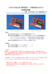
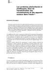
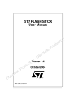
1
Service Manual
Model
VR800
VR800Z
Digital Multitrack Recorder
CAUTION:
CAUTION
TO PREVENT ELECTRIC SHOCK, MATCH
RISK OF ELECTRIC SHOCK
DO NOT OPEN
WIDE BLADE OF PLUG TO WIDE SLOT,
FULLY INSERT.
CAUTION: TO REDUCE THE RISK OF ELECTRIC SHOCK,
ATTENTION:
POUR ÉVITER LES CHOCS ÉLECTRIQUES,
DO NOT REMOVE COVER (OR BACK).
INTRODUIRE LA LAME LA PLUS LARGE DE
NO USER-SERVICEABLE PARTS INSIDE.
L A F I C H E D A N S L A B O R N E C O RR E-
REFER SERVICING TO QUALIFIED SERVICE PERSONNEL.
SPONDANTE DE LA PRISE ET POUSSER
JUSQU' AU FOND.
The lightening flash with arrowhead symbol,
within an equilateral triangle, is intended to
alert the user to the presence of uninsulated
“dangerous voltage” within the product's enclosure that may be of sufficient magnitude to
constitute a risk of electric shock to persons.
The exclamation point within an equilateral
triangle is intended to alert the user to the
presence of important operating and maintenance (servicing) instructions in the literature
accompanying the appliance.
“WARNING”
“TO REDUCE THE RISK OF FIRE OR ELECTRIC SHOCK, DO
NOT EXPOSE THIS APPLIANCE TO RAIN OR MOISTURE.”
SAFETY INSTRUCTIONS
1.
2.
3.
4.
5.
6.
Read instructions - All the safety and operating instructions
should be read before the appliance is operated.
Retain instructions - The safety and operating instructions
should be retained for future reference.
Heed warnings - All warnings on the appliance and in the operating instructions should be adhered to.
Follow instructions - All operating and use instructions should
be followed.
Water and Moisture - The appliance should not be used near
water - for example, near a bathtub, washbowl, kitchen sink,
laundry tub, in a wet basement, or near a swimming pool, and
the like.
Carts and Stands - The appliance should be used only with a
cart or stand that is recommended by the manufacturer.
9.
10.
11.
12.
13.
14.
15.
16.
7.
8.
An appliance and cart combination should be moved with
care. Quick stops, excessive force, and uneven surfaces
may cause the appliance and cart combination to overturn.
Wall or Ceiling Mounting - The appliance should be mounted to
a wall or ceiling only as recommended by the manufacturer.
Ventilation - The appliance should be situated so that its location or position does not interfere with its proper ventilation. For example, the appliance should not be situated on a
bed, sofa, rug, or similar surface that may block the ventilation openings; or, placed in a built-in installation, such as a
bookcase or cabinet that may impede the flow of air through
the ventilation openings.
17
Heat - The appliance should be situated away from heat
sources such as radiators, heat registers, stoves, or other appliances (including amplifiers) that produce heat.
Power Sources - The appliance should be connected to a
power supply only of the type described in the operating instructions or as marked on the appliance.
Grounding or Polarization - The precautions that should be
taken so that the grounding or polarization means of an appliance is not defeated.
Power Cord Protection - Power supply cords should be routed
so that they are not likely to be walked on or pinched by items
placed upon or against them, paying particular attention to
cords at plugs, convenience receptacles, and the point where
they exit from the appliance.
Cleaning - The appliance should be cleaned only as recommended by the manufacturer.
Nonuse Periods - The power cord of the appliance should be
unplugged from the outlet when left unused for a long period of
time.
Object and Liquid Entry - Care should be taken so that objects
do not fall and liquids are not spilled into the enclosure through
openings.
Damage requiring Service - The appliance should be serviced
by qualified service personnel when:
A.
The power supply cord or the plug has been damaged;
or
B.
Objects have fallen, or liquid has been spilled into the
appliance; or
C. The appliance has been exposed to rain; or
D. The appliance does not appear to operate normally or
exhibits a marked changed in performance; or
E.
The appliance has been dropped, or the enclosure damaged.
Servicing - The user should not attempt to service the appliance beyond that described in the operating instructions. All
other servicing should be referred to qualified service personnel.
VR800 / VR800Z
TABLE OF CONTENTS
1.
2.
3.
4.
5.
6.
7.
8.
SPECIFICATIONS ..................................................................................... 4
CONTROLS, INDICATORS AND CONNECTORS ............................. 6
SOFTWARE UPDATE ............................................................................. 8
SERVICE MODE ...................................................................................... 9
ERROR CODE LIST .............................................................................. 19
INSTALLING INTERNAL DRIVE....................................................... 20
EXPLODED VIEW, PCB ASSEMBLY AND PARTS LIST............ 22
CIRCUIT DIAGRAMS ........................................................................... 35
NOTES
* Service mode, error code list, exploded view, PCB assembly, parts list and circuit diagrams are given in
this manual to assist the service technician in maintaining the Model VR800.
* The following accessories are supplied with VR800/VR800Z as the standard accessories.
Owner's manual, VR800
: 8288429000 (for export model)
: 8288430000 (for domestic model)
Quick manual, VR800
: 8288442000 (for export model)
: 8288443000 (for domestic model)
Manual, supplement, VR800Z : 8288667000
Manual, supplement, Screw
: 8288668000
* Following is the packing material for the Model VR800.
CARTON, INNER, VR800
: 8228726000
PACKING, SIDE, L, VR800 : 8228450000
PACKING, SIDE, R, VR800 : 8228451000
CAUTION :
Parts marked with this sign are safety critical components. They must always be replaced with
identical components. Refer to the Fostex Parts List and ensure exact replacement.
3
VR800 / VR800Z
1. SPECIFICATIONS
INPUT & OUTPUT
DATA IN
Connector
Format
DATA OUT
Connector
Format
MIDI IN
Connector
Format
MIDI OUT
Connector
Format
PUNCH IN / OUT
Connector
WORD OUT
Connector
SCSI
Connector
Protocol
Transfer type
Number of device to be connected
SCSI ID: 0 ~ 5
SCSI ID: 6
Square shape optical
IEC consumer optical standard IEC 60958(S/P DIF)
ALESIS Proprietary Multi Channel Optical Digital Interface
Square shape optical
IEC consumer optical standard IEC 60958(S/P DIF)
ALESIS Proprietary Multi Channel Optical Digital Interface
DIN 5-pin
Comply to MIDI standard
DIN 5-pin
Comply to MIDI standard
φ6 mm phone jack (CMOS level)
BNC (TTL level)
D-SUB 25-pin
SCSI-2, unbalanced transfer method
Asynchronous
2
Recording / reproducing
Data backup
RECORD & REPRODUCE
Recording Medium
Standard
Sampling Frequency
Quantization
Emphasis
Compression / Expansion Method
Recording Time (mono track min.)
MASTERING mode
NORMAL mode
Number of Tracks
Number of recording tracks
Number of simultaneous recording tracks
Number of simultaneous playback tracks
4
Internal 3.5” E-IDE hard disk drive (VR800)
Internal ATAPI zip drive (VR800Z)
External fixed / removable hard disk drive (optional)
SCSI-2 or better
44.1 kHz
16-bit linear
Not available
A.D.A.C. (Advanced Digital Audio Acoustic Coding)
About 18 min. / 100 MB at maximum
About 72 min. / 100 MB at maximum
Recording time will be limited up to 24 hours.
24 tracks (8 + 16 additional tracks)
8 (Depending on characteristics of recording medium)
8 (Depending on characteristics of recording medium)
8 (Depending on characteristics of recording medium)
VR800 / VR800Z
RECORD & REPRODUCE (Continued)
Recording Format
Recording Mode
Pitch Control
Crossfade
FDMS-3
NORMAL mode (A.D.A.C., 8 + 16 tracks, default)
MASTERING mode (linear recording, 8 + 16 tracks)
±6.0 %
10 msec
OPERATION
FFWD/REW Speed
Shuttle Speed (SHIFT + JOG)
Digital Scrubbing (JOG)
Locate Memory
±3, 32 times
±1, 2, 4, 8, 16, 32, 64 times
0 ~ 1 times (Envelope can be displayed when selecting only one track.)
6 (7 including [LOCATE] key temporary memory) + 99
LEVEL INDICATION
Type
Number of Indicated Levels
Reference Level
LCD Bargraph
10 dots (-∞, -30, -24, -18, -12, -9, -6, -3, 0, OVER)
-12dB
GENERAL
Dimensions
Weight
Power Requirement
JPN
USA / CND
UK / EUR
Power Consumption
254 (W) x 285 (D) x 100 (H)
Approx. 2.0 kg
100V AC
120V AC
230V AC
15 W
*Specifications and appearance are subject to change without notice for product improvement.
5
VR800 / VR800Z
2. CONTROLS, INDICATORS AND CONNECTORS
< Top Panel Section >
2
3
4
OPTICAL
ACCESS
OL
0
6
12
24
1
2
3
4
5
6
7
8
A SYNC
1
RECORD TRACK
30
29
28
27
1
2
START
6
7
8
IN
OUT
EXIT
/ NO
EXECUTE
/ YES
UNDO / REDO
DISP SEL
SETUP
LOCATE
TIME BASE SEL
SCRUB
3
4
5
IN
OUT
END
STORE
EDIT
VARI PITCH
AUTO RTN
AUTO PLAY
AUTO RTN
CLIPBOARD
AUTO PUNCH
PREVIEW
HOLD/
26
EJECT
PGM SEL
25
SHIFT
P.EDIT
RECORD
PLAY
JOG
SHUTTLE
11
LOC MEM
STOP
5
6
7
8
9
10
REW
F FWD
12
CLIPBOARD PLAY
LOCATE ABS 0
LOCATE REC END
AUTO
PUNCH
13
19
18
24
1.
2.
3.
4.
5.
6.
7.
8.
9.
10.
11.
12.
13.
14.
15.
6
17
23
16
22
15
21
Record track select keys [ RECORD TRACK (1 - 8) ]
Access LED [ ACCESS ]
LCD
Contrast adjustment knob
Clipboard In key [ CLIPBOARD IN / PREVIEW ]
Clipboard Out key [ CLIPBOARD OUT / PREVIEW ]
Exit/No key [ EXIT/NO / EJECT ]
Execute/Yes key [ EXECUTE / YES ]
Display indication select key [ DISP SEL ]
Setup key [ SETUP ]
Undo/Redo key [ UNDO / REDO ]
Edit key [ EDIT ]
JOG dial [ JOG / SHUTTLE ]
Scrub key [ SCRUB ]
Time Base select key [ TIME BASE SEL ]
14
20
16.
17.
18.
19.
20.
21.
22.
23.
24.
25.
26.
27.
28.
29.
30.
Locate key [ LOCATE / LOC MEM ]
Auto Return/Auto Play mode on/off key
Vari Pitch key [ VARI PITCH / P.EDIT ]
Shift key [ SHIFT ]
Fast forward button [ F FWD ]
Rewind button [ REWIND ]
Play button [ PLAY ]
Stop button [ STOP ]
Record button [ RECORD / AUTO PUNCH ]
Store key [ STORE ]
Hold/> key [ HOLD/> ]
Auto Return End key [ AUTO RTN END / PREVIEW ]
Auto Return Start key [AUTO RTN START / PREVIEW]
Auto Punch In key [ AUTO PUNCH IN / PREVIEW ]
Auto Punch Out key [AUTO PUNCH OUT / PREVIEW]
VR800 / VR800Z
< Rear Panel Section > 31
WORD OUT
SCSI
OPTICAL
32 33
34
DATA
OUT
IN
OUT
35
MIDI
IN
36
31.
32.
33.
34.
AC IN
37
SCSI connector [SCSI] (Connector: D-SUB 25-pin)
Data output jack [DATA OUT] (Connector: OPTICAL)
Data input jack [DATA IN] (Connector: OPTICAL)
MIDI OUT jack [MIDI OUT] (Connector: DIN 5-pin)
35.
36.
37.
38.
POWER
38
MIDI IN jack [MIDI IN] (Connector: DIN 5-pin)
Word Out jack [WORD OUT] (Connector: BNC)
AC IN connector
Power switch [POWER]
< Side Panel Section - VR800 >
40
39
PUNCH
IN/OUT
40
< Side Panel Section - VR800Z >
39
PUNCH
IN/OUT
39. Blannk Panel (VR800)
Zip Drive (VR800Z)
40. Punch in/out jack [PUNCH IN/OUT]
(Connector: phone)
7
VR800 / VR800Z
3. SOFTWARE UPDATE
The VR800 software can be updated through the SCSI port. This means that unscrewing and opening up the VR800 panel is not
necessary to change the EPROMs. Please refer to the following explanation for correct software updating procedures.
3-1. Method of Sending Software from Fostex Japan
There are two ways of sending the VR800 updated software.
1. Updated software in a removable medium (e.g. floppy disk, zip disk, etc.) to be sent via airmail
2. Updated software as an attachment file to be sent via E-mail
3-2. Required Tools
The following tools/equipment are required to update the VR800 software.
1. IBM PC/AT compatible computer with SCSI board
2. Removable type SCSI drive
3. Cable between the removable type SCSI drive and the SCSI board
4. Cable between the removable type SCSI drive and the VR800 (D-SUB 25-pin)
3-3. Software Updating Procedures
Presuming that the updated software is correctly sent and is copied into your computer.
1. Connect the removable type SCSI drive to the IBM PC/AT compatible computer SCSI port.
2. Insert the diskette to the removable type SCSI drive and format it by the computer on which Windows 95/98 is running.
3. Copy the updated software file to the removable type SCSI drive (diskette).
4. Set the removable type SCSI drive ID to 0 ~ 5 and connect to the VR800 SCSI port.
5. Turn on the power of removable drive and then VR800. The VR800 LCD display shows “No Disk”.
6. Insert the diskette with updated software file. The VR800 LCD display shows “No Disk”, “Initial..”, “name of drive
(e.g. ZIP 100)” and “updated software file name” in order and comes to a standstill at the display below. Memorize the
displayed ROM version and date before updating the software.
: blinking
?
7. Pressing the [EXECUTE/YES] key would start updating the software. The display shows “Loading!”, “Writing!” and
“Initial..” in order and automatically returns to the above condition again. Check the displayed ROM version and date
if the software is correctly updated by the optional mode “4-2. Flash ROM & CPU Version” (page 10).
8. Eject the diskette with updated software file by the press of [STOP] button or [EXIT/NO] key and insert the diskette
formatted by the VR800.
CAUTION:
1. The diskette in which the updated software file is copied must be formatted by IBM PC/AT computer, not by Macintosh.
2. If something wrong happens while updating the software (e.g. A blackout occurred while updating the software.), the
VR800 might not be able to boot up the system software inside the Flash ROM. In such a case, please refer to the
section “4-8. Flash ROM” (page 17).
3. The SCSI ID to be connected to the VR800 must be selected to 0 ~ 5. The SCSI ID “6” is used for backing up purpose
exclusively. The SCSI ID “7” cannot be used by technical reasons.
8
VR800 / VR800Z
4. SERVICE MODE
There are various optional modes available in the VR800 Service Mode. Please utilize them when servicing the unit.
4-1. Putting VR800 into Service Mode
The way of putting the VR800 into Service Mode is as follow.
1. Connect a SCSI device, insert the diskette formatted by the VR800 and turn the power of SCSI device on.
2. After confirming that the access LED on the SCSI device is lit and then goes out, turn on the power of VR800.
3. While holding down the [STOP] button and [SHIFT] key, press the [SETUP] key.
As shown below, by rotating the jog dial C.W. or C.C.W., various optional modes will be displayed in addition
to the general SETUP menus. In order to select a certain optional mode, press the [EXECUTE/YES] key while
its menu is displayed.
Sign.Set? TempoSet?
TitleEdit? Del_PGM?
Preroll?
Click_ ?
SyncOut?
C.W.
N/A
Version?
N/A
N/A
DA_Test?
FrameRate?
Disp.Test?
MtcOffset?
C.W.
N/A
C.W.
SelfCheck?
C.W.
N/A
N/A
OfsetMode?
C.W.
OfsetDisp?
SlaveMode?
C.W.
C.W.
N/A
BkFormat?
Format?
Test_1?
SlaveType?
Freeblock? FlashROM? Init.Disk?
RecProtect?
C.W.
Save_PGM? Load_PGM? NOsEvent? DeviceID?
Format?
Resolu?
Digi.out?
Digi.In?
: SETUP Mode menu
: Service Mode menu
N/A : Not Available
VR800 LCD Display Section
9
VR800 / VR800Z
4-2. Flash ROM & CPU version
: blinking
This mode is used to check the Flash ROM and CPU versions
currently installed in the unit.
In order to check the version number, press the [EXECUTE/
YES] key while “?” is blinking as shown in the left.
: blinking
The example on the left indicates that the Flash ROM version
is V1.01 and its programming date is April 13, 1999.
In this condition, by turning the jog dial C.W. or C.C. W.,
the CPU version can be checked.
: blinking
The example on the left indicates that the CPU version is
V2.00 and its programming date is August 4, 1998.
4-3. DA Test
: blinking
10
Since there are no A to D and D to A converters used on the
VR800. this service mode does not function.
VR800 / VR800Z
4-4. Display/Button Test
: blinking
This mode tests if all the segments on the LCD display, LEDs
and buttons (switches) on the VR800 top panel are correctly
working or not.
To execute this test, press the [EXECUTE/YES] key while
“?” is blinking.
If the VR800 is in a normal condition, all the segments on
the LCD display will be lit solid and all the LEDs on the top
panel will start blinking.
?
If the VR800 is not in a normal condition, faulty segments
on the LCD display and/or LEDs on the top panel will remain
unlit.
In this condition, if the [EXECUTE/YES] key is pressed one
more time, the Button Test can be executed.
The Button Test checks if each key/button and jog dial are
working properly or not. The display on the left indicates
that the [RECORD] button is pressed and held down. (“K”
stands for the Key and “J” the Jog dial.)
The display on the left indicates the condition when the jog
dial is turned C.W.
The table below shows the relationship between the key/
button/jog dial and the corresponding numbers appear on the
LCD display.
In order to quit the Button Test, turn the jog dial C.W. or C.C.W.
further after “J_20” or “J-19” is displayed respectively.
Key/Button/Jog Dial
RECORD
STOP
PLAY
REWIND
F FWD
SHIFT
VARI PITCH / P.EDIT
AUTO RTN / PLAY
LOCATE / LOC MEM
TIME BASE SEL
SCRUB
HOLD
No.
K01
K02
K03
K04
K05
K06
K07
K08
K09
K10
K11
K12
Key/Button/Jog Dial
STORE
EDIT
UNDO / REDO
DISP SEL
SETUP
AUTO RTN START
AUTO PUNCH IN
AUTO PUNCH OUT
AUTO RTN END
CLIPBOARD IN
CLIPBOARD OUT
EXIT / NO / EJECT
No.
K13
K14
K15
K16
K17
K18
K19
K20
K21
K22
K23
K24
Key/Button/Jog Dial
EXECUTE / YES
RECORD TRACK 1
RECORD TRACK 2
RECORD TRACK 3
RECORD TRACK 4
RECORD TRACK 5
RECORD TRACK 6
RECORD TRACK 7
RECORD TRACK 8
JOG DIAL (C.W.)
JOG DIAL (C.C.W.)
No.
K25
K26
K27
K28
K29
K30
K31
K32
K33
J 00 ~ 20
J -00 ~ -19
11
VR800 / VR800Z
4-5. Self Check
This mode automatically tests the following points in order.
• SCSI port
• ATA (E-IDE) bus
• MIDI in/out circuit
• S/P DIF digital signal (44.1kHz)
• adat digital signal (44.1kHz)
• Vari-pitch circuit
○○ ○ ○ ○ ○ ○ ○ ○ ○ ○ ○ ○ ○
<Cable Connection in “ Self Check ” Mode>
WORD OUT
SCSI
OPTICAL
DATA
OUT
IN
External SCSI Device Optical cable
MIDI
OUT
IN
MIDI cable
AC IN
POWER
○ ○ ○ ○ ○ ○ ○ ○ ○ ○ ○ ○ ○ ○ ○ ○ ○ ○ ○ ○ ○ ○ ○ ○ ○ ○
CAUTION :
In order not to form a MIDI signal loop,
connect the MIDI cable after putting the
VR800 into the Service Mode.
○ ○ ○ ○ ○ ○ ○ ○ ○ ○ ○ ○ ○ ○
: blinking
○ ○ ○ ○ ○ ○ ○ ○ ○ ○ ○ ○ ○ ○ ○ ○ ○ ○ ○ ○ ○ ○ ○ ○ ○ ○ ○ ○ ○ ○ ○ ○ ○ ○ ○ ○ ○ ○ ○ ○ ○ ○ ○ ○ ○ ○ ○ ○ ○ ○ ○ ○
To start the Self Check mode, press the [EXECUTE/YES] key
when “?” is blinking.
The VR800 automatically checks the before mentioned points.
If the VR800 is working properly, the following appears on the
display with REC LED blinking.
In order to go back to the normal display, press the [EXIT/NO]
key or [STOP] button.
Fs, DIGITAL IN, DIGITAL OUT and SLAVE MODE settings on the disk to be used when the Self Check test is executed
should be as follow.
• Fs
: 44.1kHz
• DIGITAL IN
: OFF (L: - R: -)
• DIGITAL OUT : ADAT
• SLAVE MODE : OFF
12
VR800 / VR800Z
4-5-1. SCSI Port Check
If the VR800 does not recognize a SCSI device connected to the
VR800 SCSI port, the prompt below will be displayed.
The following is considered to be the cause of problem.
• Bad cable connection, bad cable contact and / or the power
of SCSI device is being turned off.
• SCSI device ID is not set to 0 ~ 5.
• MAIN PCB is defective. (bad soldering of U7, U8, J6, etc.)
If a removable type SCSI drive is connected and in case a disk is
not inserted into the drive, the following prompt will be displayed.
In the case that the inserted disk is not FDMS-3 formatted, the
following prompt will be displayed.
Even if the before mentioned prompt is displayed, pressing the [EXECUTE/YES] key would reach the next test.
4-5-2. ATA (E-IDE) Bus Check
This test checks if data can be properly read out from the
preformatted internal drive.
If the data (SYSTEM ID) written by formatting the disk cannot
be read out correctly, the Self Check mode comes to a standstill
at “AtaBusChk (check)” test.
The following is considered to be the cause of problem.
• The internal drive is not installed in the VR800.
• Breaking, shortage and / or bad contact of flat cable J12.
• Bad soldering of gate array U5 on the MAIN PCB.
Even if the before mentioned prompt is displayed, pressing the [EXECUTE/YES] key would reach the next test.
13
VR800 / VR800Z
4-5-3. MIDI In/Out Check
By connecting the MIDI IN and OUT ports, this test checks if
the reply against the ID inquiry is correctly received. If not, the
prompt below will be displayed.
The following is considered to be the cause of problem.
• Bad soldering of J2, U11 and surrounding circuit on the
MAIN PCB
Even if the before mentioned prompt is displayed, pressing the [EXECUTE/YES] key would reach the next test.
4-5-4. S/P DIF In/Out Check
By connecting the DATA IN and OUT terminals, this tests checks
if the S/P DIF signal output by itself is correctly received. If the
PLL circuit is not in a “LOCKED” condition, the prompt below
will be displayed.
The following is considered to be the cause of problem.
• Defect on DIGITAL OUT
- No oscillation of resonator X1.
- Connector J4, gate array U5, U20 and / or surrounding
circuit are defective.
• Defect on DIGITAL IN
- Connector J5, gate array U5, U20 and / or surrounding
circuit are defective.
- PLL circuit (U10 and surrounding circuit) are defective.
• The SETUP “DIGITAL IN” is set other than “L: - R: -”.
Even if the before mentioned prompt is displayed, pressing the [EXECUTE/YES] key would reach the next test.
14
VR800 / VR800Z
4-5-5. Adat In/Out Check
By connecting the DATA IN and OUT terminals, this tests
checks if the ADAT digital signal output by itself is correctly
received. If the PLL circuit is not in a “LOCKED” condition,
the prompt below will be displayed.
The following is considered to be the cause of problem.
• Defect on DIGITAL OUT
- No oscillation of resonator X1.
- Connector J4, gate array U5, U20 and / or surrounding
circuit are defective.
• Defect on DIGITAL IN
- Connector J5, gate array U5, U20 and / or surrounding
circuit are defective.
- PLL circuit (U22, 23, 35, 36, 37, 38, 39 and / or
surrounding circuit) are defective.
• The SETUP “DIGITAL IN” is set other than “L: - R: -”.
Even if the before mentioned prompt is displayed, pressing the [EXECUTE/YES] key would reach the next test.
4-5-6. Vari-Pitch Circuit Check
Using the master clock generated through the VR800 vari-pitch
circuit on the MAIN PCB, the adat digital signal is output. This
test checks if the adat digital signal output by itself is correctly
received. If not, it means that the vari-pitch circuit does not work
correctly. As a result, the prompt below will be displayed.
The following is considered to be the cause of problem.
• Defects on the vari-pitch circuit (U3, U9), gate array (U5)
and / or surrounding circuit.
Even if the before mentioned prompt is displayed, pressing the [EXECUTE/YES] key would reach the next test.
15
VR800 / VR800Z
4-6. Offset Display
: blinking
This mode determines if the offset value against a master machine
should be displayed when the VR800 is working as a slave
machine. If you would like to turn “ON” the offset display, press
the [EXECUTE/YES] key while “?” is blinking. (The default
setting is “off”.) Then, turn the jog dial C.W. to change the setting
to “ON” and press the [EXECUTE/YES] key.
In order to check the offset value, select the “MTC” time base
and the “REMAINING TIME” display. The display below is an
example of offset display.
CAUTION:
There might be a case that the percentage value does not indicate
“0.0%” exactly. This is caused by the difference of internal clocks
between master and slave machines, which are running
independently.
4-7. Initializing Disk
: blinking
?
CAUTION:
1. If both the external SCSI drive and the internal drive are
connected at the same time, the current drive will be initialized.
2. Up to 2 x SCSI drives can be connected to the VR800 at a
time. One is for recording / reproducing (SCSI ID: 0 ~ 5) and
the other for exclusive backing up (SCSI ID: 6). Initializing
is possible on the SCSI drive (ID: 0 ~ 5) used for recording /
reproducing only.
: blinking
?
16
This mode initializes an external SCSI device connected to the
SCSI port or an internally installed drive. The disk drive currently
connected can be initialized.
After pressing the [EXECUTE/YES] key, “SURE?” will start
blinking in the FL display. In this condition, pressing the
[EXECUTE/YES] key one more time would initialize the
recognized disk drive. This mode puts the disk back to the
condition originally formatted.
VR800 / VR800Z
4-8. Flash ROM
: blinking
This mode is used when copying the system software from ROM
CARD PCB assy (P/N : 8274219000) to Flash ROM. As
mentioned in the section “3. SOFTWARE UPDATE” (page 8),
the VR800 software inside the Flash ROM can be updated through
the SCSI port. However, if something wrong happens when
updating the software (e.g. A blackout occurred while updating
the software.), the VR800 might not be able to boot up by the
system software inside the Flash ROM.
In this case, the following procedures must be taken.
1. Turn off the power of VR800 and turn the switch on the ROM CARD PCB assy to “EPROM” side.
2. Plug the EPROMs into the sockets on the ROM CARD PCB assy which will be supplied to you separately.
3. Connect the ROM CARD PCB assy to J10 (50-pin connector) on the MAIN PCB assy.
4. Turn on the power of VR800.
In this condition, the VR800 is booted up by the system software inside the EPROMs. The next procedures to take are as follows.
1. Put the VR800 into the Service Mode, select “FlashROM” and press [EXECUTE/YES] key. (“SURE?” is blinking.)
2. Press the [EXECUTE/YES] key one more time to copy the system software from EPROMs to Flash ROM.
3. After the completion, turn the switch on the ROM CARD PCB assy to “FLMEM” side.
4. In order to confirm that the VR800 is correctly booted up using the system software inside the Flash ROM, turn off the
power, disconnect the cable connected to the J10 on the MAIN PCB assy and turn the power back on again.
5. After the confirmation, referring to the section “3. SOFTWARE UPDATE” (page 8), update the system software
inside the Flash ROM through SCSI port again.
17
VR800 / VR800Z
4-9. Free Block Check
: blinking
This mode is used to check the condition of the diskette inserted
into an external SCSI drive connected to the VR800 or the
internal drive. (As mentioned before, the SCSI drive has a
priority unless the SCSI ID is set to “6”.)
Press the [EXECUTE/YES] key when “?” is blinking. The display
indicates the free audio file numbers.
If the Free Block indicates a large number even after formatting
and no signal is recorded or recorded signals are frequently
skipped, the diskette / hard disk drive can be judged to be in a
bad condition.
4-11. Test 1
: blinking
18
This Service Mode is exclusively designed for software
programming purpose. There is nothing to do with servicing /
repairing the VR800.
VR800 / VR800Z
5. ERROR CODE LIST
The chart below indicates the error code number and corresponding description. Since the error code list is basically
designed for our engineers to improve the software, the description is quite technical. If you find the VR800 with one of the
error codes displayed, we encourage you to update the software first. In case updating the software does not solve the
problem, we would like you to inform us about details.
ERROR CODE LIST
ERROR
CODE
DESCRIPTION
1
The FD-8 tries to access the address which does not exist.
3
SCSI drive does not boot up correctly when in SCSI access operation.
9
When saving system region sector, its address is registered in Free_block File during Free block File checking procedure.
10
Link_pointer which links Audio File indicates smaller address (out of region) than Link_File address region in RAM.
11
Link_pointer indicates larger address (out of region) than Link_File address region in RAM.
12
"Pointer_addre" calculation of Link_Pointer is not correct.
14
Link_Pointer during recording/reproducing indicates smaller address (out of region) than actual Link_File address region.
15
Link_Pointer during recording/reproducing indicates larger address (out of region) than actual Link_File address region.
16
"Pointer_addre" calculation of Link_Pointer during recording/reproducing is not correct.
20
src_cash_load: Improper access of link address occurred while PASTE editing.
21
bak_cash_load: Program link during PASTE/MOVE editing is incorrect.
22
bak_cash_load: Imcompatibility problem occurred on program link during PASTE/MOVE editing.
30
Error when executing MOVE editing. Improper Link Pointer. Error in "bak_cash_load" function.
31
Error when executing MOVE editing. Improper Link Pointer. Error in "bak_cash_load" function.
32
Error when executing MOVE editing. Improper Link Pointer. Error in "bak_cash_load" function.
35
Backup_Save:Error occurred when saving data to SCSI device.
36
Backup_Load: Error occurred when loading data from SCSI device.
38
Displayed in Test Mode only. SCSI device cannot be recognized during initial test.
40
dis_cah_load: Improper access occurred when recording/reproducing.
41
dis_cah_load: Improper access occurred when recording/reproducing.
42
dis_cah_load: Improper access occurred when recording/reproducing.
45
get_non_des_block: Remaining disk capacity is insufficient.
52
non_des_cash_save_sub: Improper access occurred when recording/reproducing.
60
remake_free_block: There was improper access to program management region.
61
remake_free_block: There was improper access to program management region.
62
remake_free_block: Number of manageable events exceeds limit.
63
remake_free_block: There was improper access to program management region.
64
remake_free_block: There is an overlapping section in program management region.
96
There was improper access to program management region.
97
There was improper access to program management region when saving System File.
99
There was improper access when fading in/out.
19
VR800 / VR800Z
6. INSTALLING INTERNAL DRIVE
The 3.5” internal drive(E-IDE hard disk drive or ATAPI zip drive) installing procedures are explained below.
1)
Using 4 x inch screws, fix the bracket (P/N : 8221277000 : Blacket, RHD, VR800) to a 3.5" E-IDE HDD.
Bottom
side
40-pin
When installing the ATAPI zip drive (P/N: 8270587000)
supplied from Fostex as a VR800 service part, fix it using the
hole on the bracket indicated below, so that the VR800Z side
panel would be even with the zip drive disk insertion surface.
4-pin
ide
Front s
e
zip driv
Bottom
side
CAUTION :
• The internal drive must be set to “MASTER”.
• There are 4x inch screws and 8x metric screws are included in the VR800 as well as the VR800Z. When fixing the HDD
to the bracket, use the inch screws. On the other hand, use the metric screws when fixing the zip drive to the bracket.
2) Loosen 6 x screws (BBT 3 x 8 BZn) fixing the bottom panel of the VR800.
Two cables used to connect to the internal disk appear when you remove the bottom panel.
J12
40-pin flat cable
CAUTION :
When installing the ATAPI zip drive, remove
the side panel prior to the installation.
20
W1
4-pin cable
VR800 / VR800Z
3) Using 4 x screws (B 3 x 5 BZn), fix the internal drive/bracket to the VR-800.
Adjust the tightening position of screws to the internal drive/bracket and to the VR-800 so that screws are not
bothered from each other.
4) Connect the J12 (40-pin flat cable) and W1 (4-pin cable) from the MAIN PCB assy to the internal drive connectors
In order to connect pins straight, twist the cable as shown below.
J12
W1
4) Tighten 6 x screws (BBT 3 x 8 BZn) fixing the bottom panel of the VR800.
21
22
1
15
11
12
3
2
5
BBT 3x8 CZn
13 14
BBT 3x8
Czn
BBT 3x8
CZn
A
9
13
14
6
4
8
30
10 29
7
16
BBT 3x8 BZn
BBT 3x8
BZn
25
26
B 3x8
BZn
BBT 3x8 BZn
SEMS 4x8
CZn
A
17
BBT 3x8
BZn
28
27
24
23
19
20
21
22
BBT 3x8 BZn
B 3x6
CZn
BBT
3x8
CZn
18
VR800 / VR800Z
7. EXPLODED VIEW, PCB ASSEMBLY AND PARTS LIST
• EXPLODED VIEW
VR800 / VR800Z
• EXPLODED VIEW Parts List
Ref. No.
1
2
3
4
5
6
7
8
9
10
11
12
13
14
15
16
17
18
19
20
21
22
23
24
25
26
27
28
29
30
Part No.
8212656100
8226238000
8216704000
8212657000
8274200000
8221274000
8274197000
8276839615
8270857000
8221277000
8226250002
8226250001
8226246001
8226246002
8274199000
8221271000
8226013003
8274203000
8216668000
8221278000
8245340000
8245166000
8277446010
8276800000
8276801000
8276802100
8276917000
8221261000
8274198000
8274196000
8221272000
8221273000
8207012000
Description
PANEL, TOP, VR-800
KNOB, JOG, FD-4
SHEET, JOG, VR800
WINDOW, LCD, VR800
PCB_ASSY, JOG, VR800
PANEL, BLANK, VR800
PCB_ASSY, LCD, VR800
CABLE, FLAT, FFC, 17P, L150
ZIP_100, ATAPI
BRACKET, RHD, VR800
BUTTON, 10X10, RED
BUTTON, 10X10, LED
BUTTON, 7X13, LED
BUTTON, 7X13, N4.5
PCB_ASSY, KEY, VR800
CHASSIS, VR800
BUTTON, PUSH, B, N
PCB_ASSY, FOOT_SW, VR800
SHIELD, PHONE, FD-4
BRACKET, PUNCH, VR800
NUT, PHONEJACK
CONN, WI, JACK, BNC, 01K0312
CABLE_ASSY, 1P, SMF/F-KINK, L10
CORD, POWER, DM, VM1292-1298
CORD, POWER, UL/CSA, VM0033-0089
CORD, POWER, CEE, 0309B-0310B
CORD, POWER, BS, 3C, KP610-KS31A
BRACKET, AC-IN, D-108
PCB_ASSY, ADAC, VR800
PCB_ASSY, MAIN, VR800
PANEL, BOTTOM, VR800
PANEL, RHD, VR800
FOOT, FF-822
23
VR800 / VR800Z
• MAIN PCB ASSY Parts List
Ref. No.
B101
24
Part No.
Description
8274196000 PCB_ASSY, MAIN, VR800
8251981101 PLAIN PCB, MAIN
Ref. No.
Part No.
U004
U005
U006
U007
U008
U009, 010
U011
U012
U013
U014
U015
8236545000
8236081800
8236561004
8236082800
8236082900
8236503400
8234504700
8236545014
8236502500
8236570101
8236083802
U016
U020
U022
U023
U024
U029
U030
U033
8236545139
8236085000
8236503400
8236545074
8236545032
8236545157
8236084011
8236083120
U035
U036
U037, 038
U039
U040
U041
U042
U101
U102
U103
U104
U105
8236545086
8236560161
8236545074
8236545074
8236570401
8236570101
8236560004
8236541006
8234108100
8236540900
8236085900
8236541300
Ref. No.
Part No.
D001
D003~007
D101
D102
D103
D104
D105, 106
8234105000
8234502800
8234107700
8234107900
8234505200
8234108000
8234108400
ICs
Description
ST, TSSOP, 74VHC00
QFP, DG, GATEARRAY, ASPI
ST, DG, 74HCU04
QFP, DG, SCSI, MB86604L
SOP, DG, SCSITERM, BH9595FP-Y
ST, DG, VCO, TC9246F
OPT, T, PHOTO, PC410T
ST, TSSOP, 74VHC14
ST, AN, RESET, NJM2103M
ST, DG, DRIVER, DTC114EK
QFP, DG, CPU, MAIN, FD-8, MASK,
SH7042, F28
ST, TSSOP, 74VHC139
QFP, DG, GATEARRAY, DIF
ST, DG, VCO, TC9246F
ST, TSSOP, 74VHC74
ST, TSSOP, 74VHC32
ST, TSSOP, 74VHC157
TSOP, DG, FROM, M29F400T-400, SGS
SOJ, DG, DRAM, TMS418160A-60A60DZ
ST, TSSOP, 74VHC86
ST, DG, 74HC161A
ST, TSSOP, 74VHC74
ST, TSSOP, 74VHC74
ST, DG, DRIVER, DTA114EK
ST, DG, DRIVER, DTC114EK
ST, DG, 74HC04
V, AN, POWER, MIP166
OPT, H, PHOTOCOUPLER, ON3171
VT, AN, REGULATOR, AN1431T
V, AN, DC-DC, PQ1CF1
ST, AN, DC-DC, NJM2360AM
DIODEs
Description
D, VF, SCHOTTKY, EK13
D, ST, DAN202K
D, STACK, 600VAC, 1.5A, D2SBA60
D, HT, 80V, 0.2A, MA171
D, V, 600V, 1.7A, S2V60-4002
D, V, 200V, 5.0A, MA649
D, VT, SCHOTTKEY, EK03W
Ref. No.
Part No.
R001~007
R008
R009
R010
R011
R012
R013
R014
R015
R016
R017
R019
R021~025
R026, 027
R029
R030
R031
R032
R033
R034
R035
R036
R038
R039
R040
R041
R042
R045
R047, 048
R049
R050
R051
R052~056
R059
R060
R061
R066
R068
R069
R070
R071
R073
R074
R076
R078
R079, 080
R084
R089, 090
R091
R093
R095, 096
R097
R099
R101
R102
8230500101
8230500103
8230500562
8230500332
8230500222
8230500101
8230500331
8230500105
8230500000
8230500101
8230500105
8230500472
8230500101
8230500000
8230500472
8230500152
8230500101
8230500224
8230500561
8230500471
8230500751
8230500822
8230500331
8230500103
8230500101
8230500561
8230500102
8230500103
8230500103
8230500331
8230500102
8230500103
8230500101
8230500331
8230500751
8230500472
8230500152
8230500331
8230500222
8230500331
8230500103
8230500000
8230500102
8230500101
8230500101
8230500103
8230500101
8230500103
8230500101
8230500473
8230500102
8230500105
8230500331
8230125104
8230500569
RESISTORs
Description
ST, CARBON, 1/10W, 100, 5%
ST, CARBON, 1/10W, 10K, 5%
ST, CARBON, 1/10W, 5.6K, 5%
ST, CARBON, 1/10W, 3.3K, 5%
ST, CARBON, 1/10W, 2.2K, 5%
ST, CARBON, 1/10W, 100, 5%
ST, CARBON, 1/10W, 330, 5%
ST, CARBON, 1/10W, 1M, 5%
ST, CARBON, 1/10W, 0, 5%
ST, CARBON, 1/10W, 100, 5%
ST, CARBON, 1/10W, 1M, 5%
ST, CARBON, 1/10W, 4.7K, 5%
ST, CARBON, 1/10W, 100, 5%
ST, CARBON, 1/10W, 0, 5%
ST, CARBON, 1/10W, 4.7K, 5%
ST, CARBON, 1/10W, 1.5K, 5%
ST, CARBON, 1/10W, 100, 5%
ST, CARBON, 1/10W, 220K, 5%
ST, CARBON, 1/10W, 560, 5%
ST, CARBON, 1/10W, 470, 5%
ST, CARBON, 1/10W, 750, 5%
ST, CARBON, 1/10W, 8.2K, 5%
ST, CARBON, 1/10W, 330, 5%
ST, CARBON, 1/10W, 10K, 5%
ST, CARBON, 1/10W, 100, 5%
ST, CARBON, 1/10W, 560, 5%
ST, CARBON, 1/10W, 1K, 5%
ST, CARBON, 1/10W, 10K, 5%
ST, CARBON, 1/10W, 10K, 5%
ST, CARBON, 1/10W, 330, 5%
ST, CARBON, 1/10W, 1K, 5%
ST, CARBON, 1/10W, 10K, 5%
ST, CARBON, 1/10W, 100, 5%
ST, CARBON, 1/10W, 330, 5%
ST, CARBON, 1/10W, 750, 5%
ST, CARBON, 1/10W, 4.7K, 5%
ST, CARBON, 1/10W, 1.5K, 5%
ST, CARBON, 1/10W, 330, 5%
ST, CARBON, 1/10W, 2.2K, 5%
ST, CARBON, 1/10W, 330, 5%
ST, CARBON, 1/10W, 10K, 5%
ST, CARBON, 1/10W, 0, 5%
ST, CARBON, 1/10W, 1K, 5%
ST, CARBON, 1/10W, 100, 5%
ST, CARBON, 1/10W, 100, 5%
ST, CARBON, 1/10W, 10K, 5%
ST, CARBON, 1/10W, 100, 5%
ST, CARBON, 1/10W, 10K, 5%
ST, CARBON, 1/10W, 100, 5%
ST, CARBON, 1/10W, 47K, 5%
ST, CARBON, 1/10W, 1K, 5%
ST, CARBON, 1/10W, 1M, 5%
ST, CARBON, 1/10W, 330, 5%
H, METAL, 2W, 100K, 5%, F20, RSS
ST, CARBON, 1/10W, 5.6, 5%
VR800 / VR800Z
Ref. No.
Part No.
R103
R104
R105
R106
R107
R108
R109
R110
R111
R112
R113
R114
R115
R913~915
R923
R924, 925
R926
R927
R928
R929
R930
8230500569
8230124330
8230500331
8230500393
8230500471
8230500103
8230500103
8230500302
8230500102
8230500472
8230500152
8234109500
8230500159
8230500221
8230500102
8230500103
8230500221
8230500332
8230503100
8230500102
8230500101
Ref. No.
C001
C002
C003, 004
C005, 006
C007
C008
C009
C010
C011, 012
C014
C015
C016
C019, 020
C021
C022~025
C026
C027
C028
C030
C031
C032
C033, 034
C037~040
C046
C047
C048
C049~051
C052
RESISTORs
Description
ST, CARBON, 1/10W, 5.6, 5%
HT, METAL, 1/2W, 33, 5%, RSS
ST, CARBON, 1/10W, 330, 5%
ST, CARBON, 1/10W, 39K, 5%
ST, CARBON, 1/10W, 470, 5%
ST, CARBON, 1/10W, 10K, 5%
ST, CARBON, 1/10W, 10K, 5%
ST, CARBON, 1/10W, 3K, 5%
ST, CARBON, 1/10W, 1K, 5%
ST, CARBON, 1/10W, 4.7K, 5%
ST, CARBON, 1/10W, 1.5K, 5%
D, V, THERMISTOR, NTH18D8ROL
ST, CARBON, 1/10W, 1.5, 5%
ST, CARBON, 1/10W, 220, 5%
ST, CARBON, 1/10W, 1K, 5%
ST, CARBON, 1/10W, 10K, 5%
ST, CARBON, 1/10W, 220, 5%
ST, CARBON, 1/10W, 3.3K, 5%
ST, CARBON1/2W, 10, 5%
ST, CARBON, 1/10W, 1K, 5%
ST, CARBON, 1/10W, 100, 5%
CAPACITORs
ALU = Electrolytic type
CER = Ceramic type
PES = Mylar type
Part No.
Description
8232352104
8232349103
8233502104
8232354222
8232353391
8233502104
8232324107
8232144476
8232357477
8233504103
8233500150
8233509474
8233504103
8232143106
8233504103
8232143106
8233500471
8233500101
8233500471
8233500220
8233500220
8233504103
8233504103
8232143106
8233502104
8232371187
8233504103
8233500150
PES, 250VAC, 0.1µF, 20%, ECQ-UMV
PES, 630V, 0.01µF, 10%, ECQ-EKF
CER, 50V, 0.1µF, +80, CC20F
CER, 250V, .0022µF, 20%, ECK-ZNS
CER, 500V, 390pF, 10%, ECK-ZHT
CER, 50V, 0.1µF, +80, CC20F
ALU, 400V, 100µF, 20%, SMH-VNSN, D2
ALU, 25V, 47µF, 20%, SME-VB
ALU, 16V, 470µF, 20%, LXV.D10
CER, 25V, 0.01µF, 10%, CC20R
CER, 50V, 15pF, 5%, CC20SL
CER, 25V, 0.47µF, 20%, KC30E
CER, 25V, 0.01µF, 10%, CC20R
ALU, 16V, 10µF, 20%, SME-VB
CER, 25V, 0.01µF, 10%, CC20R
ALU, 16V, 10µF, 20%, SME-VB
CER, 50V, 470pF, 5%, CC20SL
CER, 50V, 100pF, 5%, CC20SL
CER, 50V, 470pF, 5%, CC20SL
CER, 50V, 22pF, 5%, CC20SL
CER, 50V, 22pF, 5%, CC20SL
CER, 25V, 0.01µF, 10%, CC20R
CER, 25V, 0.01µF, 10%, CC20R
ALU, 16V, 10µF, 20%, SME-VB
CER, 50V, 0.1µF, +80, CC20F
ALU, 16V, 180µF, 20%, LXV, D6.3
CER, 25V, 0.01µF, 10%, CC20R
CER, 50V, 15pF, 5%, CC20SL
Ref. No.
C053~057
C058
C059
C060
C061, 062
C063
C064
C065
C066, 067
C068~070
C071
C072
C073
C074, 075
C076
C077
C078
C080
C081
C083~087
C088
C091
C093, 094
C095~099
C102, 103
C104
C106, 107
C108
C109, 110
C112
C114
C115
C116
C909
C911
C912
C919
C922
C923, 924
C925~929
C930
C931
C932
C933
C934
CAPACITORs
ALU = Electrolytic type
CER = Ceramic type
PES = Mylar type
Part No.
Description
8233504103
8233509474
8232371187
8233502104
8233504103
8232371187
8233500150
8233509474
8233504103
8233502104
8233504103
8232146105
8233504103
8233500330
8233504103
8233500101
8233500471
8232371187
8233502104
8233504103
8233502104
8232143106
8233504103
8233504103
8233502104
8232357477
8233502104
8232142107
8232354222
8232355477
8232143107
8232143107
8233500222
8233504103
8230500000
8233500330
8233500471
8233500470
8233500101
8233504103
8233500101
8233500471
8233502104
8233500471
8233504103
CER, 25V, 0.01µF, 10%, CC20R
CER, 25V, 0.47µF, 20%, KC30E
ALU, 16V, 180µF, 20%, LXV, D6.3
CER, 50V, 0.1µF, +80, CC20F
CER, 25V, 0.01µF, 10%, CC20R
ALU, 16V, 180µF, 20%, LXV, D6.3
CER, 50V, 15pF, 5%, CC20SL
CER, 25V, 0.47µF, 20%, KC30E
CER, 25V, 0.01µF, 10%, CC20R
CER, 50V, 0.1µF, +80, CC20F
CER, 25V, 0.01µF, 10%, CC20R
ALU, 50V, 1µF, 20%, SME-VB
CER, 25V, 0.01µF, 10%, CC20R
CER, 50V, 33pF, 5%, CC20SL
CER, 25V, 0.01µF, 10%, CC20R
CER, 50V, 100pF, 5%, CC20SL
CER, 50V, 470pF, 5%, CC20SL
ALU, 16V, 180µF, 20%, LXV, D6.3
CER, 50V, 0.1µF, +80, CC20F
CER, 25V, 0.01µF, 10%, CC20R
CER, 50V, 0.1µF, +80, CC20F
ALU, 16V, 10µF, 20%, SME-VB
CER, 25V, 0.01µF, 10%, CC20R
CER, 25V, 0.01µF, 10%, CC20R
CER, 50V, 0.1µF, +80, CC20F
ALU, 16V, 470µF, 20%, LXV.D10
CER, 50V, 0.1µF, +80, CC20F
ALU, 10V, 100µF, 20%, SME-VB
CER, 250V, .0022µF, 20%, ECK-ZNS
ALU, 6.3V, 470µF, 20%, LXV.D10
ALU, 16V, 100µF, 20%, SME-VB
ALU, 16V, 100µF, 20%, SME-VB
CER, 50V, .0022µF, 5%, CC20SL
CER, 25V, 0.01µF, 10%, CC20R
RES, ST, CARBON, 1/10W, 0, 5%
CER, 50V, 33pF, 5%, CC20SL
CER, 50V, 470pF, 5%, CC20SL
CER, 50V, 47pF, 5%, CC20SL
CER, 50V, 100pF, 5%, CC20SL
CER, 25V, 0.01µF, 10%, CC20R
CER, 50V, 100pF, 5%, CC20SL
CER, 50V, 470pF, 5%, CC20SL
CER, 50V, 0.1µF, +80, CC20F
CER, 50V, 470pF, 5%, CC20SL
CER, 25V, 0.01µF, 10%, CC20R
25
VR800 / VR800Z
Ref. No.
F001
J001
J002
J004
J005
J006
J007
J010
J012
J013
L001
L002
L003, 004
L006
L007~010
L014~019
L020, 021
L022, 023
L101, 102
L103
L104
L105
L106
L107
S001
T001
W001
X001
X003
Y2901
MISCELLANEOUS
Part No.
Description
8239801008 FUSE, VI, SEMKO, TLAG, 0.8A,
250V, TR5-T
8245321000 CONN, PL, JACK, ACINLET, 3P,
0714-FR7
8245420000 CONN, PL, JACK, DIN5P(SHIELD),
YKF51-5053
8245552010 CONN, OPT, GPIF38T2
8245553010 CONN, OPT, GPIF37R1
8245312005 CONN, PL, JACK, D-SUB, 25P,
70057-025, EMIFIL
8245171109 CONN, PI, JACK, 8283, 9P, WHT
8245322050 CONN, PI, HEADER, 50P, P2.0, 9210B
8277477122 CABLE_ASSY, FC, 40P, /B-/F, L220
8245528001 CONN, PI, JACK, 1P, RT-01T-1.0B
8242249102 FILTER, LINE, 1MH, 2.2AELFI5NO22A
8242249193 FILTER, LINE, 19MH, 0.5A,
ELFI5NOO5A
8242196223 COIL, PVT, 22UH, 5%, LF5.0S
8242196223 COIL, PVT, 22UH, 5%, LF5.0S
8242501121 FILTER, ST, EMI, 120, 25%, MMZ2012S
8242501121 FILTER, ST, EMI, 120, 25%, MMZ2012S
8242186013 FILTER, T, EMI, LFW7B-M3R2T
8242501121 FILTER, ST, EMI, 120, 25%, MMZ2012S
8242134001 FILTER, EMI, 6HOLE
8242250103 COIL, PV, 10UH, 2A, ELC
8242264001 COIL, DC-DC, R17, 256UH
8242196223 COIL, PVT, 22UH, 5%, LF5.0S
8242502221 CORE, ST, CDRH104, 220UH
8242502560 CORE, ST, CDRH104, 56UH
8253461002 SW, P, PUSH, POWER, SDDLB1-B1-F2
8242258000 TRANS, SW, POWER, ER2810, 12-18
8277318420 CABLE_ASSY, 4P, 5395-CNC, L200
8256170001 RESONATOR, ST, XTL, 22.579MHZ,
FUP-FBB3A
8256179001 RESONATOR, PT, CER, 7.00MHZ,
F5, EFOEN
8207001500 HEATSINK, OSH-1625-SP
• KEY PCB ASSY Parts List
Ref. No.
B101
Ref. No.
U001
Part No.
Part No.
D001~008
D009~016
D017~022
D025~031
D033~036
D041~048
D049
D050
D051
D051, 052
D052
D054, 055
D056
8234500700
8234500700
8234500700
8234500700
8234500700
8234504001
8234504004
8234504001
8234504003
8234504004
8234504004
8234504003
8234504004
Ref. No.
Part No.
R002~007
R008
R023~030
R031~038
R039, 040
R041
R042
8230138101
8230138105
8230138223
8230138111
8230138102
8230138103
8230138103
C001
C002
C003
C004
C007
C008
C009
C010, 011
C012
Description
ICs
Description
8236083502 QFP, DG, CPU, VR800-DISPLAY
Ref. No.
Ref. No.
26
Part No.
8274199000 PCB_ASSY, KEY, VR800
8251982101 PLAIN PCB, KEY, VR800
DIODEs
Description
D, HT, 1SS136
D, HT, 1SS136
D, HT, 1SS136
D, HT, 1SS136
D, HT, 1SS136
OPT, VT, LED, RED, LT3D31W
OPT, VT, LED, GRN, LT3E31W
OPT, VT, LED, RED, LT3D31W
OPT, VT, LED, YLW, LT3H31W
OPT, VT, LED, GRN, LT3E31W
OPT, VT, LED, GRN, LT3E31W
OPT, VT, LED, YLW, LT3H31W
OPT, VT, LED, GRN, LT3E31W
RESISTORs
Description
HT, CARBON, 1/4W, 100, 5%
HT, CARBON, 1/4W, 1M, 5%
HT, CARBON, 1/4W, 22K, 5%
HT, CARBON, 1/4W, 110, 5%
HT, CARBON, 1/4W, 1K, 5%
HT, CARBON, 1/4W, 10K, 5%
HT, CARBON, 1/4W, 10K, 5%
CAPACITORs
ALU = Electrolytic type
CER = Ceramic type
Part No.
Description
8232157106
8232803103
8232157106
8232803103
8232801101
8232801101
8232801101
8232806330
8232803103
ALU, 16V, 10µF, 20%, SRA
CER, 50V, 0.01µF, +80-20%, YF
ALU, 16V, 10µF, 20%, SRA
CER, 50V, 0.01µF, +80-20%, YF
CER, 50V, 100pF, 5%, SL
CER, 50V, 100pF, 5%, SL
CER, 50V, 100pF, 5%, SL
CER, 50V, 33pF, 5%, NPO
CER, 50V, 0.01µF, +80-20%, YF
VR800 / VR800Z
Ref. No.
J001
Q001, 002
S001~008
S009~016
S017~022
S025~031
S033~036
W001
W002
X001
MISCELLANEOUS
Part No.
Description
8245272117
8234100802
8253135002
8253135002
8253135002
8253135002
8253135002
8276779030
CONN, PL, JACK, FPC, 17P
TR, VT, PNP, 2SA1150Y
SW, PT, TACT, SKQNAB
SW, PT, TACT, SKQNAB
SW, PT, TACT, SKQNAB
SW, PT, TACT, SKQNAB
SW, PT, TACT, SKQNAB
CABLE_ASSY, 9P, WHTMT/F-MT/
BS, L300
8277003010 CABLE_ASSY, 4P, MT-MT, BLU, L100
8256134003 RESONATOR, PF, CER, 8.00MHZ,
F5, EFOEN
• LCD PCB ASSY Parts List
Ref. No.
B101
Ref. No.
U201
U202
Ref. No.
D201
Part No.
Part No.
Part No.
R201~205
R206
R207
R208
8230500102
8230500392
8230500204
8240151004
Ref. No.
J201
L201, 202
W201
Y202
Y203
Y204
DIODEs
Description
8234504004 OPT, VT, LED, GRN, LT3E31W
Part No.
C201
C202
C203
C204, 205
ICs
Description
8236083600 QFP, DG, LCDDRIVER, HD44780U
8256176000 MODULE, DISPLAY, LCD, FD-4
Ref. No.
Ref. No.
Description
8274197000 PCB_ASSY, LCD, VR800
8251981102 PLAIN PCB, LCD, VR800
RESISTORs
Description
ST, CARBON, 1/10W, 1K, 5%
ST, CARBON, 1/10W, 3.9K, 5%
ST, CARBON, 1/10W, 200K, 5%
POT, PI, RT9, 5kB, L20, O4KNOB,
RK09K113
CAPACITORs
ALU = Electrolytic type
CER = Ceramic type
Part No.
Description
8232143106
8233502104
8232143106
8233502104
ALU, 16V, 10µF, 20%, SME-VB
CER, 50V, 0.1µF, +80, CC20F
ALU, 16V, 10µF, 20%, SME-VB
CER, 50V, 0.1µF, +80, CC20F
MISCELLANEOUS
Part No.
Description
8245272117
8239116000
8276839615
8212611000
8216705000
8216706000
CONN, PL, JACK, FPC, 17P
LAMP, 5V, 75MA
CABLE, FLAT, FFC, 17P, L150
PLATE, REFLECT, LCD, FD-4
SHEET, LCD, A, VR800
SHEET, LCD, B, VR800
27
VR800 / VR800Z
• ADAC PCB ASSY Parts List
• FOOT_SW PCB ASSY Parts List
Ref. No.
Ref. No.
B101
Ref. No.
Part No.
Description
8274198000 PCB_ASSY, ADAC, VR800
8251981103 PLAIN PCB, ADAC, VR800
Part No.
ICs
Description
U001, 002 8236084300 QFP, DG, GATEARRAY, ADAC
U003
8236545904 ST, TSSOP, 74VHCU04
Ref. No.
R001
R002
R003
Ref. No.
C001, 002
C003, 004
C005~012
C013, 014
C015
C016
C017
Ref. No.
J001
X001
Part No.
RESISTORs
Description
8230500105 ST, CARBON, 1/10W, 1M, 5%
8230500221 ST, CARBON, 1/10W, 220, 5%
8230500105 ST, CARBON, 1/10W, 1M, 5%
CAPACITORs
ALU = Electrolytic type
CER = Ceramic type
Part No.
Description
8233500471
8233500330
8233504103
8233500509
8233504103
8232143106
8233504103
CER, 50V, 470pF, 5%, CC20SL
CER, 50V, 33pF, 5%, CC20SL
CER, 25V, 0.01µF, 10%, CC20R
CER, 50V, 5pF, 5%, CC20SL
CER, 25V, 0.01µF, 10%, CC20R
ALU, 16V, 10µF, 20%, SME-VB
CER, 25V, 0.01µF, 10%, CC20R
MISCELLANEOUS
Part No.
Description
8245323050 CONN, PI, SOCKET, 50P, P2.0, 9269S-B
8256161003 RESONATOR, PF, CER, 26.00MHZ, CSA
• JOG PCB ASSY Parts List
Ref. No.
B101
Ref. No.
U002
Ref. No.
Part No.
Description
8274200000 PCB_ASSY,JOG,VR800
8251982002 PLAIN PCB, JOG, VR800
Part No.
ICs
Description
8253466000 SW, PI, ENCODER, EC12E24404
Part No.
RESISTORs
Description
R017, 020 8230138104 HT, CARBON, 1/4W, 100K, 5%
R018, 021 8230138103 HT, CARBON, 1/4W, 10K, 5%
R019, 022 8230138103 HT, CARBON, 1/4W, 10K, 5%
Ref. No.
CAPACITORs
CER = Ceramic type
Part No.
Description
C015, 016 8232803103 CER, 50V, 0.01µF, +80-20%, YF
28
B101
Ref. No.
Part No.
Description
8274203000 PCB_ASSY, FOOT_SW, VR800
8251982103 PLAIN PCB, FOOT_SW, VR800
Part No.
DIODEs
Description
D101, 102 8234500700 D, HT, 1SS136
Ref. No.
R101
R102
Ref. No.
C101
Ref. No.
J101
L101
W101
Y101
Part No.
RESISTORs
Description
8230138152 HT, CARBON, 1/4W, 1.5K, 5%
8230138103 HT, CARBON, 1/4W, 10K, 5%
CAPACITORs
CER = Ceramic type
Part No.
Description
8232803103 CER, 50V, 0.01UF, +80-20%, YF
MISCELLANEOUS
Part No.
Description
8245339004
8242186013
8277002015
8216668000
CONN, PL, JACK, PHONE, YKB21-5074
FILTER, T, EMI, LFW7B-M3R2T
CABLE_ASSY, 3P, MT-MT, BLU, L15
SHIELD, PHONE, FD-4
VR800 / VR800Z
• MAIN PCB Pattern Drawing (Parts Side)
J13 WORD OUT
39
40
RISQUES D’INCENDIE, REMPLACER AVEC LE MEME TYPE DE FUSIBLE.
R8
R95
R96
R27
R28
51
75
14
U7
MB86604
26
1
25
100
C48
C46
C26
100
U35
86
C923
1
TP2
1
LOCK1
C59
J5 IN
1
8
1
OUT
9
R41 C68
U10
9246
1
C19
8
90
U20
DIF IF
40
C62
C63
TP8
LOCK2
U39
1 74
70
60
IN
R33 C81
9
U40
U22
9246
C14
1
1
J2
U12
14
TP5
R47
8
C74
1
R71
C77
C56
R50
3
C80
1
57
28
C72
29
56
C75
1
R48 5
C108
R45 1 R100
C112
C1
L104
L103
C12
U104
L22 U29
9 157
1
D105
C107
L107
C106
C102
L106
C103
C104
D5
C21
TP4 TP3
U13
2103
8
8
U41
U11
U37 U38
PC410
00
74
8
U24
TP10
32
80
1
LOCK1B
50
X3
L3
J4 OUT
9
W12
8
U23
74
TP9
LOCK2B
10
20
30
C91
85
U15
C55
LOCK TP1 C60
VARI
R923
C922
1
U9
9246
1 C51
R99
8
144
U4
00
1
L4
1
C929
J6
SCSI
50
76
36
25
1
N
L101
L1
4
1
C114
U103
C115
5
3
2
C116 1
U105
2360
D106
C11
L
C10
U102
3
4
D102
C3
U101
C S D
T800mA
250V
C110
R102
1
2
T1
W3
S1
4
2
3
C9
D103
1
C5
D101
CAUTION
C925
U33
112
1
C79
C6
R114
RISK OF ELECTRIC SHOCK ZONE
L102
TP6
TP7
SELF
CHECK
R101
C109
ER2810
R115
R106
L105
C7
U5
GA2
108
U30
22
1
1
4
W1
C93
C50
C57
J10
1
37
73
48
1
ADAC
R915
C98
L6
C928
R7
C909
R927
R926
C924
1
72
X4
49
1
2
2
L21
9
L20
C94
C71
C73
C927
C66
C70
C99
C96
U8
BH9595
C30
IDE HDD
J12
R9
X2
24.576
50
J7
C97
D1
X1
22.5792
9
C2
PCB, MAIN, VR800
C47
1
U16
139
R109
D104
R104
CAUTION : FOR CONTINUED PROTECTION AGAINST RISK OF FIRE,
PRECAUTION : EN VUE DE LA PROTECTION CONTINUELLE CONTRE LES
REOLACE ONLY WITH SAME TYPE FUSE.
29
R101
2
C9
D101
L2
1
4
C5
F1
D102
W3
U101
C6
T1
U102
C109
C10
C110
L105
R105
2
3
1
4
D104
U103
C115
L1
J1
D106
N
D3 D4
U104
D105
C1
C112
L104
L101
R112
R113
C114
R111 R110
C8
C12
L20
L
C7
3
D103
C4
R103
R107
C11
R108
L103
4 W1 1
R66
C76
R49
S1
C2
30
L102
L21
TP6
J7
1 C108
9
C104
L8
L3
12
C172
TP3 TP7
C21
C54
14
C80
X3
8
C16
11
C53
TP5
L7
R913
L10
C61
3
TP10
R76
C15
TP8
L10
J2
R74
R75
R61
R58
R60
R59
13
R73
R72
C28
R12
C29
R78
C92
9
C69
10
C930
L14 L16 L19 L18
C78 R93 L17 L15
C88
C95
R51
R52
R69
R68
R70
C932
C931
5
2
1
9
U36
161
C83
C63
C67
C902
10
9
1
C65
4
R42
R39
R36
6
1
20
19
30
J10 29
TP2
TP9
C33
R40
L9
C64
L4
R914
C48
C59 R10
R16
R11
J5
C20
40
39
TP1
R34
J4
50
49
8
U6
U04
1
2
C32
R14
R15
C31
2
R90
C86
R930
R37
C926 R35
R38
C919
C84
C22
C26
R13
R6
R5
R89
R4
R3
R2
R1
D1
C46
C25 C912
C48
1
C39
J12
19
20
10
J6
9
X4
C37
R26
R20
C24
C23
7
R841
R56
R55
R54
R53
C91
C85
C100
C58
R31
R32
R30
C52
C27
R91
C35
R18
R17
C36
C34
R80
R79
C911
R97
C910
W2
C40
R19
29
U42
D6 D7
30
R29
C41
C38
C42
C43
C44 C934
C45
R25
R24
R23
R22
R21
40
39
R928
R929
C933
L23
• MAIN PCB Pattern Drawing (Foil Side)
VR800 / VR800Z
S25
D25
S17
D17
S9
SHIFT
HOLD
R31
R23
D1
D9
D50
REC
S2
S10
D10
S34
STORE
VARI PITCH
S26
D26
S18
STOP
D43
EDIT
AUT RTN
AUTO PLAY
S27
D27
S19
D19
S11
D11
PUNCH OUT
S3
PLAY
S35
END
LOCATE
S28
D28
S20
D20
UNDO
REDO
S12
D12
D44
S4
R34
D54
D42
PUNCH IN
D49
S36
REW
CLIP IN
D13
TIME BASE
SEL
S29
D29
S21
D21
DISP
SEL
S13
D45
S5
D6
S31
FF
S22
D22
S14
SETUP
D14
CLIP OUT
S6
S30
SCRUB
S8
C10
C11
8/R
R30
R8
1
W4
8251982 101
PCB, KEY, VR800
C12
S16
S15
R37
D16
EXECUTE
R29
D8
D15
X1
EXIT
S7
D47
7/L
D44
6/R
R38
3
1
R42
R5
R6
C9
C8
R3
R4
R41
R2
Q2
Q1
R39
W2
R7
R40
5/L
2
4
16
4/R
R35
D55
D41
START
D2
D18
S33
D33
R32
D51
D3
D34
S1
R24
R33
R25
D52
D4
D35
D5
D36
R36
R28
3/L
R26
D31
R27
D30
D46
D56
D7
C7
C3
C1
C2
C4
2/R
W1
1
J1
17
9
1
1/L
VR800 / VR800Z
• KEY PCB Pattern Drawing (Parts Side)
31
VR800 / VR800Z
• LCD PCB Pattern Drawing (Parts Side)
DGND
U202
1
40
PCB, LCD, VR800
C203
D201
C201
R208
4
L201
L202
5
1
J201
2
41
80
3
1
17
• LCD PCB Pattern Drawing (Foil Side)
U202
24
1
1
25
80
L201
C205
L202
R208
U201
40
65
41
16
17
32
64
2
J201
1
80
41
D201
R207
C202
C201
R206
C204
C203
R205
R204
R203
R202
R201
40
VR800 / VR800Z
• ADAC PCB Pattern Drawing (Parts Side)
43
63
42
U1
ADAC
43
42
64
U04
03
U2ADAC
R2
C6
C12
PCB, ADAC, VR800
63
64
84
84
22
1
21
22
1
C15
R1
21
X1
J1
49
C16
1
2
50
C10
C11
C4
C2
C3
C8
C17
R3
X1
C14
C13
C1
C7
C5
C9
• ADAC PCB Pattern Drawing (Foil Side)
J1
39
50
40
29
19
9
1
20
10
2
C16
49
30
33
VR800 / VR800Z
• JOG PCB Pattern Drawing (Parts Side)
R20
C16
R21
R22
R17
C15
R18
R19
U2
4 W3
1
8251982 002
PCB, JOG, VR800
• FOOT_SW PCB Pattern Drawing (Parts Side)
PCB,
PUNCH I/O
VR800
8251982 103
3
1
J101
D102
D101
34
R102
C101
R101
W101
L101
POWER
D-5
D+5
DGND
VCO+5
VCOGND
• MAIN, ROOT (1/8)
D-5
DGND
D+5
VCOGND
VCO+5
DGND
D+5
VCOGND
VCO+5
D+5
DGND
VCO+5
VCOGND
/DACK1
/AIRQ1
IORDY1
/DREQ1
/ATA_INT1
/CS_ADAC1
/CS_ADAC2
/RST
SCSI_CS
DMA_SEL
/OP_IRQ
/CS1
/CS_IDE
SCSI_TMOUT
SC_INT7I
28MHz
/RD
/WR
A[1..18]
D[0..15]
GATE ARRAY
/DACK1
/AIRQ1
IORDY1
/DREQ1
/ATA_INT1
/CS_ADAC1
/CS_ADAC2
/RST
SCSI_CS
DMA_SEL
/OP_IRQ
/CS1
/CS_IDE
SCSI_TMOUT
SC_INT7I
28MHz
/RD
/WR
A[1..18]
D[0..15]
/DACK1
/AIRQ1
IORDY1
/DREQ1
/ATA_INT1
/CS_ADAC1
/CS_ADAC2
/RST
SCSI_CS
DMA_SEL
/OP_IRQ
/CS1
/CS_IDE
SCSI_TMOUT
SC_INT7I
28MHz
/RD
/WR
A[1..18]
D[0..15]
CPU
D-5
DGND
D+5
D-5
DGND
D+5
VR800 / VR800Z
8. CIRCUIT DIAGRAMS
35
GR
GR
DGND
D+5
/WR
/RD
A[0..18]
D[0..15]
MEMORY
/WR
/RD
DGND
D+5
A[0..18]
D[0..15]
/RST
/EPROM
FM_RDY
1
2
3
4
5
6
7
8
9
8263M9P
To DISPLAY
J7
DGND
C79
NON
A0
MLRCK
RDWR
/CS0
/CS2
/RAS
/LCAS
/UUCAS
/RD
/WR
DGND
D+5
/CS_ADAC1
/CS_ADAC2
GND
/ATN1
RXD1
TXD1
SCK1
/ATN2
/RST_DISP
DGND
D+5
D+5
A[0..18]
D[0..15]
MLRCK
RDWR
/CS0
/CS2
/RAS
/LCAS
/UUCAS
/RD
/WR
DGND
D+5
/CS_ADAC1
/CS_ADAC2
A[0..18]
D[0..15]
/RST
R93
47k
D+5
/CS_IDE
/AIRQ1
R45
10k
D+5
L21
BEAD
1
DGND
C92
NON
/CS_IDE
1
L15
1
1
L18
2
L22
BEAD
L20
2
2
D-5
DGND
D+5
D-5
BEAD-MMZ
1
L17
2
BEAD-MMZ
BEAD-MMZ
L19
1
2
2 BEAD-MMZ
L16
2
L14
/CS1
SCSI_CS
GR
GR
/ATA_INT1
IORDY1
2
/DREQ1
/DACK1
GR
BEAD-MMZ
BEAD-MMZ
1
1
GR
BEAD-MMZ 1
100
R78
2
R91
100
D[0..15]
A17
A18
A8
A9
A10
A11
A12
A13
A14
A15
A16
A7
A6
A5
A4
A3
A2
A1
A1
/EPROM
FM_RDY
DGND
C78
470p
SCK1
RXD1
TXD1
/ATN2
/ATN1
/RST_DISP
/CS1
SCSI_CS
11
74VHC32
U24D
C930
100p
PE14/AH
PE15/IRQOUT
VSS
PC0/A0
PC1/A1
PC2/A2
PC3/A3
PC4/A4
PC5/A5
PC6/A6
PC7/A7
PC8/A8
PC9/A9
PC10/A10
PC11/A11
PC12/A12
PC13/A13
PC14/A14
PC15/A15
PC16/A16
VCC
PC17/A17
VSS
PB2/RAS
PB3/CASL
PB4/CASH
VSS
PB5/RDWR
DGND
C95
100p
1
2
3
4
5
6
7
8
9
10
11
12
13
14
15
16
17
18
19
20
21
22
23
24
25
26
27
28
SH7041
U15
12
13
D15
D14
D13
DGND
C77
100p
D+5
9
R51
10k
84
83
82
81
80
79
78
77
76
75
74
73
72
71
70
69
68
67
66
65
64
63
62
61
60
59
58
57
U12D
74VHC14
8
RES/(VPP)
PA15/CK
PLLVSS
PLLCAP
CLLVCC
MD0
MD1
VCC
NMI
MD2
EXTAL
MD3
XTAL
VSS
PD0/D0
PD1/D1
PD2/D2
PD3/D3
PD4/D4
VCC
PD5/D5
PD6/D6
PD7/D7
VSS
PD8/D8
PD9/D9
PD10/D10
PD11/D11
/RST_DISP
DMA_SEL
SCSI_TMOUT
R71
10k
GR
8
U24C
R52
100
C932
0.1
9
10
1
C70
0.1
C88
0.1
33p
C75
33p
C74
DGND
TP7
TP
3
TXD0
RXD0
6
6
DGND
C71
0.01
5
4
2
GR
C93
0.01
PC410
GND
VO
VCC
U11
D+5
U14
DTC114EK
2
3
3
4
5
D+5
DGND
DGND
D+5
TP3(TP)
13027
1
C73
0.01
DGND
D+5
Punch I/O
(Self Check)
TP4(TP)
13027
R48
10k
U12C
74VHC14
5
R50
1k
U24B
74VHC32
SC_INT7I
DGND
1
U24A
74VHC32
SCSI_TMOUT
SCSI_TMOUT
C91
10/16
D+5
MD=2
CLOCK=X4
GR
TP5
(TP)
13027
DGND
R47
10k
D+5
DGND
TP6
TP
U13
NJM2103M
2
VSC
6
VSB
7
VSA
1
CT
C72
1/50
28MHz
RST
OC
C69
0.1
8
3
GR
SC_INT7I
R72
NON
X3
7MHz
DGND
C931
470p
R68
330
/RST
R69
2.2k
D+5
DGND
R73
0
3.3k
R927
U12A
74VHC14
2
D+5
13
D3
D4
D+5
1
3
1
U12F
74VHC14
12
11
DGND
C909
0.01
74VHC32
D8
D9
D10
D11
D5
D6
D7
D0
D1
D2
D3
D4
/RST
C76
0.01
U12E
74VHC14
R49
330
10
R70
330
R926
220
C94
0.01
SELF_CHECK
3
1
14
5
VCC
GND
4
112
111
110
109
108
107
106
105
104
103
102
101
100
99
98
97
96
95
94
93
92
91
90
89
88
87
86
85
PE13/MRES
PE12
PE11
VSS
PE10
PE9
PE8
PE7
PE6
VCC
PE5
VSS
AVCC
PF7/AN7
PF6/AN6
AVSS
PF5/AN5
PF4/AN4
PF3/AN3
PF2/AN2
PF1/AN1
PF0/AN0
VSS
PE4
PE3/DRAK1
PE2/DREQ1
PE1/DREK0
PE0/DREQ0
PB6/A18/BACK
PB7/A19/BREQ
PB8/A20/WAIT
PB9/A21/ADTRG
VSS
PA14/RD
WDTOVF
PA13/WRH
VCC
PA12/WRL
VSS
PA11/CS1
PA10/CS0
PA9/IRQ3
PA8/IRQ2
PA7/CS3
PA6/CS2
PA5/SCK1
PA4/TXD1
PA3/RXD1
PA2/SCK0
PA1/TXD0
PA0/RXD0
PD15/D15
PD14/D14
PD13/D13
VSS
PD12/D12
29
30
31
32
33
34
35
36
37
38
39
40
41
42
43
44
45
46
47
48
49
50
51
52
53
54
55
56
D12
14
R66
1.5k
DGND
1
U12B
3
74VHC14
4
2
1
3
D5
1
1
1
L10
L9
L8
L7
R915
220
1
R914
220
R913
220
DGND
1
2
2
2
2
5
2
4
12
9
11
8
4
1
2
5
3
10
13
14
1
4
1
2
5
3
36
3
6
7
• MAIN, CPU (2/8)
15
DIN5P
J2A
A6
17
DIN5P
J2B
18
DGND
MIDI OUT
MIDI IN
VR800 / VR800Z
FC 50P
DGND
D+5
/EPROM
/CS0
/CS2
/RST
FM_RDY
ROM CARD
J10A
1
2
3
4
5
6
7
8
9
10
11
12
13
14
15
16
17
18
19
20
21
22
23
24
25
26
27
28
29
30
31
32
33
34
35
36
37
38
39
40
41
42
43
44
45
46
47
48
49
50
DGND
DGND
D8
D9
D10
D11
D12
D13
D14
D15
D0
D1
D2
D3
D4
D5
D6
D7
GND
D+5
/WR
/RD
/RST
A10
A11
A12
A13
A14
A15
A16
A17
A18
A0
A1
A2
A3
A4
A5
A6
A7
A8
A9
MLRCK
/CS_ADAC2
/CS_ADAC1
D+5
D[0..15]
• MAIN, MEMORY (3/8)
/CS0
/CS2
/CS2
/CS0
DGND
1
15
2
3
5
6
11
10
14
13
VCC
4Y
3Y
2Y
1Y
74VHC157
A/B
G
1A
1B
2A
2B
3A
3B
4A
4B
U29
R100
NON
16
12
C97
0.01
DGND
D+5
/CS_FLMEM
9
/CS_EPROM
7
DGND
4
C100
NON
D+5
A1
A2
A3
A4
A5
A6
A7
A8
A9
A10
A11
A12
A13
A14
A15
A16
A17
A18
R90
10k
D+5
27
46
37
25
24
23
22
21
20
19
18
8
7
6
5
4
3
2
1
48
17
16
RY/BG
BYTE
RESET
OE
CE
WE
DQ0
DQ1
DQ2
DQ3
DQ4
DQ5
DQ6
DQ7
DQ8
DQ9
DQ10
DQ11
DQ12
DQ13
DQ14
DQ15
15
47
12
28
26
11
29
31
33
35
38
40
42
44
30
32
34
36
39
41
43
45
RDWR
/RAS
/WR
/RD
M29F400T-400
VSS
VSS
VCC
A0
A1
A2
A3
A4
A5
A6
A7
A8
A9
A10
A11
A12
Z13
A14
A15
A16
A17
A18
U30
RDWR
/RAS
/WR
/RD
D+5
D0
D1
D2
D3
D4
D5
D6
D7
D8
D9
D10
D11
D12
D13
D14
D15
FLASH MEMORY
DGND
D+5
A1
A2
A3
A4
D4
D5
D6
D7
D0
D1
D2
D3
C96
0.01
1
2
3
4
5
6
7
8
9
10
11
12
13
14
15
16
17
18
19
20
21
VSS
I/O15
I/O14
I/O13
I/O12
VSS
I/O11
I/O9
I/O8
I/O7
NC
LCAS
UCAS
OE
A9
A8
A7
A6
A5
A4
VSS
HM51W18160J/ALJ
VCC
I/O0
I/O1
I/O2
I/O3
VCC
I/O4
I/O5
I/O6
I/O7
NC
NC
WE
RAS
NC
NC
A0
A1
A2
A3
VCC
U33
DRAM
42
41
40
39
38
37
36
35
34
33
32
31
30
29
28
27
26
25
24
23
22
A[0..18]
D[0..15]
A10
A9
A8
A7
A6
A5
D11
D10
D9
D8
D15
D14
D13
D12
/LCAS
/UCAS
A[0..18]
D[0..15]
VR800 / VR800Z
37
SCSI
DGND
D+5
SC_INT7I
SCSI_TMOUT
28MHz
/DMA_RD
/DMA_WR
/SCSI_SEL
DMA_SEL
/SCSI_DREQ
ATA[0..4]
/CS3FX
/CS1FX
/PDIAG
INTRQ
DMARQ
/DIOW
/DIOR
IORDY_I
/DMACK
DD[0..17]
/ATA_RST
DGND
D+5
SC_INT7I
SCSI_TMOUT
28MHz
/DMA_RD
/DMA_WR
/SCSI_SEL
DMA_SEL
/SCSI_DREQ
ATA[0..4]
/CS3FX
/CS1FX
/PDIAG
INTRQ
DMARQ
/DIOW
/DIOR
IORDY_I
/DMACK
DD[0..17]
/ATA_RST
DGND
DGND
D+5
R95
1k
11
3
R9
5.6k
D+5
4
10
74VHCU04
U6E
74VHCU04
U6B
DGND
C24
0.01
DD14
DD0
DD15
DD5
DD10
DD4
DD11
DD3
DD12
DD2
DD13
DD1
DD7
DD8
DD6
DD9
C25
0.01
POWER
13
R97
1M
D+5
DGND
DGND
GND
C911
0
U6F
74VHCU04
SCSI_CS
DMA_SEL
D+5
L23
2
BEAD_MMZ
1
D0
D1
D2
D3
D4
D5
D6
D7
1
To BNC
J13
RT_01T
NC
VSS
ATA_RES
ATA_D7
ATA_D8
ATA_D6
ATA_D9
VSS
ATA_D5
ATA_D10
ATA_D4
ATA_D11
ATA_D3
ATA_D12
ATA_D2
ATA_D13
ATA_D1
VDD
VDD
ATA_D14
ATA_D0
ATA_D15
DMARQ
DIOW
DIOR
IORDY_I
DMACK
VSS
VSS
INTRQ
ATA_A1
ATA_A0
ATA_A2
CS1FX
VSS
VDD
X4 (XTAL)
20MHz
12
CPU
37
38
39
40
41
42
43
44
45
46
47
48
49
50
51
52
53
54
55
56
57
58
59
60
61
62
63
64
65
66
67
68
69
70
71
72
DGND
ATA3
ATA4
W2
NON
C910
NON
SC_INT7I
SCSI_TMOUT
28MHz
R12
100
C23
0.01
ATA1
C28
100p
C30
470p
C22
0.01
DGND
C29
NON
R8
10k
R96
1k
DGND
C21
10/16
ATA0
R929
1k
DGND
C933
47p
D8
D9
D10
D11
D12
D13
D14
R298
10_1/2W
D6
DAN202K
D+5
U5
GA2
POWER
VCOGND
VCO+5
VCOGND
VCO+5
5
X1
225792MHz
U6C
74VHCU04
DGND
C31
22p
R15
0
6
R14
1M
R4 100
C32
22p
R17
1M
9
R5 100
DA2_D5
SOUT5
SOUT4
SOUT3
SOUT2
SOUT1
DA2_D1
DA2_D2
DA2_D3
DA2_D4
13
11
9
5
X2
NON
DREQ1
/ATA_INT1
/AIRQ1
/DACKA
C36
22p
R13
330
R6
100
VARI_256FS
VARI_FS
S_MSCK
DGND
C27
470p
WOUT
C934
0.01
DGND
U6D
74VHCU04
8
144
143
142
141
140
139
138
137
136
135
134
133
132
131
130
129
128
127
126
125
124
123
122
121
120
119
118
117
116
115
114
113
112
111
110
109
DGND
C35
22p
R18
NON
R89 100
R3 100
R1 100
R2 100
VDD
VSS
WR
RD
NC
ATA_INT
MLRCK
DACK_A
VSS
ATA_DREQ
RST
SLAVE
TCRC
TST2
TCK2
VDD
SIGITAL_OUT_2
SIGITAL_IN_2
SIGITAL_OUT_1
SIGITAL_IN_1
TEST
EXT_MCLK2
FCONT2
PD2
PLL_SEL
FCONT1
PD1
EXT_MCLK1
VSS
VDD
VARI_256FS
VARI_FS
SLAVE_MSCK
SLAVE_MLRCK
NC
NC
C912
33p
12
U42F
D7
DAN202K
8
10
6
U42E
3
4
U42B
U42C
U42D
1
14
2
36
35
34
33
32
31
30
29
28
27
26
25
24
23
22
21
20
19
18
17
16
15
14
13
12
11
10
9
8
7
6
5
4
3
2
1
NC
VDD
D0
D1
D2
D3
D4
D5
D6
D7
VSS
D8
D9
D10
D11
D12
D13
D14
VDD
D15
VSS
VSS
A0
A1
A2
A3
A4
A5
A6
A7
A8
CS
CS_IDE
IORDY_O
VSS
VDD
VDD
VSS
CS3FX
DMA_RD
DMA_WR
SCSI_CS
SCSI_INT
SCSI_DREQ
SCSI_A3
SCSI_A4
SCSI_A5
AD_DATA_12
AD_DATA_34
AD_DATA_56
AD_DATA_78
AD_DATA_LR
VSS
VDD
DA_DATA_12
DA_DATA_34
DA_DATA_56
DA_DATA_78
DA_DATA_LR
BCK
LRCK
MCLK
VSS
XO1
XI1
VDD
VSS
XO2
XI2
VDD
VSS
NC
73
74
75
76
77
78
79
80
81
82
83
84
85
86
87
88
89
90
91
92
93
94
95
96
97
98
99
100
101
102
103
104
105
106
107
108
D+5
ATA2
D15
3
1
3
1
A0
A1
A2
A3
A4
A5
A6
A7
A8
U42A
74VHC04
6
R99
330
5
4
11
Y0
Y1
Y2
Y3
VCC
G
A
B
13
12
DGND
8
3
D+5
PD1
MCK1
MCK2
PD2
U4C
74VHC00
10
9
2
1
C87
0.01
DGND
D+5
TDO_FSIO
W_OUT
W_IN2
W_IN1
256FSO
BCKO
LRCKO
LRCKI
BCKI
VDD
VSS
FS256I
PCMBW0
PCMBW1
CK_SEL0
CK_SEL1
CK_SEL2
PLL2_CONT
LOCK2B
FCONT2
16
1
2
3
U4A
74VHC00
TP9
TP
100
99
98
97
96
95
94
93
92
91
90
89
88
87
86
85
84
83
82
81
74VHC139
C98
0.01
U4D
74VHC00
ADAT_IN
MCK2
PLL1_CONT
FCONT1
PD1
MCK1
PD2
FCONT2
/LOCK2B
PLL_2CONT
R930
100
SOUT[1..5]
W12
NON
U4B
74VHC00
MLRCK
VARI_256FS
VARI_FS
VCO
CPU
4
5
6
7
U19A
1
CPU
/CS_ADAC1
/CS_ADAC2
A5
A4
A3
A2
A1
D+5
TP10
TP
SOUT4
SOUT3
SOUT2
SOUT1
SOUT5
DA2_D[1..5]
1
D+5
14
/CS_GA
/CS_DIG
/CS_ADAC1
/CS_ADAC2
D0
D1
D2
D3
D4
D5
D6
D7
12
11
10
9
U20
DIFGA
R53 100
R55 100
R84
100
R7
100
R56
100
R54 100
A
B
G
74VHC139
Y0
Y1
Y2
Y3
U19A
R16
100
SOUT1_MID
SOUT2_MID
TDI_FS1I
TDI_FS0I
TDI_EMPI
SINA_12
SINA_34
SINA_56
SINA_78
VSS
VDD
SINB_12
SINB_34
SINB_56
SINB_78
SIN_DIF
DI1
DI2
DI_SEL
DI_FS1O
1
2
3
4
5
6
7
8
9
10
11
12
13
14
15
16
17
18
19
20
21
22
23
24
25
26
27
28
29
30
TDO_FS0O
TDO_EMPO
PI
PO
TEST1
TEST2
VDD
A4
A3
A2
A1
A0
WRB
RDB
VSS
CSB
RESETB
D0
D1
D2
D3
D4
D5
D6
D7
CTL_PIN
VDD
VSS
EN_IFB
SINA_MD
PD2
MCK2
VSS
PLL1_CONT
LOCK1B
FCONT1
PD1
MCK1
DO_SEL0
DO_SEL1
ADAT_MD
DO2
DO1
DO_EMPI
VSS
VDD
DO_FS0I
DO_FS1I
SOUT2_DI
SOUT2_78
SOUT2_56
SOUT2_34
SOUT2_12
VSS
SOUT1_78
SOUT1_56
SOUT1_34
SOUT1_12
DI_EMPO
DI_FS0O
38
80
79
78
77
76
75
74
73
72
71
70
69
68
67
66
65
64
63
62
61
60
59
58
57
56
55
54
53
52
51
• MAIN, GATE_ARRAY (4/8)
D+5
A11
A10
R10
3.3k
R11
2.2k
31
32
33
34
35
36
37
38
39
40
41
42
43
44
45
46
47
48
49
50
15
14
13
DGND
C20
0.01
DGND
C26
10/16
C33
0.01
DA2_D1
DA2_D2
DA2_D3
DA2_D4
DA2_D5
C919
470p
/WR
/RD
/RST
/CS_IDE
IORDY1
2
3
1
C84
0.01
J5
GPIF32R
C83
0.01
6
5
4
C85
0.01
3
1
2
J4
GPIF32T
6
5
4
DATA OUT (OPT)
D+5
C86
0.01
/WR
/RD
/RST
/CS_IDE
IORDY1
A[0..18]
D[0..15]
DATA IN (OPT)
D+5
A[0..18]
D[0..15]
/CS1
DGND
D+5
CPU
CPU
CPU
CPU
VR800 / VR800Z
CPU
GA
GA
GA
GA
GA
To IDE HD
/ATA_RST
J12
DMACK
DGND
INTRQ
/IOCS16
ATA1
/PDIAG
ATA0
ATA2
/CS1FX
/CS3FX
/DASP
DGND
SCSI_TMOUT
28MHz
/SCSI_DREQ
SC_INT7I
/DMA_RD
/DMA_WR
/SCSI_CS
ATA[0..4]
DD[0..17]
ATA[0..4]
DGND
R80
10k
28MHz
/SCSI_DREQ
SC_INT7I
/DMA_RDB
/DMA_WRB
/SCSI_CSB
/ATA_RST
DGND
DD7
DD8
DD6
DD9
DD5
DD10
DD4
DD11
DD3
DD12
DD2
DD13
DD1
DD14
DD0
DD15
DGND
KEYPIN
RMARQ
DGND
/DIOW
DGND
/DIOR
DGND
IORDY
/PDIAG
/CS1FX
/CS3FX
1
2
3
4
5
6
7
8
9
10
11
12
13
14
15
16
17
18
19
20
21
22
23
24
25
26
27
28
29
30
31
32
33
34
35
36
37
38
39
40
DGND R79
10k
DMARQ
IORDY_1
INTRQ
ATAD3
100
100
R24
R25
ATA4
DGND
ATAD2
100
R23
ATA3
ATAD4
ATAD1
ATA2
ATAD0
100
R22
ATA1
C41 C42 C43 C44 C45
NON NON NON NON NON
C34
0.01
1 DGND
U6A
74VHCU04
ATA0
2
D+5
/DMACK
DD[0..17]
100
R27
0
S10
S14
S13
S12
S11
S17
S16
S15
S9
D+5
R21
R28
NON
D+5
/DIOW
/DIOR
/DMACK
DD[0..17]
1
2
3
4
5
6
7
8
9
10
11
12
13
14
15
16
17
18
19
20
21
22
23
24
25
DGND
WR
RD
VCC
VSS
CLK
RESET
INT
MODE
DBP
VSS
DB7
DB6
DB5
VCC
VSS
VSS
DB4
DB3
DB2
DB1
VSS
DB0
TEST1
TMOUT
(OPEN)
DD16
DD15
DD14
DD13
DD12
DD11
DD10
DD9
DD8
U7
MB86604L
DGND
R20
NON
R26
0
ATAD[0..4]
DD17
DD0
DD1
DD2
DD3
DD4
DD5
DD6
DD7
GA
14
DD7
DD6
DD5
DD4
DD3
DD2
DD1
DD0
DD17
R29
4.7k
D+5
100
99
98
97
96
95
94
93
92
91
90
89
88
87
86
85
84
83
82
81
80
79
78
77
76
DMA_SEL
CPU
R19
4.7k
D+5
S[0..17]
A3
A2
A1
A0
ATN
VSS
BSY
ACK
FES
VSS
VSS
VCC
MSG
SEL
C/D
REQ
VSS
I/O
TEST2
(OPEN)
TP
VSS
VCC
DREQ
DMACK
ATAD4
BHE
UDP
D15
D14
D13
D12
D11
D10
D9
D8
VSS
D7
D6
D5
D4
D3
D2
D1
D0
LDP
CSI
VSS
VCC
CSO
A4
DMA_WR
DMA/RD
VCC
VSS
DMA0
LDMDP
DMD0
DMD1
DMD2
DMD3
DMD4
DMD5
DMD6
DMD7
VSS
DMD8
DMD9
DMD10
DMD11
DMD12
DMD13
DMD14
DMD15
UDMDP
DMBHE
26
27
28
29
30
31
32
33
34
35
36
37
38
39
40
41
42
43
44
45
46
47
48
49
50
DD8
DD9
DD10
DD11
DD12
DD13
DD14
DD15
DD16
• MAIN, SCSI_I/F (5/8)
75
74
73
72
71
70
69
68
67
66
65
64
63
62
61
60
59
58
57
56
55
54
53
52
51
EK13
S13
S14
S15
S16
S17
S9
S10
S11
S12
7
8
9
10
11
12
13
1
2
3
4
5
6
U8
VSS
SCSI1
SCSI2
SCSI3
SCSI4
SCSI5
VCC
N.C.
EN
SCSI15
SCSI16
SCSI17
SCSI18
C39
0.01
SCSI10
SCSI9
SCSI8
SCSI7
SCSI6
VCC
TSD
VM
SCSI14
SCSI13
SCSI12
SCSI11
C46
10/16
S[0..17]
BH9595FP
DGND
D+5
C47
0.1
DGND
DGND
D+5
POWER
C48
10/16
/DB3
/DB4
/DB5
/DB6
/DB7
/DBP
/DB0
/DB1
/DB2
2
S3
/I/O
D1
S1
S6
S2
S0
/MSG
/SEL
/C/D
/REQ
1
S7
S6
S4
/BSY
/ACK
/FES
D+5
S5
ATAD3
ATAD2
ATAD1
ATAD0
/ATN
19
18
17
16
15
14
25
24
23
22
21
20
C40
0.01
S4
S3
S2
S1
S0
S8
S7
S6
S5
C38
0.01
C37
0.01
/RES
/I/O
/C/D
/MSG
/REQ
/SEL
/BSY
/ACK
/ATN
GND
/DB2
/DB3
/DB4
/DB5
/DB6
/TPWR
/DB7
S12
S13
S14
S15
S16
DGND
D+5
DGND
/DBP
/DB0
/DB1
S17
/BSY
/SEL
S9
S10
S11
/RES
/ATN
/ACK
S4
S5
S6
S7
S8
/MSG
/C/D
/I/O
/REQ
S1
S2
S3
S0
26
1
14
2
15
3
16
4
17
5
18
6
19
7
20
8
21
9
22
10
23
11
24
12
25
13
27
DSUB-25P
J6
SCSI
VR800 / VR800Z
39
40
OPT_IN
GA2
DIF-GR
ADAT_IN
MLRCK
/LOCK2B
DGND
D+5
D+5
DGND
ADAT_IN
MLRCK
/LOCK2B
ADAT FCONT
• MAIN, VCO (6/8)
MCK2
FCONT2_2
DIF-GR
DIF-GR
DIF-GR
DIF-GR
PD2
FCONT2
PLL2_CONT
PD1
FCONT1
PLL1_CONT
VGND
VGND
VCOGND
C14
0.01
R59
330
R58
NON
VCC+5
VCOGND
C19
0.01
R38
330
R37
NON
VCC+5
R36
8.2k
GR
VCOGND
C52
15p
VARI_FS
R61
4.7k
1k
VCOGND
C15
15p
R60
750
R75
NON
R74
VCOGND
C64
15p
R35
750
R39
10k
1k
R42
R32
220k
R30
1.5k
R76
100
R40
100
C53
0.01
C67
0.01
13002
C58
0.47
R31
100
C16
0.47
C902
NON
C65
0.47
VCOGND
VCOGND
C51 VCOGND
0.01
C57
0.01
VCO+5
C54
0.01
VCC+5
C66
0.01
VCC+5
1
2
3
4
5
6
7
8
TC9246F
REF
PD
VDDA
AMPI
AMPO
VSSA
XI
XO
U9
VCOGND
C49
0.01
L4
22uH
TC9246F
VCOGND
U22
1
REF
2
PD
3
VDDA
4
AMPI
5
AMPO
6
VSSA
7
XI
8
XO
C55
0.01
L3
22uH
TC9246F
VCOGND
U10
1
REF
2
PD
3
VDDA
4
AMPI
5
AMPO
6
VSSA
7
XI
8
XO
C61
0.01
L6
22uH
16
15
14
13
12
11
10
9
16
15
14
13
12
11
10
9
VDD
LOCK
S2
S1
M2
M1
CKO
VSS
16
15
14
13
12
11
10
9
C50
0.01
VDD
LOCK
S2
S1
M2
M1
CKO
VSS
C56
0.01
VDD
LOCK
S2
S1
M2
M1
CKO
VSS
C62
0.01
DGND
DGND
C60
0.1
DGND
C59
10/16
C81
0.1
C80
10/16
C68
0.1
C63
10/16
R34
470
R33
560
R41
560
TEST PIN
TP1
13027
MCK2
TEST PIN
TP8
13027
MCK1
TEST PIN
TP2
13027
VARI_256FS
DIF_GR
DIF_GR
GR
VR800 / VR800Z
DIF-GR
OPT_IN
MCK2
ADAT_IN
D+5
2
3
4
D
C
14
Q
Q
5
6
DGND
U23A
74VHC74
VCC
DIF-GR
/LOCK2B
4
5
D+5
MLRCK
3
DGND
U35A
74VHC86
14
GR2
2
1
C99
0.01
C926
0.01
D+5
D+5
D+5
U35B
74VHC86
10
9
12
13
6
U35C
74VHC86
U35D
74VHC86
DGND
8
QA
QB
QC
QD
74HC161
ENP CO
ENT
CK
LOAD
CLR VCC
A
B
C
D
U36
11
7
10
2
9
1
3
4
5
6
12
11
16
15
14
13
12
11
D
C
9
8
U23B
74VHC74
Q
Q
D+5
C925
0.01
DGND
D+5
R923
1k
U37D
74VHC00
13
12
9
10
C92
47p
DGND
11
D+5
U37C
74VHC00
8
5
4
DGND
C924
100p
U37B
74VHC00
6
11T
D
C
D
C
DGND
C927
0.01
10T
12
11
D+5
DGND
DGND
2
3
C923
100p
14
Q
Q
9
8
DGND
2
1
U38B
74VHC74
Q
Q
D+5
U37A
74VHC00
3
C928
0.01
5 DGND
6
U38A
74VHC74
VCC
S
R
1
4
S
R
1
10
S
R
13
12
11
2
3
D
C
D+5
D
C
14
Q
Q
9
8
U39B
74VHC74
Q
Q
D+5
C929
0.01
5 DGND
6
U39A
74VHC74
VCC
D+5
10
S
R
13
14
4
S
R
1
10
S
R
13
3
DGND
3
U41
DTC114EK
2
DGND
D+5
U40
DTC114EK
2
1
1
• MAIN, FCONT (7/8)
GND
R925
10k
R924
10k
FCONT2_2
VCO
VR800 / VR800Z
41
AC IN
J1
3
2
1
L102
6HOLE
IPD MIP
U101
2
1
3
C2
0.01/630V
3
2
C3
0.1
LINE FILTER 1mH/2.2A
C1
0.1/250VAC
D103
D1N60
R101
100k/2W
C4
0.1
R102
5.6
C10
47/25
T1
6
7
8
9
10
R103
5.6
D102
MA171
D104
MA649
R104
33/0.5W
C6
0.0022/250VAC
REGTRANS2
5
4
3
2
1
1
3
4
W3 LINE FILTER 19mH/0.5A
NON
C5
0.0022/250VAC
C110
0.0022/250VAC
C109
0.0022/250VAC
L2
4
1
AC IN
L1
3
2
L101
6HOLE
4
1
S D
C
1
S1
SW1-2 BL
3
4
ON3171
E
C
U102
2
1
U103
AN1431T
K
A
~
~
3
R107
470
C8
0.1
L103
10uH/2A
C9
100/400V
R108
10k
+1
D101
DB-S
R114
THERMISTOR
8R0
R105
330
C11
470/25LXV
C7
390p/500V
4-
2
2
3
250VAC/0.8A
W1
1
2
3
4
BOARDIN 4P
To HDD
R109
10k
R106
39k
C12
470/25LXV
DGND
D+12
D+12
D+5HD
1
C115
100/16
1.5
R115
Vin
CONNECT
Oadj
4
GND
3
F1
FUSE
1
2
5
U104
2
6
7
V+
SI
PQ1FC1
on/off
Vout
C106
0.1
C102
0.1
8
CD
GND
1
CS
CT
3
42
4
• MAIN, POWER (8/8)
C116
0.0022
INV
ES
5
2
U105
NJM2360
D105
EK03
L104
256uH
L107
56uH
L106
220uH
L105
22uH
C107
0.1
C103
0.1
D-5
C114
100/16
DGND
R112
4.7k
R113
1.5k
D106
EK03
R111
1k
D-5
DGND
C112
470/6.3LXV
DGND
To HDD
R110
3k
C108
10/16
VCOGND
D+5
C104
10/16
VCO+5
DGND
D+5
VCOGND
VCO+5
VR800 / VR800Z
1
2
3
4
5
6
7
8
9
BOARDIN 9P
To MAIN
W1
DGND
D+5
A-5
DGND
C4
0.01
C2
0.01
R41
10k
DGND
DGND
DGND
Vlcd(-5V)
>
/ATN1
<
RxD1
>
TxD1
>
SCK1
<
/ATN2
/RST DISP >
C3
SRA
10/16
C1
SRA
10/16
D+5
2
4
3
1
33p
C11
33p
C10
DGND
R41
10k
C7
100
100
8MHz
X1
BEAD
L101
C8
100p
D+5
/ATN1
1
SCAN0
SCAN1
SCAN2
SCAN3
SCAN4
R8
1M
DGND 100p
R7
R2
CONN-PHONE-ST+SW1
J101
PCB, FOOT SW
R3
D102
DGND
2
D101
D+5
1
2
3
4
5
6
7
8
9
10
11
12
13
14
15
16
100
W101
100
R5
100
PB1/AN1
PB0/1N0
AVSS
TEST
X_OUT
X_IN
VSS
OSC_IN
OSC_OUT
/RESET
P90
P91
P92
P93
P94
IRQ0
R6
R4
1
2
3
100
BOARDIN_3P
10k
R102
C101
0.01
1.5k
R101
DGND
1
2
3
BOARDIN_3P
W4
D+5
/ATN2
JOG0
JOG1
D+5
64
63
62
61
60
59
58
57
56
55
54
53
52
51
50
49
CPU VR-800 DISPLAY
HD6433642H
U1
PB2/AN2
PB3/AN3
PB4/AN4
PB5/AN5
PB6/AN6
PB7/AN7
AVCC
P17/IRQ3/TRGV
P16/IRQ2
P15/IRQ1
P14/PWM
P10/TMOW
P30/SCK1
P31/SI1
P32/SO1
P22/TXD
P60
P61
P62
P63
P64
P65
P66
P67
P50/INT0
P51/INT1
P52/INT2
P53/INT3
P54/INT4
P55/INT5/ADTRG
P56/INT6/TMIB
P57/INT7
17
18
19
20
21
22
23
24
25
26
27
28
29
30
31
32
LED_K0
LED_K1
LED_K2
LED_K3
LED_K4
LED_K5
LED_K6
LED_K7
KEY0
KEY1
KEY2
KEY3
KEY4
KEY5
KEY6
KEY7
• KEY, ROOT (1/2) w/JOG & FOOT_SW
W2
DGND
P21/RXD
P20/SCK3
P87
P86/FTID
P85/FTIC
P84/FTIB
P83/FTIA
P82/FTOB
P81/FTOA
P80/FTCI
P77
P76/TMOV
P75/TMCIV
P74/TMRIV
P73
VCC
100p
C9
DGND
48
47
46
45
44
43
42
41
40
39
38
37
36
35
34
33
D+5
BOARDIN_4P
1
2
3
4
1
2
3
4
R20 100k
R17 100k
SCAN[0..4]
LED_K[0..7]
KEY[0..7]
DGND
0.01
C12
D+5
NON_
BOARDIN_
4P
W3
DGND
D+5
Vlcd
DGND
D+5
17
16
15
14
13
12
11
10
9
8
7
6
5
4
3
2
1
J1
FC 17P
To LCD MODULE
R22 10k
R19 10k
SCAN[0..4]
LED_K[0..7]
KEY[0..7]
LED_A0
LED_A1
D+5
DGND
ACCESS_LED_K
ACCESS_LED_A
KEY & LED
DB7
DB6
DB5
DB4
DB3
DB2
DB1
DB0
E
R/W
RS
C16
0.01
R21 10k
C15
0.01
R18 10k
JOG_ALPS
A
B
C
U2
PCB, JOG
1
2
3
VR800 / VR800Z
43
ACCESS_LED_K
ACCESS_LED_A
LED_K[0..7]
LED_A1
LED_A0
KEY[0..7]
Q1
2SA1150
Q2
2SA1150
LED_K[0..7]
R40 1k
R39 1k
KEY[0..7]
D+5
SCAN4
SCAN3
SCAN2
EXIT
S16
S/R 7
S15
S14
S22
S30
S21
Clip IN
S13
S29
END
S/R 4
S20
S12
S4
S28
S11
EDIT
S27
S19
PLAY
S35
S10
S18
D34
D26
S34
STOP
VARI
S26
STORE
D18
Punch IN
S/R 2
S2
S/R 1
S9
S1
D33
D25
REC
S33
SHIFT
S25
HOLD
S17
START
D17
D9
D1
110
LED_G
D56
SCRUB
S/R8
LED_R
D48
LED_K6 R37
FFWD
S/R7
DGND
110
LED_Y
D55
LED_R
D47
LED_K5 R36
REW
S/R6
DGND
110
LED_Y
D54
LED_R
D46
LED_K4 R35
S/R5
DGND
110
LED_R
D45
LED_K3 R34
PLAY
S/R4
DGND
110
LED_G
D52
LED_R
D44
LED_K2 R33
STOP
S/R3
DGND
110
LED_Y
D51
LED_R
D43
LED_K1 R32
REC
S/R2
DGND
110
LED_G
D50
LED_R
D42
LED_K0 R31
110
LED_G
D49
LED_R
D41
STORE
S/R1
DGND
R23 22k
D35
AUTO PLY/RTN
D27
D19
D10
D2
R24 22k
REW
S36
S/R 3
S3
Punch OUT
D11
D3
R25 22k
D36
LOCATE
D28
UNDO/REDO
D20
D12
D4
R26 22k
TIMEBASE SEL
D29
DISP SEL
D21
S/R 5
S5
R27 22k
SCRUB
D30
SETUP
D22
D13
D5
R28 22k
F FWD
S31
S/R 6
Clip OUT
D14
S6
R29 22k
D31
EXECUTE
D15
D6
R30 22k
DGND
S/R 8
LED_K7 R38
D16
S7
KEY7
SCAN1
D7
KEY6
S8
KEY5
D8
KEY4
SCAN0
KEY3
SCAN[0..4]
KEY2
SCAN[0..4]
KEY1
44
KEY0
• KEY, KEY&LED (2/2)
VR800 / VR800Z
64
65
66
67
68
69
70
71
72
73
74
75
76
77
78
79
80
81
82
83
84
NANDB0
NANDB1
NANDBO
NANDC0
NANDC1
NANDCO
NORA0
NORA1
NORAO
NORB0
VSS
VDD
NORB1
NORBO
NORC0
NORC1
NORCO
MINTEST
NT
TEST0
TEST1
63
62
61
60
59
58
57
56
55
54
53
52
51
50
49
48
47
46
45
44
43
ADAC
NCO3
NCO2
NCO1
NCO0
NCE
CA1
CA0
NMLRCK
C256FS
C512FS
VDD
VSS
N16BIT
NRESET
NCS0
NRD
NWR
A6
A5
A4
A3
NANDAO
NANDA1
NANDA0
PA15
PA14
PA13
PA12
PA11
PA10
VSS
VDD
PA9
PA8
PA7
PA6
PA5
PA4
PA3
PA2
PA1
PA0
C12
0.01
C11
0.01
D0
D1
D2
D3
D4
D5
D6
D7
D8
C10
0.01
DGND
C9
0.01
D+5
42
41
40
39
38
37
36
35
34
33
32
31
30
29
28
27
26
25
24
23
22
U2
DGND
D+5
A6
A5
A4
A3
D[0..15]
DGND
C8
0.01
C3
33p
C7
0.01
DGND
C1
470p
GND
C6
0.01
NANDB0
NANDB1
NANDBO
NANDC0
NANDC1
NANDCO
NORA0
NORA1
NORAO
NORB0
VSS
VDD
NORB1
NORBO
NORC0
NORC1
NORCO
MINTEST
NT
TEST0
TEST1
D+5
DGND
C5
0.01
64
65
66
67
68
69
70
71
72
73
74
75
76
77
78
79
80
81
82
83
84
/RST
/CS_ADAC2
DGND
D+5
D0
D1
D2
D3
D4
D5
D6
D7
D8
D0
D1
D2
D3
D4
D5
D6
D7
D8
VDD
VSS
D9
D10
D11
D12
D13
D14
D15
A0
A1
A2
63
62
61
60
59
58
57
56
55
54
53
52
51
50
49
48
47
46
45
44
43
ADAC
220
R2
NCO3
NCO2
NCO1
NCO0
NCE
CA1
CA0
NMLRCK
C256FS
C512FS
VDD
VSS
N16BIT
NRESET
NCS0
NRD
NWR
A6
A5
A4
A3
NANDAO
NANDA1
NANDA0
PA15
PA14
PA13
PA12
PA11
PA10
VSS
VDD
PA9
PA8
PA7
PA6
PA5
PA4
PA3
PA2
PA1
PA0
D0
D1
D2
D3
D4
D5
D6
D7
D8
VDD
VSS
D9
D10
D11
D12
D13
D14
D15
A0
A1
A2
1
2
3
4
5
6
7
8
9
10
11
12
13
14
15
16
17
18
19
20
21
D9
D10
D11
D12
D13
D14
D15
A0
A1
A2
1
2
3
4
5
6
7
8
9
10
11
12
13
14
15
16
17
18
19
20
21
D9
D10
D11
D12
D13
D14
D15
A0
A1
A2
MLRCK
28MHz
/RD
/WR
42
41
40
39
38
37
36
35
34
33
32
31
30
29
28
27
26
25
24
23
22
U1
5
U3C
74VHCU04
6
3
U3B
74VHCU04
4
1M
R3
DGND
DGND
A6
A5
A4
A3
C4
33p
D+5
C17
0.01
X1
26MHZ
2
1M
R1
C13
5p
D[0..15]
D+5
A10
A11
A12
A13
A14
A15
A16
A17
A18
A0
A1
A2
A3
A4
A5
A6
A7
A8
A9
12
10
13
11
9
D8
D9
D10
D11
D12
D13
D14
D15
D+5
1
2
3
4
5
6
7
8
9
10
11
12
13
14
15
16
17
18
19
20
21
22
23
24
25
26
27
28
29
30
31
32
33
34
35
36
37
38
39
40
41
42
43
44
45
46
47
48
49
50
FC50P-F
J1A
U3F
74VHCU04
U3E
74VHCU04
U3D
74VHCU04
NC
NC
D0
D1
D2
D3
D4
D5
D6
D7
DGND
/CS_ADAC2
/WR
/RD
/RST
MLRCK
/CS_ADAC1
C15
0.01 8
DGND
D+5
C14
5p
DGND
1
DGND
C16
10/16
A[0..18]
U3A
74VHCU04
DGND
C2
470p
14
• ADAC (1/1)
VR800 / VR800Z
45
46
J201
FC17P
1
2
3
4
5
6
7
8
9
10
11
12
13
14
15
16
17
C201
10/16
RS
R/W
E
DB0
DB1
DB2
DB3
DB4
DB5
DB6
DB7
ACCESS
• LCD (1/1)
C202
0.1
D+5
DGND
Vlcd(-5V)
C202
0.1
3
SEG22
SEG21
SEG20
SEG19
SEG18
SEG17
SEG16
SEG15
SEG14
SEG13
SEG12
SEG11
SEG10
SEG9
SEG8
SEG7
SEG6
SEG5
SEG4
SEG3
SEG2
SEG1
DGND
R208
5kB
1k
2
R201
CONTRAST
1
C203
10/16
DGND
D201
LED_G
D+5
5
4
3.9k
Vlcd(-5V)
1k
1k
R206
1k
R204
1k
R205
R202
R207
200k
1
2
3
4
5
6
7
8
9
10
11
12
13
14
15
16
17
18
19
20
21
22
23
24
R203
SEG22
SEG21
SEG20
SEG19
SEG18
SEG17
SEG16
SEG15
SEG14
SEG13
SEG12
SEG11
SEG10
SEG9
SEG8
SEG7
SEG6
SEG5
SEG4
SEG3
SEG2
SEG1
GND
OSC_I
HD44780U
OSC_O
V1
V2
V3
V4
V5
CL1
CJ2
VCC
M
D
RS
R/W
E
DB0
DB1
U201
25
26
27
28
29
30
31
32
33
34
35
36
37
38
39
40
SEG23
SEG24
SEG25
SEG26
SEG27
SEG28
SEG29
SEG30
SEG31
SEG32
SEG33
SEG34
SEG35
SEG36
SEG37
SEG38
80
79
78
77
76
75
74
73
72
71
70
69
68
67
66
65
SEG23
SEG24
SEG25
SEG26
SEG27
SEG28
SEG29
SEG30
SEG31
SEG32
SEG33
SEG34
SEG35
SEG36
SEG37
SEG38
SEG39
SEG40
COM16
COM15
COM14
COM13
COM12
COM11
COM10
COM9
COM8
COM7
COM6
COM5
COM4
COM3
COM2
COM1
DB7
DB6
DB5
DB4
DB3
DB2
DGND
D+5
64
63
62
61
60
59
58
57
56
55
54
53
52
51
50
49
48
47
46
45
44
43
42
41
SEG[1..40]
DB2
DB3
DB4
DB5
DB6
DB7
C205
0.1
COM7
COM6
COM5
COM4
COM3
COM2
COM1
DB7
DB6
DB5
DB4
DB3
DB2
SEG39
SEG40
COM16
COM15
COM14
COM13
COM12
COM11
COM10
COM9
DB[2..7]
COM[1..16]
L201
LAMP
COM[1..16]
DGND
D+5
SEG5
SEG4
SEG3
SEG2
SEG1
COM9
COM10
COM11
COM12
COM13
COM14
COM15
COM16
SEG5
SEG4
SEG3
SEG2
SEG1
COM9
COM10
COM11
COM12
COM13
COM14
COM15
COM16
SEG6
SEG7
SEG8
SEG9
SEG10
SEG16
SEG37
SEG38
SEG39
SEG40
SEG13
SEG18
SEG23
SEG28
SEG33
COM9
COM10
COM11
COM12
COM13
COM7
COM6
COM5
COM4
COM3
COM2
COM1
LCD_FD4
41
42
43
44
45
46
47
48
49
50
51
52
53
54
55
56
57
58
59
60
61
62
63
64
65
66
67
68
69
70
71
72
73
74
75
76
77
78
79
80
SEG1
SEG2
SEG3
SEG4
SEG5
SEG6
SEG7
SEG8
SEG9
SEG10
SEG11
SEG12
SEG13
SEG14
SEG15
SEG16
SEG17
SEG18
SEG19
SEG20
SEG21
SEG22
SEG23
SEG24
SEG25
SEG26
SEG27
SEG28
SEG29
SEG30
SEG31
SEG32
SEG33
SEG34
SEG35
SEG36
SEG37
SEG38
SEG39
SEG40
U202
SEG6
SEG7
SEG8
SEG9
SEG10
SEG16
SEG37
SEG38
SEG39
SEG40
SEG13
SEG18
SEG23
SEG28
SEG33
COM9
COM10
COM11
COM12
COM13
COM7
COM6
COM5
COM4
COM3
COM2
COM1
SEG1
SEG2
SEG3
SEG4
SEG5
SEG6
SEG7
SEG8
SEG9
SEG10
SEG11
SEG12
SEG13
SEG14
SEG15
SEG16
SEG17
SEG18
SEG19
SEG20
SEG21
SEG22
SEG23
SEG24
SEG25
SEG26
SEG27
SEG28
SEG29
SEG30
SEG31
SEG32
SEG33
SEG34
SEG35
SEG36
SEG37
SEG38
SEG39
SEG40
1
2
3
4
5
6
7
8
9
10
11
12
13
14
15
16
17
18
19
20
21
22
23
24
25
26
27
28
29
30
31
32
33
34
35
36
37
38
39
40
DGND
L202 D+5
LAMP
VR800 / VR800Z
VR800 / VR800Z
<NOTE>
47
FOSTEX CORPORATION 3-2-35 Musashino, Akishima, Tokyo, Japan 196-0021
FOSTEX CORPORATION OF AMERICA 15431 Blackburn Ave., Norwalk, CA 90650, U.S.A.
© PRINTED IN JAPAN MAY 1999 8288783000