1
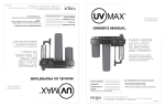
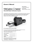
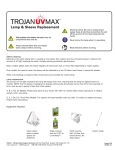
WHOLE HOME UV DISINFECTION SYSTEM
Model IHS12-D4
and IHS12-D4/2
OWNER'S MANUAL
PURIFY WATER
99.99% FREE
OF BACTERIA
AND VIRUSES!
Congratulations. By purchasing
this system, you have taken the
first step in ensuring safe drinking
water for your whole home.
Date of installation: Installed by: KEY INFORMATION YOU SHOULD KNOW:
• This product is for indoor use only.
Keep all components clean and dry.
• Clean the sleeve regularly for optimum performance
Installer phone #:
Serial #:
(Found on label on side of Power supply)
425 Clair Rd. W, Guelph, Ontario, Canada N1L 1R1
t. (+1) 519.763.1032 • tf. 1.800.265.7246 (US and Canada only) • t. +31 73 623 8116 (Europe only)
f. (+1) 519.763.5069 • e-mail: [email protected] www.viqua.com
520166-R
SAFETY INSTRUCTIONS
GROUNDING
This product must be grounded. If it should malfunction or breakdown, grounding provides a path of least resistance for electric current
to reduce the risk of electrical shock. This system is equipped with a cord having an equipment-grounding conductor and a grounding
plug. The plug must be plugged into an appropriate outlet that is properly installed and grounded in accordance with all local codes and
ordinances.
DANGER – Improper connection of the equipment-grounding conductor can result in a risk of electrocution. Check with a qualified
electrician or service personnel if you are in doubt as to whether the outlet is properly grounded. Do not modify the plug provided with
this system – if it will not fit the outlet, have a proper outlet installed by a qualified electrician. Do not use any type of adapter with this
system.
GROUND FAULT CIRCUIT INTERRUPTER PROTECTION
To comply with the National Electrical Code (NFPA 70) and to provide additional protection from the risk of electric shock, this system
should only be connected to a properly grounded, grounding-type power supply receptacle that is protected by a Ground Fault Circuit
Interrupter (GFCI). Inspect operation of GFCI as per manufacturers suggested maintenance schedule.
EXTENSION CORDS
If an extension cord is necessary, use only 3-wire extension cords that have 3-prong grounding-type plugs and 3-pole cord connectors
that accept the plug from this system. Use only extension cords that are intended for outdoor use. Use only extension cords having an
electrical rating not less than the rating of the system. A cord rated for less amperes or watts than this system rating may overheat.
Exercise caution when arranging the cord so that it will not be tripped over or pulled. Do not use damaged extension cords. Examine
extension cord before using and replace if damaged. Do not abuse extension cord. Keep extension cord away from heat and sharp
edges. Always disconnect the extension cord from the receptacle before disconnecting this system from the extension cord. Never yank
cord to pull plug from outlet. Always grasp the plug and pull to disconnect.
WARNING –
To guard against injury, basic safety precautions should be observed, including the following:
1. READ AND FOLLOW ALL SAFETY INSTRUCTIONS.
2.
3.
4.
5.
6.
7.
8.
9.
10.
11.
12.
13.
ANGER – To avoid possible electric shock, special care should be taken since water is employed in the use of this system.
D
Unless a situation is encountered that is explicitly addressed by the provided maintenance and troubleshooting sections, do
not attempt repairs yourself; refer to an authorized service facility.
CAUTION - Do not operate with broken or faulty parts as this may result in exposure to ultraviolet radiation. Contact supplier
for replacement parts.
Do not operate the system if it has a damaged cord or plug, or if it is malfunctioning or if it has been dropped or damaged in
any manner.
Always unplug the system, shut off water flow and release water pressure before servicing or cleaning. Never yank cord to
remove from outlet; grasp the wall plug and pull to disconnect.
Do not use the system for other than intended use. The use of attachments not recommended or sold by the manufacturer may
cause an unsafe condition.
To prevent risk of electrical shock, connect this system only to a properly grounded, grounding-type power supply receptacle
that is protected by a Ground Fault Circuit Interrupter (GFCI). Inspect performance of GFCI as per manufacturer’s suggested
maintenance schedule. If an extension cord is used, ensure it is of a sufficient rating and accepts the plug from this system;
never use an adapter.
Visually inspect this system prior to installation. If the quartz sleeve or lamp is broken, cracked or damaged in any way, do not
use. Contact the supplier for replacement parts.
Keep all connections dry and off the ground. Do not touch plug with wet hands.
The light emitted by the lamp will cause serious eye damage and burn unprotected skin. Do not plug system into an electrical
outlet without first properly securing the lamp into the chamber. Unplug the system prior to removing the lamp from the
chamber.
If the UV system malfunctions or fails, water must be boiled prior to consumption until the UV system is operational and the
water lines have been shocked. System failure is indicated by the system’s audible and visual alarms or the absence of any
indicator light.
Intended for indoor use only. System must not be exposed to weather elements. In seasonal applications, chamber must be
drained to prevent freezing.
Installation of this system must be in accordance with local plumbing and electrical codes as well as any and all applicable
regulations and laws.
14. SAVE THESE INSTRUCTIONS.
WARNING – To prevent risk of electrical shock, connect this system only to a properly grounded, groundingtype power supply receptacle that is protected by a Ground Fault Circuit Interrupter. Pull plug before
servicing or replacing lamp. Keep all connections dry and off the ground. Do not touch plug with wet hands.
WARNING – Do not look directly at UV lamp when it is operating. The light emitted by the lamp will cause
serious eye damage and burn unprotected skin.
WARNING – Read manual before installing or servicing this system. Only authorized personnel possessing
a strong understanding of this system should attempt to replace lamp or service this system.
NOTE – Maximum pressure rating is 125 PSI (8.62 bar)
OVERVIEW
TABLE OF CONTENTS
Overview
Specifications Components
Dimensions and layout
4
5
6
8
Operation
Control panel Troubleshooting
13
13
14
Maintenance
Sleeve cleaning and lamp replacement
H+, H
Warranty
15
15
J+, J
20
OPERATION
9
9
11
INSTALLATION
Installation
Installing the UV system
Disinfecting the water lines
MAINTENANCE
WARRANTY
OVERVIEW
SPECIFICATIONS
Specifications
Operating Parameters
Maximum operating pressure
125 PSI (862 kPa)
4 PSI (27.5 kPa)
Maximum ambient air temperature
122 0F (500C)
Minimum ambient air temperature
320F (00C)
Maximum humidity
100%
Maximum hardness
120 ppm
(7 grains per gallon)
Maximum iron
0.3 ppm
Minimum UVT
75%
INSTALLATION
Minimum operating pressure
Flow Rates*
Maximum rated flow at dose of 16 mJ/cm2
16 GPM (60 LPM)
Maximum rated flow at dose of 30 mJ/cm2
9 GPM (34 LPM)
Maximum rated flow at dose of 40 mJ/cm2
7 GPM (26 LPM)
Electrical
100-240V AC
Frequency
50-60 Hz
Max. current
0.5 Amp
Max. power consumption
50 Watts
Lamp power
40 Watts
Other
UV Chamber Material
304 SST
Inlet/Outlet
3/4" NPT
H+, H
J+, J
OPERATION
Voltage
Other
Rated service life of lamp
1 year
*Flow rates shown are at 85% UVT.
MAINTENANCE
UV System Certification
WARRANTY
5
For replacement components, please contact your installer (listed on the front of this manual) or contact VIQUA directly for a referral: 1 800 265 7246 (North America), 519 763 1032, or [email protected].
OVERVIEW
COMPONENTS
Components
1
2
3
1
Power supply mounting bracket
--
2
Reference card
603069
3
Power supply
(includes Power supply mounting bracket,
Reference card, Safety cap, Lamp cord)
650713-007
4
Power cord
602636 (120V)
INSTALLATION
Part
Number
Part
602637 (230V)
5
Safety cap
6
Lamp cord
4
--
J+, J
OPERATION
H+, H
603000
5
MAINTENANCE
6
WARRANTY
6
OVERVIEW
COMPONENTS
Components
7
602805
8
O-ring
--
9
Sleeve bolt
602665
Sleeve (includes O-rings)
602732
11
UV Chamber (includes Chamber
clamp(s), and Ring clamp).
--
12
Sediment filter
10" HIGH, 5 micron
CMB-510-HF
13
Carbon filter
20" HIGH, 5 micron
C2-02
14
Bracket
--
15
Sump wrench
WR-500
16
Drain Plug
--
17
O-ring
OR-5
10
7
8
9
H+, H
J+, J
8
10
OPERATION
Part Number
Lamp
(includes O-rings)
INSTALLATION
Part
14
12
7
11
16
WARRANTY
15
13
MAINTENANCE
17
OVERVIEW
DIMENSIONS AND LAYOUT
HOT WATER PIPE
Main Water
Shut Off
INSTALLATION
16” Clearance for
lamp removal
COLD WATER PIPE
7
Optional By-Pass Assembly
1
3
6
5
4
OPERATION
Optional
Water
Softener
25.5” Overall Length
2
WARRANTY
Main water shut-off valve.
2
Shut-off valve: Allows for ease of maintenance of whole home UV disinfection system.
3
Bypass shut-off valve: Bypass line and valve are optional. Intended to provide emergency water supply in the
event that the UV system is unavailable.
4
Shut-off valve: Allows for ease of maintenance of whole home UV disinfection system.
5
Whole Home System: Provides filtration and disinfection of the water.
6
Power supply: Powers and controls the UV lamp and other devices. Provides human interface, displaying
information and allowing control inputs (such as muting the audible alarm).
7
Power source: Provides power to the power supply. For safety reasons the outlet must be protected by a
Ground Fault Circuit Interrupter (GFCI). NOTE: to protect the power supply, a UL1449 certified
(or equivalent) transient voltage surge suppressor is required.
WARRANTY
1
MAINTENANCE
MAINTENANCE
MIN 4” from bottom of unit
for clearance for filter changes
8
6
2
Mount the system to the wall with
appropriate lag bolts through the
two mounting holes located on the
metal bracket. The supplied lag bolts
are suitable for attachment to wood.
(Attachments to other materials will
require purchasing of alternative
hardware).
7
3
Make all necessary plumbing
connections referring to Dimensions and Layout drawing. 8
Outlet must be
protected by a
Ground Fault
Circuit Interrupter
(GFCI).
OPERATION
Determine appropriate indoor location of
the power supply and chamber, referring
to Dimensions and Layout drawing.
Ensure adequate clearance above
chamber to allow for removal of the
lamp and sleeve. Make sure to turn off
the main water supply.
INSTALLATION
1
OVERVIEW
INSTALLING THE UV SYSTEM
Install sleeve bolt
with 2 o-rings.
4
9
Screw lamp into sleeve hand-tight.
Caution: Over tightening will break the
sleeve.
1
5
MAINTENANCE
Slide power
supply onto
mounting
bracket.
2
WARRANTY
Slide
Reference
card behind
power
supply.
9
Insert Lamp/
sleeve assembly
and screw into
chamber.
14
1
Caution: Over
tightening will
break the sleeve.
Proceed to Disinfecting The Water Lines.
2
INSTALLATION
11
Let water flow to one faucet or other water
outlet, then close the outlet and check for
leaks.
OVERVIEW
10
Align connections
by rotating ring
clamp to push
lamp plug onto
end of lamp.
ring
clamp
Attach ground (green/yellow) and strain
relief (red) wires from the lamp plug to
the ground lug on the chamber. Secure
both wires with locking screw provided.
13
Ground
lug
Ground and
strain relief
wires
MAINTENANCE
Locking
screw
OPERATION
12
Push safety
cap into
place.
WARRANTY
10
OVERVIEW
DISINFECTING THE WATER LINES
UV systems disinfect the water using ultraviolet light, treating the water as it passes through the
system. When there is a risk that water downstream of the UV system has been contaminated, it is
critical that these water lines be chemically disinfected. Disinfection of the water lines is therefore
required after initial system installation and following any period of time during which the system is
inoperative, whether due to an alarm condition, a power failure, or for any other reason. Make sure
the UV system is "on" during the entire disinfecting process.
Make sure power supply and lamp are
plugged in for entire disinfection process.
INSTALLATION
1
5
Caution: The
sump pumps
will be full of
water and will
be heavy.
2
6
OPERATION
WARRANTY
3
Relieve pressure
in the filter.
7
MAINTENANCE
1-2 cups
5.25% bleach
4
8
WARRANTY
11
Go to a water outlet and allow the cold
water to flow until you can smell bleach,
then stop the flow. Allow hot water (if
present) to flow until you can smell bleach,
then stop the flow. Repeat procedure at
all water outlets. Remember to include all
faucets, washing machines, toilets, outside
taps, and other water outlets. Note: You will
likely run out of bleach; if you cannot smell
bleach at a given outlet, turn off the main
water supply, depressurize and add more
bleach to the filter housing.
INSTALLATION
10
OVERVIEW
13
9
14
15
OPERATION
11
Let the bleach sit in the water lines for at
least four hours.
16
12
17
MAINTENANCE
Hold down PR button to purge air.
Flush all water outlets until bleach can no
longer be smelled (at least 5 minutes).
WARRANTY
12
CONTROL PANEL
OVERVIEW
A
1
2
B
C
3
INSTALLATION
Buttons and Display
Lamp timer
display
Counts down from 365 days to show time for annual lamp replacement.
B
Lamp timer
reset
After installing a new lamp, press and hold for five seconds to reset Lamp timer to
365.
C
Mute
Press to silence audible alarm.
OPERATION
A
When the alarm is due to the lamp's age, the mute button will silence the audible
alarm for 7 days; this may be repeated up to a maximum of 4 times. After that, the
button will silence for only 24 hours.
When the alarm is due to any other issue, the mute button will silence the audible
alarm for 24 hours.
Indicator lights only indicate a problem with the component when flashing red.
The table below is a list of possible causes and solutions. Before replacing parts, please contact VIQUA
Technical Assistance for any new troubleshooting techniques. 1-800-265-5774
Green
Yellow
Flashing red
Solid red
1
Option not available on
this system
Option not available on
this system
Option not available on
this system
Option not available on
this system
2
Lamp operating normally
Warning; lamp will require
replacement shortly
Lamp disconnected; unplug system,
reconnect lamp and plug-in system again
Lamp inactive due to power
supply failure
MAINTENANCE
Indicator lights
Lamp failure; replace lamp
13
Power supply operating
normally
Air temperature around
system is too warm
Power supply failure; replace power
supply
Power supply inactive due
to lamp failure
WARRANTY
3
OVERVIEW
TROUBLESHOOTING
The table below is a list of possible causes and solutions. Before replacing parts, please contact VIQUA
Technical Assistance for any other troubleshooting techniques. 1-800-265-7246
No power
GFCI and/or breaker tripped
Reset GFCI and/or breaker
Transient voltage surge suppressor (TVSS)
damaged
Replace TVSS
Power supply damaged
Replace power supply and use a TVSS
Connection between lamp and lamp plug
is wet
Clean and dry lamp pins and lamp plug,
check unit for leaks or condensation
Short-circuit in the electrical assembly
Replace power supply
Leak at inlet or outlet
Threaded pipe fittings are leaking
Clean threads, reseal with Teflon tape and
retighten
Leak detected from
area of UV chamber
Condensation of moist air on cold chamber
(slow accumulation)
Control humidity or relocate unit
O-ring damaged, deteriorated or incorrectly
installed
Inspect and replace if deteriorated
Lamp/sleeve assembly not properly installed
(too tight or not tight enough)
Tighten assembly hand-tight
Alarm
See Control Panel section on page 15
See Control Panel section on page 15
System is operating
but water tests
reveal bacterial
contamination
Equipment downstream of UV system is
acting as a breeding ground for pathogens
Ensure UV is the last piece of treatment
equipment
Pathogens are residing in the distribution
lines post-UV
Ensure all distribution lines have been
disinfected with chlorine - see Disinfecting
the Water Lines section
Recontamination from pipe dead-ends
Remove any pipe dead-ends and flush with
chlorine - see Disinfecting the Water Lines
section
Unit is unplugged
Plug unit into AC power outlet
No power at AC power outlet
Replace fuse or reset breaker
Power cord is damaged
Replace power cord
Power surge caused damage to electrical
assembly
Replace power supply and use a surge
protector (TVSS)
O-ring damaged, deteriorated or
incorrectly installed
Remove the sump, wipe the o-ring and
threads clean. ensure the o-ring is fitted
properly, then reinstall
Filter cartridge not centered
Remove sump, check for cartridge damage,
re-assemble ensuring cartridge is centered
GFCI or breaker
repeatedly trips
Lamp timer does not
read anything
Leak detected at
filters
MAINTENANCE
Possible solution
OPERATION
Possible cause
INSTALLATION
Symptom
WARRANTY
14
OVERVIEW
SLEEVE CLEANING & LAMP REPLACEMENT
Sleeve Cleaning:
Minerals in the water slowly form a coating on the sleeve. This coating must be removed because it
reduces the amount of UV light reaching the water, thereby reducing purification performance.
Please clean the sleeve regulary (3-4 times per year, or more often depending on water quality).
When only cleaning is required, follow instructions and re-install the current lamp.
INSTALLATION
Lamp Replacement:
The amount of UV light created by the lamp decreases over time, requiring that the lamp be replaced
every 12 months. NOTE: The UV system is designed to operate continuously and should not be shut
off for short periods of time, such as over a period of less than three weeks.
The system will automatically notify you after 12 months to replace the lamp. Follow these
instructions.
Scale remover such as
CLRTM or Lime-AwayTM.
MAINTENANCE
Gloves
OPERATION
Equipment required:
Cloth must be soft, lint-free, and
chemical-free. No clean-wipes.
WARRANTY
Each component of our UV products has been
designed and developed through extensive research
and development to be part of an overall system that
operates safely and effectively over its entire lifetime.
Using genuine parts for our UV systems not only
ensures the quality of the disinfection but also
ensures maintenance of your system warranty.
15
Relieve pressure
in the filter.
3
Strain relief
wires should
remain
connected.
7
Hold by
sleeve bolt
to remove
lamp/sleeve
assembly.
8
2
1
INSTALLATION
2
6
OVERVIEW
1
For sleeve cleaning only:
OPERATION
4
Let the system cool for 10 minutes.
Skip to step 13.
For lamp or sleeve replacement:
Clean sleeve and follow steps 9-12.
MAINTENANCE
Note: Sleeve must be replaced if it cannot be
completely cleaned or if it appears scratched or
cracked.
5
1
16
Squeeze
tabs
WARRANTY
2
12
OVERVIEW
9
Screw lamp into sleeve hand-tight.
Caution: Over tightening will break the
sleeve.
2
1
2
INSTALLATION
Lamp
tab
1
Sleeve
bolt
10
13
Caution: Over tightening
will break the sleeve.
1
OPERATION
Make sure lamp/sleeve
assembly is centered.
2
Remove o-rings
and sleeve bolt
from sleeve.
11
MAINTENANCE
Reinstall sleeve bolt
with 2 new o-rings.
WARRANTY
17
OVERVIEW
14
18
Align
connections by
rotating ring
clamp to push
lamp plug onto
end of lamp.
ring
clamp
Push safety
cap into
place.
19
Check for leaks.
INSTALLATION
15
16
OPERATION
17
If lamp was replaced:
Press and hold Lamp timer reset button for 5 seconds. Display should read 365.
MAINTENANCE
WARRANTY
18
OVERVIEW
CARTRIDGE REPLACEMENT
It is recommended to change the filter cartridges regularly, approximately 3-4 times per year
depending on water quality and usage. A gradual drop in water pressure after the filtration device is an indication that the pre-filter cartridges are nearing the end of their useful life.
1
6
INSTALLATION
Discard the used
cartridges and clean
the sump housing.
2
7
3
Relieve pressure
in the filter.
OPERATION
Install new cartridges
8
9
5
10
MAINTENANCE
4
WARRANTY
Press down the
pressure relief button
on top of the sump until air that might be present is purged
from filter.
19
Our Commitment
To maximize the superior quality of disinfection, each TrojanUVMax™ product must be properly installed, and maintained. If you experience difficulty
with your product, our Technical Support Centre is available to help you.
During the applicable warranty period noted below, we will provide warranty coverage, described below, for your product.
OVERVIEW
WARRANTY
How to Get Help
To obtain help under this warranty, contact the VIQUA Technical Support Center at 1 800 265 7246 or by email at [email protected]. Please have
available the model number, the date of purchase, the name of the dealer from whom you purchased your VIQUA product (“the source dealer”), as well as a description of the problem you are experiencing. A VIQUA technician will help you troubleshoot the problem and isolate the issue.
In order to establish proof of purchase when making a warranty claim, you will need your original invoice or complete and returned your warranty
card through the mail or online.
INSTALLATION
Specific Warranty Coverage
Warranty coverage is specific to the following TrojanUVMax™ products:
Ten-Year Limited Warranty for TrojanUVMax™ UV Chamber
VIQUA warrants the UV chamber on the TrojanUVMax™ products to be free from defects in material and workmanship for a period of ten (10) years
from the date of purchase. During this time, VIQUA will repair or replace, at its option, any defective TrojanUVMax™ UV chamber.
Please return the defective part to your dealer, who will return it to VIQUA - a Trojan Technologies Company. We will either make the necessary
repairs or, if it is determines that a replacement is required, will provide a replacement part. We will then return the part to the dealer. This warranty
does not include shipping and handling charges which will be collected from you by the dealer.
Parts repaired or replaced under this ten (10) year warranty will be covered under warranty to the end of the original ten (10) year warranty period.
This warranty is also subject to the conditions and limitations outlined under the heading "General Conditions and Limitations" below.
Three-Year Limited Warranty for Structural, Hardware and Electrical Components
VIQUA warrants the structural, hardware, and electrical components to be free from defects in material and workmanship for a period of three (3)
years from the date of purchase. During this time, VIQUA will repair or replace, at its option, any defective parts covered by the warranty.
Parts repaired or replaced under this three (3) year warranty will be covered under warranty to the end of the original three (3) year warranty period.
This warranty is also subject to the conditions and limitations outlined under the heading "General Conditions and Limitations" below.
One-Year Limited Warranty for Lamps and Sleeves
VIQUA warrants original lamps and sleeves to be free from defects in material and workmanship for a period of one (1) year from the date of
purchase. During this time, VIQUA will repair or replace, at its option, any defective parts covered by the warranty.
OPERATION
Please return the defective part to your dealer, who will return it to VIQUA - a Trojan Technologies Company. We will either make the necessary
repairs or, if VIQUA determines that a replacement is required, will provide a replacement part. We will then return the part to the dealer. This
warranty does not include shipping and handling charges which will be collected from you by the dealer.
The warranty period for lamps and sleeves may be verified using date codes in addition to purchase receipts and VIQUA's database of registered
owners. VIQUA will advise you whether the defective item needs to be returned to a VIQUA dealer for failure analysis. Replacement lamps and
sleeves provided under warranty will be sent to your TrojanUVMax™ dealer.
Warranty for Replacement Lamps and Parts
VIQUA warrants replacement lamps, purchased for annual routine maintenance, and other parts purchased to repair product components that are
no longer covered by the original warranty, to be free from defects in material and workmanship for a period of three (3) months from the date
of purchase. During this time, we will repair or replace, at its option, a defective replacement lamp or part free of charge except for shipping and
handling charges.
The warranty period on replacement lamps and parts will be verified using date codes and/or purchase receipts. VIQUA will advise you whether the
defective item needs to be returned to your dealer for failure analysis. Replacement lamps and parts provided under warranty will be sent to your
dealer.
MAINTENANCE
This warranty on lamps and sleeves does not include shipping and handling charges which will be collected from you by the dealer. Parts replaced
under this one (1) year warranty will be covered under warranty to the end of the original one (1) year warranty period. This warranty is also subject
to the conditions and limitations outlined under the heading "General Conditions and Limitations" below.
General Conditions and Limitations
None of the above warranties cover damage caused by improper use or maintenance, accidents, acts of God or minor scratches or imperfections
that do not materially impair the operation of the product. The warranties also do not cover products that are not installed as outlined in the
applicable Owner's Manual.
WARRANTY
The limited warranties described above are the only warranties applicable to the TrojanUVMax™ products listed. These limited warranties outline
the exclusive remedy for all claims based on a failure of or defect in any of these products, whether the claim is based on contract, tort (including
negligence), strict liability or otherwise. These warranties are in lieu of all other warranties whether written, oral, implied or statutory. Without
limitation, no warranty of merchantability or of fitness for a particular purpose shall apply to any of these products.
VIQUA - a Trojan Technologies Company does not assume any liability for personal injury or property damage caused by the use or misuse of any
of the above products. VIQUA shall not in any event be liable for special, incidental, indirect or consequential damages. VIQUA's liability shall, in
all instances, be limited to repair or replacement of the defective product or part and this liability will terminate upon expiration of the applicable
warranty period.
20
520166-R Printed in Canada. Copyright ©2010, VIQUA – a Trojan Technologies Company, Guelph, Ontario, Canada.