1
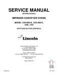
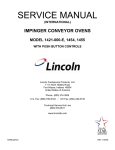
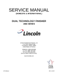
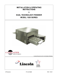
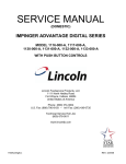
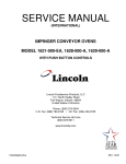
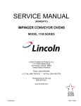
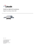
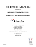
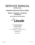
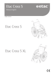
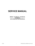
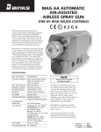
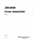
PARTS & SERVICE MANUAL
Impinger Advantage Gas w/ Push Button Controls
Advantage Digital Series - International
MODELS:
Please note that the model numbering system changed March
2007.The chart below shows the old model numbering system and
its matching new model number.
Old Model Number
1433-000-E
1433-000-E
1434-000-E
1434-000-E
1456
1457
→
→
→
→
→
→
→
New Model Number
1433-00z-U-Kxxxx (Europe)
1446-00z-U-Kxxxx (Asia)
1434-00z-U-Kxxxx (Europe, Middle East, Africa)
1447-00z-U-Kxxxx (Asia)
1446-00z-U-Kxxxx
1457-00z-U-Kxxxx
P/N: L371085
REV: 4.1.09
Lincoln Foodservice Products, LLC
1111 North Hadley Road
Fort Wayne, Indiana 46804
Telephone: 260.459.8200
Fax: 888.790.8193
Technical Support: 800.678.9511
lincolnfp.com
SEQUENCE OF OPERATION
IMPINGER ADVANTAGE
SERIAL NUMBER N28654 AND ABOVE
(OVENS WITH PUSH BUTTON CONTROLS)
MODEL 1433-000-E
MODEL 1434-000-E
MODEL 1456
MODEL 1457
POWER SUPPLY
CONTROL BOX AUTO
COOL DOWN
MAIN FAN CIRCUIT
BURNER CIRCUIT
TEMPERATURE CONTROL
CONVEYOR DRIVE
2
230VAC
230VAC
220/240VAC
220/240VAC
50 HZ.
50 HZ.
50 HZ.
50 HZ.
NAT. GAS
LP GAS
NAT. GAS
LP GAS
Electrical power is to be supplied to the oven by a three conductor
service.
Brown conductor is hot.
Blue conductor is neutral.
Green conductor is ground.
When the temperature in the control box reaches 120°F ± 3°F (48.9°C
± 1.7°C), the cooling fan thermostat will switch power to the control
box cooling fan. The thermostat will interrupt power to the cooling fan
when the control box temperature falls to 100°F ± 3°F (37°C ± 1.7°C).
Electrical power is permanently supplied, through the 10 Amp oven
fuse, to a normally open contact of the oven power switch. Power is
also supplied to the control box cooling fan. Closing the oven power
switch supplies line voltage to the main fan motor. Closing the oven
power switch also supplies line voltage to the heat circuit and to the
primary of the oven control transformer.
Closing the oven power switch supplies line voltage through the main
fan air pressure switch, through the normally closed oven cavity hi-limit
thermostat. Through the gas pressure proving switch (gas pressure
switch removed at S/N N31348) to the ignition control. The combustion
motor is now energized, the normally open combustion air switch
closes upon sensing air. After a pre-purge period between 30 and 60
seconds, the spark generator and the main gas valve are energized.
Ignition should now occur
Closing the oven fan switch supplies line voltage to the primary of the
control transformer and through the ignition control, to the oven
control. Secondary voltage, 24VAC, is supplied to the oven control.
The oven control is set to desired temperature. The thermocouple will
provide varying millivolts to the oven control. The oven control supplies
line voltage to the temperature regulation valve at intermittent intervals
to maintain desired temperature. The display on the oven control will
indicate when the temperature regulation valve is energized.
NOTE: The display also indicates oven temperature.
Closing the oven power switch supplies line voltage to the conveyor
motor and to the primary of the control transformer. Secondary
voltage, 24VAC, is supplied to the oven control. Setting the oven
control to the desired time outputs voltage, through a reversing switch,
to the conveyor motor.
NOTE: The conveyor system uses a hall effect sensor and magnet to
prove operation of the conveyor motor. If the motor is not running,
“BELT JAM” is indicated on the display.
Impinger I – Adv Digital – Gas Service Manual – International
SCHEMATIC DIAGRAM
MODEL 1433-000-E, 1434-000-E
SERIAL NUMBER N28654 TO N31348
Impinger I – Adv Digital – Gas Service Manual – International
3
SCHEMATIC DIAGRAM
MODEL 1456, 1457
SERIAL NUMBER N28654 TO N31348
4
Impinger I – Adv Digital – Gas Service Manual – International
SCHEMATIC DIAGRAM
MODEL 1433-000-E, 1434-000-E, 1456, 1457
SERIAL NUMBER N31349 AND ABOVE
Impinger I – Adv Digital – Gas Service Manual – International
5
TROUBLESHOOTING GUIDE
IMPINGER ADVANTAGE GAS OVENS
SERIAL NUMBER N28654 AND ABOVE
(OVENS WITH PUSH BUTTON CONTROLS)
SYMPTOM
Oven fan will not run
POSSIBLE CAUSE
Incoming power supply
Fuse, 10 Amp
Fuse holder
Switch, oven power
Motor, main fan
No control box cooling
Incoming power supply
Fuse, 10 Amp
Fuse holder
Switch, oven power
Cooling fan
No automatic control
box cooling
Incoming power supply
Cooling fan thermostat
Control box cooling fan
continues to run
Cooling fan thermostat
Oven will not heat
S/N N31348 and
Below
Main fan
Gas supply
Air pressure switch
Oven cavity hi-limit
thermostat
Gas pressure switch
6
EVALUATION
Check circuit breaker, reset if required. Check power
plug to be sure it is firmly in receptacle. Measure
incoming power, call power co. if required.
Check, replace if necessary.
Check, replace if necessary.
Check for line voltage supplied to switch. If no voltage is
present, trace wiring back to fuse holder. Check
continuity between switch terminals. Replace switch as
needed.
Check for line voltage supplied to motor. If no voltage is
present, trace wiring back to oven power switch. Check
motor for opens, shorts or grounds.
WITH POWER OFF: Turn fan blade to check for locked
rotor.
Check circuit breaker, reset if required. Check power
plug to be sure it is firmly in receptacle. Measure
incoming power, call power co. if required.
Check, replace if necessary.
Check, replace if necessary.
Check for line voltage supplied to switch. If no voltage
is present, trace wiring back to fuse holder. Check
continuity between switch terminals. Replace switch as
needed.
Check for supply voltage to the cooling fan. If no
voltage is present, trace wiring back to the fuse holder.
If voltage is present and motor does not run, check
motor for opens shorts or grounds.
WITH POWER OFF: Check for locked rotor.
Check circuit breaker, reset if required. Check power
plug to be sure it is firmly in receptacle. Measure
incoming power, call power co. if required.
Check cooling fan thermostat (thermostat closes at
120°F and opens at 100°F). With cooling fan thermostat
pre-heated, check for continuity
See “Cooling fan thermostat” (NOTE: Thermostat will
remain closed if control box temperature remains above
120°F.
If not operating, refer to “Oven fan will not run”
Check for adequate gas supply and be sure that the
manual gas shut off valve is open. Also check flexible
gas line connection.
Check air switch terminals for supply voltage to
terminals NO2 and COM. If voltage is present on one
side only, check for air tube blockage or misalignment. If
these are okay, adjust air pressure switch or replace
switch as needed.
Terminals are normally closed, opens at 350°C (660°F).
If open, reset and test oven for proper operation. If
thermostat will not hold for maximum temperature, and
oven is not exceeding control setting, check for proper
location of the capillary bulb in its spring holder. If above
checks are okay, replace hi-limit thermostat.
This switch is located inside the gas valve and should
close when gas pressure is present.
Impinger I – Adv Digital – Gas Service Manual – International
Ignition control
Burner reset switch
Burner blower motor
Burner blower motor air
pressure switch
Spark generator
Igniter/sensor assembly
Gas valve
Flame will not stay on
Flame sensor
Power supply
Ignition control
Impinger I – Adv Digital – Gas Service Manual – International
WITH POWER OFF: Remove 3 prong plug (on gas
valve) and measure continuity between terminals 2 and
3. If no continuity, check the following: Proper gas
pressure supply to gas valve as marked on the oven
specification plate. Check for proper adjustment of the
gas pressure switch, 10 for Nat. gas, 27 for LP gas or
4.5 for town gas. Check the filter in the gas valve for
blockage or damage. If above checks are okay, but
pressure switch is still not closed, replace gas valve.
Check for supply voltage to ignition control at terminal
#1 and neutral. If no voltage is present, trace wiring back
to gas pressure switch. If voltage is present, check for
supply voltage to burner blower motor at terminal #6 and
neutral. If no voltage is present, wait 30 seconds, reset
ignition control, and re- try. If the above fails, replace
ignition control.
Switch is normally open. Check to see that the switch
closes when reset button is pushed. Replace as needed.
Check for supply voltage to burner blower motor. If no
voltage is present, trace wiring back to the ignition
control.
WITH POWER OFF: Turn blower wheel to check for
locked rotor.
If supply voltage is present and motor does not run,
replace burner blower motor.
Check for supply voltage switching to terminal NO as the
air pressure switch closes. Check for air tube blockage
or misalignment, adjust air pressure switch. If the above
fails, replace air pressure switch.
After a pre-purge time of 30 to 60 seconds after burner
blower motor starts, check for supply voltage to spark
generator. If voltage is not present, check burner reset
switch. If voltage is still not present, replace ignition
control. If voltage is present, visually check for spark at
igniter.
Check for visible damage to the igniter/sensor assembly.
If there is no visible damage to the components, and no
spark, replace the spark generator. If there is visible
damage to the igniter/sensor assembly, replace. Also
check for frayed or damaged wires in burner tube.
Check for supply voltage to gas valve. If no voltage is
present, check reset button. Check all connections for
tightness. If there is still no voltage at the gas valve,
replace ignition control. If there is voltage present, check
for gas pressure at gas pressure tap located in gas
piping. If there is no gas pressure, replace gas valve.
Check for flame sensor operation, connect a digital
multimeter (capable of measuring DC microamps)
between the flame sensor wire and terminal #1 on the
ignition control. Sensor current is to be 3 microamps,
minimum. If these readings are not achieved, replace
igniter/sensor assembly. Also check for any type of
damage to flame sensor wire and connections.
NOTE: The DC microamp test must be conducted with
the oven in low flame (bypass) operation.
Set the temperature to the lowest temperature setting. If
there is sufficient microamp current, but the flame will
not stay on, check for proper polarity of the power
supply.
If there is sufficient microamp current, and there is
proper polarity of the power supply, but the burner will
7
Oven will not heat
S/N N31349 and
Above
Main fan
Gas supply
Air pressure switch
Oven cavity hi-limit
thermostat
Ignition control
Burner reset switch
Burner blower motor
Burner blower motor air
pressure switch
Ignition control
Igniter/sensor assembly
Ignition control
Gas valve
8
not stay on, check the reset button for the ignition
control. If the above check okay, replace ignition control.
If not operating, refer to “Oven fan will not run”
Check for adequate gas supply and be sure that the
manual gas shut off valve is open. Also check flexible
gas line connection..
Check air switch terminals for supply voltage to
terminals COM and NO. If voltage is present on one side
only, check for air tube blockage or misalignment. If
these are okay, adjust air pressure switch or replace
switch as needed.
Terminals are normally closed, opens at 350°C (660°F).
If open, reset and test oven for proper operation. If
thermostat will not hold for maximum temperature, and
oven is not exceeding control setting, check for proper
location of the capillary bulb in its spring holder. If above
checks are okay, replace hi-limit thermostat.
Check for supply voltage to ignition control at terminal
#1 and neutral. If no voltage is present, trace wiring back
to hi-limit thermostat. If voltage is present, check for
supply voltage to burner blower motor at terminal #8 and
neutral. If no voltage is present, wait 30 seconds, reset
ignition control, and re- try. If the above fails, replace
ignition control.
Switch is normally open. Check to see that the switch
closes when reset button is pushed. Replace as needed.
Check for supply voltage to burner blower motor. If no
voltage is present, trace wiring back to the ignition
control.
WITH POWER OFF: Turn blower wheel to check for
locked rotor.
If supply voltage is present and motor does not run,
replace burner blower motor.
Check for air pressure switch to be switching from “NC”
to “NO”. Check for air tube blockage or misalignment.
Adjust air pressure switch. If the above fails, replace air
pressure switch.
A pre-purge time of 30 to 60 seconds occurs after
burner blower motor starts. Check for high voltage spark
output from the ignition control. If there is no high
voltage spark output, check reset button for the ignition
control. If there is still no high voltage output, replace the
ignition control.
Check for visible damage to the igniter/sensor assembly.
If there is visible damage to the igniter/sensor assembly,
replace. If there is no visible damage to the components,
and no spark, replace the igniter/sensor assy. Also
check for frayed or damaged wires in burner tube.
Replace components as needed.
Gas valve should open as the ignition control generates
the high voltage spark. Check for supply voltage to pilot
valve at terminal #5 and neutral. If no voltage is present,
check reset button for the ignition control. If there is still
no voltage to the pilot valve, replace ignition control.
Check for supply voltage to pilot valve terminal #5 to
neutral, if there is no voltage, trace wiring back to
ignition control. If there is supply voltage, connect a
manometer to the pressure tap fitting on the gas valve. If
Impinger I – Adv Digital – Gas Service Manual – International
Pilot tube
Pilot orifice
Flame will not stay on
Flame sensor
Power supply
Ignition control
Low flame is on, but
no main flame
NOTE: Flame should be on at
this time
Control transformer
Oven control
Thermocouple
Impinger I – Adv Digital – Gas Service Manual – International
there is voltage to the pilot valve, but there is no gas
pressure, replace gas valve.
Check for gas pressure at pilot tube. Disconnect pilot
tube at burner and connect manometer. If there is no
gas pressure, check for blockage in pilot tube. Repair or
replace as needed.
If there is gas pressure at the pilot tube, check the pilot
orifice for damage or obstructions. Replace pilot orifice
as needed.
To check flame sensor operation, connect a digital
multimeter (capable of measuring D.C. microamps)
between the flame sensor wire and the flame sensor
connection on the ignition control (terminal #13). Flame
sensor current is to be 0.7 microamps, minimum. If
these readings are not achieved, replace igniter/sensor
assembly. Also check for any type of damage to flame
sensor wire and connections.
NOTE: The D.C. microamp test must be conducted with
the oven in low flame (bypass) operation.
Set the temperature to the lowest temperature setting. If
there is sufficient microamp current, but the flame will
not stay lit, check for proper polarity of the power supply.
If there is sufficient microamp current, and there is
proper polarity of the power supply, but the burner will
not stay lit, check the reset button for the ignition control.
If the above test is okay, replace the ignition control.
Check for supply voltage to primary of control
transformer. If no voltage is present, trace wiring back to
oven power switch. If voltage is present, check for
24VAC at transformer secondary. If there is primary
voltage, but no secondary voltage, replace control
transformer.
Check for 24VAC supply to oven control. If no voltage is
present, trace wiring back to control transformer. Check
for supply voltage to oven control. If no voltage is
present, trace wiring back to ignition control. If voltage is
present, check for a read-out on the display. If there is
no read-out on the display, replace oven control. If there
is a read-out on the display, set the oven control to
maximum temperature (see installation operations
manual for temperature adjustment). With the oven
control at maximum temperature, check for supply
voltage to the temperature regulation valve. If there is
voltage at the temperature regulation valve, proceed to
“Temperature regulation valve “. If there is no voltage at
the temperature regulation valve, trace wiring back to
the oven control. If there is no voltage output at the oven
control, check the read-out on the oven control. If the
oven control reads “PROBE FAIL” this indicates that the
thermocouple has failed or become disconnected from
the oven control
Check to see that the thermocouple is securely
connected to the oven control. If the thermocouple is
connected to the oven control, and the display indicates
“PROBE FAIL”, disconnect the thermocouple from the
oven control and measure the resistance of the
thermocouple. The thermocouple should read approx.
11Ω. If these readings are not achieved, replace the
thermocouple. If these readings are correct, proceed.
9
Oven control
Thermocouple
Oven control
Temperature regulation valve
Intermittent heating
Thermal/overload of main fan
and burner blower motor
Conveyor will not run
Incoming power supply
Fuse, 10 Amp
Fuse holder
Switch, oven power
Control transformer
Conveyor motor
Capacitor, conveyor motor
Switch, conveyor reversing
Oven control
Conveyor motor runs,
but there is no speed
display
NOTE: Display will indicate
“BELT JAM”
Oven control
10
If the thermocouple checks good, but the oven control
display indicates that there is a thermocouple failure,
replace the oven control. If the oven control indicates a
temperature reading, but the oven will not heat, proceed.
WITH POWER ON AND THERMOCOUPLE
ATTACHED TO THE OVEN CONTROL: Measure the
DC millivolt output of the thermocouple. Refer to the
thermocouple chart (located in the “Removal” section of
the manual) for proper millivolt readings. If these
readings are not achieved, replace thermocouple.
If the thermocouple checks good, but there is no supply
voltage output to the temperature regulation valve,
replace the oven control. If there is supply voltage output
to the temperature regulation valve, proceed.
Check for supply voltage to the temperature regulation
valve. If voltage is present, listen for valve to open and
close. Also check for opens or shorts in the operating
coil. Replace temperature regulation valve as needed.
The main fan motor and burner blower motor are
equipped with internal thermal protection and will cease
to operate if overheating occurs. As the motors overheat
and cool, this will cause the heating system to cycle on
and off intermittently. Improper ventilation or lack of
preventive maintenance may cause this problem. Also
most of the problems listed under “Oven will not heat”
can cause intermittent failure.
Check circuit breaker, reset if required. Check power
plug to be sure it is firmly in receptacle. Measure
incoming power, call power co. if required.
Check, replace if necessary.
Check, replace if necessary.
Check for line voltage supplied to switch. If no voltage
is present, trace wiring back to fuse holder. Check
continuity between switch terminals. Replace switch as
needed.
Check for supply voltage to primary of control
transformer. If no voltage is present, trace wiring back to
oven power switch. If voltage is present, check for
24VAC at transformer secondary. If there is primary
voltage, but no secondary voltage, replace control
transformer.
Check for supply voltage to the conveyor motor at
terminal #6 to neutral. If no voltage is present, trace
wiring back to oven power switch. If voltage is present,
but the motor will not run, check the motor windings for
opens or shorts. If any of the above checks fail, replace
conveyor motor.
Check for shorts or grounds. Replace capacitor as
needed.
WARNING: Capacitor has a stored charge, discharge
before testing.
Check continuity between switch terminals. Replace
switch as needed.
If there is voltage supplied to the motor, and the motor
capacitor and reversing switch check good, replace the
oven control.
Check for output voltage from oven control to hall effect
Impinger I – Adv Digital – Gas Service Manual – International
Conveyor motor
Oven control
Impinger I – Adv Digital – Gas Service Manual – International
sensor (sensor is located in the conveyor motor).
Measure voltage at the motor connector, red wire and
yellow wire. Voltage should be approx. 10VDC. If no
voltage is present, trace wiring back to oven control. If
there is no voltage output at the oven control, replace
oven control.
If there is voltage supplied to the hall effect sensor,
check for a frequency output from the hall effect sensor.
Measure frequency across the yellow and white wires in
the motor connector. Frequency reading should be
approx. 25-100 Hz. If these readings are not achieved,
replace conveyor motor. If the readings are achieved,
proceed.
If the hall effect sensor readings are correct, but there is
no speed indicated on the display, replace the oven
control.
11
REMOVAL, INSTALLATION & ADJUSTMENTS
IMPINGER ADVANTAGE SERIES
CAUTION!
BEFORE REMOVING OR INSTALLING ANY COMPONENT IN THE IMPINGER
OVEN BE SURE TO DISCONNECT ELECTRICAL POWER AND GAS SUPPLY
MOTOR, MAIN FAN - REPLACEMENT
1. Shut off power at main breaker.
2. Remove louvered motor cover from back of oven.
3. Remove wireway by taking out the (5) five hex screws.
4. Disconnect wiring from motor.
5. Remove the twelve (12) hex head bolts from the oven back and slide back straight out of the oven.
6. Remove two (2) bolts from fan hub and remove fan from motor shaft.
NOTE: Measure distance from fan blade to rear wall assembly before removal to aid in reassembly.
7. Remove the eight (8) hex head bolts from the motor mount and slide the motor assembly out of the oven back.
8. Remove motor by taking off motor clamp and removing the four (4) mounting nuts and washers.
9. Reassemble in reverse order. When motor mount assembly is set on the oven back, align motor shaft in the center
of the hole. Set fan assembly on the motor shaft.
NOTE: A. Torque specs on bolts (150 in/lb. torque)
B. It is recommended that an anti-seize compound be brushed on to the bolts around
the back and motor mount bracket before assembly.
FAN, MAIN - REPLACEMENT
Shut off power at main breaker.
Remove back assembly. (See MOTOR, MAIN FAN))
Reinstall and locate fan so that the bottom of the fan spider is 1 1/2" from the top of the oven back cone. (See Drawing)
FAN SPIDER
NOTE: MEASUREMENT MUST BE
MADE FROM CONE TO FAN SPIDER
FAN HUB
1 1/2 INCH
CONE
CAPACITOR, MOTOR - REPLACEMENT
1. Shut off power at main breaker.
2. Remove motor cover from back of oven.
3. Discharge capacitor.
4. Remove and replace.
COOLING FAN, CONTROL BOX - REPLACEMENT
1. Shut off power at main breaker.
2. Remove control panel top and front cover.
3. Remove four (4) screws from the fan frame.
4. Disconnect cord and plug and remove fan.
5. Reassemble in reverse order.
12
Impinger I – Adv Digital – Gas Service Manual – International
THERMOSTAT, COOLING FAN - REPLACEMENT
1. Shut off power at main breaker.
2. Remove control panel top and front cover.
3. Remove lead wires and mark for reassembly.
4. Remove two (2) screws and remove thermostat.
5. Reassemble in reverse order.
BURNER BLOWER MOTOR - REPLACEMENT
1. Shut off power at main breaker.
2. Remove control panel top and front cover.
3. Unplug motor connector.
4. Remove three (3) screws from blower tube at burner housing.
5. Remove air shutter assembly from old motor for installation on new
motor assembly.
6. Reassemble in reverse order and check system operation.
NOTE: Check air shutter adjustment and adjust if necessary
Set air shutter at approx. 1/4" and adjust to get a blue flame
with an occasional tip of yellow under high flame. A view
port in the burner assembly should be used to observe flame.
BLOWER WHEEL, BURNER
This is part of the burner blower motor assembly.
TO REMOVE THE BLOWER WHEEL FOR PERIODIC CLEANING:
1. Shut off power at main breaker.
2. Remove control panel top and front cover.
3. Remove air shutter held by 3 screws.
4. Loosen set screws on blower wheel hub and pull straight out.
5. Reassemble in reverse order.
NOTE: There is no critical placement of the blower wheel on the motor shaft. Just back as far as
it will go and then spin the blower to be sure it is not rubbing.
BURNER CONTROL – REPLACEMENT (S/N N31348 and Below)
1. Shut off power at main breaker.
2. Remove control panel top and front cover.
3. Remove front portion of control by releasing tabs on sides and pulling out (rocking motion).
4. Remove wires from plug in terminal strip, note wire numbers and location.
5. Remove two screws from mounting bracket and remove.
6. Reassemble in reverse order and check system operation.
BURNER CONTROL – REPLACEMENNT (S/N N31349 and above)
1. Shut off power at main breaker.
2. Remove control panel top and front cover.
3. Remove wires from control. Mark all wiring for reassembly.
4. Remove two mounting screws from control and remove control.
5. Reassemble in reverse order and check system operation.
BURNER ASSEMBLY
1. Shut off power at main breaker.
2. Shut off gas supply.
3. Remove control panel top and front panel.
4. Remove gas control valve (See "GAS CONTROL VALVE")
5. Disconnect pilot tube.
6. Remove solenoid valve. (See "TEMPERATURE REGULATION VALVE")
7. Remove four (4) screws that secure the burner backing plate.
Impinger I – Adv Digital – Gas Service Manual – International
13
8. Remove burner assembly from housing, the main and pilot orifice, flame target, pilot shield
(main and extension), burner ignitor can now be changed or serviced as needed.
9. Reassemble in reverse order. Check all gas line fittings for leaks.
GAS CONTROL VALVE – REPLACEMENT (S/N N31348 and Below)
1. Shut off power at main breaker.
2. Shut off gas supply.
3. Remove control panel top and front cover.
4. Remove the four screws from the incoming nipple mounting bracket and remove pipe.
5. Disconnect two plugs from gas control valve and mark locations.
6. Remove pilot tube assembly from gas control valve.
7. Disconnect pipe union just above temperature regulation valve.
8. Remove piping from old valve for installation on new valve.
9. Reassemble in reverse order. Check all gas line fittings for leaks. After assembling, check for proper adjustment of
gas pressure switch, 10 on dial for natural gas, 27 for LP gas or 4.5 for town gas.
10. Check and adjust manifold pressure. Remove pressure tap located in gas piping and install manometer.
Adjustment screw is located on the front of the valve, adjust as needed. 2.5” W.C. for natural gas, 10” for LP or
2.0” W.C. for town gas.
11. Check filter by removing cover plate (located on either side of valve). Remove four screws and slide filter out of
valve and inspect. Reassemble in reverse order and check for leaks.
GAS CONTROL VALVE – REPLACEMENT (S/N N31349 and Above)
1. Shut off power at main breaker.
2. Shut off gas supply.
3. Remove control panel top and front cover.
4. Disconnect the gas piping from the back of the unit.
5. Remove the mounting screw from the incoming pipe nipple and remove the incoming piping nipple.
6. Remove pilot tube assembly from gas valve.
7. Disconnect wiring from gas valve. Mark all wiring for reassembly.
8. Disconnect pipe union and remove gas valve.
9. Remove piping from old valve and reassemble in reverse order.
10. Check system for proper operation. Check all gas line fittings for leaks.
11. Adjust the gas manifold pressure on the gas valve. Refer to the specification plate on the oven for proper rating.
TEMPERATURE REGULATION VALVE - REPLACEMENT
1. Shut off power at main breaker.
2. Shut off gas supply.
3. Remove control panel top and front cover.
4. Remove gas control valve (See "GAS CONTROL VALVE")
5. Disconnect wires from temperature regulation valve.
6. Remove two (2) hex nuts that hold main orifice bracket in place.
7. Remove temperature regulation valve assembly.
8. Remove piping from temperature regulation valve.
9. Reassemble in reverse order.
10. Check all fittings for leaks.
SWITCH, BURNER RESET – REPLACEMENT
1. Shut off power at main breaker.
2. Remove control box cover and front panel.
3. Disconnect reset switch wires from burner control and mark for reassembly.
4. Pull off black button from switch and remove mounting nut. Remove switch from control box.
5. Reassemble in reverse order and check system operation.
14
Impinger I – Adv Digital – Gas Service Manual – International
THERMOSTAT, OVEN CAVITY HI-LIMIT – REPLACEMENT
1. Shut off power at main breaker.
2. Remove control box cover and front panel. Remove conveyor assembly and fingers from oven to aid in removal of
thermostat from oven.
3. Disconnect wires from thermostat and mark for reassembly.
4. Remove thermostat from oven.
5. Reassemble in reverse order and check system operation.
BURNER IGNITOR - REPLACEMENT
1. Shut off power at main breaker.
2. Remove control panel top and front cover.
3. Remove burner assembly. (SEE "BURNER ASSY.")
4. Remove pilot shield and pilot shield extension.
5. Remove burner ignitor.
6. Reassemble in reverse order (spark gap approx. .100 in. or 2.5 mm)
NOTE: Be sure to reconnect burner ignitor cable to ignition control.
BURNER ALARM – REPLACEMENT
1.
2.
3.
4.
5.
Shut off power at main breaker.
Remove control panel top and front cover.
Remove two wires from alarm and mark for reassembly.
Remove mounting ring from burner alarm and remove alarm.
Reassemble in reverse order and check system operation.
SPARK GENERATOR – REPLACEMENT
1.
2.
3.
4.
5.
Shut off power at main breaker.
Remove two wires for spark generator.
Unplug connector on bottom of spark generator.
Remove two mounting screws and remove spark generator.
Reassemble in reverse order and check system operation.
AIR PRESSURE SWITCH – REPLACEMENT
1. Shut off power at main breaker.
2. Remove control panel top and front cover.
3. Disconnect wires from air pressure switch and mark for reassembly.
4. Remove air switch tube from air pressure switch.
5. NOTE: There are two types of air pressure switches used. Remove air pressure switch from its mount.
6. Reassemble in reverse order and check system operation.
7. To adjust air pressure switch, remove cover from switch to expose adjusting screw. To increase sensitivity, turn
screw counter-clockwise. To decrease sensitivity, turn screw clockwise.
THERMOCOUPLE (TYPE K) - REPLACEMENT
1. Shut off power at main breaker.
2. Remove control panel top and front cover.
3. Slide thermocouple out of oven chamber.
NOTE: Remove conveyor and bottom fingers to aid in removal and installation of thermocouple.
4. Remove two (2) wires from temperature control. Make note of wire numbers or color and
location for reinstallation.
5. Reassemble in reverse order making sure the metal end on the thermocouple is in the wire form in the oven
chamber.
Impinger I – Adv Digital – Gas Service Manual – International
15
THERMOCOUPLE MEASURMENT
TEMPERATURE
200°
250°
300°
350°
400°
450°
500°
550°
600°
D.C. MILLVOLTS (APPROX.)
2.8
4.0
5.1
6.0
7.1
8.2
9.3
10.4
11.5
CONTROL TRANSFORMER - REPLACEMENT
1. Shut power off at main breaker.
2. Remove control panel top and front cover.
3. Remove two (2) wires on primary side, note color and location.
4. Remove two (2) wires on secondary side, note color and location.
5. Remove two (2) screws from transformer base and replace assembly.
6. Reinstall in reverse order and check system operation.
CONVEYOR DRIVE MOTOR - REPLACEMENT
1. Shut power off at main breaker.
2. Remove control panel top and front cover.
3. Loosen set screw on conveyor drive sprocket and slide sprocket off shaft.
4. Disconnect motor plug.
5. Remove four (4) screws from motor frame, on control box side, and remove motor assembly.
6. Reassemble in reverse order making sure to align chain sprockets and adjust motor for proper chain tension
(1/2" SAG).
CAPACITOR, CONVEYOR MOTOR – REPLACEMENT
1.Shut off power at main breaker.
2.Remove control box cover and front panel.
3.Discharge capacitor before removing wires. Mark wires for reassembly.
4.Remove mounting screw and remove capacitor.
5.eassemble in reverse order and check system operation.
REVERSING SWITCH – REPLACEMENT
1. Shut off power at main breaker.
2. Remove control box cover and front panel.
3. Disconnect wires from reversing switch and mark for reassembly.
4. Remove mounting nut and remove reversing switch.
5. Reassemble in reverse order and check system operation.
REVERSING CONVEYOR DIRECTION
All ovens leaving our plant are wired to operate conveyors from left to right. To reverse conveyor
direction, use the following procedure.
1. Shut off power at oven switch.
2. Set conveyor reversing switch in the other position.
3. Turn oven “on” and check for proper operation.
MAIN ORIFICE - REPLACEMENT
1. Shut off power at main breaker.
2. Remove control panel top and front panel.
3. Remove gas control valve assy.
4. Remove two (2) nuts from burner orifice bracket.
5. Disconnect pipe union.
16
Impinger I – Adv Digital – Gas Service Manual – International
6. Remove assembly and replace main orifice.
7. Reassemble in reverse order and check system operation.
NOTE: Check all gas line fittings for leaks.
PILOT ORIFICE - REPLACEMENT
1. Shut off power at main breaker.
2. Shut off gas supply.
3. Remove burner assembly (See "Burner Assembly").
4. Remove pilot line from pilot orifice.
5. Remove pilot orifice from burner ignitor.
6. Reassemble in reverse order.
NOTE: Check all gas line fittings for leaks.
ON-OFF SWITCH - REPLACEMENT
1. Shut off power at main breaker.
2. Remove control box cover.
3. Remove access cover.
4. Depress spring clips on side of switch and push out.
5. Remove wires from back of switch, note wire number and location.
6. Reassemble in reverse order and check system operation.
NOTE: Make sure switch housing is fully seated in control box housing.
OVEN CONTROL – REPLACEMENT
A.
B.
C.
D.
E.
F.
G.
Shut off power at main breaker.
Remove control box cover and front panel.
Remove all wiring connections and mark for reassembly.
Remove oven control by pulling control from the mounting pins. Remove control from oven.
Before installing new oven control, set voltage jumper (located at the bottom center of the
oven control) to the proper voltage (120V/240V) position. Install the four pushbutton extensions
(included with the oven control) by pushing the extensions onto the four set buttons on control.
Reassemble in reverse order and check system operation.
Set the oven control for the proper operating mode. The 1400 series ovens use a single temperature control
system. The oven control must be set to the proper operating mode. Set the control as follows: With the oven
power switch “off”, depress the “time” and “up” buttons and turn the oven “on”. Control will indicate
“Imp I or Imp II” Release the buttons. Press the “up” or “down” button until “Imp I” and “temp to store” appears
on the display. Press the “temp” button. The control is now set for Impinger I conveyor and single burner
operation.
FUSE HOLDER – REPLACEMENT
1.
2.
3.
4.
5.
Shut off power at main breaker.
Remove control box cover.
Remove all wiring from fuse holder and mark for reassembly.
Remove mounting nut for fuse holder and remove fuse holder.
Reassemble in reverse order and check system operation.
BEARING, CONVEYOR – REPLACEMENT
1.
2.
3.
4.
5.
Remove conveyor from oven and place on flat work surface.
Remove connecting links from conveyor belt. See Installation and operations manual.
Remove conveyor belt from conveyor. Remove drive sprocket from drive shaft if required.
Move shaft toward end of conveyor, and shaft with bearings will now slip out of holding bracket.
Replace bearing and reassemble in reverse order.
Impinger I – Adv Digital – Gas Service Manual – International
17
GENERAL VIEW
ADVANTAGE SERIES
LETTER
A
B
C
D
E
F
G
H
J
K
L
M
N
O
P
Q
R
S
T
U
V
W
X
Y
Z
*
AA
BB
CC
DD
EE
FF
GG
HH
JJ
KK
LL
MM
NN
OO
PP
QQ
18
PART NUMBER
369003
369110
369337
369929
369828
369209
369310
369308
369334
369309
350638
369311
369336
369906
370110
369157
1534
369057
369643
1009
369062
369140
369903
369141
369139
369058
369211
369203
369749
369204
369373
369748
369328
369052
369030
369904
369053
369055
369218
369926
369925
369927
DESCRIPTION
Door hinge
Access window assembly
Retainer (old style)
Retainer (new style)
Handle spacer
Latch & strike
Screw, 6-32 x 3/16”
Bottom, access window
Access door glass
Top, access window
Handle
Handle spacer (2 req.)
Door latch
Screw, 8-32 x 5/8”
Door assembly (solid)
Door assembly (with window)
Finger support assembly
Support bracket pin
Strike assembly
Oven top
Top, control box
Compression spring
Washer, flat
Conveyor hold down bracket
Shoulder screw
Baffle, inlet and outlet
Thumb screw (not shown)
Stud, wing head
Chain cover kit (includes AA, CC)
Split ring retainer
Receptacle, snap –in
Bracket, chain cover
Leg, stand
Adjustable leg
Caster, 6”
Insulation holder assembly
Finger housing
Columnating plates –
see installation operations manual
Finger cover
Crumb pan, internal
Window frame, bottom
Glass, access window
Window frame, top
Impinger I – Adv Digital – Gas Service Manual – International
Impinger I – Adv Digital – Gas Service Manual – International
19
CONTROL BOX
1456,1457,1433-000-E, 1434-000-E
LETTER
A
B
C
D
E
F
G
H
I
J
K
L
M
N
O
P
Q
R
S
T
U
V
W
X
Y
Z
AA
BB
CC
DD
EE
FF
GG
HH
II
Not shown
Not shown
20
PART #
369062
370355
370363
370354
369432
369580
370433
369570
369571
370186
369072
369099
370114
369144
369202
369076
369075
369142
370362
369589
369399
369400
369158
370373
370359
369368
369378
369507
369025
369575
369192
370360
369574
369579
370241
369573
370396
369331
369073
369100
357107
369014
DESCRIPTION
Top, Control Panel
Oven Control
Front Cover Assembly
Facia, Label
Switch, On/Off
Gas Valve, Multi Block (S/N N31348 & Below)
Gas Valve (S/N N31349 & Above)
Connector, 3 Pole
Connector, 4 Pole
Solenoid Valve
Main Orifice, Nat.
Main Orifice, LP
Main Orifice, Town Gas
Pilot Shield Extension
Pilot Shield, Main
Burner Igniter
Flame Sensor
Flame Target
Thermocouple (Type K)
Blower Motor
Air Shutter Assembly
Shutter, MVB Air Plate
Drive Sprocket
Conveyor Motor
Reversing Switch
Thermostat, Hi-Limit
Cooling Fan
Cooling Fan Thermostat
Blower Air Switch
Air Pressure Switch
Capacitor
Capacitor, Conveyor Motor
Spark Generator (S/N N31348 & Below)
Solid State Alarm
Transformer, Control
Ignition Control (S/N N31348 & Below)
Ignition Control (S/N N31349 & Above)
Finger Guard
Bypass Orifice, NAT
Bypass Orifice, LP
Fuse holder
Fuse, 10 A.
Impinger I – Adv Digital – Gas Service Manual – International
Impinger I – Adv Digital – Gas Service Manual – International
21
OVEN BACK
ADVANTAGE SERIES
GAS AND ELECTRIC
LETTER
A
B
C
D
E
F
G
H
J
K
M
22
PART NUMBER
369808
370140
369214
369033
369215
369192
369306
369646
369647
369213
369547
369287
369315
369122
DESCRIPTION
Cover, motor (gas ovens)
Cover, motor (electric ovens)
Motor, main fan (50 Hz.)
Motor clamp
Motor support assembly
Capacitor, 7.5 MFD
Oven back assembly, gas oven
Stand-off
Inlet panel
Main fan
Bracket, thermostat
Heating element, 208V
Heating element, 220V
Heating element, 240V
Impinger I – Adv Digital – Gas Service Manual – International
Impinger I – Adv Digital – Gas Service Manual – International
23
CONVEYOR
1450 SERIES
LETTER
A
B
C
D
E
F
G
H
J
K
L
M
24
PART NUMBER
369830
369816
369163
370092
369362
369825
369813
369314
369812
369160
369814
369005
369811
369161
369806
370050
369162
DESCRIPTION
Complete conveyor assembly
Conveyor belt, complete (30 inch wide belt)
Conveyor belt, complete (32 inch wide belt)
Conveyor belt, 1 foot section (30 inch wide belt)
Conveyor belt, 1 foot section (32 inch wide belt)
Retaining ring
Conveyor bearing block
Roll, conveyor, notched
Conveyor idler shaft
Conveyor pan stop
Connecting link (30 inch wide belt)
Connecting link (32 inch wide belt)
Conveyor drive shaft
Roller chain sprocket
Crumb pan
Conveyor frame
Drive chain
Impinger I – Adv Digital – Gas Service Manual – International
Impinger I – Adv Digital – Gas Service Manual – International
25
This page intentionally left blank.
26
Impinger I – Adv Digital – Gas Service Manual – International
This page intentionally left blank.
Impinger I – Adv Digital – Gas Service Manual – International
27
28
Impinger I – Adv Digital – Gas Service Manual – International