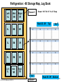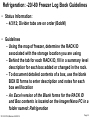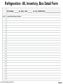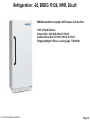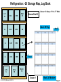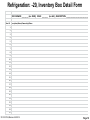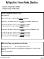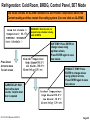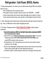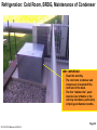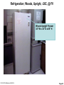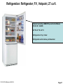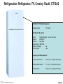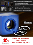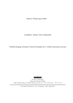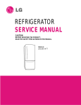
1
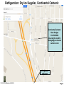
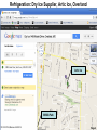
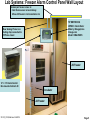
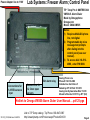
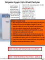
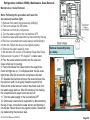
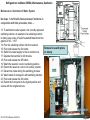
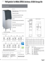
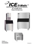
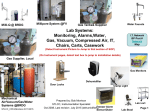
-20C @FV -80°C @FV Cold Room Walk-in 4C -85°C, @BRDG Scotsman Flaker @BRDG Chiller- @ BRDG Bioprocessing -20 Refrigeration BRDG Ice-o-Matic Flaker @ FV Marvel 5 cuft Freezer Alarm Sensor/Dialer@ BR Bench Minifridge Boekel II Refrigeration Freezers Link to SERVICE/REPAIR INFO Cryogenic LN2@ BRDG Prepared by: Bob Morrison Refrigeration Cryogenic Office Refrigerator at Instrumentation Specialist Crosley 15cft Dewar BRDG STLCC-CPLS;Morrison 3/24/2015 Initial version Oct 08, Last Revision Dec14 (Marvel) @FV Refrig/Freezer 27 cuft Hotpoint @FV Page 1 Refrigeration: Service and Emergency Outage Plan For all Refrigerators or Freezers except the Cold Room: Ace Lab Systems 1550 S. Kingshighway St. Louis, MO 63110 Tel.: (314) 771-7272 Fax: (314) 771-6956 Email: Tammy [email protected] (Nov 2010) For Cold Room Service: (Nov 2010) LOCAL SERVICE: Steve Diruscio, 636-305-9966, Emergency Number: 314 -568- 2538 (Aug 2014) Email: [email protected] Gases: Airgas Mid America (Rowena) Phone: (314) 533-3100 F: (314) 533-0901, Emerg:314-966-7313 Address: 3500 Bernard Street,St. Louis, MO 63103 www.airgas.com Dry ICE: Continental Carbonic, 8535 Scudder Rd (near Airport/Kinlock) St. Louis MO 63140-1000 Hank Hedges: 314-524-5888 (bus) M-F 8am-4pm, NO WEEKENDs 636-288-0069 (mobil) www.continentalcarbonic.com Arctic Ice Inc 1498 Kinark Drive, (< 1 mile from BRDG) Saint Louis, MO 63132-1407 (314) 989-9090 8-5pm, Emerg till 9pm arctic-icestl.com -80 Freezer: Certainitemslabeledwith“HIGHPRIORITY”mustbemaintainedatornearthis temperature. They should be transported to the FV -80 with dry ice ASAP. Do not move any items to Liquid Nitrogen. -20 Freezer: If another -20 is operating (CRO-20, R124 Lab -20, R127 Lab -20 , Depot -20), move itemslabeled“HIGHPRIORITY”tothatlocation.Whenthatspaceisused,takeitemsto FV -20 freezer using dry ice. Cold Room: Move“HIGHPRIORITY”itemstootherlocalrefrigerators(CRORefrigerator,Office,Low Temp Incubator) or incubators. If outage is extensive, move remaining items to FV Cold room with dry ice. STLCC-CPLS;Morrison 3/24/2015 Page 2 Refrigeration: Dry Ice Supplier, Continental Carbonic Continental Carbonic Hank Hedges 314-524-5888 Used by BS Jul 2013 hhedges@continental carbonic.com I-70 @North of Airport STLCC-CPLS;Morrison 3/24/2015 Page 3 Refrigeration: Dry Ice Supplier, Artic Ice, Overland Artic Ice BRDG Park STLCC-CPLS;Morrison 3/24/2015 Page 4 Lab Systems: Freezer Alarm Control Panel Wall Layout Twisted pair Sensor Lines to: - Cold Room sensor across hallway - Minus 20 freezer in Instrumentation rm TIP #MITREC004 VM500-5 Alarm Dialer Made by Omegaphone Omega.com Model: OMA-VM505 New: Analog Phone Line Ceiling drop connected to IT/Phone closet -80 Freezer 12” x 12” Alarm Control Box mounted behind -80 Incubator -20 Freezer STLCC_CPLS;Morrison 3/24/2015 Page 5 Power Adapter line to 110V Lab Systems: Freezer Alarm; Control Panel TIP Temp Pro d: #MITREC004 VM500-5 Alarm Dialer Made by Omegaphone Omega.com Model: OMA-VM505 Notes: 1) Requires ANALOG phone line, not digital. 2) Programmable by voice message text prompts after dialing into the control panel (see user manual). 3) To access dial 314-5134988, enter PIN 0000. Ext alarm relay Connections for 1-8 RTD sensors 2 per Connections for 1-2 Door open sensors Analog Phone Line Phone # 314-513-4988 Outside line: dial 8-then # Added by ATT/ M. Petz 10/14/10 Analog line By Guarantee Elec 11/4/10 Moved to Shoretel: 3/31/11 by ATT (Ed) Hotlink to Omega VM505-Alarm Dialer User Manual… pdf 25 pgs STLCC_CPLS;Morrison 3/24/2015 Link to TIP Temp catalog: Tip Phone: 800-847-8367 http://www.tiptemp.com/Product.aspx?ProductID=633 Page 6 Power Adapter line to 110V Lab Systems: Freezer Alarm; Control Panel Sensor Connections and Settings 1. 2. 3. 4. Temp Temp Temp Temp 5. 6. 7. 8. Temp Temp Temp Temp SNR # displayed High on Sensor # Low on Sensor # Time Sensor on Alarm Input “on/green” , Door Sensor enabled 10) Door Sensor 2, inactive Closed loop at present 9) Door Sensor 1, Cryotank; R126C, Remote alarm triggered 4) -20 CRO; R126B, L=-30C, H=-10C 3) Coldroom; R126A, L=0C, H=10C Analog Phone Line Phone number: 314-513-4988 Added by ATT/ M. Petz 10/14/10 Analog line By Guarantee Elec 11/4/10 Fix Dialtones: ATT 11/9/10 Implemented: 11/10/10 RGM. Moved to ShoreTel and tested 3/31/11 RGM 2) -20; R126D, L=-30C, H=-10C 1) -80; R126D, L=-90C, H=-60C Corrected sensor from -67 (output) t o -77 (actual) on 6/7/11 RGM STLCC_CPLS;Morrison 3/24/2015 Page 7 Lab Systems: Freezer Alarm; Monitor/Set , Access from Any Phone CHECK STATUS: 1) Dial 314-513-4988, wait for 4-5 rings for Monitor to Answer 2) Enter PIN “0000”, note from digital phones at STLCC enter each digit slowly, you may even have to enter five zeros vs. four. 3) Listen to options for Status or setting limits 4) Press “1” for Status, wait for message to Enter Sensor Number 5) Enter the number before the parenthesis below to access the sensors. For instance, enter “3” on your phone to get a status report of the Cold Room. 6) Enter “0” to exit and end the phone call. *) Door Sensor 2, inactive Closed loop at present 9) Door Sensor 1, Cryotank; R126C, Remote alarm triggered 4) -20 CRO; R126B, L=-30C, H=-10C 3) Coldroom; R126A, L=0C, H=10 2) -20; R126D, L=-30C, H=-10C 1) -80; R126D, L=-90C, H=-60C SET LIMITS: 1) Dial as above, enter PIN, listen for prompts 2) Enter “2” to set Limits, system will respond with “Enter Sensor “ 3) Enter 1,2,3,4 for appropriate sensor as shown in boxes below 4) System will respond with “Current message is…..” 5) Enter “1” to change, wait for tone, record short message, wait for system 6) System will continue thru all options, Enter 1 to change, Enter 2 to skip without changes, Enter 0 to stop setting for this sensor 7) Note: Due to digital/analog issues, you may have to enter extra digits or enter some values twice including PIN as 00000 vs. 0000. 8) Note on Negative Values: Enter asterisk “*” before number for negative values TURN OFF CRYO or Door Open Circuits 1) Dial as above, enter PIN, listen for prompts 2) Press “2” to set Limits, system will respond “Enter Sensor “. 3) Press “9” for Cryo sensor (door 1) 4) System will respond “Door 1 time delay is xx minutes” 5) Press “1” to change limits or any other key to exit 6) System will respond “ Enter number (delay minutes) then press # 7) Enter any value (0 to 999). Note an entry of “0” will disable this door sensor 8) System will respond with entered value and return to set limits menu STLCC_CPLS;Morrison 3/24/2015 Page 8 Refrigeration: Temp Conversion Chart 37 C = 98.6 F human body 22 C ~ office temp 4C = 39F home refrigerator -20C = - 4F home freezer -80C = - 112F DNA temp -132C = - 207F Cryo storage STLCC-CPLS;Morrison 3/24/2015 Page 9 Refrigeration: -85C, ArcticTemp, BRDG R126, 13cuft Catalog # V85-13 Interior Dimensions ( Drawer size: W x F-B x H) E 20" x 22" x 51-1/4 20” x 22” x 10” xterior Dimensions (W x F-B x H) 35" x 33" x 79" • Features: • • • • • Compressor life is extended by an energy-saving low stage (operates only on demand). Compressors are protected with a constant flow of refrigerant. Heat is efficiently and effectively dissipated by an air-cooled condenser with three fans. Monitoring light to warn of clogged condenser. Refrigeration has an automatic timer system that will restart the unit in case of power failure. • Large air-cooled condenser with front to back air flow resulting in cooler compressors. • Special hinged grill for easy opening provides for a quick visual check of the condenser. • CFC-Free DuPont Suva 95 Refrigerant. ArcticTemp -85°C Ultra Low Freezer STLCC-CPLS;Morrison 3/24/2015 Page 10 Refrigeration: -80 Storage Map, Log Book Left 5L Mid 5M Right 5R Drawer 5 Drawer: 19.5” W x 9” H x 22” Deep Rack ID: 3R 4L 4M 4R 3L 3M 3R 2L 2M 2R (Left) (Mid) (Right) 1L 1M 1R Front STLCC-CPLS;Morrison 3/24/2015 Drawer 1 Top Rack ID: 3R Back Bottom Page 11 Refrigeration: -20/-80 Freezer Log Book Guidelines • Status Information: – 4/3/12; Divider tabs are on order (BobM) • Guidelines – Using the map of freezer, determine the RACK ID associated with the storage location you are using – Behind the tab for each RACK ID, fill in a summary level description for each box added or changed in the rack. – To document detailed contents of a box, use the blank BOX ID forms to enter description and notes for each box well/location – An Excel version of the Blank forms for the RACK ID and Box contents is located on the Imager/Nano PC in a folder named: Refrigeration STLCC-CPLS;Morrison 3/24/2015 Page 12 Refrigeration: -80, Inventory, Box Detail Form BOX DRAWER ________ (ex: D3R); RACK _______ (ex: A4) ; DESCRIPTION ______________________________ Tube ID Description/Notes/Ownership/Dates 1 2 3 4 5 6 7 8 9 10 11 12 13 14 15 16 17 18 19 20 21 22 23 24 25 STLCC-CPLS;Morrison 3/24/2015 Page 13 Refrigeration: -80, Combo Lock Reset STLCC-CPLS;Morrison 3/24/2015 Page 14 Refrigeration: -20, BRDG R126, VWR, 20cuft VWR Manual Defrost Upright -20C Freezer. 20 Cubic Feet 115V, 4 Fixed Shelves. Exterior Dim: 32In W X 29In D X 70In H Usable Interior Dim: 27In W X 18In D X 57In H. Shipping Weight 335Lbs. Leveling Legs. 770 Btu/Hr STLCC-CPLS;Morrison 3/24/2015 Page 15 Refrigeration: -20 Storage Map, Log Book Drawer: 19 Deep x 9” H x 27” Wide Left 5L 5LM 5RM Right 5R 4L 4LM 4RM 4R 3L 3LM 3RM 3R 2L 2LM 2RM 2R (Left) 1L (Mid) 1M Drawer/Shelf 5 Rack 3R Top Front (Right) 1R Drawer 1 STLCC-CPLS;Morrison 3/24/2015 Back Rack 3R Bottom Page 16 Refrigeration: -20/-80 Freezer Log Book Guidelines • Status Information: – 4/3/12; Divider tabs are on order (BobM) • Guidelines – Using the map of freezer, determine the RACK ID associated with the storage location you are using – Behind the tab for each RACK ID, fill in a summary level description for each box added or changed in the rack. – To document detailed contents of a box, use the blank BOX ID forms to enter description and notes for each box well/location – An Excel version of the Blank forms for the RACK ID and Box contents is located on the Imager/Nano PC in a folder named: Refrigeration STLCC-CPLS;Morrison 3/24/2015 Page 17 Refrigeration: -20, Inventory Box Detail Form BOX DRAWER ________ (ex: D3R); RACK _______ (ex: A4) ; DESCRIPTION _____________________________ Tube ID Description/Notes/Ownership/Dates 1 2 3 4 5 6 7 8 9 10 11 12 13 14 15 16 17 18 19 20 21 22 23 24 25 STLCC-CPLS;Morrison 3/24/2015 Page 18 Refrigeration: Freezer Racks, Stainless, -80 Drawers: 22” Depth x 10” H x 19.5 Wide -20 Shelves: 19” Depth x 10” H x 27” Wide Fisher Sci: Upright Freezer Racks for 2 in. Boxes Depth x Height x Width 16.5 x 6.7 x 5.4 in. (41.9 x 17 x 13.7cm) 9 (3 x 3 array) 03-395-479 Each for $82.28 16.5 x 9.4 x 5.4 in. (41.9 x 23.9 x 13.7cm) 12 (3 x 4 array) 03-395-493 Each for $78.60 for -20 shelves, 4 each 16.5 x 10.9 x 5.5 in. (41.9 x 27.7 x 13.9cm) 15 (3 x 5 array) 03-395-480 Each for $98.34 22.1 x 6.7 x 5.5 in. (56.1 x 17 x 13.7cm) 12 (4 x 3 array) 03-395-481 Each for $85.78 22.1 x 9.4 x 5.4 in. (56.1 x 23.9 x 13.7cm) 16 (4 x 4 array) 03-395-494 Each for $110.32 for -80 drawers, 3 each 21.1 x 10.9 x 5.5 in. (56.1 x 27.7 x 13.9cm) 20 (4 x 5 array) 03-395-482 Each for $135.09 21.1 x 12.7 x 5.5 in. (56.1 x 32.3 x 13.5cm) 24 (4 x 6 array) 03-395-483 Each for $249.75 26.8 x 9.4 x 5.3 in. (68.1 x 23.9 x 13.5cm) 20 (5 x 4 array) 03-395-466 Each for $188.58 MIDSCI: Upright Freezer Drawer Rack, Rack only, Fits 2in.Boxes, 4 Boxes High x 4 Boxes Deep UFD-442 , UFD-442-W-XX with white dividers Upright Freezer Drawer Rack, Rack only, Fits 2in.Boxes, 4 Boxes High x 4 Boxes Deep UFD-332 3x3 UFD-332-W-XX with white divders STLCC-CPLS;Morrison 3/24/2015 $227.10 (quoted 10/11 at $90) Page 19 Refrigeration: -20C; FV, ArcticTemp, 20cuft. Specifications ATF16 ATF20 ATF-5 16.0 20.1 4.7 Defrost Manual Manual Manual Shelves 3 4 3 Lower Storage Gate Yes Yes No - Has Basket Lock No Yes No Magnetic Door Gasket Yes Yes Yes Adjustable Temp. Control Yes Yes Yes 5 6 3 Yes Yes Yes White White White Length - Left To Right 30" 33" 25.3" Height 61" 67" 33.5" 30.3" 30.3" 21.8" 162 191 72 Capacity (Cu. Ft.) Door Racks Automatic Interior Light ArcticTemp -20°C Upright Manual Defrost Freezer Finish Depth - Excluding Handles Net. Weight (lbs.) STLCC-CPLS;Morrison 3/24/2015 Page 20 Refrigerator: BRDG R124, Marvel , ~8 cuft, Bench/Floor Capacity , 5 cu ft approximate Temp setting dial STLCC_CPLS;Morrison 3/24/2015 Page 21 Refrigeration: Hasp Lock Signage (FV example) Refrigeration: Cold Room, BRDG, Nor-Lake Scientific, Nor-Lake Model: M18966 SN: 09091321, W28707 Control Panel Model CP7L, SN 09-05196 LOCAL SERVICE: Steve Diruscio, 636-305-9966, personal cell #: 314-568-2538 Emergency Number Steve: 314-568-2538 (Aug 2014) Email: [email protected] NOR-LAKE SCIENTIFIC, www.norlake.com 727 Second Street P.O. Box 248 Hudson, Wisconsin 54016 800-477-5253 715-386-2323 866-961-5253 Parts 800-388-5253 Service: Jeff Kobilika 715-386-4290 FAX Hotlink to Nor-Lake Spec Sheet STLCC-CPLS;Morrison 3/24/2015 Replace paper wheel monthly. Instructions on insidedoor.Press“3”waitforpentomove, replacepaperwheel,press“3”again.Align wheel with mark at 3pm position Page 23 Refrigeration: Cold Room, BRDG, Control Panel, Buttons Note; only those buttons shown below are typically used. Display Only (no setting) Prod Temp= Air Temp= Set Points= Press Down Arrow to move To next screen AUX2: (ref) Sensor setting On/Off ALL items “Green” =on CLOCK: Set Day/Time ALARM: Display,reset, Silence “Red” if alarm has occurred” SET: Set Control Temps Move cursor to next parameter, accept values Hotlink to NorLake CP7L Control Panel Manual.. pdf STLCC-CPLS;Morrison 3/24/2015 Page 24 Refrigeration: Cold Room, BRDG, Control Panel, SET Mode Use these screens for ALARM conditions to set Product Temperature above the Current reading and thus restart the cooling system. See next slide on ALARMS. DISABLED: Normal mode, no ramped temp schedule is being used at BRDG AIR TEMP: Press ENTER to change values using up/down arrows, Press ENTER again to save new values. Press Down Arrow to move To next screen ALARM DELAY: Wait time before alarm sounds; helpful when door is opened STLCC-CPLS;Morrison 3/24/2015 PRODUCT TEMP: Press ENTER to change values using up/down arrows, Press ENTER again to save new values. Page 25 Refrigeration: Cold Room, BRDG, Alarms 1. During normal operations, if an alarm occurs, the Alarm button will glow RED and an audible alarm will sound. - Press ALARM button once to silence the alarm - Pressagaintobringupsuccessivescreens,continueuntil“NOMOREALARMS” - If alarm sounds persist, open the upper cabinet and toggle the two switches or remove the two lower door panel screws, open small door, remove/reattach the phone-like line. 2. The Air Temperature alarm provides early warning that perhaps the door has been left open too long. Press ALARM button to silence after investigating the issue. 3. The Product Temperature alarm will SHUT DOWN THE SYSTEM for safety of system components. - To restart the system you MUST set the High Product Alarm temperature ABOVE the current temperature reading. - Press the SET key and follow the instructions on the previous slide to move to the Product temperature menu, raise the set point above the current reading, then press ENTER and return to the main menu. - Youshouldheara“click”inthepanelaboveasaswitchisresettostartthecooling compressor, fans, and lights. - After the normal temperature setting has been reached, use the menus on the previous slide to restore original Upper and Lower temperature sett points. - If the Alarms continue, call service/repair numbers on the first page of the instructions. STLCC-CPLS;Morrison 3/24/2015 Page 26 Refrigeration: Cold Room, Fuses in Upper Panel 9/24/13; Shutdown cause was blown fuse 10A 250V sloblo in upper control panel (accessible from lower panel, remove screws). Testing components on this circuit did not yield root cause for blowing fuse. STLCC-CPLS;Morrison 3/24/2015 Page 27 Refrigeration: Cold Room Fuse Repair Oct 2013 STLCC-CPLS;Morrison 3/24/2015 Page 28 Refrigeration: Cold Room, BRDG, Maintenance of Condenser VERY IMPORTANT: Clean this monthly. The cold room condenser and compressor is located off the north end of the dock. The thin “radiator-like” panel must be clear of debris or the unit may shut down, particularly in Spring and Summer months. Page 29 STLCC-CPLS;Morrison 3/24/2015 Refrigeration; Woods, Upright, -20C, @ FV Woods Upright Freezer 34” W x 34” D x 65” H STLCC-CPLS;Morrison 3/24/2015 Page 30 Refrigeration: Refrigerator; FV, Hotpoint, 27 cu ft. Hotpoint (currently in SM235 Prep next to Cold Room) STLCC ID = 3-54595 28” W x 31” D x 62” H Refrigerator on Top, rh door Refrigeration section below, pull down door STLCC-CPLS;Morrison 3/24/2015 Page 31 Refrigeration: Refrigerator; FV, Crosley 15cuft, CT15A2 CROSLEY CT15A2A Refrigerator Model Number: CT15A2A 28” W x 31” D x 62” H Style: Top Refrigeration w/o Ice thru door Brand: CROSLEY Defrost: Automatic Manufacturer: MAYTAG Built-in Ice Maker: No Access Type: Door Capacity and Size Measures STLCC-CPLS;Morrison 3/24/2015 Fresh Food Volume: 10.79 (cu. ft.) Height: 60 (inches) Refrigeration Volume: 4.17 (cu. ft.) Width: 28 (inches) Total Volume: 14.96 (cu. ft.) Depth: 29 (inches) Page 32 Refrigeration: Bench, MiniFridge II - Boekel On/Off toggle key Set and ^ arrow keys: Hold Set key down, use arrow key to adjust. Link to How it works Thermoelectric cooling Peltier Effect at Wikipedia Use Temp Probe (IR) To check cavity temperatures STLCC-CPLS;Morrison 3/24/2015 These units are ideal for maintaining the 14°C used in ligation reactions or 17°C for storing oocytes, cooling blood samples prior to coagulation testing or storing samples from ambient to 4°C. Features of both units include press-to-set microprocessor controller and large, easy-to-read LCD. Peltier cooling uses no compressors or CFCs. Watertight well functions as a small refrigerated bath. MiniFridge II (pictured) is supplied with standard block (2 x 3 x 3 3/4 in.) that accommodates small beakers, flasks and microplate block modules. Includes domed plastic lid. Chamber Dim. [W x D x H] in. (cm): 6 1/4 x 3 3/4 x 2 1/4 (15.4 x 9.7 x 5.7) Temperature Range (°C): 4°C to ambient. Overall Dimensions [W x D x H] in. (cm): 9.75 x 11.75 x 7.25 (24.8 x 28.6 x 18.4). Ship. Wt lbs (kg): 10 (4.5). Electrical: 115V, 50/60 Hz, 100W. Page 33 Refrigeration: BRDG Refrigerator, Office area GE® ENERGY STAR® 25.4 Cu. Ft. Side-By-Side Refrigerator with Dispenser Model #: GSHL5KGXLS (GSHLKGXECLS) APPROXIMATE DIMENSIONS (WxHxD) 35 3/4 in x 69 1/2 in x 35 in MWF Water Filtration Cartridge ( See next Slide for Ordering Info) GE - SmartWater Replacement Water Filter for GE Refrigerators Best Buy 9/13/11 Reorder per AT. Model: MWF| SKU: 7219137 STLCC-CPLS;Morrison 3/24/2015 Page 34 Refrigeration: Office, BRDG, GE 25 cuft , Ice Maker Parts STLCC-CPLS;Morrison 3/24/2015 Page 35 Refrigeration: Office, Order Water Filters at Best Buy MWF Water Filtration Cartridge Improved version of GWF Reduces more waterborne contaminates such as Mercury, Toxaphene, p-dichlorobenzene, Carbofuran, Alachlor and Benzene Also reduces lead, crystosporidium and giardia Also replaces FXRT and FXRC filters when used with a reusable adaptor (Part number: Adapter) Replace filters every six (6) months STLCC-CPLS;Morrison 3/24/2015 Page 36 Refrigeration: Cryogenic, CryPro N2 Autofill Tank System Auto-Fill Convenience Large Vial Capacities Remote Alarm Contacts Digital Temperature Display Easy-to-Select Setting Options VWR Two-Year Limited Parts and Labor and Five-Year Limited Vacuum Warranty Model: AF-10 (PS- includes packing system) from VWR Static Holding Time: 33 days Evaporation Rate: 5 L/day Liquid Nitrogen Capacity: 165 L Weight Empty: 111 kg (245 lbs.) Weight Full: 243 kg (537 lbs.) Internal Diameter: 53.3 cm (21") External (231/8 x 301/2 x 44") Vial Capacity (2 mL): 10,400 vials WARNINGS: READ AND FOLLOW 1. Always wear gloves and protective eyewear when opening or handling racks 2. Discharge of LN2 can cause rapid depletion of oxygen in the area and dangerous conditions for personnel. Pay attention to warnings and alarms. 3. Never connect device to a supply line with > 22 psi supply pressure 4. Validate/check alarms by holding Stop/Start Fill together >8 secs, all LED should light up and audible alarms should sound. 5. NEVER insert a hollow rod or tube into the tank, LN2 will shoot out the top 6. Perform Normal Evaporation Rate (NER) test by measuring LN2 level over a period of 48hrs with a wood or plastic rule, level should not drop >1” per day 7. Do not let ice or debris collect in the bottom of the freezer, clean periodically. 8. NEVER use chlorine-based disinfectants or cleaners. Hotlink to Biosafety, Safe Handling/Storage of Liquid Nitrogen Hotlinkto“Similar”ModelManual(Taylor-Wharton)…pdf45pgs STLCC-CPLS;Morrison 3/24/2015 Page 37 Refrigeration: CryoPro , Menu Instructions 1. 2. 3. 4. 5. 6. 7. PressandholdTemp/Mute>8sectoenterthecontrollingMenus.Asymbol“----”indicatesentryattheroot or base level. Press Start Fill (increment) or Stop Fill (decrement) to scroll through setting options list (items in #6 below) Press Temp/Mute again to set values for any specific setting in the list Press Start Fill (increment) or Stop Fill (decrement) to change values for the settings PressTemp/MuteaftersettingvalueswillSAVEthesettingandreturntotheroot“-----”level. To exit without saving settings, you must Power OFF the device before hitting the Temp/Mute button and wait for at least 3 minutes before resuming any other menu settings. Symbols Used are: – ----Root or base level – tSP Temperature Set Point, adjust the temperature alarm setting. Set to -132C for BRDG. – SEN SensorChoice,selectsensortype(2or4,use“4”) – tAd Temperature Alarm Delay, Adjust time before the audible sounds after temperature exceeds set value (5,15,30,45,60,75,90,105) – AAd Audible Alarm Delay, adjust time alarm is silenced after MUTE is pressed (No retrigger for same error when muted ,5,15,30,45,60,75,90,105) – rAD Remote alarm (0= immediate, or 15,30,45,60,75,105) – Ver Version of Firmware, display version loaded on the device (1= major, 2= minor) – Ser Control Serial Number, identifies the control should it be required (1=first 2 digits, 2=rest) – SS Sensor State, if thermistor isin“G”or“L”,pressingStartFillandStopFilltogetherwill identify which and releasing them will display the value. ( Left-to-right: #1 High Alarm in gas, #2 Low Alarm in LN2, #3 Stop Fill in gas, #4 Start fill in LN2) – SU Sensor Value, filtered value each thermistor, Pressing Start Fill and Stop Fill together and then release to display the value. – SU2 Sensor Value, unfiltered value of thermistor. Page 38 STLCC-CPLS;Morrison 3/24/2015 Refrigeration: CryoPro , Alarms and Defaults • • • • • • • • • • • High Temp Alarm: Sounds and flashes when thermocouple temperature rises above the defined setting (tSP menu) Open Thermocouple Alarm: If internal thermsister is damaged or not plugged in, Opn displayed along with audible alarm Low Level Alarm:LevelofLN2hasdropped1”belowlowlevelsensor High Level Alarm: LevelofLN2hasrisen1”abovehighlevelsensor Low LN2 Supply Alarm: Level has not reached high level sensor in last 30 minutes of filling, usually a sign that reservoir tank is empty Sensor Fault Alarm: Open circuit or crimped locations of sensors, all LEDs go dark. Remote Alarm Output: 2amp signal through external sensor indicating alarm condition has not been corrected with set limits Test Button: Tests audible and LEDs; – Press STOP/FILL/TEST button >8 secs, audible sounds and all LEDs should light up – Continue holding for another 5 secs, remote alarm relay will be tripped – USE THIS BUTTON to close the fill valve when the LN2 level is still below the fill level Watch Dog Test: The tank should restart itself after any power disruption. To test this feature press the STOP FILL/TEST button >8 sec and hold them while pressing/holding TEMP/Mute, Control should reset with“000”displayedfor4seconds. MUTE: Press Temp/Mute to silence audible alarms. Use settings to set time delay Default Settings are: High Temp = -100C, Alarm Delay = 5min, Audible Mute Delay = 15 min Remote alarm delay = 30 min, Sensor defaults to 2 vs. 4. STLCC-CPLS;Morrison 3/24/2015 Page 39 Refrigeration: CryoPro; Inventory System, Rack/Row IDs LN2 Feed Line Top of Rack 13 12 11 10 9 8 7 6 5 4 3 2 1 E A B G F H I C D J K Bottom of Rack Front of unit STLCC-CPLS;Morrison 3/24/2015 Page 40 Refrigeration: Cryopro, Rack Inventory Database Rack/Level Description Date In Status A-1 bottom A-2 A-3 A-4 A-5 A-6 A-7 A-8 A-9 A-10 A-11 A-12 A-13 top B-1 bottom B-2 B-3 B-4 B-5 B-6 B-7 B-8 B-9 B-10 B-11 B-12 B-13 top STLCC-CPLS;Morrison 3/24/2015 Page 41 Refrigeration: Cryo, Inventory, Box ID Contents STLCC-CPLS;Morrison 3/24/2015 Page 42 Refrigeration: Cryotank Safety Guidelines HotlinktoCryotankSafeHandling…..Pdf Special Note: All sections of equipment that may allow for the liquid to be trapped must be protected by a pressure release device preferably vented to an outside location. This includes any section of piping between two valves. AIRGAS - Part Number: LN 160LTRS 22PSI (NI 160LT22 ) - BRDG Account# QNA40 as of 6/3/11. - Tag all tanks with current account number Note: For tank on caster platform order: NI 230LT22 per deliveryman 4/11/11. (RGM) STLCC-CPLS;Morrison 3/24/2015 Page 43 Refrigeration: Cryotank, Remote Alarm Connection Info R06K-8C20 Plug with leads (from CryoPro Manual, pg 20) Pins 1 (11am) and 2 (6pm) are closed during normal operations which corresponds to Door Shut on Freezer alarm panel. Pins 2 and 3 are closed during Remote alert conditions (door open on freezer Alarm). Also See: Taylor-Wharton 10K Cryostorage Systems STLCC-CPLS;Morrison 3/24/2015 Page 44 Refrigeration: Cryotank, LN2 Losses and Use (from Published Paper www.biomedicalmarketing.com/pdffiles/LN2Consumption.pdf ) 1. Storage System Static loss of 9 liters per day - Function of diameter of upper opening surface area 2. Use loss; 0- 8 liters per day - add/remove samples, check levels 3. Transfer loss of 3- 6 liters per fill event - hose line and fittings will be cooled from 25C ambient to -192C during a fill 4. Source cylinder static loss of 1.5 - 6 liters per day - also,don’tassumeitcamefullyfilled,mayhavelost20%fromsupplier warehouse to your facility Total Losses: 12 liters and up to 29 liters per day - depending on usage and condition of equipment - 6 days of use from the source tank for worst conditions to about 15 days at best STLCC-CPLS;Morrison 3/24/2015 Page 45 Refrigeration: Cryo, Supply Tank Swapout Early on the day the new supply tank is to arrive: (Every other Friday about 11am) 1. Push and hold the FILL button on the Cryo storage system to put the remainder of the gas in the existing supply tank into the storage system. You may have to do this several times as the system fills for only 8 seconds if already at the HIGH mark. Note,thismaycausea“HIGH”levelLN2alarm because the level in the tank has been raised above the fixed high level sensor. This can be muted using the MUTE button. 2. Shut off the supply tank valve to the Cryo system 3. After frosting of the supply line has diminished, disconnect the line at the supply tank port using an appropriate wrench. Use gloves if needed. When the new LN2 Supply Tank arrives: 1. The AIRGAS representative will remove the old supply tank and put the new one in it’s place. 2. Connect the supply line from the Cryo storage system to the “Liquid” port on the new supply tank and tighten with a wrench. 3. Open the valve on the new Supply tank fully. Note their may be some frosting of the supply line at this time, but unless a fill is needed, this should stop quickly. 4. Check the Pressure (Green valve) to make sure it is in fully closed position. This is only opened to add pressure to the LN2 supply tank. STLCC-CPLS;Morrison 3/24/2015 Page 46 Refrigeration: Cryo Supply Tank Frost Buildup Issue This frost pattern indicates continuous or frequent draws from supply tank, not necessarily a leak at this location. Likely cause is leak in connections, transfer hose, valve fault in cryo unit, or frequent access/use of storage system. Perform test fill operation while observing all connections (supply tank and rear of cryo system) and hose for liquid or gas leaks. Other Frost Patterns: Frost on transfer hose; probable rupture of inner fluid line. Frost at bottom of supply tank; probable loss of vacuum in supply tank. Frost at supply tank level gage; potential leak in fill gasket, contact supplier. Pressure valve (green) on supply tank in open vs. closed position. STLCC-CPLS;Morrison 3/24/2015 Page 47 Refrigeration: VWR CryoPro, Transfer Hose Cryogenic Transfer Hoses Supplier: Western Enterprises Cleaned for oxygen service Exceptional flexibility, hose resists kinking Machined CGA stainless steel end connections Constructed of 316 stainless steel for all wetted parts Use in cyro-biological and medical systems, and gas filling plants 72 in 3.17 lb CGA# CGA-295 STLCC-CPLS;Morrison 3/24/2015 Nitrogen, Argon Supplier# 312-WMH-2-16 VWR# 300008-025 $282.06 Page 48 Refrigeration: Cryo; Valves, Fittings, Filters ASCO 8600A013 In-Line Filter, Brass, Stainless filter mesh, Supplied with CryoPro tank on elbow from base unit to feed source AIRGAS WESWMV-4-22 STLCC-CPLS;Morrison 3/24/2015 Western® 22 PSI X 1/4" NPT Male Relief Valve Page 49 Lab Systems: Gas Detection; Sensor/Alarms; Oxygen , Airgas Warning on Low Oxygen due to Nitrogen evaporation: Sea Level Oxygen level = 20.1% Default meter setting for alarm: 19.5% Denver = 17.2% Pikes Peak = 12.2% Everest = 6.8% Link to Metrology SOP; Gas Detection, Oxygen Levels, Meters, Alarms STLCC-CPLS;Morrison 3/24/2015 Page 50 Refrigeration: Liquid Nitrogen Supplier, 160L Tank, Airgas Note: Input pressure cannot exceed 22 psi for Autofill system. Hotlink to MSDS Sheet from Airgas Hotlink to Quote from AIRGAS Part Number: NI 160LT22 For tank on wheels order: NI 230LT22 per deliveryman 4/11/11. (RGM) STLCC-CPLS;Morrison 3/24/2015 Airgas Mid America Phone: (314) 533-3100 Fax: (314) 533-0901 Address: 3500 Bernard Street, St. Louis, MO 63103 Page 51 Refrigeration: Cryo, Dewar, LN2, Storage, Transfer LINDE LAB DEWAR LINDE (UNION CARBIDE) Model LR-31 SN 230-126-M1 30 Liter Max N Capacity. 7 Storage Cylinders, approx 2.5” dia, 8” deep Always use approved hose for transfer, Stainless Steel Cryogenic Transfer Hoses Supplier: Western Enterprises Cleaned for oxygen service Exceptional flexibility, hose resists kinking Machined CGA stainless steel end connections Constructed of 316 stainless steel for all wetted parts Use in cyro-biological and medical systems, and gas filling plants STLCC-CPLS;Morrison 3/24/2015 Page 52 Ice Maker ; Ice-O-Matic Flaker @ FV, Storage Bin, Industrial Ice-O-Matic Flakers EMF450 Maximum ICE Maximum ICE production in a minimum amount of space: * No additional side clearance required on a 30 inch wide bin * Maximum ICE production in a 16 inch wide cabinet * Works on all industry dispensers and bins Dependable ICE-O-Matic Flake ICE Makers remove excess water by pushing the flaked ICE through an extrusion process. The result is high quality flaked ICE which is ideal for medical, supermarket, or restaurant applications. ICE-O-Matic Tough Constructed with a brass evaporator and rugged stainless steel transport system enclosed in polyurethane insulations Filter-Free Air No air filter to change Production Produces up to 472 lbs. of ICE per day Link to IceOMatic Installation Manual … pdf Link to IceOMatic Technical Manual … pdf STLCC-CPLS;Morrison 3/24/2015 Page 53 Refrigeration: Ice-O-Matic @ FV Internal Control Switches Secondary Bin Control Switch located in extreme right rear upper part of cabinet. See closeup below. Primary On/Off Toggle Switch: Note remove front panel to access this area Secondary Bin Control Switch (thin copper over bin diaphragm) See Next Slide for details STLCC-CPLS;Morrison 3/24/2015 Page 54 Ice-O-Matic : @ FV, Adjusting Secondary Bin Control Switch STLCC-CPLS;Morrison 3/24/2015 Page 55 Ice Maker; Ice-o-Matic at FV Model 450 Series Footprint STLCC-CPLS;Morrison 3/24/2015 Page 56 Refrigeration: Ice-Maker, Flaker, BRDG, F0522 Scotsman http://www.bi-staterefrigeration.com/home/ Service: Bi-State Refrigeration P.O. Box 1566 · St. Peters, MO 63376 636-379-7217 314-291-7217 800-292-7217 Fax: 636-379-3715 Model: F0522A-1A Ice Flaker SN: 09101 3200 1 1001 Installed 1/26/10, 3yr warrantee Model: B530P Bin (30”, 500lb cap) Link to Scotsman Ice-Maker Installation and User Manual … pdf Link to Scotsman Ice-Maker Service Manual … pdf Link to Scotsman Ice-Maker Parts List … pdf STLCC-CPLS;Morrison 3/24/2015 Page 57 Refrigeration: Ice-Maker, BRDG, Controls and Codes STLCC-CPLS;Morrison 3/24/2015 Page 58 Refrigeration: IceMaker, BRDG, Maintenance, Scale Removal Maintenance: Scale Removal Note: Following this procedure will reset the de-scale and sanitize light. 1. Remove front panel (two screws top left/right) 2. Push and release the Off button. 3. Remove ice from bin or dispenser. 4. Turn the water supply to the ice machine OFF. 5. Drain the water and evaporator by disconnecting the leg of the hose connected to the water sensor and draining it into the bin. Return the hose to its original position. 6. Remove the water reservoir cover. 7. Mix solution of 8 ounces of Scotsman Clear One Scale Remover and 3 quarts of 115 degree F. potable water. 8. Pour the scale remover solution into the reservoir. Use a small cup for pouring. 9. Push and release the Clean button: the auger drive motor and light are on, C is displayed and the De-scale light blinks. After 20 minutes the compressor will start. 10. Operate the machine and pour the scale remover into the reservoir until it is all gone. Keep the reservoir full. When all the scale remover solution has been used, turn the water supply back on. After 20 minutes of ice making the compressor and auger motor will shut off. 11. Turn the water supply to the ice machine OFF 12. Drain water reservoir and evaporator by disconnecting the leg of hose connected to water sensor and draining it into bucket. Return hose to its original position. Discard all ice made during the previous step. STLCC-CPLS;Morrison 3/24/2015 Remove hose with pliers on clamp Page 59 Refrigeration: IceMaker, BRDG, Maintenance, Sanitation Maintenance: Sanitation of Water System Do steps 1-6 of the De-Scale process if not done in conjunction with this procedure, then….. 13. To sanitize the water system, mix a locally approved sanitizing solution. An example of a sanitizing solution is mixing one ounce of liquid household bleach and two gallons of 95 – 115 F. 14. Pour the sanitizing solution into the reservoir. Remove hose with pliers 15. Push and release the On button. on clamp 16. Switch the water supply to the ice machine on. 17. Operate the machine for 20 minutes. 18. Push and release the Off button. 19. Wash the reservoir cover in sanitizing solution. 20. Return the reservoir cover to its normal position. 21. Discard ice made during the sanitizing process. 22. Wash inside of storage bin with sanitizing solution. 23. Push and release the On button. 24. Return the front panel to its original position and secure with the original screws. STLCC-CPLS;Morrison 3/24/2015 Page 60 Refrigeration: Ice-Maker, BRDG, Scotsman, B530S-Storage Bin STLCC-CPLS;Morrison 3/24/2015 Page 61 Refrigeration: Ice Maker, Repair leak , gasket Apr 2013, Bi-State STLCC-CPLS;Morrison 3/24/2015 Page 62 Refrigeration: Ice Maker, Repair leak , gasket Apr 2013, Bi-State STLCC-CPLS;Morrison 3/24/2015 Page 63 So-Low Premier Model V85-13 SN 96971079 34”W x 38”D x 80”H Refrigeration ; FV, So-Low Premier, -80C Maintenance: Clean cooling condenser grill vent every 90 days STLCC-CPLS;Morrison 3/24/2015 Control Panel (below) Set @ -80C Actual -77C Page 64 Refrigeration: CryoPro LN2, Liquid or Vapor Phase Water is the major component of all living cells, and must be present in order for chemical reactions to occur within a cell. During cryopreservation, when water changes to ice, all cellular metabolism ceases. During this process, as the ice forms, the cells become dehydrated, leading to changes in the concentrations of salts and other metabolites that are present. This osmotic imbalance can be highly detrimental to cell recovery. However, cell survival is strongly influenced by a number of factors, most notably the cooling rate. Each cell type has a characteristic optimum-cooling rate, which reflects the highest percentage of survival. This rate can be modified by the use of a cryoprotective agent. Cell survival also depends on the rewarming rate and the storage temperature. (from Cryosite weblink, Australian company) However, the duration of storage is not indefinite and the storage temperature will directly influence the time during which the samples can be recovered without damage. Lower storage temperatures are associated with extended viability of the preserved samples. While many samples are stored at -80°C, it should be noted that at this temperature metabolic activity has not ceased, it has only slowed down (due to small amounts of unfrozen water). By reducing sample temperatures to below the glass transition phase of water (-132°C), all metabolic activity comes to a halt. Storage below -130°C in liquid nitrogen therefore offers the most secure form of preservation. Since it is clear that storage in liquid nitrogen containers represents the best long-term option for sample preservation, the question that then needs to be addressed is whether storage should be in the liquid or vapour phases. In liquid phase, samples are completely submerged in liquid nitrogen at -196°C. However, there are a number of risks associated with direct storage in the liquid phase that need to be highlighted. Storage of samples in glass ampoules is not advised, as during the transition from liquid nitrogen to room temperature, the rapid conversion to a gas phase may cause it to explode. While the use of plastic screwcap cryotubes minimises this potential for explosion, during warming, the liquid may still spray from the interface between the cap and the tube. For this reason it is advisable to open cryotubes within a contained area. The alternative to direct storage in the liquid phase is to store samples above the liquid nitrogen in the vapour phase at -150°C. As this is well below the glass transition phase of -132°C (where all metabolic activity ceases), storage in the vapour phase is therefore both an excellent and safe means of storing your samples. Vapor phase storage eliminates the possible contamination issues associated with liquid phase storage. This is due to the fact that the samples are not submerged in the liquid nitrogen but instead benefit from the cooling effects of the nitrogen vapors. However, using the vapor phase to maintain low temperatures can often result in a temperature gradient, which needs to be closely monitored. The temperature throughout the chamber must be kept below –130°C to ensure that all metabolic activity remains arrested. STLCC-CPLS;Morrison 3/24/2015 Page 65 Refrigeration: Typical Refrigeration Cycle (from Wash U STL Chem 152 Class) 1. Outside of the refrigerator, the electrically-run compressor does work on the Freon gas, increasing the pressure of the gas. As the pressure of the gas increases, so does its temperature (as predicted by the ideal-gas law). 2. Next, this high-pressure, high-temperature gas enters the coil on the outside of the refrigerator. 3. Heat (q) flows from the high-temperature gas to the lowertemperature air of the room surrounding the coil. This heat loss causes the high-pressure gas to condense to liquid, as motion of the Freon molecules decreases and intermolecular attractions are formed. Hence, the work done on the gas by the compressor (causing an exothermic phase transition in the gas) is converted to heat given off in the air in the room behind the refrigerator. If you have ever felt the coils on the back of the refrigerator, you have experienced the heat given off during the condensation of Freon. 4. Next, the liquid Freon in the external coil passes through an expansion valve into a coil inside the insulated compartment of the refrigerator. Now, the liquid is at a low pressure (as a result of the expansion) and is lower in temperature (cooler) than the surrounding air (i.e., the air inside the refrigerator). 5. Since heat is transferred from areas of greater temperature to areas of lower temperature, heat is absorbed (from inside the refrigerator) by the liquid Freon, causing the temperature inside the refrigerator to be reduced. The absorbed heat begins to break the intermolecular attractions of the liquid Freon, allowing the endothermic vaporization process to occur. 6. When all of the Freon changes to gas, the cycle can start over. The cycle described above does not run continuously, but rather is controlled by a thermostat STLCC-CPLS;Morrison 3/24/2015 Page 66 Refrigeration: OBSOLETE -80 Storage Map, Inventory Left 5L Mid 5M Right 5R Drawer 5 Drawer: 19.5” W x 9” H x 22” Deep Box A4 Tube # 1-100 4R Front Drawer 1 STLCC-CPLS;Morrison 3/24/2015 D2 D1 1R C4 1M C3 1L C2 (Right) Back C1 (Mid) B4 (Left) B3 2R B2 2M B1 2L A4 3R A2 3M A1 3L A3 Rack 3R Top D4 4M D3 4L Rack 3R Bottom Page 67 Refrigeration: Temp-Logger, Evidencia, Thermassure USB Interface STLCC-CPLS;Morrison 3/24/2015 Page 68