1
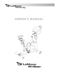
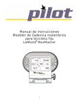
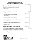
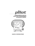
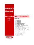
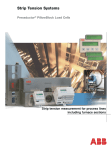
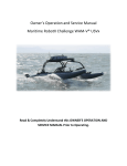
S E R V I C E M A N UA L
For Lemond Exercise Bikes, Models:
15100, 15200, 15300, and15400,
Table of Contents
Exploded Diagrams . . . . . . . . . . . . . . . . . . . . . . . . . . . . . . . . . . . . . . . . . . . . . . . . . . . . . . . . . . . . . . . . . . . . . . . . . . . . . . . . 2
Tool List . . . . . . . . . . . . . . . . . . . . . . . . . . . . . . . . . . . . . . . . . . . . . . . . . . . . . . . . . . . . . . . . . . . . . . . . . . . . . . . . . . . . . . . . . . 10
Installation Check List . . . . . . . . . . . . . . . . . . . . . . . . . . . . . . . . . . . . . . . . . . . . . . . . . . . . . . . . . . . . . . . . . . . . . . . . . . . 11
Stabilizer Bars . . . . . . . . . . . . . . . . . . . . . . . . . . . . . . . . . . . . . . . . . . . . . . . . . . . . . . . . . . . . . . . . . . . . . . . . . . . . . . . . . . . . . 11
Pedals . . . . . . . . . . . . . . . . . . . . . . . . . . . . . . . . . . . . . . . . . . . . . . . . . . . . . . . . . . . . . . . . . . . . . . . . . . . . . . . . . . . . . . . . . . . . 11
Handlebar . . . . . . . . . . . . . . . . . . . . . . . . . . . . . . . . . . . . . . . . . . . . . . . . . . . . . . . . . . . . . . . . . . . . . . . . . . . . . . . . . . . . . . . . 11
Seat Slider . . . . . . . . . . . . . . . . . . . . . . . . . . . . . . . . . . . . . . . . . . . . . . . . . . . . . . . . . . . . . . . . . . . . . . . . . . . . . . . . . . . . . . . . 11
Water Bottle Holder . . . . . . . . . . . . . . . . . . . . . . . . . . . . . . . . . . . . . . . . . . . . . . . . . . . . . . . . . . . . . . . . . . . . . . . . . . . . . . . 11
Maintenance Schedule . . . . . . . . . . . . . . . . . . . . . . . . . . . . . . . . . . . . . . . . . . . . . . . . . . . . . . . . . . . . . . . . . . . . . . . . . . . 12
Troubleshooting . . . . . . . . . . . . . . . . . . . . . . . . . . . . . . . . . . . . . . . . . . . . . . . . . . . . . . . . . . . . . . . . . . . . . . . . . . . . . . . . . . . 13
Disassembly / Adjustment / Assembly . . . . . . . . . . . . . . . . . . . . . . . . . . . . . . . . . . . . . . . . . . . . . . . . . . . . . . . . . . . 15
Handlebar . . . . . . . . . . . . . . . . . . . . . . . . . . . . . . . . . . . . . . . . . . . . . . . . . . . . . . . . . . . . . . . . . . . . . . . . . . . . . . . . . . . . . . . . 15
Pedals . . . . . . . . . . . . . . . . . . . . . . . . . . . . . . . . . . . . . . . . . . . . . . . . . . . . . . . . . . . . . . . . . . . . . . . . . . . . . . . . . . . . . . . . . . . . 16
Crank Arms . . . . . . . . . . . . . . . . . . . . . . . . . . . . . . . . . . . . . . . . . . . . . . . . . . . . . . . . . . . . . . . . . . . . . . . . . . . . . . . . . . . . . . . 17
Belt Cover . . . . . . . . . . . . . . . . . . . . . . . . . . . . . . . . . . . . . . . . . . . . . . . . . . . . . . . . . . . . . . . . . . . . . . . . . . . . . . . . . . . . . . . . . 18
Drive Belt . . . . . . . . . . . . . . . . . . . . . . . . . . . . . . . . . . . . . . . . . . . . . . . . . . . . . . . . . . . . . . . . . . . . . . . . . . . . . . . . . . . . . . . . . 19
Drive Belt Tension . . . . . . . . . . . . . . . . . . . . . . . . . . . . . . . . . . . . . . . . . . . . . . . . . . . . . . . . . . . . . . . . . . . . . . . . . . . . . . . . . . . . . . . . . 20
Bottom Bracket . . . . . . . . . . . . . . . . . . . . . . . . . . . . . . . . . . . . . . . . . . . . . . . . . . . . . . . . . . . . . . . . . . . . . . . . . . . . . . . . . . . . 21
Flywheel . . . . . . . . . . . . . . . . . . . . . . . . . . . . . . . . . . . . . . . . . . . . . . . . . . . . . . . . . . . . . . . . . . . . . . . . . . . . . . . . . . . . . . . . . . 22
Pillow Block . . . . . . . . . . . . . . . . . . . . . . . . . . . . . . . . . . . . . . . . . . . . . . . . . . . . . . . . . . . . . . . . . . . . . . . . . . . . . . . . . . . . . . . . . . . . . . . . 23
Brake Assembly . . . . . . . . . . . . . . . . . . . . . . . . . . . . . . . . . . . . . . . . . . . . . . . . . . . . . . . . . . . . . . . . . . . . . . . . . . . . . . . . . . . 24
Fender . . . . . . . . . . . . . . . . . . . . . . . . . . . . . . . . . . . . . . . . . . . . . . . . . . . . . . . . . . . . . . . . . . . . . . . . . . . . . . . . . . . . . . . . . . . 25
Brake Pad . . . . . . . . . . . . . . . . . . . . . . . . . . . . . . . . . . . . . . . . . . . . . . . . . . . . . . . . . . . . . . . . . . . . . . . . . . . . . . . . . . . . . . . . . . . . . . . . . 26
Adjustment Handles . . . . . . . . . . . . . . . . . . . . . . . . . . . . . . . . . . . . . . . . . . . . . . . . . . . . . . . . . . . . . . . . . . . . . . . . . . . . . . . 27
Pg. 1
Pg. 2
Post Handle
Pin
Post Handle
Indicator
Seat Post Bearing
Sleeve Retainer
Casting Cap
Seat Post Weldment
Post Plug
Assembly
Screw, Socket,
M6 x 65
& M6 Flat Washer
Seat Post Assembly
Dipped Handle
Post Plunger, ED
Post Plunger Fuse
Post Handle Limiter
Post Plunger Bearing
Screw, Dome, M4 x 10 (x2)
Lock Washer, M5
Screw, Dome, M5 x 10
Adjustment Handle, Black
Brass Washer
Seat Slider
Seat with Clamp
Exploded Diagrams
Figure 1.
RevMaster Service Manual
Figure 2.
Pg. 3
Dipped Handle
Post Plug
Assembly
Post Handle
Indicator
Screw, Socket,
M6 x 65
& M6 Flat Washer
HB Post Assy
Post Handle Limiter
Post Plunger Fuse
Post Plunger
Post Plunger Bearing
M5 x 10 Screw, Dome
M6 Lock Washer
Track End Cap (x2)
Screw, Socket M4 x 10 (x4)
Post Handle Pin
HB Post Bearing
Sleeve Retainer
Screw, Dome, M4 x 10 (x2)
Casting Cap
Handlebar Post Weldment
Handlebar Post Bumpstop
M5 x 10 Screw, Dome (x2)
Figure 3.
Pg. 4
RevMaster Service Manual
Left Pedal
Left Crank
Stabilizer End Cap (x2)
Frame Bolt Washer, M8 (x2)
Left Side/Rear Stabilizer
Crank Bolt
Right Pillowblock
Screw, Dome, M4 x 15 (x3)
Screw, Flat Head, M5 x 10
Left X-Cap
Brake Cover
Adjustable Foot (x2)
Rear Stabilizer
Screw, Dome, M8 x 15 (x6)
Stretch Pad Cover
Star Washer, M8 (x2)
X-Cap Gasket, #2
Screw, Flat Head, M4 x 8
Magnet Access Cover
X-Cap Gasket, #3
X-Cap Gasket, #1
Figure 4.
Pg. 5
Frame Bolt Washer, M8 (x2)
Star Washer, M8 (x2)
Adjustable Foot (x2)
Stabilizer End Cap (x2)
Dome Head Screw, M8 x 15 (x4)
Socket Head Screw,
M6 x 15 (x4)
Label, RevMaster Ellipse
Outside Belt Cover
Inside Belt Cover
Socket Head Screw,
M6 x 13 (x2)
Right X-Cover Pad, Printed
Flange Nut, M6 (x2)
Assembly,
Transport Wheel (x2)
Socket Head Screw,
M6 x 40 (x2)
Front Stabilizer
Front Stabilizer/Belt
Cover Exploded View
Figure 5.
Pg. 6
RevMaster Service Manual
Flat Head Screw,
M6 x 16 (x3)
Flywheel
(NO FLANGE)
Pillowblock Nut
(WITH FLANGE)
Pillowblock Nut
Screw, Socket,
M6 x 35 (x4)
Flywheel
Hub Assy
Pillowblock Nut,
No Flange (x2)
Flywheel Assembly
Left Pillowblock
Pillowblock Nut,
Flanged (x2)
Figure 6.
Pg. 7
Brake Assembly
Brake Contact
Bearing
Lower
Brake Spring
Brake Rod Nut
Brake
Distance Tube
Upper
Brake Spring
Upper,
Brake Spacer
Brake Frame Nut
Brake Rod
Assembly
Fender Assembly
Fender Spring
Screw, Dome, M4 x 5 (x2)
Formed Brake Pad
Screw, Dome, M5 x 10 (x2)
Brake Pad Adhesive
Fender Weldment
Fender Cover
Female Shoulder Bolt
Male Shoulder Bolt
Fender Spring Bearing
Figure 7.
Pg. 8
RevMaster Service Manual
Drive System
Right Pedal
Screw, Dome, M4 x 15
Magnet
Holder Assembly
Drive Belt
Bottom Bracket
Assembly, 2 piece
Crank Bolt
Crank Pulley Assy
Idler Bearing Assembly
Idler Traveller Post
Screw, Socket,
M6 x 60
Oval Idler Washer
Idler Spacer
Figure 8.
Pg. 9
Adjustment Handle
Handlebar Slider Plug
Handlebar Slider Plunger
Screw, Socket Head,
M4 x 10 (x4)
Handlebar Slider Bearing (x2)
Screw, Socket Head,
M5 x 15 (x2)
Bottle Holder
Back Mount
Handlebar, Overmolded
Bottle Holder
Front Mount
Plastic Water
Bottle Holder
Handlebar Assembly
Screw, Countersunk,
M5 x 10
Tool List
Assembly tools included with bike:
Tool
3-mm Hex key
6 mm Hwx Key
15 mm Open End
Wrench
Where Used
Used for: H2O bottle mounting screw (mounts the cage to the handlebar
clamp), and handlebar track cap
Used for: front and rear stabilizer mounting bolts
Left and Right Pedals
Additional tools required for service:
Tool
Crank Puller
Bottom Bracket
Socket (Shimano®)
Socket / Torque
Wrench
8-mm Hex key
Locktite 242/243
(blue)
Belt Tension Gauge
Metric Hex Key Set
Pg. 10
Where Used
Pull crank arm off spindle after removing the crank arm bolts.
Bottom Bracket
Bottom Bracket Socket
Crank Bolts
To secure Bottom Bracket
Measure drive belt tension
4mm, 5mm
RevMaster Service Manual
Installation Check List
Stabilizer Bars
Check that the mounting screws, four M8 x 20 screws attach the front stabilizer bar to the frame, and
four more attach the rear stabilizer, are properly aligned (not cross threaded) and use the correct
washers. Check that the top mounting screws use an M8 star washer, and that the bottom mounting
screws use a curved washer, with the concave surface facing the stabilizer. Check that the screws are
securely tightened.
Pedals
Check that the pedals are not cross threaded into
the crank arms. The right pedal has a normal thread
pattern (clockwise to tighten, counter-clockwise to
loosen), and left pedal has a reverse thread pattern
(counter-clockwise to tighten, etc.). When installing
the pedals, use your fingers to start the pedal so you
can feel if you are cross threading them into the crank
arms. Use a 15mm box end wrench to tighten the
pedals after you have installed them finger tight.
Left Crank
Left Pedal
Insert
Counter-Clockwise
Handlebar
When the handlebar is installed, the slider plunger (see figure below) may become dislodged. If this
happened during assembly, the adjustment lever alone will not provide a sufficient grip to secure the
handlebar to the mounting track; if threaded up against the mounting track, it could damaging the
Slider Plunger
track.
If the slider plunger is missing, see Handlebar Adjustment and
Assembly below for instructions on replacing the slider plunger
and installing the handlebar.
Seat Slider
Ensure that the large brass washer is installed on the adjutment
handle attaching the seat slider to the seat post. (See Figure 1.)
Apply a small amount of grease to the threads to allow adjustments.
Water Bottle Holder
The water bottle holder is attached with an M5 countersunk screw to the bottle holder front mount. If
the bottle holder is not already attached, remove one of the one of the M5 countersunk screws from
the front mount with a 3mm hex wrench and use it to attach the bottle holder to the bracket.
Pg. 11
Maintenance Schedule
PART
RECOMMENDED ACTION
1 Pedals
FREQUENCY
CLEANER
LUBRICANT
Ensure that the pedals are tight Before each use N/A
in crank arms; that all screws on
pedals are tight; and that the
pedal straps are not frayed
N/A
Frame
Wipe down
Daily
Soap & water; or, diluted non-abrasive
cleaning solution
N/A
Flywheel
Wipe down
Weekly
WD-40® spray.
Spray on rag &
apply light coat to
sides of flywheel.
N/A
Crank Bolts Inspect for looseness
Weekly
N/A
If loose, remove bolt,
apply Loctite® 242
on bolt threads and
reinstall. Tighten to 48
ft-lbs or 575 in-lbs
Brake Pad
Inspect for excessive wear or a
dry leather brake pad
Weekly
N/A
2 Use 3-IN-One® oil or
Belt
Inspect for correct tension;
replace cracked, frayed, or otherwise non-uniform belt
Monthly
N/A
N/A
Bottom
Bracket
Inspect for side-to-side play in
spindle, and a grinding feeling
in crank area when pedaling.
If necessary, replace bottom
bracket.
Monthly
N/A
N/A
10W oil *Do not use
silicone-based lubricants
)
1. We do not recommend you attempt to service the internal parts of the pedals. If they are found to be
worn internally, we recommend replacing the pedal.
2. Use of lubricants or cleaning solutions other than those so specified will result in diminished performance and a shorter life span for that part.
Pg. 12
RevMaster Service Manual
Trouble Shooting
SYMPTOM: Seat or handlebar post move after locked into position.
1.
Locate smaller 3mm hex bolt at pivot point of cam handle and loosen 1 turn.
2.
Disengage 6mm hex bolt on other side from indicator plate and rotate one notch towards (+) sign.
3.
Tighten smaller 3mm hex bolt.
4.
Test post and repeat process if needed until post no longer moves.
SYMPTOM: Clicking noise with each pedal revolution.
1.
Check shoelaces to make sure the aglet is not tapping the bike as the pedals turn.
2.
Assure pedal straps are tight and that no excess strap on inner part of pedal is catching on the crank
arm as it turns.
3.
Assure that pedals are tight on crank arms.
SYMPTOM: Clicking noise when flywheel rotates.
1.
Check edge of flywheel that brake pad rubs against for small burrs.
2.
If burr is present gently remove while being careful not to damage flywheel surface.
3.
If symptom persists check for noisy flywheel bearings.
4.
If flywheel bearings are noisy or rough have authorized service technician replace flywheel hub assembly.
SYMPTOM: Drive belt is slipping.
1.
Remove belt cover.
Note: Use caution around belt when cover is removed.
2.
Loosen idler with 8mm hex and tighten tensioner bolt 2-3 turns with 5mm hex wrench.
3.
Tighten idler and test belt.
4.
If belt still slips repeat process until belt no longer slips.
5.
Reinstall belt cover.
SYMPTOM: Knocking noise or play felt in pedals/cranks.
1.
Make sure pedals are tight on crank arms.
Note: Left pedal is reverse threaded.
2.
Make sure crank bolts are tight. If loose, apply blue Loctite 242 to threads and tighten crank bolts
with 8mm hex wrench.
3.
If problem persists check the bottom bracket bearing cups for looseness. Tighten if necessary with
a bottom bracket tool and use blue Loctite 242 on threads.
4.
If knocking noise still persists contact authorized service technician for replacement of bottom
bracket bearings.
Pg. 13
SYMPTOM: Inconsistent resistance or noisy brake pad.
1.
Remove fender assembly and make sure brake pad is clean.
2.
Apply brake pad oil (or 3-In-One oil) to surface of brake pad.
3.
Let oil soak into pad and reapply if needed until brake pad is thoroughly saturated.
4.
Reinstall fender assembly.
SYMPTOM: Rocking or movement from RevMaster while in use.
1.
Using a 6mm hex wrench, check the attachment bolts on the front and rear stabilizers and make
sure they are tight (4 bolts on each stabilizer).
Note: You will have to remove the stretch pad to check the rear stabilizer mounting bolts.
2.
Assure the bike is level by checking the leveling feet on the bottom of the front and rear stabilizers.
Pg. 14
RevMaster Service Manual
Assembly/Disassembly/Adjustment
HANDLEBAR
When the handlebar is first installed on the bike there is a slider plunger (or “pill”) at the end of the adjustment handle that is held in place by shipping material. The material is pushed out of the way when
the handlebar assembly is slid onto the track of the handlebar post. The adjustment handle pushes the
slider plunger against the track to secure the handlebar assembly in place.
Installation
Loosen the adjustment handle on the handlebar assembly. Slide the assembly onto the track of the
handlebar post and tighten the adjustment handle. Then install the handlebar track cap onto the end of
the track with two (2) M4 X 10mm screws.
Removal
To remove the handlebar assembly, first remove the track end cap. Loosen the adjustment handle and
slide the handlebar off the end of the track. Take care not to dislodge the slider plunger at the end of the
adjustment handle.
Pg. 15
PEDALS
Use a 15mm open end wrench or pedal wrench to install and remove pedals.
Installation
One pedal will be labeled (L) for left and the other pedal (R) for right. Also note the left pedal is reverse
threaded. Carefully thread the left pedal into the left crank arm by turning counterclockwise and tighten
by hand being careful not to cross the threads. With the same mindfulness tighten the right pedal into
the right crank arm. Then firmly tighten down both pedals with the wrench.
Removal
Unscrew the left pedal by turning it clockwise with a wrench. Unscrew the right pedal by turning it
counterclockwise.
Pg. 16
RevMaster Service Manual
CRANK ARMS
Use a 8mm hex wrench to install/remove crank bolts & use a Park CCP-2 or similar crank arm puller to
remove crank arms.
Removal
Left crank - Unscrew the crank bolt with 8mm hex wrench. Thread crank puller into the threads of crank
arm being careful not to cross the threads and tighten by hand. Turn the handle of crank puller clockwise until crank arm is removed.
Right crank - Remove the belt cover and drive belt. Unscrew the crank bolt with 8mm hex wrench and
follow same directions as Left crank.
Installation
Lubricate the taper of the spindle with a small amount of multi-purpose grease. Slide the crank arms
onto the spindle assuring they are rotated 180 degrees from each other. Screw in crank bolts (new
bolts are factory coated with Loctite or if needed use medium 242 strength Loctite) and firmly tighten.
Recheck periodically.
Pg. 17
bELT COVER
Use a 3mm hex wrench & 5mm hex wrench to install/remove belt cover.
Removal
Remove the three 3mm screws from left side (non-drive side) of the bike. Rotate the right crank arm to
the 10 o’clock position. Remove the four 5mm screws from the right side (drive side) and remove belt
cover. Please note: Always use caution around drive belt when cover is removed.
Installation
Rotate the right crank arm to the 10 o’clock position. Pass the right crank arm through hole of belt cover
and line up screw holes of belt cover with threaded holes in frame of bike. Insert and gently snug down
each of the 5mm screws from the right side and each of the 3mm screws from the left side.
Pg. 18
RevMaster Service Manual
DRIVE BELT/drive belt tension
Use a 5mm hex wrench (long T-handle works best) & 8mm hex wrench to remove/install or adjust drive
belt.
Please use caution around drive belt when installing, removing or adjusting belt.
Removal
Remove belt cover. Loosen the shoulder bolt of idler bearing assembly ¼ turn with a 8mm hex wrench.
Loosen the tension screw (M6 x 60) with a 5mm hex wrench until the idler bearings can be pushed to the
top of the slot in frame and bearings are loose enough to allow you to remove the drive belt from the
pulleys.
IInstallation
Wrap the drive belt around the front flywheel pulley. Pass the top of the belt under the tensioner bearings (tensioner bearing assembly should be loose and able to move freely in slot) and over the top of the
rear crank pulley. Continue feeding the belt onto the crank pulley while working your way counterclockwise. If the belt is too tight near the bottom to slide over the pulley, keep tension on the belt and slowly
rotate the right crank arm counterclockwise to walk the rest of the drive belt onto the pulley. Check to
make sure the belt is centered on both pulleys and the upper portion of the belt is under the tensioner
bearings. Also check that the idler spacer located directly behind the idler bearings is still sitting on the
shoulder bolt with the bearings.
Pg. 19
To tension the belt, tighten the tension screw (with 5mm hex wrench) so the idler bearings begin to put
downward pressure on the belt. Test the belt tension intermittently while tightening the tension screw
by getting on the bike and standing up on the pedals. With the cranks parallel to the floor slowly rock
back and then give a quick downward thrust with your forward foot. If the belt slips, continue to tighten,
and repeat the process of testing and tightening until no slippage is detected. Also note that a heavier
person or one who uses very heavy resistance may need more tension on the belt. When the proper belt
tension is reached firmly tighten the shoulder bolt. If the tensioner bearings sit at an angle and are not
perpendicular to the frame after tightening, check to make sure the idler spacer that sits directly behind
the idler bearings is still sitting on the shoulder bolt with the bearings and has not fallen off. Reinstall
the belt cover.
Pg. 20
RevMaster Service Manual
BOTTOM BRACKET BEARING ASSEMBLY
Use a Park BBT-22 or similar bottom bracket tool & blue medium 242 strength Loctite.
Removal
Remove the belt cover, drive belt and crank arms. Then remove the left bearing cup using the bottom
bracket tool by turning the cup counterclockwise. Loosen the right cup (reverse threaded) by turning
the cup clockwise until you are able to remove the right cup with the remainder of the cartridge assembly from the frame.
Remove Leftside
Remove Rightside
Installation
Clean the bottom bracket threads in the frame. Set the left cup of the bearing assembly aside for now.
Apply a few drops of medium strength Loctite to the right bearing cup and insert the cartridge assembly into the bottom bracket from the right side (drive side). Carefully screw the right cup into the frame
with your hand by turning the cup counterclockwise (right cup is reverse threaded) while being cautious
not to cross the threads. Firmly tighten the right cup with the bottom bracket tool. Apply a few drops
of Loctite to the left bearing cup. Carefully screw the left cup into the frame with your hand by turning
clockwise while again being cautious not to cross the threads, and torque to 175 inch/lbs. If you do not
have a torque wrench, tighten the cup, but stop and twist the spindle with your hand periodically as you
go to assure that the cup is fully threaded into the frame but loose enough to allow the spindle to rotate
freely. If the rotation of the spindle feels rough or clunky loosen the cup and test again. Reinstall the
crank arms, drive belt and belt cover. Allow loctite to dry for 24 Hours before using the unit.
Use Loctite 242
Pg. 21
FLYWHEEL
Use a 5mm hex wrench to remove flywheel assembly & 4mm hex wrench to remove flywheel hub assembly from flywheel. Also use medium 242 strength Loctite.
Removal
Remove belt cover, drive belt and fender assembly and raise handlebar post to a higher position. It
is also helpful to raise the brake rod up and wrap a piece of electrical tape around the brake shaft,
just above the brake nut to prevent the bottom of the rod from getting in the way. Using a 5mm hex
wrench, remove the two pillow block screws (M6 x 35) from right pillow block and the two pillow block
screws (M6 x 35) from the left pillow block. Before removing the flywheel assembly, please note it is
heavy and weights 48lbs. Carefully lift the flywheel so the pillow blocks unseat themselves from the
frame and slowly move the flywheel forward out of the frame. Be careful not to scratch or dent the
surface of the flywheel. If needed, a rag can be put under the flywheel when removing to provide a
softer surface.
Pg. 22
RevMaster Service Manual
Removing and Replacing Hub Assembly in Flywheel
If the flywheel bearings or pulley are damaged a new flywheel hub assembly will need to be installed.
Pull the left pillow block off the bearings after flywheel is removed from bike. Remove the three screws
(M6 x 16) from the left side of the flywheel with a 4mm hex wrench. These screws hold the hub assembly to the flywheel. Once hub assembly is removed apply medium strength Loctite to the three M6 x 16
screws. Insert the new hub assembly in the flywheel and install the three M6 x 16 screws with Loctite.
Firmly tighten screws and place left pillow block back on bearings. Flywheel assembly is now ready to
be installed on the bike.
Installation
Place the pillow block nuts back in the frame. The flanged nuts need to be inserted on the left side and
the nuts with no flange need to be inserted on the right side (Note: These cannot be reversed since a
flanged nut on the right side will rub on the drive belt). Rotate the pillow blocks so the tops of both are
facing up and are parallel with each other (if one or both of the pillow blocks rotates during the install
and is inserted into the cutaway upside down the flywheel will sit cockeyed and/or up too high). Carefully lift the flywheel assembly back into the frame and lower the pillow blocks into the cutaways in
the frame. Once the flywheel sits securely in the frame, apply Loctite to the pillow block screws. Insert
the screws through the pillow blocks, start tightening by hand and then firmly tighten with a 5mm hex
wrench. Reinstall the fender assembly, drive belt and belt
cover. Ride the bike to test.
Pg. 23
BRAKE ASSEMBLY
Use an adjustable crescent wrench to remove/install brake assembly.
Removal
Turn the brake rod counterclockwise to loosen the tension. Loosen the brake frame nut with a crescent
wrench. Make sure the two flat edges of the plastic nut on the very bottom of the rod are facing the
front and rear of the bike. The flat surface of the plastic nut will then line up with the flat surface inside
the tube. Pull up on the brake assembly and remove from the frame.
Installation
Check that the brake rod nut located between the two springs is threaded on the lower portion of the
top set of threads. Line up the flat surface of the brake rod nut with the flat surface of the plastic nut on
the bottom of the brake rod. Insert the brake rod assembly into the frame with the flat surfaces of both
nuts facing the back of the bike so they meet the flat surface inside the tube. Tighten down the brake
frame nut.
Pg. 24
RevMaster Service Manual
FENDER ASSEMBLY
A 5mm hex wrench & 4mm hex wrench will be used simultaneously. Also use medium 242 strength
Loctite.
Removal
Raise the handlebar post to a higher position to get it out of the way. Locate the bolt at the rear of the
fender and remove with 5mm and 4mm hex wrenches. Hold the brake rod up and pull the fender assembly from the bike.
Pg. 25
Brake Pad Removal/Install
Use 3mm hex wrench & brake pad oil (or 3-In-One Multi-purpose oil).
With the fender assembly off the bike use a 3mm hex wrench to remove the two screws that hold the
brake pad to the fender. Remove the pad and scrape away any of the foam padding still stuck to the
fender. Peel off the backing of the foam on the new brake pad to expose the sticky surface of the foam.
Screw the new brake pad onto the fender with the foam side facing the fender and press across the
length of the pad so the foam sticks to the fender. Coat the surface of the brake pad with brake pad oil
and allow it to soak into the pad. Repeat the process 4-5 times or until the pad is saturated with oil (but
not dripping). The fender assembly is now ready to be installed on bike.
Installation
Apply Loctite to the male portion of the bolt that holds the fender to the frame. Lift up on the brake rod
and slide the fender assembly over the top of the flywheel and line the holes in the back of the fender
with the hole in the frame. Insert the female section of the bolt from either side, through the hole in the
fender and into the hole in the frame. Then insert the male portion of the bolt from the other side and
thread the two parts of the bolt into each other. Gently snug the bolt down with hex wrenches but be
careful not to over tighten or the bolt will break. Ride and test bike with resistance.
l
Pg. 26
RevMaster Service Manual
ADJUSTMENT HANDLES (Handlebar/Seat Post Height Adjustment Handles)
Use 6mm hex wrench & 3mm hex wrench to adjust the handles.
Adjustment
Handles need to be unlocked to adjust the tightness of the handle against the post. Lift up on the
handle to unlock and lower the post until it bottoms out. If adjusting the seat post, first remove the
seat with the seat slider from post so the fore/aft adjustment handle is out of the way. Loosen the
screw on right side of bike one turn with 3mm hex wrench. Push in on this screw so the 6mm screw
(Post Handle Pin) on the other side disengages from the teeth in the indicator plate.
To increase the handle pressure on the post, rotate the 6mm screw towards the (+) sign by 1 tooth while
lifting up on the handle. Then push the screw in so it locks into the teeth on the indicator plate and let
go of the handle. Tighten the 3mm screw on the right side of the bike and raise the post up and test.
Repeat the process if more pressure is needed.
To decrease the handle pressure on the post, rotate the 6mm screw towards the (-) sign by 1 tooth while
lifting up on the handle. Then push the screw in so it locks into the teeth on the indicator plate and let
go of the handle. Tighten the 3mm screw on the right side of the bike and raise the post up and test.
Repeat the process if the handle is hard to lock down and less pressure is needed.
Pg. 27
15540 Woodinville-Redmond Road NE
Suite A100
Woodinville, WA 98072 USA
www.LeMondfitness.com
Telephone (+1) 425.482.6773 x 107 or 109
Fax: (+1) 425.482.6724
Email: [email protected]
Document #300137, Rev