1
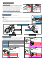
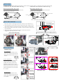
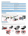
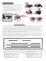
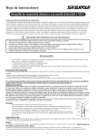
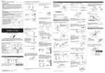
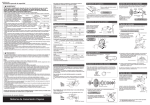
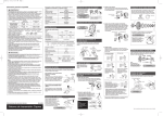
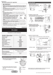
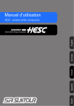
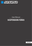
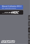
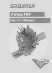
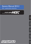
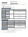
SR SUNTOUR
SERVICE MANUAL
Front drive system
Thank you for choosing SR SUNTOUR products. In order to maximize the shifting performance, please kindly read this instruction sheet carefully before starting to use the SR Suntour drive train.
Key features
Double action front derailleur.
Cable saver system Twist shifter.
PowerFlo Front index shifting design chainwheel.
Front derailleur/shiftlever specifications
Front
Compatible ring
FD-XCR706
FD-XCR704/504
FD-XCR502
FD-XCR508
FD-CR318
FD-XCC312
FD-CR328
FD-XCC322
FD-XCC202
FD-CR208
FD-XCC102
FD-XR/TP17
FD-XR/TP05
46/32/22T
44/32/22T
42/32/22T
Compatible speed
Compatible shift lever
DSM-XCR61/71-DR, DSC-NCX60/70-DR, SL-DURO27E-L3
27S
DSM-XCR61/71-DR, DSC-NCX60/70-DR, SL-DURO27E-L3
SRAM, Shimano
48/38/28T
42/32/22T
48/38/28T
DSM-XCR51-DR, DSC-NCX50-DR, TS-NCX/CR500-L3,
SRAM, Shimano
42/32/22T
48/38/28T
24S
42/34/24T
SRAM, Shimano
48/38/28T
Chainwheel specifications
Chainwheel
X-OFF series
Durolux series
XCR series
DURO series
XCC300 series
NCX series
CR series
NEX series
XCC150 / XR series
XCC100 series
Ring combination
32/22T
46/32/22T , 44/32/22T , 32/22T
46/32/22T , 44/32/22T
44/32/22T, 32/22T
48/38/28T , 44/32/22T , 42/32/22T
44/32/22T , 42/32/22T
Compatible BB
BB-X-OFF
OCTALINK (BB-DUROLUX-113) or ISIS
ISIS (BB-XCR-113) or OCTALINK or Square MM110
ISIS (BB-XCR) or Square
Square (MM110)
Square (LL113)
48/38/28T
42/34/24T
48/38/28T
Square (122.5mm)
Chainwheel installation
Using the 8mm Allen wrench, install the chainwheel onto the bottom bracket axle. For such chainwheel
models as NEX, XCC150/100 and XR series, please use the fixing bolts furnished with your bottom brackets.
Suggested tightening torque: Nut type: 45 - 55Nm (450- 550kgf/cm)
Bolt type: 35- 45Nm (350- 450kgf/cm)
Chainline tolerance is ±1.5mm.
Note: Above torque values apply in case of no grease on the B.B. axle taper.
Front derailleur installation
Level
Front derailleur position
With the outer cage directly over and parallel to the outer chainring, be sure to adjust the clearance between the level section of
the outer cage and outer chainring to be 1-3mm as shown [A].
For easier installation, first position the front derailleur on the
smallest chainring temporarily, so that the clearance between the
outer cage and outer chainring is about 1mm as shown [B].
B
A
NOTE (all Front derailleurs except for FD-XR/TP series)
Dual diameter compatible clamp design allows you to choose
Outer cage
Outer ring
either 31.8 or 34.9mm seat tube. Before you install the front derailleur, check the seat tube diameter to have correct clamp. If it is 34.9mm, then remove the plastic adaptor from the clamp band.
Control installation
Insert the control to the handle bar as described below.
Note
*DSC type controls
When using DSC type controls, please be sure to use the grip length that is more than 62mm for
proper grip.
*TS type control
Before installing grips, be sure to put the 0.5mm slide washers between the controls and grips.
After installing grips, adjust the position of the controls, making sure not to push them too hard
against grips. Otherwise it may affect the shifting function and make the operation heavier.
Do not push too hard toward
the movable grip
5mm Allen
wrench
Tightening torque
7 - 9 Nm
Suggested tightening torque
5Nm
3mm Allen wrench
5mm Allen wrench
1.9 Nm
DSM & DSC types
SL-DURO type
Handlebar dimension
When using the SR SUNTOUR Control, it is necessary to maintain
straight section „L“ at the handlebar ends as shown below. Please
select handlebars according to the dimensions shown here.
SL-DURO type
DSM type
DSC type
TS type
DSC-TYPE
Straight section on „L“
13mm + Brake bracket size (A) + Grip length
Brake bracket size (A) + 54mm + Grip length
Brake bracket size (A) + 88mm + B (should be
more than 62mm)
72mm + Grip length
A
Grip length
54mm
L
DSM-TYPE
SL-DURO TYPE
A
13mm
Grip length
L
A
Grip length 62+
88mm
L
Chain length
In order to get maximum shifting performance, please follow the points below to determine the proper chain length.
Chainwheel: 42T, 44T, 46T or 48T outer ring
Chainwheel: 42T, 44T, 46T or 48T outer ring
Rear largest sprocket: 30T or 32T
Add 4 links after putting the chain on the front
and rear largest sprockets.
Rear largest sprocket: 34T
Add 2 links after putting the chain on the front
and rear largest sprockets.
Front chainwheel
Chain
Cassette
Add 4 links (with chain tightened)
Add 2 links (with chain tightened)
Inner cable connection
1. Set the control to the stopper position as shown in the indicator [1].
2. This Dual-pull system allows to have down-pull cable routing or toppull cable routing. So choose the proper cable routing as shown here.
3. After taking up the initial slack of cable, connect the inner cable to the
front derailleur.
4. Tighten the inner cable fixing bolt with a 5mm Allen wrench.
Suggested tightening torque: 5-7 Nm.
SL-DURO type
3
1
Front derailleur control at stopper positon
Inner cable fixing bolt
Down-pull cable connection
Top-pull cable connection
Stopper
position
DSM/DSC types
1
Index adjustment
3
Outer casing adjustment
barrel
Low „L“
adjustment
1. Shifting range
Low adjustment
Turn the Low adjustment screw
so that the clearance between the
Inner plate and the chain is at 0.51.0mm.
B
A
Center adjustment
Set the chain onto the largest rear
sprocket and center chainring.
Adjust the position of the front
derailleur, using the outer casing
adjustment barrel on the control, so
that the clerance between the Inner
plate and the chain to be at around
0.5-1.0mm.
Around
0,5-1,0mm
clearance
Inner
plate
A
B
Chain
Around
0,5-1,0mm
clearance
Inner plate
Chain
B
A
Top „H“
adjustment
Top adjustment
Turn the Top adjustment screw
so that the clearance between the
Outer plate and the chain to be at
0.5-1.0mm.
B
A
Outer plate
Around
0,5-1,0mm
clearance
DSM/DSC types
SL-DURO type
2. Troubleshooting of the adjustment
10. After completing the above steps, move the shift lever to see the shifting performance.
If shifting from the smallest chainring to the center ring is difficult.
Turn the outer casing adjustment barrel on the control counterclockwise (about 1/4 turns).
Turn the top adjustment screw on the front derailleur counterclockwise (about 1/4 turns).
Turn the top adjustment screw on the front derailleur clockwise
(about 1/4 turns).
Turn the outer casing adjustment barrel on the control clockwise
(about 1/4 turns).
Turn the low adjustment screw on the front derailleur counterclockwise (about 1/4 turns).
Turn the low adjustment screw on the front derailleur clockwise
(about 1/4 turns).
The level section of the outer plate should be directly above and
parallel to the largest chainring.
If shifting from the center chainring to the outer ring is difficult.
If the chain falls to the crank side.
If shifting from the outer chainring to the center ring is difficult.
If shifting from the center chainring to the smallest ring is difficult.
If the chain falls to the bottom bracket side.
When the chain is on the center chainring, if there is interference
between the chain and front derailleur outer plate when shifted to
the smallest sprocket and interference between the chain and front
derailleur inner plate when shifted to the largest sprocket.
Control operation
When operating the controls, always be sure to turn the crank arm at the same time.
Rotate the movable grip to the (A) direction to shift from smaller chainring to a larger ring and to the (B) direction to shift
from a larger chainring to a smaller ring.
%
DSM/DSC types
6/'852W\SH
A
A
A
TS type
B
B
Replacing the inner cable
1. Return the control to stopper position.
2. Open the indicator window by a finger or a screw driver (-). (For TS type: Loosen the cap screw counter-clockwise with a
2.5mm allen wrench.)
3. Push out the old inner cable, and install the new inner cable. At this time, check to see if the control is at the stopper position.
4. Close the indicator window. (For TS type: Tighten the cap screw clockwise with a 2.5mm allen wrench.
Suggested tightening torque is 0.05Nm. Then close the cable replacement port.)
1st step: Return the lever to the
2nd step: Open the
indicator window.
stopper position
3
3rd step: Take out the
cable nipple.
4
2
1
3
DSM/DSC types
CABLE NIPPLE
5
NIPPLE STOPPER
4th step: Push
down the nipple
stopper and take
out the old cable.
Insert the new
cable.
SLOT
6
7
Replacing the inner cable
6/'852W\SH
1. Return the control to stopper position.
2. Open the indicator window by a finger or a screw driver (-).
(For TS type: Loosen the cap screw counter-clockwise with a
2.5mm allen wrench.)
3. Push out the old inner cable, and install the new inner cable.
At this time, check to see if the control is at the stopper position.
4. Close the indicator window. (For TS type: Tighten the cap
screw clockwise with a 2.5mm allen wrench.
Suggested tightening torque is 0.05Nm. Then close the cable
replacement port.)
3
1
3
1
1st step: Return the lever to the
3rd step: Open the indicator window,
stopper position
4
2
Stopper position
CABLE NIPPLE
2nd step: Open the indicator window, using a flat screwdriver.
4th step: Take out the cable nipple.
NIPPLE STOPPER
5
5th step: Push down the nipple
stopper, in order to release the cable nipple - take out the old cable.
6
7
2.5 Allen key
SLOT
LIMITED WARRANTY
SR SUNTOUR warrants the drive train to be free from defects in materials and workmanship under normal use for a period of
two years from the date of purchase. In no event shall this limited warranty apply to any defect of the drive train caused by: improper installation, disassembly, reassembly, intentional breakage or damage, alterations or modifications to the drive train by the
user or other party or any unreasonable use or abuse of the product or any use for which this product was not intended.
The obligation of this limited warranty shall be limited to repairing or replacing the drive train or any part for which there is a
defect in materials or workmanship during the two years following the date of purchase. To validate this limited warranty the
purchaser must submit this warranty card to SR SUNTOUR within 30 days after purchase of the drive train. Any alteration of, or
tampering with the warranty card automatically terminates this limited warranty.
SR SUNTOUR makes no express or implied warranties of fitness or merchatability of any kind, except as set forth above. SR
SUNTOUR’s liability hereunder is expressly limited to repair or replacement of the product. Under no circumstances will SR
SUNTOUR be liable for incidental or consequential damages. Some jurisdictions do not allow the exclusion or limitation of liability of incidental or consequential damages, so the above exclusion may not apply to you. This warranty gives you specific rights
and you may have other rights which vary from jurisdiction to jurisdiction.
Drive Train Warranty Card:
Date of purchase:
Model name
Term of limited warranty: Two years from the date of purchase
Dealer
Name:
Phone#:
Name:
Phone#:
Address:
Purchaser
Address:
This warranty is void without proof of purchase.
SR SUNTOUR INC.
No.7 Hsing Yeh Road, Fu Hsing Industrial Zone.Changhua.50606. Taiwan, R.O.C.
Tel:00886-4-7695115 / Fax: 00886-4-769 4028 / E-mail: [email protected]
SR SUNTOUR USA
P.O. Box 61988 Vancouver WA 98666
Tel: 1- 360 737 6450 / Fax: 1 360 737 6452 /
E-mail: [email protected]
SR SUNTOUR EUROPE S.A.
Chaussee de Tervueren,43,1410 Waterloo. Belgium
Tel: 0032-2-3544676 / Fax: 0032-2-354 7835 /
E-mail: [email protected]
SR SUNTOUR INC.
Specifications are subject to change without notice.
Printed in TAIWAN.