1
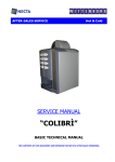
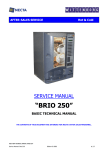
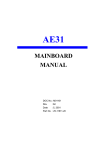
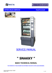
AFTER-SALES SERVICE
Hot & Cold
SERVICE MANUAL
“ Kikko ”
BASIC TECHNICAL MANUAL
THE CONTENTS OF THIS DOCUMENT ARE INTENDED FOR NECTA’S AFTER SALES PERSONNEL
NECTA SPA
TECHNICAL MANUAL“ Kikko “
Manual Kikko
1 / 28
TABLE OF CONTENTS
1
2
3
4
5
6
7
8
9
10
11
12
13
14
15
16
Pages 3-4-5-6
Pages 7 - 12
Pages 13-14
Page 15
Page 15
Page 16
Pages 16-17
Page 18
Page 19
Page 20
Page 21
Page 22-23
Page 24
Page 25
Page 26
Pages 27-28
Layout
Electrical systems, connections and configuration
Air-break / Boilers
Pumps and by-pass
Coffee brewer unit
Sugar and stirrer release unit
Cup dispenser assembly
Mobile spouts assembly
Doser devices and powder product containers
Mixer unit
Powder and water dose tables
Trouble-shooting
Wiring diagrams
HACCP directive (Use instructions)
Daily cleaning and hygiene
Weekly / monthly cleaning and hygiene
NOTE
The above systems and functional units are specific to this machine.
All functional units installed but not listed in this document, are also used in other machines in the same range; therefore
they will be described in a separate manual for machines belonging to the same range, where all base functional units will
be described more in detail
Lift-up top
panel
Coffee bean hopper
instant product
6
containers
Sugar container
Compartment for CPU
/ display boards and
payment systems
8
Brewer unit with
grinder and doser unit
1
CPU Board
4
Cup Dispenser
unit
Mixer
Dispensing
spout
assembly
2
Dispensing
compartment
Liquid waster
container
Dispensing
compartment slider
Coin box
VIEW WITH DOOR OPEN
NECTA SPA
TECHNICAL MANUAL“ Kikko “
Manual Kikko
2 / 28
1 – HYDRAULIC LAYOUT
4
14
5
6
3
9
2
17
7
15
8
13
1
16
10
11
12
Hydraulic layout “ESPRESSO” version
REF.
DESCRIPTION
REF
DESCRIPTION
REF
DESCRIPTION
1
Water inlet solenoid valve
7
By pass
13
Overflow tube
2
Volumetric counter
8
Vibration pump
14
Air-break micro-switch
3
Water filter
9
Coffee unit
15
Instant coffee mixer
4
Air - break
10
Dispensing spout assembly
16
Milk/Chocolate mixer
5
Solenoid valve units
11
Float micro-switch
17
Tea mixer
6
Pressure boiler
12
Liquid waste container
In the espresso version only one boiler is used (with by-pass set to 12 bar) that is also used for dispensing
instant products.
NECTA SPA
TECHNICAL MANUAL“ Kikko “
Manual Kikko
3 / 28
Hydraulic layout “INSTANT” version
6
4
2
3
12
5
10
11
1
7
13
9
8
INSTANT VERSION COMPONENTS
REF.
1
2
3
4
5
6
DESCRIPTION
Water inlet solenoid valve
Instant Boiler
Instant solenoid valve
Anti-boiling thermostat
Overflow tube
Air-break level microswitch
REF.
7
9
10
11
12
13
DESCRIPTION
Waste level microswitch
Dispensing spouts
Coffee mixer
Milk/Chocolate mixer
Tea mixer
Overflow tray
In the Instant version an open-top boiler, operating at the atmospheric pressure.
NECTA SPA
TECHNICAL MANUAL“ Kikko “
Manual Kikko
4 / 28
BASE ESPRESSO VERSION LAYOUT
BASE VERSION - ITALY
PRODUCT BUTTONS AND LABEL DIAGRAM
ESPRESSO VERSION - ITALY
NECTA SPA
TECHNICAL MANUAL“ Kikko “
Manual Kikko
5 / 28
BASE INSTANT VERSION LAYOUT
BASE VERSION - ITALY
PRODUCT BUTTONS AND LABEL DIAGRAM
INSTANT VERSION - ITALY
NECTA SPA
TECHNICAL MANUAL“ Kikko “
Manual Kikko
6 / 28
2 - ELECTRICAL SYSTEMS - CONNECTIONS - CONFIGURATIONS
The machine is designed to operate under a single-phase voltage of 230 V AC (+5-10V)
It is protected with a main 15 A fuse on both phases.
With regard to the transformer:
Power supply cable connection diagram
The primary winding is protected with a 125 mA fuse
The secondary winding is protected with a 1.25 mA fuse
The machine is fitted with a door opening safety switch.
The power cable can be supplied as a standard feature and chosen among the following types:
Lift-up cover
HO5 RN – F copper with a 3 x 1.5 mm2 section
HO5 V V – F ,,
,,
,,
,,
HO5 V V – F ,,
,,
,,
,,
Fitted with a fixed SCHUKO plug.
NB **: it is possible that for some specific markets a cable with a
specific plug is fitted at the factory, in accordance with the
Cable
regulations in force in those countries.
clamp
In the event of replacement cables of exactly the same
characteristics must be used.
Cable from
Since the “Kikko” vending machine is approved by an electrical
the mains
safety certification institute (IMQ), replacements with non-original
components are not permitted.
Otherwise the electrical safety certificate and the warranty will be
void.
2.1 - Boards Connections
View of power supply unit and actuation board compartment (without casing)
230 V / 50 Hz
auxiliary socket
Transformer
Connection
cable
15 A Grid
fuses
Secondary fuses
Earth wire connection
point
Radio interference
suppressor
Actuation relays
(see list)
(
Actuation board
Actuation Connector
NECTA SPA
TECHNICAL MANUAL“ Kikko “
Manual Kikko
7 / 28
CPU Board connection diagram
J7 connection to connector
J4 on actuation board SM
J10
connection to
display board
(LCD)
CPU Board
SUC
Free vend control
buttons,
Cleaning button
and Jug facilities
RS 232 port for
data storing
and reading
J15 Connector
for 24 V 2 A
power supply
J14
MDB Connector
J11+ J3 connector to selection
push-button board
NOTE: The RS232 serial board for communication protocols can be supplied on request.
SERIAL payment systems can be connected to such board, using the following protocols:
executive – MDB - BDV
Code
Description
SM
Actuation and control board
LCD display card
Espresso temperature control probe
Instant temperature control probe
Volumetric counter
Printer or data reading device port (only if the
relevant optional board is installed)
Push-button board
Cup sensor switch
Water sensor (level) switch
Liquid waste overflow switch
Cup release motor cam
Spout shift motor
Spout position switch
LCD
NTC
NTCS
CV
RS 232
SP
IVB
IVA
IPF
CMSB
MSU
MPU
NECTA SPA
TECHNICAL MANUAL“ Kikko “
Manual Kikko
8 / 28
ESPRESSO VERSION WIRING DIAGRAM
To connector
J15 on CPU
Power
supply
cable
from the
mains
Cup sensor
(optional) SZ
Actuation board
J4
To the CPU
board (SUC)
SM1
SM 2
Actuation board
SM1
Actuation board extension
SM2 (in some versions)
UPS Cold unit
Optional
INSTANT VERSION WIRING DIAGRAM
To connector
J15 on CPU
Power
supply
cable
from the
mains
Cup sensor
(optional) SZ
Actuation board
Actuation board
SM1
J4
To the CPU
board (SUC)
)
SM1
Actuation board extension
SM2 (in some versions)
UPS Cold unit
Optional
NECTA SPA
TECHNICAL MANUAL“ Kikko “
Manual Kikko
9 / 28
The actuation board controls all 230 V AC power users by
means of relays. It also processes the signals from the cams
and the microswitches from the various users and controls the
boiler board. The board is powered with 24 V DC by means of
a power supply unit located in the panel.
The control SW is loaded directly on the microprocessor.
The GREEN LED (2) blinks during normal operation of the
board..
The YELLOW LED(6) indicates the presence of 12 V DC
The RED LED (3) glows during the card reset.
The RED LED ( 10) indicates the operating status of the
Espresso boiler heating element.
ACTUATION BOARD
(Positioning, logics and actuation diagrams)
VIEW OF ACTUATION BOARD AND
POWER SUPPLY UNIT COMPARTMENT
22
21
23
20
24
25
26
REF.
1
2
3
4
5
6
7
8
9
10
11
12
13
14
15
16
17
18
19
20
21
22
23
24
25
26
NECTA SPA
DESCRIPTION
CONNECTOR FOR INPUT SIGNALS
GREEN LED
RED LED
CONNECTOR NOT USED
CONNECTOR FOR BOARD PROGRAMMING
YELLOW LED
CONNECTOR FOR BOARD POWER SUPPLY
CONNECTOR NOT USED
CONNECTOR FOR PROBE AND BOILER CONTROL
RED LED FOR BOILER OPERATION
Red LED - BOARD RESET
CONNECTOR TO EXPANSION BOARD
230 V AC POWER USERS
230 V AC POWER USERS
230 V AC POWER USERS
230 V AC POWER USERS
CONNECTOR NOT USED
CAN BUS CONNECTOR**
CONNECTOR NOT USED
TRANSFORMER FUSES
POWER SUPPLY TRANSFORMER
PERMANENTLY LIVE 230 V AC SOCKET
NETWORK FUSES
LED
BOILER CONTROL BOARD
ACTUATION RELAY SERIES
Actuation board layout
CAN BUS **
Connector for multiple machine installation with
GSM protocol
TECHNICAL MANUAL“ Kikko “
Manual Kikko
10 / 28
EXPLODED VIEW OF POWER SUPPLY UNIT AND WIRING COMPARTMENT
Reference to relay code and actuations - Espresso / Instant version
Espresso Configuration
(see previous page references)
K1
K2
K3
K4
K5
K6
K7
K8
K9
K 10
K 11
K 12
K 13
K 14
K 15
K 16
K 17
K 18
K 19
K 20
K 21
K 22
K 23
K 24
COFFEE RELEASE MAGNETS
K1
CUP RELEASE RATIOMOTOR
K2
CUP COLUMN SHIFT MOTOR
K3
STIRRER DISPENSING MOTOR
K4
NOT USED
K5
SWITCHING LAMP ON
K6
DISPENSING SPOUT MOVEMENT RATIOMOTOR K 7
COFFEE UNIT RATIOMOTOR
K8
ELECTRIC MIXER MF3
K9
ELECTRIC MIXER MF2
K 10
ELECTRIC MIXER MF1
K 11
SUGAR DOSER DEVICE
K 12
STARTING PUMP
K 13
ELETTROVALVOLA EROG. CAFFE’
K 14
Solenoid Valve EV 1
K 15
SOLENOID VALVE EV 2
K 16
SOLENOID VALVE EV 3
K 17
WATER INLET SOLENOID VALVE
K 18
NOT USED
K 19
GRINDER MOTOR
K 20
DOSER DEVICE MD4
K 21
DOSER DEVICE MD3
K 22
DOSER DEVICE MD4
K 23
DOSER DEVICE MD5
K 24
NECTA SPA
Instant Configuration
(see previous page references)
DOSER DEVICE MD6
CUP RELEASE RATIOMOTOR
CUP COLUMN SHIFT MOTOR
STIRRER DISPENSING MOTOR
STIRRER DISPENSING MOTOR
SWITCHING LAMP ON
DISPENSING SPOUT MOVEMENT RATIOMOTOR
ELECTRIC MIXER MF4
ELECTRIC MIXER MF3
ELECTRIC MIXER MF2
ELECTRIC MIXER MF1
ELECTRIC MIXER MF3
SOLENOID VALVE EV 4
SOLENOID VALVE EV 5
SOLENOID VALVE EV 1
SOLENOID VALVE EV 2
SOLENOID VALVE EV 3
WATER INLET SOLENOID VALVE
ELECTRIC MIXER MF5
DOSER DEVICE MD5
DOSER DEVICE MD4
DOSER DEVICE MD3
DOSER DEVICE MD2
DOSER DEVICE MD1
TECHNICAL MANUAL“ Kikko “
Manual Kikko
11 / 28
CPU Board ( Central processing unit)
The CPU control board, located inside the payment system
compartment, processes the information from the pushbuttons, the payment system and from the sensors installed
throughout the machine; it also controls the actuations and the
push-button board. It is built on SMT technology.
The LED’s furnish the following indications during operation of
the vending machine:
GREEN LED (3) blinking during normal operation
YELLOW LED (4) glows when 5 V DC are detected;
RED LED (16) glows during the software reset phase
Other two electronic boards are also installed:
The PUSH-BUTTON BOARD, located on the inside of the
door, controls the alphanumeric display and it processes the
push-button commands; it also supports the coin mechanism
connectors and the RS232 printer port.
DISPLAY CARD
It processes the information and converts it into readable
signals.
LIST OF CPU BOARD COMPONENTS
Payment system compartment
- CPU board detail
1 - J14 Coin mechanism power supply
2 - J15 power supply card
3 - Green LED: (DL2)
4 - Yellow LED: 5 V DC (DL1)
5 - Connection to push-button panel LED
6 - Not used
7 - Red LED: CPU board reset (DL3)
8 - J3 Input/output
9 - J4 Not used
10 - J5 programmer (RS232)
11 - J6 Not used
12 - J7 Can bus
13 - Button not used
14 - J8 validators
15 - J9 Not used
16 -J10 Liquid crystal display (LCD)
17 - J11 push-button panel
18 - J16 Not used
19 - J12 MDB Expansion
20 - Coin mechanism setting Minidip (SW2)
21 - J13 BDV/EXE Expansion
22 - RS232 serial port
23 - Cleaning button
24 - Failure reset button
25 – CPU board
CPU BOARD DETAIL
The CPU board is fitted with a FLASH EPROM. Such component is
used to re-write the software when modified for an update or to
change the configuration.
Therefore, by means of a Personal Computer and special
management SW, it is possible to re-write the machine management
software without replacing the EPROM.
The system allows simple and quick update of the SW throughout
the entire operating life of the machine.
It is also possible to transfer settings from one machine to another
using the “PROGRAMMER”.
NECTA SPA
TECHNICAL MANUAL“ Kikko “
Manual Kikko
12 / 28
3 – AIR-BREAK & BOILERS
The air-break’s function is to keep the water level constant and to signal a water flow interruption from the mains; in the
event of such water failure the current selection can be completed.
In addition, it serves the purpose of holding a reservoir of water at normal atmospheric pressure, so that the pump can
draw the correct water dose for the selection and deliver it to the Espresso boiler without changes in pressure that may
affect the volumetric counter reading.
In the Kikko vending machine, the air-break is installed for the espresso version only with a pressure boiler, while in the
instant version the air-break is incorporated in the boiler, which is of the open-top type, i.e. with internal pressure equal to
the atmospheric one. Basically, it is the same component used on the Colibrì, but having a different application.
The dose is measured by means of the volumetric counter in the espresso versions and by timed opening (in tenths of a
second) of the solenoid valves in the instant versions.
The water level is ensured by a float that triggers a microswitch, keeping the level between a factory set minimum and
maximum (it is very important not to replace the microswitch with any another one of different mechanical characteristics,
as a variety of malfunctions may occur).
Furthermore, in the event of failure to the maximum level microswitch, an overflow hole allows the water to be conveyed
through a tube and to the safety device fitted on the water inlet solenoid valve, thus causing its mechanical lock (such
safety device is triggered also in the event of a power failure).
The air-break also causes a signal to be sent to the machine control board that is necessary for the initial installation and for
filling with water, that anyway needs to be done manually.
If, upon switching the machine on. the float does not trigger the maximum level microswitch within a set time (e.g. 60 sec)
the vending machine locks due to a water failure.
View of compartment showing position of air-break
(without casing)
Microswitch
inspection port
2
4
1
AIR BREAK
3
5
8
6
7
Exploded view of air-break with Espresso boiler
REF.
1
2
3
4
NECTA SPA
DESCRIPTION
Air break
Solenoid valve unit
Espresso boiler
Vibration pump
REF.
5
6
7
8
DESCRIPTION
Water inlet solenoid valve
Water softener filter
Liquid waste container float
Liquid waste bucket
TECHNICAL MANUAL“ Kikko “
Manual Kikko
13 / 28
3.1 - BOILERS
For the Kikko model there are two versions, an Espresso version using only a pressure boiler, for both espresso and
instant products, and an Instant version using an open-top boiler with incorporated float. The espresso boiler is the
same used in the Brio model, therefore with the same known and consolidated features and reliability, but with a specific
application for this machine. The open-top boiler for the Instant version is similar to the one used on the Brio but of a
different size and with slightly different position of probes and thermostats, due to the specific space requirements of the
Kikko.
FUNCTIONAL DIAGRAM OF PRESSURE BOILER
FUNCTIONAL DIAGRAM OF OPEN-TOP BOILER
NTC Probe
Boiler thermostat
Boiler
Volumetric
counter
VIEW OF ESPRESSO BOILER COMPARTMENT WITH PUMP
(MIXER SUPPORT WALL TILTED)
Pump
ESPRESSO BOILER : DETAIL
See relevant section in the functional unit manual for details, photos and a complete description
The internal temperature control is by means of an NTC type electronic probe fitted with an internal 12K ohm (+/- 4 ohm)
resistance at a temperature of 25° C. As the internal temperature increases the resistance is reduced progressively as
indicated in the following table.
Boiler temperature °C
0
25
50
85
90
100
NECTA SPA
Value in ohm
35875
12000
2900
1475
1260
963
Allowed tolerance
+/-7 ohm
+/- 4 ohm
,,
,,
,,
,,
TECHNICAL MANUAL“ Kikko “
Manual Kikko
14 / 28
4 - PUMPS AND BY-PASS
KLIXON
BY-PASS with Checkvalve (one-way value)
The same pump used in the Brio model is used to
supply the boiler.
The difference being in the application, as pump,
boiler and connections are positioned inside the mixer
compartment and easy to access by tilting the
compartment wall, locked only with two screws and a
quick snap fastener.
This solution ensures maximum access for
maintenance and hygiene.
The pump has overheating protection in case of
continuous or dry operation by means of a 90° C selfreset klixon.
The by-pass is factory pre-set at 12 bar.
The pump is activated by relay K 13
VIEW OF PUMP/BOILER COMPARTMENT TILTED WALL
– ESPRESSO COFFEE BREWER UNIT
The well known and reliable Z 2000 M unit is used, but with some changes to make it more suitable and with
simpler operation, to take into account the Kikko characteristics.
(Changes already introduced in the Colibrì)
Espresso coffee brewer detail
Positioned at the upper dead centre
Ready for loading ground coffee
The unit is factory fitted for the installation
of a first coffee heater kit
1
2
BREWER UNIT IN OPERATING POSITION (1)
NECTA SPA
AND BEING REMOVED FROM THE MACHINE (2)
TECHNICAL MANUAL“ Kikko “
Manual Kikko
15 / 28
6 – CUP DISPENSER UNIT (complete with Sugar and stirrer dispensers)
It is a newly designed functional unit specially conceived and optimised for the Kikko; it is integrated to the sugar
and stirrer dispenser unit.
The new feature consists in the option of using three different size stirrers:
90 mm - 105 mm - and 115 mm stirrers
with a total capacity of 550 stirrers..
To adjust to the desired length it is sufficient to move the adapter profile inside the guide and place it in the
preset position for the new size.
Operation: The release ratiomotor is triggered by relay K 2 and the sugar release spout is rotated at the same
time as the stirrer release system is activated.
1
2
3
4
5
6
7
8
-
Swivel shelf
Swivel release lever
Shelf positioning magnet
Adjustable stirrer guide
Cover
Cup stacker
Stirrer stacker
Cup release button
Either plastic or wax paper cups can be
dispensed with 70-71 mm or 72-73 mm
diameter
For correct operation, the snails and the cup
release ring must be replaced
Manual
release
button
Sugar dispenser unit VIEW of internal side
Cup dispenser unit detail
NECTA SPA
TECHNICAL MANUAL“ Kikko “
Manual Kikko
16 / 28
For easier cleaning and
routine maintenance the
columns can be removed
one at the time by pulling
them upward
Cross-Section of cup dispenser assembly
Cup dispenser unit detail
1
2
3
4
5
6
-
Cup release ring
Cup stacker
Removable column
Microswitch actuation gear
Snail support
Cup release snails
The cup, stirrer & sugar dispenser is designed to be
easily disassembled for normal cleaning and
maintenance.
Every single column of the cup stacker and the
release device can be disassembled without using
any tools.
The cup release ring must not be opened for
normal cleaning.
If adjustments are necessary during re-installation,
care must be taken to:
- align the notch on the microswitch actuation gear
with the arrow on the snail support;
- ensure that the snails are oriented as indicated in
the figure.
Different diameter cups and different length stirrers
can be used for a total of approximately 450-500
cups (according to the type used)
For the stirrers it is sufficient to widen the left-hand
side guide, loosening the two screws A and
repositioning the guide in the special holes.
3 stirrer sizes can be used:
Stirrer stacking
guide.
(95 mm position)
95 mm – 105 mm – 115 mm.
Stirrer
length
adjustment
NECTA SPA
A
For larger diameter cups, the snails must be
replaced with other specific ones identified by a
different colour.
TECHNICAL MANUAL“ Kikko “
Manual Kikko
17 / 28
8 – MOBILE SPOUTS ASSEMBLY
A
In order to ensure greater hygiene and optimum
aesthetics, a new specific “Mobile spouts” assembly
was designed.
The system allows the spouts to be moved away
during standby and moved close to the cup rim as
much as possible during the drink dispensing phase.
For normal maintenance and hygiene a single
operation is necessary to easily disassemble by
loosening the screw A.
The correct position during dispensing is ensured by
a microswitch that is triggered by a special cam,
while the position in standby is determined by the
software with a set operating time
The motor is controlled by relay K 7
Dispensing position
Stand-by position
Control ratiomotor
Mobile spout assembly viewed from above
Mobile spout assembly viewed from below
NECTA SPA
TECHNICAL MANUAL“ Kikko “
Manual Kikko
18 / 28
9 - DOSER DEVICES AND POWDER PRODUCT CONTAINERS
Due to the compact size of the Kikko new solutions needed to be designed, with quick fastening without any
screws, to allow easy access for maintenance.
In order to optimise the internal space and allow the use
of 7 powder containers (according to the model) modular
and double containers were designed.
They are modular because they were conceived as three
vertical parts that can be removed or inserted according
to need or to the type of vending machine.
They are double because each container, although made
as a single piece, is divided into two parts with different
capacity to ensure maximum instant product
optimisation.
For example, larger size for milk and chocolate and less
volume for instant coffee and tea etc, according to
different location needs.
In the instant versions there can be up to 7 containers.
The ratiomotors are secured with snap fasteners without
screws, they are of the induction type powered with 230
V AC and fitted with overheating protection by means of
a klixon on the coil. They are used at different speed
according to the product to be dispensed, and are
identified by a different colour drive gear.
This solution ensures maximum accuracy and quick
operation.
The containers can be fitted with a whipper inside to
optimise the dispensing of products that form clots;
dispensing is through the rotation of food-safe plastic
augers.
The powder dose is metered through by the timed
rotation of the auger, with software settings in tenths of
a second.
Available velocities 52 RPM - 78 RMP
Activation is by means of relays:
k 21 – k22 – k23 – k24 for motors:
MD4 – MD3 – MD2 – MD5 in the espresso version.
Container being removed
Container / ratiomotor cogged connections
k 20 - k 21 – k22 – k23 – k24 for motors:
MD5 - MD4 – MD3 – MD2 – MD1 in the instant version.
Double container with
different chamber
capacities
Removal of
containers
NECTA SPA
TECHNICAL MANUAL“ Kikko “
Manual Kikko
19 / 28
10 – MIXER UNIT
Apart from their application, the mixers are the usual
excellent and reliable ones used in the entire Necta
production.
A mixer must have two main features:
1) Ease of disassembly and limited number of
components to be able to meet the HACCP directive.
2) The quality of dispensed products that must have as
much as possible the appearance of products served
at the bar.
The powder removal tray is integrated in the conveyor
part. 3
This allows emptying each time the mixer is removed for
cleaning, ensuring that such operation is not overlooked.
The motors are special high rotation speed commutator
motors (20,000 rpm) powered with 230 V AC and fitted
with interference suppressors and self-resetting
overheating protections.
The motors are activated by relay K 09 – K 10 – K1
(espresso version); K 08 – K09 - K10 – K11 – K12 (
instant version)
Detail of mixer motor installation
View of internal side (tilted) of compartment wall
Removal of wall for access to electric mixers
NECTA SPA
Detail of
disassembled mixer
unit
Detail of rotor
removal
The mixer motors are secured on the internal side
of the compartment wall (mixer support shelf); to
access them two screws need to be loosen and the
snap fasteners undone.
The wall is tilted, thus gaining full access to the
motors.
All other operations are the same performed on
other vending machine models.
TECHNICAL MANUAL“ Kikko “
Manual Kikko
20 / 28
11 - POWDER AND LIQUID DOSE TABLES
Factory “default” settings (doses for ITALY)
(The tables refer to the espresso model fitted with only one pressure type boiler.)
Selection
Notes
Short coffee
Time
Espresso
Long coffee
Coffee with
milk
Cappuccino
Cappuccino
with Chocolate
Coffee
Coffee
Water
Powder
Sugar
beans
Instant
c.c.
Gr.
g
2 sec.
--
35 sec.
72 cdv
35
38 sec.
112 cdv
60
38 sec.
82+32 cdv
--
7 g
--
7g
Quantity
Time
7 gr
2 sec.
Quantity
Time
7 gr
2 sec.
Quantity
7 gr
Time
2 sec.
Quantity
7 gr
Time
2 sec.
Quantity
7g
--
--
40+25 c.c.
--
CDV =
Flow-meter
pulses
-7g
2,0 g of milk
45 sec.
60+75 cdv
40+60
Notes
7g
6,0 g of milk
22 sec.
50 +82+32 3,5 g choc.
6,0 g of milk
cdv
7g
40+40+25
Instant coffee
Instant coffee
with milk
Cappuccino
Instant
Chocolate
Strong chocolate
Instant tea
(Optional)
Milk
Time
1,3 g
--
Quantity
Time
1,3 g
--
Quantity
Time
1,3 g
--
Quantity
Time
--
Quantity
Time
Quantity
Time
Quantity
--
--
22 sec.
50 cdv
-40 c.c.
27 sec.
55+ 35 cdv
40 +25 c.c. 2,0 g of milk
31 sec.
55+ 72 cdv
40 +55 c.c. 6,0 g of milk
23 g.
32 sec.
--
116 cdv
90 c.c.
27 g.
--
32 sec.
116 cdv
90 c.c.
12,5 g
--
32 sec.
116 cdv
90 c.c.
8 gr
7g
7 g
7 g
--7,5 g
NOTE 1
The water flow in the mixers is approximately 10 c.c. per second and it is given as an indication, as there are
many variables that can affect the accuracy.
The liquid dose is determined by counting the flow-meter pulses (cdv).
The espresso version is fitted with a vibration type electromechanical pump for both coffee based selections
and instant product selections.
The instant version is fitted with only one open-top boiler and the dose is metered by the timed opening of a
solenoid valve pre-adjusted to a specific setting at the factory.
NOTE 2
To be noted that the number of pulses does not change in a linear manner (i.e. double the amount of water
does not correspond to double the number of pulses), however the counter varies the accuracy according to the
water flow velocity, and namely:
For espresso coffee it is slowed considerably because of the coffee compress reaction that slows down the
water flow, while it is accelerated in the instant drinks selections, since there are no obstructions to the water
flow. Therefore, in the event of changing the default doses set at the factory, some measurements must be
made using graduated measuring containers to check the accuracy of the doses.
NECTA SPA
TECHNICAL MANUAL“ Kikko “
Manual Kikko
21 / 28
12 – TROUBLE-SHOOTING
Problem
Possible cause
Solution
No water flow from the mains or
insufficient pressure (5-85 N/cm2)
The air-break microswitch is
faulty
Water inlet solenoid valve locked
by the overflow tube and
activated by the relevant relay
Check for the presence of one or more of the situations
indicated and once identifying the cause do as follows:
Short-circuit the microswitch to check it’s functioning
Unlock the water inlet valve, undoing the threaded ring and
emptying the overflow tube
Check for 230 V AC voltage at the solenoid valve power
supply ends
Check the activation of relay K 18
When an espresso coffee selection is made the grinder is
activated conveying coffee to the doser device, the motor
lock is determined by the microswitch, which is triggered
when the set dose is reached. If such microswitch is not
triggered, the system disables all espresso coffee
selections, indicating the message “No coffee” on the
display, once identifying the cause:
Check the wear of the brushes
Free the grinder wheels with the utmost care, as blocked
wheels could have triggered the overheating protection,
which is reset-able. Open the shutter, add coffee
After grinding and during the attempt of releasing the
ground coffee, the doser device plate triggers a
microswitch that signals the coffee release
If such microswitch is not triggered, there could have been
two causes:
Failure to the release magnet or overheating protection
triggered (resetting is automatic, and after approximately 5
minutes it is reactivated, but the cause of such trigger must
be identified).
Failure to the microswitch: replace with an identical one
designed for the KIKKO, in the event of using a microswitch
with different characteristics considerable discrepancies in
the ground coffee doses may occur.
The machine is locked if after 10 minutes heating the set
temperature is not reached.
Check for the correct operation of the heating element, the
thermostat, the probe and of the actuation triac.
In the event of replacing the probe, the correct
temperature must be re-adjusted using the trimmer.
In the instant version, check also the over-boiling
thermostat and if triggered identify its cause.
If no cups were loaded when starting the machine, the
column rotation ratiomotor is activated to search for a full
column and if no cups are found within a 60 sec “time-out”,
indicated by the specific microswitch, the machine is
locked.
Excluding the fact of a real lack of cups, the correct
microswitch functioning must be checked and in the event
of failure they must be replaced with identical characteristic
microswitches.
If the ratiomotor is locked, the correct actuation of relays K
2 and K 3 must be checked.
Check for the correct operation of the lower dead centre
positioning microswitch.
Check that the unit stops correctly at the upper dead
centre (monitored via SW). If not replace the board or
reprogram the CPU.
(And/or indication on the
display)
The machine does
not go into the
boiler heating
phase, remaining in
the “installation”
phase
The display
indicates the
message
“No coffee”
The grinder motor is locked
because there is no coffee
The grinder wheels are locked
because of foreign matter in the
coffee
Grinder motor overheating device
triggered
The coffee container shutter was
not opened
The display
indicates the
message
“Coffee release
failure”
Failure to the release magnet
Failure to the coffee dose
microswitch
Failure to relay K 01
The display
indicates the
message
“Boiler failure”
The boiler does not heat
Dry operation protection system
triggered.
Anti-boiling protection system
triggered. (for instant boiler)
The display
indicates the
message
“No cups”
No cups in the dispenser
Microswitch failure
The cup column does not rotate
The display
indicates the
message
“Espresso unit”
NECTA SPA
The espresso unit failed to
reposition.
Failure to the lower dead centre
positioning microswitch.
Failure to relay K08
TECHNICAL MANUAL“ Kikko “
Manual Kikko
22 / 28
The display
indicates the
message
“Volumetric
counter”
(flow-meter)
The display
indicates the
message
“Air-break failure”
The display
indicates the
message
“ RAM data”
The display
indicates the
message
“Water failure”
The coffee lacks
body and cream
and is dispensed
too quickly
Coffee is dispensed
too slowly and it
tastes burnt
The mixers
“clog up”
The display
indicates the
message
“Coin mech.
failure”
NECTA SPA
The set liquid dose is not reached
within 60 sec. (The volumetric
counter in the KIKKO espresso
model is used to measure also
the water dose for instant
products).
In the instant version the water
dose is determined by timed
solenoid valve opening via SW
No water from the mains.
Faulty air-break microswitch
Failure to the float actuation
Microswitch system.
In the instant version the airbreak is incorporated in the
open-top boiler.
Wrong RAM data, which must be
retrieved by initialising the
EPROM. There may be various
causes, including possible
electromagnetic interference
above the norm.
If the air-break microswitch is
closed for more than a minute,
even with the solenoid valve
activated.
Excessively coarse grinding.
Insufficient ground coffee dose.
Excessive coffee dose.
Grinding too fine.
Faulty pump by-pass.
Clogged coffee filters.
Scale deposits in the solenoid
valves
The water amount for both espresso coffee and instant
drink selections is ensured by a volumetric counter; with
the water flow a wheel rotates and through sensors sends
a number of pulses corresponding to the water dose
programmed in the SW. If such dose is not reached within
60 sec. it means that there is a problem:
Check for the correct functioning of the volumetric counter;
there must be 5 V AC on the terminals during the counter
operation.
Check that coffee is not ground too fine and the dose
excessive.
Check for clogging in the coffee filters.
If in the period taken to make 6 selections with any dose
the microswitch controlled by the air-break float is not
triggered
The vending machine is locked for air-break failure.
The malfunction could occur for lack of water from the
mains, or because of a failure to the float microswitch
system.
Replace the microswitch with one having the same
characteristics, otherwise other malfunctions may occur.
Enter into the installation procedure and initialise the
software; if the failure persists replace the CPU or
reprogram the Flash EPROM.
Check
Check
Check
Check
Check
the water inlet solenoid valve.
for the correct actuation of relay K 12.
the air-break microswitch.
the tank float microswitch.
the presence of water from the mains.
Inspect the grade of grinding, keeping in mind that it takes
between 15 and 20 seconds to dispense optimum espresso
coffee.
A shorter time means that the grade of grinding is too
coarse.
With wear the grinding wheels must be adjusted regularly.
After 50,000 cycles, if necessary replace
Check the coffee dose, weighing it at least for 5
consecutive doses; the average weight must be between
6.5 and 7 grams.
Inspect the grade of grinding, keeping in mind that it takes
between 15 and 20 seconds to dispense optimum espresso
coffee.
A longer time means that the grade of grinding is too fine.
Adjust the grinding wheels.
Check the coffee dose, weighing it at least for 5
consecutive doses; the average weight must be between
6.5 and 7 grams.
The by-pass is set from the factory to trigger at 12 bars.
Lower settings will lengthen the dispensing time and make
less cream.
Replace the coffee filters, replace the solenoid valves.
Check for the motor overheating protection trigger, if
necessary check the cause of such trigger.
Empty the powder removal drawer.
Check / adjust the water to powder ratio.
Check the logic of the cycles.
The whipper failed to rotate.
Powder removal drawer full.
Insufficient water to powder
ratio.
Error in the dispensing cycles, set
by default
If there is no communication
Check for correct connections, correct insertion of the
between the payment system and protocol card, correct SW settings and if necessary replace
the software for more that 30 sec the payment system.
(with parallel communication
systems this is not signalled.)
TECHNICAL MANUAL“ Kikko “
Manual Kikko
23 / 28
13 - WIRING DIAGRAMS
Espresso version wiring diagram
Instant version wiring diagram
NECTA SPA
TECHNICAL MANUAL“ Kikko “
Manual Kikko
24 / 28
HACCP DIRECTIVE (EEC 93/43 and 96/3)
Outline and instructions for use
Notes: What is indicated by the Ec Directive
Directives EEC 93/43 and 96/3 concern the hygiene of food products and are based on the HACCP (Hazard
Analysis Critical Control Point).
The purpose of this directive is to safeguard the consumer health, suggesting a series of actions to be taken by
the vending company, aimed at checking, identifying and correcting any critical aspects in the foodstuff chain,
from the purchase of products and machines to the dispensing of the product.
The HACCP is a system used to analyse any potential risks in the manufacturing and distribution cycle of food
product and to identify critical points where such risks can occur; the system also highlights the actions to be
undertaken and the decisions to be made with regard to such critical points, as well as the implementation of
checking and monitoring procedures.
Therefore, each vending company must develop a Company Hygiene Self-control Manual according to the
provisions of the directive - and if necessary use the information and recommendations formulated by some
associations in the sector. The manual must contain a programming and checking schedule for the vending
machine hygiene condition
Important notes:
For correct use of the machine, the directives must be fully applied. The operator is responsible for correct operations
on a vending machine
HACCP Directives (EEC 93/43 and 96/3)
Guidelines for correct application
Ensure hygiene control with a special manual for correct hygiene practices.
After cleaning, do not touch the surface of any elements that may come into contact with food.
Wash your hands thoroughly, preferably using disinfectant, before starting any hygiene operations
Use disposable sterile gloves
Always use a clean cloth to wipe dry.
Keep the work area tidy.
Check that the product packages are intact and not damaged.
Keep coffee and powder products in a cool, dark and dry place.
Use products within the recommended time period (see expiry date on the package).
Always use products from the warehouse according to the principle of “first-in first-out”.
Tightly close and seal any product packages not completely used.
Coffee and consumables must be kept and transported separate from the cleaning products.
The product containers must be cleaned regularly (see operation instructions).
Only fill coffee or other product containers with sufficient amount for the expected use until the next
cleaning.
-
Cleaning the machine (Page 26, 27, 28)
Carefully observe the following cleaning instructions!
Clean the machine, preferably at the end of the day or in the morning before the machine is used.
After cleaning, dispense and check a drink (see last check).
Fill in the checklist log for cleaning operations.
When the display indicates an error message immediately check the trouble-shooting sheet.
Use only recommended cleaning products approved for foodstuff, preferably liquid; avoid the use of
powder and abrasive products.
NECTA SPA
TECHNICAL MANUAL“ Kikko “
Manual Kikko
25 / 28
DAILY CLEANING AND HYGIENE
(Expected time 5 min. 30 sec.)
FIG. 1
GENERAL VIEW WITH DOOR OPEN
FIG. 2
Open the door and disconnect the machine
from the power supply. (FIG 1) If necessary
remove the power supply cable.
Remove the liquid collection container, empty it
and rinse it thoroughly. Empty the grounds
container and rinse it thoroughly .
Remove the powder dispensing spouts and
clean thoroughly using specific hygiene
products. (FIG. 2 - FIG. 3)
Remove the waste container and clean
Remove the coffee unit, clean and rinse with
hot water. (FIG. 7 - FIG. 8 )
Remove the sugar-dispensing spout and clean
thoroughly. (FIG.4)
Clean the cup dispenser. (FIG. 4)
Remove and clean the cup chute. (FIG.4)
Remove and clean the mobile dispensing spout
assembly. (FIG.5)
Check and remove any incrustation or product
deposits from the rotating eliments of the
mixer ( FIG. 6 )
Reassemble all parts, taking care not to touch
with your hands any parts that come into
contact with food.
Carry out a mixer automatic wash cycle
according to the pre-set procedures.
Close the door and make some test selections.
FIG. 8
FIG. 7
FIG. 6
FIG. 4
FIG. 3
FIG. 5
NECTA SPA
TECHNICAL MANUAL“ Kikko “
Manual Kikko
26 / 28
WEEKLY CLEANING AND HYGIENE
(Expected time 10 min.)
Open the door and disconnect the machine from the
power supply (FIG 1). If necessary remove the
power supply cable.
Remove the powder dispensing spouts and clean
thoroughly using specific hygiene products (FIG 7).
Remove the containers, empty them completely and
clean thoroughly.
Remove the liquid collection container and the
grounds container, empty and clean.
Empty any residue from the coffee grinder and
doser assembly, clean thoroughly and rinse with
fresh clean sponge damp with hot water. (FIG. 2)
Remove the coffee dispensing assembly and clean
thoroughly (FIG. 2).
Remove the sugar-dispensing spout and clean
thoroughly. (FIG. 3)
Remove and clean the mobile dispensing spout
assembly. (FIG. 5)
Remove and clean the dispensing compartment.
(FIG. 6 – FIG. 8)
Disassemble completely the mixers and clean
thoroughly (FIG. 7).
Empty the powder collection containers, located
within the steam suction system, and disinfect (FIG.
7).
Reassemble all parts, taking care not to touch with
your hands any parts that come into contact with
food.
Close the door and make some test selections.
Carry out a mixer automatic wash cycle according to
the pre-set procedures. Enter the operations carried
out in the log.
FIG. 1
FIG. 2
FIG. 3
FIG. 4
FIG. 8
FIG. 7
FIG. 6
FIG. 5
NECTA SPA
TECHNICAL MANUAL“ Kikko “
Manual Kikko
27 / 28
MONTHLY CLEANING AND HYGIENE (OR EVERY 5000 SELECTIONS)
Expected time 18 min. (in addition to the time taken for regenerating the filter)
In addition to the weekly operations, also the
following must be carried out:
Disconnect the machine from the power
supply, open the door (FIG. 8)
Remove the brewer unit from the machine and
disassemble, then clean all residue and rinse
thoroughly with hot water, check the filters for
clogging and if necessary descale or replace
them. Reassemble all parts and slightly
lubricate the piston o-rings using food-safe
grease or replace them if even slightly
damaged (FIG. 1 - FIG. 2)
Disassemble the mixers completely, clean and
wash using sanitising products, especially the
powder removal areas, disassemble completely
the wheel and check the state of the seal,
when reassembling do not touch with bare
hands (FIG. 6 )
NOTE: it is advisable to perform this operation
at the workshop and use mixers that were
already sanitised with the 'come-and-go'
method
Regenerate the water softener (if installed)
using the special salt solution, even if the
softener efficiency test is still positive. (FIG. 4)
The softener filter can be contaminated easily
and therefore regeneration ensures maximum
hygiene.
NOTE: it is advisable to perform this operation
at the workshop and use filters that were
already regenerated with the 'come-and-go'
method
During regeneration, it is advisable to
completely sanitise the hydraulic system and
the water inlet solenoid valves, including the
air-break (FIG. 3 - FIG. 5)
Thoroughly clean the cup , sugar and stirrer
dispenser assembly, disassembling it if
necessary (FIG. 7)
FIG. 1
FIG. 2
FIG. 3
FIG. 8
FIG. 7
FIG. 6
Enter the operations carried out in the HACCP
hygiene program log
FIG. 5
FIG. 4
FIG. 6
NECTA SPA
TECHNICAL MANUAL“ Kikko “
Manual Kikko
28 / 28