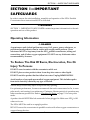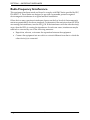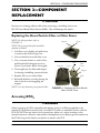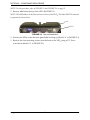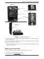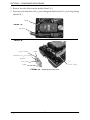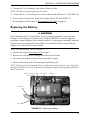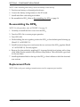
1
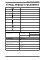
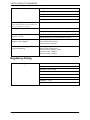
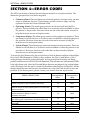
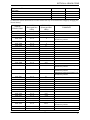
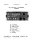
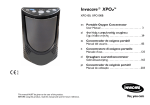
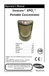
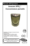
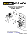
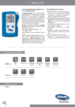
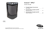
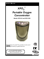
Service Manual
XPO2™
Portable Oxygen
Concentrator
Models XPO100 and XPO100B
0120
DEALER: Keep this manual. The procedures in this manual
MUST be performed by a qualified technician.
For more information regarding
Invacare products, parts, and services,
please visit www.invacare.com
WARNING
DO NOT USE THIS PRODUCT OR ANY AVAILABLE OPTIONAL
EQUIPMENT WITHOUT FIRST COMPLETELY READING AND
UNDERSTANDING THESE INSTRUCTIONS AND ANY ADDITIONAL
INSTRUCTIONAL MATERIAL SUCH AS OWNER’S MANUALS, SERVICE
MANUALS OR INSTRUCTION SHEETS SUPPLIED WITH THIS
PRODUCT OR OPTIONAL EQUIPMENT. IF YOU ARE UNABLE TO
UNDERSTAND THE WARNINGS, CAUTIONS OR INSTRUCTIONS,
CONTACT A HEALTHCARE PROFESSIONAL, DEALER OR TECHNICAL
PERSONNEL BEFORE ATTEMPTING TO USE THIS EQUIPMENT OTHERWISE, INJURY OR DAMAGE MAY OCCUR.
ACCESSORIES WARNING
INVACARE PRODUCTS ARE SPECIFICALLY DESIGNED AND
MANUFACTURED FOR USE IN CONJUNCTION WITH INVACARE
ACCESSORIES. ACCESSORIES DESIGNED BY OTHER
MANUFACTURERS HAVE NOT BEEN TESTED BY INVACARE AND ARE
NOT RECOMMENDED FOR USE WITH INVACARE PRODUCTS.
XPO2™
2
Part No 1150748
TABLE OF CONTENTS
TABLE OF CONTENTS
SPECIAL NOTES ................................................................................ 4
TYPICAL PRODUCT PARAMETERS .................................................... 5
Regulatory Listing .......................................................................................................................................6
SECTION 1—IMPORTANT SAFEGUARDS ............................................ 7
Operating Information...............................................................................................................................7
To Reduce The Risk Of Burns, Electrocution, Fire Or Injury To Persons...................................7
Radio Frequency Interference .................................................................................................................8
SECTION 2—COMPONENT REPLACEMENT ......................................... 9
Replacing the Gross Particle Filter or Filter Cover............................................................................9
Accessing XPO2 ..........................................................................................................................................9
Replacing the Inlet Filter .........................................................................................................................11
Replacing the Battery...............................................................................................................................12
Re-assembling the XPO2 ........................................................................................................................13
Replacement Parts....................................................................................................................................13
SECTION 3—CHECKING O2 PURITY ................................................. 14
SECTION 4—ERROR CODES ............................................................. 15
LIMITED WARRANTY ..................................................................... 19
Part No 1150748
3
XPO2™
SPECIAL NOTES
SPECIAL NOTES
Signal words are used in this manual and apply to hazards or unsafe practices which
could result in personal injury or property damage. Refer to the following table for
definitions of the signal words.
SIGNAL WORD
MEANING
DANGER
Danger indicates an imminently hazardous situation
which, if not avoided, will result in death or serious
injury.
WARNING
Warning indicates a potentially hazardous situation
which, if not avoided, could result in death or
serious injury.
CAUTION
Caution indicates a potentially hazardous situation
which, if not avoided, may result in property
damage or minor injury or both.
NOTICE
The information contained in this document is subject to change without notice.
DANGER
DO NOT SMOKE while using this device. Keep all matches, lit cigarettes, candles or
other sources of ignition out of the room in which this product is located and away
from where oxygen is being delivered.
NO SMOKING signs should be prominently displayed. Textiles and other materials
that normally would not burn are easily ignited and burn with great intensity in
oxygen enriched air. Failure to observe this warning can result in severe fire, property
damage and cause physical injury or death.
CAUTION
“Caution: Federal law restricts this device to sale or rental by or on order of a physician,
or any other practitioner licensed by the law of the State in which he/she practices to use
or order the use of this device.”
XPO2™
4
Part No 1150748
TYPICAL PRODUCT PARAMETERS
TYPICAL PRODUCT PARAMETERS
Direct Current
Type BF equipment
Attention - Consider Accompanying Documents
DO NOT smoke
Class II, Double Insulation
Power On/Off
DO NOT dispose of in household waste
Recycle
DO NOT use oil or grease
Keep dry
IPX1
Electrical Requirements:
Protected against dripping water
AC Power Supply:
120 VAC, 60 Hertz, 1.2 amps
230 VAC, 50 Hertz, 0.7 amps
DC Power Supply:
11 VDC, 6.5 amps
Rated Current Input:
3.8 amps at 18 VDC
Sound Level @ setting 2:
< 45dBA weighted
Altitude:
Up to 10,000 ft (3046 m) above sea level
Oxygen Concentration:*
*Based on an atmospheric pressure of 14.7 psi
(101 kPa) at 70°F (21°C)
87% to 95.6%, after initial warm-up period (approximately 5
minutes)
Oxygen Flow:
Pulse flow delivery. Bolus Volume Ranges From 300 - 840cc
settings 1 to 5.
Dimensions:
10” high x 7” wide x 4” deep (25.4 cm high x 17.8 cm wide x 10.2
cm deep)
Weight:
6.0 lbs (2.72 kg); 1.3 lbs (0.68 kg) for supplemental battery
Part No 1150748
5
XPO2™
TYPICAL PRODUCT PARAMETERS
Battery Duration (times are approximate):
Setting 1 = 3.5 hours
Setting 2 = 2.5 hours
Setting 3 = 2.0 hours
Setting 4 = 1.5 hours
Setting 5 = 1.0 hours
Battery Recharge Time:
NOTE: Recharge time increases if battery is
charging while unit is running.
4 hours
Humidity
Operating Humidity: 15% to 60% non condensing
Storage Humidity: up to 95% non condensing
Temperature Range:
(All power sources)
Operating temperature: 41°F to 95°F (5°C to 35°C)
Extended Temperature Range:
(Using AC or DC adapters)
Operating Temperature:
95°F to 104°F (35°C to 40°C)
Continuous use - all settings
Extended Temperature Range
(Using Internal Battery)
Operating Temperature:
95°F to 104°F (35°C to 40°C)
Continuous use - settings 1, 2 and 3
45 minutes (max) - setting 4
30 minutes (max) - setting 5
Storage temperature: -2°F to 140°F (-20°C to 60°C)
Regulatory Listing
ETL certified complying with:
EN 55011:1998
CISPR 11: 2003
IEC 60601-1; 2nd ed. 2005
IEC 60601-1-2; 2.1 ed.
IEC 61000-3-2:2005
IEC 61000-3-3:2005
UL 60601-1, 1st ed.
CSA 601.1 M90
XPO2™
6
Part No 1150748
SECTION 1—IMPORTANT SAFEGUARDS
SECTION 1—IMPORTANT
SAFEGUARDS
In order to ensure the safe installation, assembly and operation of the XPO2 Portable
Concentrator these instructions MUST be followed.
WARNING
SECTION 1 - IMPORTANT SAFEGUARDS contains important information for the safe
operation and use of this product.
Operating Information
DANGER
A spontaneous and violent ignition may occur if oil, grease, greasy substances, or
petroleum based products come in contact with oxygen under pressure. These
substances MUST be kept away from the XPO2 portable concentrator, tubing and
connections, and all other oxygen equipment. DO NOT use any lubricants unless
recommended by Invacare.
To Reduce The Risk Of Burns, Electrocution, Fire Or
Injury To Persons
DO NOT come in contact with the concentrator while wet.
DO NOT place or store product where it can drop into water or other liquid.
DO NOT reach for product that has fallen into water. Unplug IMMEDIATELY.
Avoid creation of any spark near medical oxygen equipment. This includes sparks
from static electricity created by any type of friction.
NEVER drop or insert any object or liquid into any opening.
For optimum performance, Invacare recommends that each concentrator be On, in autopulse mode, and running for a minimum of 5 minutes. Shorter periods of operation may
reduce maximum product life. Refer to Checking O2 Purity on page 15 for auto-pulse
mode.
A product should NEVER be left unattended when plugged in. Make sure XPO2 is Off
when not in use.
The XPO2 MUST be used in an upright position.
DO NOT connect the concentrator in parallel or series with other oxygen concentrators or
oxygen therapy devices.
Part No 1150748
7
XPO2™
SECTION 1—IMPORTANT SAFEGUARDS
Radio Frequency Interference
This equipment has been tested and found to comply with EMC limits specified by IEC/
EN 60601-1-2. These limits are designed to provide a reasonable protection against
electromagnetic interference in a typical medical installation.
Other devices may experience interference from even the low levels of electromagnetic
emissions permitted by the above standards. To determine if the emissions from the XPO2
are causing the interference, turn the XPO2 Off. If the interference with the other device(s)
stops, then the XPO2 is causing the interference. In such rare cases, interference may be
reduced or corrected by one of the following measures:
• Reposition, relocate, or increase the separation between the equipment.
• Connect the equipment into an outlet on a circuit different from that to which the
other device(s) is connected.
XPO2™
8
Part No 1150748
SECTION 2—COMPONENT REPLACEMENT
SECTION 2—COMPONENT
REPLACEMENT
CAUTION
Ensure not to damage ribbon cable when removing or installing front cover.
DO NOT use Methyl Ethyl Ketone (MEK). This will damage the plastic.
Replacing the Gross Particle Filter or Filter Cover
NOTE: For this procedure, refer to
FIGURE 2.1.
L
Cover
Magnet
NOTE: The gross particle filter should be
replaced as needed.
1. Lift filter cover slightly and pull down
to remove tabs from the grooves.
2. Lift out the filter from the filter cover.
3. Use a vacuum cleaner or wash with a
mild liquid dish detergent (such as
Dawn™) and water. Rinse thoroughly.
Tabs
Grooves
4. Thoroughly dry the filter and inspect
for fraying, crumbling, tears and holes.
Cover
Filter
Cover
Magnet
Filter
5. Replace filter cover and/or filter.
6. Reinstall the filter cover by placing the
tabs in the slots and engaging the
magnet.
NOTE: Use only Invacare gross particle filter.
FIGURE 2.1 Replacing the Gross Particle
Filter or Filter Cover
Accessing XPO2
WARNING
When accessing the XPO2 remember that battery power is still being applied to the
internal (PCB) printed circuit board. Care MUST be taken to minimize contact with the
PCB. DO NOT use any kind of tool (screwdriver, pliers, etc.) when working on the
internal structure, otherwise, injury and/or damage may occur. Battery power remains on
the PCB as long as the battery connection is made to the PCB.
Part No 1150748
9
XPO2™
SECTION 2—COMPONENT REPLACEMENT
NOTE: For this procedure, refer to FIGURE 2.2 and FIGURE 2.3 on page 11.
1. Remove label from the top of the XPO2 (FIGURE 2.2).
NOTE: This label adheres to the front and rear sections of the XPO2. This label MUST be removed
to separate the two sections.
Label
XPO2
FIGURE 2.2 Remove/Install label
2. Position the XPO2 so that the back panel label is facing up (Detail “A” in FIGURE 2.3).
3. Remove the four mounting screws from the back of the XPO2 using a T15 Torx®
screwdriver (Detail “A” in FIGURE 2.3).
XPO2™
10
Part No 1150748
SECTION 2—COMPONENT REPLACEMENT
DETAIL “B”
DETAIL “A”
Mounting Screws
Front Cover
Ribbon Cable
Inlet Filter
Back Panel Label
Tubing
Mounting Screws
Front Cover
DETAIL “C”
Ribbon Cable
PC Board
FIGURE 2.3 Removing the Front Cover
4. While holding the unit together rotate the XPO2 and position it so that the back panel
label is facing down.
NOTE: The ribbon cable is connected to the front cover and the pc board. Only open the
XPO2 as shown in Details “B” and “C”.
5. Slowly, open the front cover ensuring not to damage the ribbon cable (Detail “B” and
Detail “C” in FIGURE 2.3).
Replacing the Inlet Filter
NOTE: For this procedure, refer to FIGURE 2.4 and FIGURE 2.2 on page 10.
NOTE: The inlet filter should be replaced as needed.
1. Perform the steps in Accessing XPO2 on page 9.
Part No 1150748
11
XPO2™
SECTION 2—COMPONENT REPLACEMENT
2. Remove the inlet filter from the holder (Detail “A”).
3. Disconnect the inlet filter with 5/8-inch tubing attached from the 111/2-inch long tubing
(Detail “B”).
Holder
DETAIL “A”
Inlet Filter
DETAIL “B”
5/ -Inch
8
Intake
Tubing
Inlet Filter w/ 5/8-inch Tubing
Attached
Flow Arrow
111/2-inch Tubing
Outlet
FIGURE 2.4 Replacing the Inlet Filter
XPO2™
12
Part No 1150748
SECTION 2—COMPONENT REPLACEMENT
4. Transfer the 5/8-inch tubing to the intake of the new filter.
NOTE: The flow arrow points away from the intake.
5. Connect the 11½- inch tubing to the outlet of the inlet filter (Detail “A” of FIGURE 2.4).
6. Position and orient the new filter in the holder (Detail “B” of FIGURE 2.3).
7. Re-assemble the XPO2. Refer to Re-assembling the XPO2 on page 14.
Replacing the Battery
CAUTION
Before handling the P.C. board, ensure you are properly grounded to prevent static
damage to the components of the board. A static cuff MUST be worn and properly
grounded using an alligator clip. Electrical conduit or a water pipe is normally sufficient
when a known good ground in unavailable. Care should be taken to ensure that the
alligator clip contacts a bare metal surface.
NOTE: For this procedure, refer to FIGURE 2.5.
1. Perform the steps in Accessing XPO2 on page 9.
2. Remove the inlet filter with tubing attached from the holder.
3. Disconnect the battery wiring harness from the PC board.
4. Remove the battery from the thermal pad and battery tray.
NOTE: The thermal pad is between the battery and the bottom of the tray. It is a soft “dough-like”
material that adheres to the tray. If thermal pad is damaged or pulled up during battery removal it
MUST be replaced.
Battery Wiring Harness
connects here
PC Board
Battery
Inlet Filter
Tubing
FIGURE 2.5 Replacing the Battery
Part No 1150748
13
XPO2™
SECTION 2—COMPONENT REPLACEMENT
NOTE: When installing new battery, ensure the battery is label side up.
5. Position new battery on thermal pad as shown.
6. Connect the battery wiring harness to the PC board.
7. Install inlet filter with tubing into holder.
8. Re-assemble the XPO2. Refer to Re-assembling the XPO2 on page 14.
Re-assembling the XPO2
NOTE: For this procedure, refer to FIGURE 2.3 on page 11.
1. Carefully, re-install the front cover onto the XPO2.
2. Turn the XPO2 On to ensure proper operation.
3. Turn XPO2 Off.
4. While holding the unit together, position the XPO2 so that the back panel is facing up
(Detail “A” in FIGURE 2.3).
5. Install four mounting screws and secure the two sections of the XPO2 together (Detail
“A” in FIGURE 2.3). Securely tighten.
6. Remove the glue residue by applying 91% isopropyl alcohol, and wiping with a clean
cloth. Make sure the surface is dry and free of any residue. This will ensure a good seal
for the new label.
7. Install replacement label on the top of the XPO2 so that it adheres to both the front and
rear sections.
Replacement Parts
NOTE: Refer to the parts catalog at www.invacare.com for component part number.
XPO2™
14
Part No 1150748
SECTION 3—CHECKING O2 PURITY
SECTION 3—CHECKING O2 PURITY
NOTE: Although the XPO2 offers pulse dose only, the oxygen purity can be checked with a hand
held oxygen analyzer.
NOTE: Oxygen purity should be checked annually or every 4,320 hours, whichever comes first.
1. Turn the unit On.
2. Press the “+” button to increase the flow to setting 5.
3. Simultaneously press and hold the “+” and “battery gauge” buttons until the #5 BLUE
indicator light blinks. This is your indication that the unit is now in auto-pulse mode.
NOTE: The unit will remain in auto-pulse mode until it is set to a lower flow setting or is turned
off.
4. Connect a standard hand held oxygen analyzer to the outlet port.
5. Follow the directions provided by the analyzer manufacturer. Some analyzers will
also measure flow and pressure, but only if connected to a continuous flow of oxygen
(so these options are not usable on this pulse only unit).
NOTE: The purity reading may fluctuate slightly due to the pulse flow. It is recommended that you
record a high and a low over a 60 second time period. The XPO2 is functioning properly when the
purity levels are above 87%, after the 5 minute warm-up period.
Part No 1150748
15
XPO2™
SECTION 4—ERROR CODES
SECTION 4—ERROR CODES
The XPO2 has dozens of alarms that are being monitored on a continuous basis. The
alarms are grouped into four main categories:
• Common Alarms: These are alarms for which the patient, or the provider, can take
action to eliminate the issue. These alarms, and the corrective steps, are fully
explained within the Owner’s Manual (OM).
• Operating Alarms: This alarm group centers on the sieve beds and the PSA
process. These are alarms for which there is no corrective action available to either
the patient or the provider. However, there are sub-codes that can be accessed to
help the Invacare service and repair centers.
• Compressor Alarms: This alarm group centers on the compressor operation. These
are alarms for which there is no corrective action available to either the patient or
the provider. However, there are sub-codes that can be accessed to help the
Invacare service and repair centers.
• System Alarms: This alarm group centers on internal software monitors. These are
alarms for which there is no corrective action available to either the patient or the
provider (*). However, there are sub-codes that can be accessed to help the
Invacare service and repair centers.
To access the Sub-Alarm codes, the unit first has to be in an alarm condition with multiple
flow level LEDs illuminated. While in this condition, the Plus (+) and Minus (-) flow
setting buttons should be pushed and held. As long as both these buttons are being
pushed, a different set of flow LEDs will illuminate. This alternate set of illuminated LEDs
is the sub-alarm code. Once the Plus and Minus buttons are released, the original alarm
code will return. Once the unit is turned off, the alarm codes displays will be reset. All the
alarms should be reset and the unit turned back on to see if the unit can self-correct the
problem. If the alarms persist, please contact your nearest Invacare repair center.
ERROR / ERROR CODE
ALARM
(Illuminated flow
LEDs)
SUB-ALARM
(Illuminated flow
LEDs)
1, 2
None
1, 3
None
1, 4
None
1, 5
None
3, 4
3, 4
3, 4
None
1
2
Common Alarms
Internal temperature of the unit is either too hot, or too cold,
to allow compressor to start. See OM for instructions.
While operating, the internal temperature of the unit becomes
either too hot, or too cold, to allow operation to continue. See
OM for instructions.
The internal battery temperature is either too hot, or too cold,
to allow operation on battery to continue.
See OM for instructions.
Control panel button was found to be continuously pressed
upon power-up (a.k.a. stuck button). See OM for instructions.
Operating Alarms
Code: 3000
Code: 3001
Code: 3002
XPO2™
16
Part No 1150748
SECTION 4—ERROR CODES
Compressor Alarms
Code: 6000
Code: 6001
Code: 6002
Code: 6003
4, 5
4, 5
4, 5
4, 5
None
1
2
1,2
(*) Within the System Alarms there are a few alarms that may correct themselves simply by changing the
internal battery.
ALARM
(Illuminated flow
LEDs)
SUB-ALARM
(Illuminated flow
LEDs)
Code: 7000
Code: 7001
3, 4, 5
3, 4, 5
None
1
Code: 7002
3, 4, 5
2
Code: 7003
Code: 7004
Code: 7005
Code: 7006
Code: 7007
Code: 7008
Code: 7009
Code: 700a
Code: 700b
Code: 700c
Code: 700d
3, 4, 5
3, 4, 5
3, 4, 5
3, 4, 5
3, 4, 5
3, 4, 5
3, 4, 5
3, 4, 5
3, 4, 5
3, 4, 5
3, 4, 5
1,2
3
3,1
3,2
3,2,1
4
4,1
4,2
4,2,1
4,3
4,3,1
Code: 700e
3, 4, 5
4,3,2
Code: 700f
3, 4, 5
4,3,2,1
Code: 7010
3, 4, 5
5
Code: 7011
Code: 7012
Code: 7013
Code: 7014
Code: 7015
Code: 7016
Code: 7017
Code: 7018
Code: 7019
Code: 701a
Code: 701b
Code: 701c
3, 4, 5
3, 4, 5
3, 4, 5
3, 4, 5
3, 4, 5
3, 4, 5
3, 4, 5
3, 4, 5
3, 4, 5
3, 4, 5
3, 4, 5
3, 4, 5
5,1
5,2
5,2,1
5,3
5,3,1
5,3,2
5,3,2,1
5,4
5,4,1
5,4,2
5,4,2,1
5,4,3
Code: 701d
3, 4, 5
5,4,3,1
Code: 701e
Code: 701f
3, 4, 5
3, 4, 5
5,4,3,2
5,4,3,2,1
ERROR/
ERROR CODE
COMMENTS
System Alarms
Part No 1150748
17
Replacement of the internal battery may
eliminate this problem
Replacement of the internal battery may
eliminate this problem
Replacement of the internal battery may
eliminate this problem
Replacement of the internal battery may
eliminate this problem
Replacement of the internal battery may
eliminate this problem
XPO2™
NOTES
NOTES
XPO2™
18
Part No 1150748
LIMITED WARRANTY
LIMITED WARRANTY
For warranty information, please refer to the original owner's manual which came with this product,
or contact Invacare for more information.
Part No 1150748
19
XPO2™
www.invacare.com
USA
One Invacare Way
Elyria, Ohio USA
44036-2125
800-333-6900
Technical Services
440-329-6593
800-832-4707
Canada
570 Matheson Blvd E Unit 8
Mississauga Ontario
L4Z 4G4 Canada
800-668-5324
EC
REP
EU Representative
Invacare Deutschland
GmbH
Kleiststraße 49
D-32457 Porta
Westfalica
Tel: (49) (0) 5731 754 0
Fax: (49) (0) 5731 754
52191
© 2013 Invacare Corporation.
All rights reserved. Republication,
duplication or modification in whole or in
part is prohibited without prior written
permission from Invacare. Trademarks are
identified by ™ and ®. All trademarks are
owned by or licensed to Invacare
Corporation or its subsidiaries unless
otherwise noted.
Torx is a registered trademark of Textron,
Inc.
Dawn is a trademark of The Proctor and
Gamble Company.
0120
Invacare Corporation
Part No 1150748
Rev D - 10/17/13