1
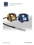
Wyco Operator’s and Service Manual
Electric Flex Shaft Concrete Vibrators
®
General Safety Rules
Failure to follow all instructions listed below may result
in electric shock, fire and/or serious personal injury.
C
®
US
LISTED
3LFS
WARNING
Work Area
Personal Safety (continued)
1. Keep your work area clean and well lit. Cluttered benches and
dark areas invite accidents.
2. Do not operate power tools in explosive atmospheres, such as
in the presence of flammable liquids, gases, or dust. Power
tools create sparks which may ignite the dust or fumes.
3. Keep bystanders, children, and visitors away while operating
a power tool. Distractions can cause you to lose control.
3. Avoid accidental starting. Be sure switch is off before
plugging in. Carrying tools with your finger on the switch or
plugging in tools that have the switch on invites accidents.
4. Remove adjusting keys or switches before turning the tool on.
A wrench or a key that is left attached to a rotating part of the tool
may result in personal injury.
5. Do not overreach. Keep proper footing and balance at all
times. Proper footing and balance enables better control of the tool
in unexpected situations.
6. Use safety equipment. Always wear eye protection. Dust mask,
non-skid safety shoes, hard hat, or hearing protection must be used
for appropriate conditions.
Electrical Safety
1. Grounded tools must be plugged into an outlet properly
installed and grounded in accordance with all codes and
ordinances. Never remove the grounding prong or modify the
plug in any way. Do not use any adaptor plugs. Check with a
qualified electrician if you are in doubt as to whether the
outlet is properly grounded. If the tools should electrically
malfunction or break down, grounding provides a low resistance path
to carry electricity away from the user.
2. Double Insulated tools are equipped with a polarized plug (one
blade is wider than the other). This plug will fit in a polarized
outlet only one way. If the plug does not fit fully in the outlet,
reverse the plug. If it still does not fit, contact a qualified
electrician to install a polarized outlet. Do not change the plug
in any way. Double Insulation elimates the need for the three wire
grounded power cord and grounded power supply system.
3. Avoid body contact with grounded surfaces such as pipes,
radiators, ranges and refrigerators. There is an increased risk of
electric shock if your body is grounded.
4. Do not abuse the cord. Never use the cord to carry the tools
or pull the plug from an outlet. Keep cord away from heat, oil,
sharp edges or moving parts. Replace damaged cords
immediately. Damaged cords increase the risk of electric shock.
5. When operating a power tool outside, use an outdoor
extension cord marked “W-A” or “W”. These cords are rated for
outdoor use and reduce the risk of electric shock.
Personal Safety
1. Stay alert, watch what you are doing and use common sense
when operating a power tool. Do not use tool while tired or
under the influence of drugs, alcohol, or medication. A moment
of inattention while operating power tools may result in serious
personal injury.
2. Dress properly. Do not wear loose clothing or jewelry. Contain
long hair. Keep your hair, clothing, and gloves away from
moving parts. Loose clothes, jewelry, or long hair can be caught in
moving parts.
Tool Use and Care
1. Use clamps or other practical way to secure and support the
workpiece to a stable platform. Holding the work by hand or
against your body is unstable and may lead to loss of control.
2. Do not force tool. Use the correct tool for your application.
The correct tool will do the job better and safer at the rate for which it
is designed.
3. Do not use tool if switch does not turn it on or off. Any tool that
cannot be controlled with the switch is dangerous and must be repaired.
4. Disconnect the plug from the power source before making any
adjustments, changing accessories, or storing the tool. Such
preventive safety measures reduce the risk of starting the tool accidentally.
5. Store idle tools out of reach of children and other untrained
persons. Tools are dangerous in the hands of untrained users.
6. Maintain tools with care. Keep cutting tools sharp and clean.
Properly maintained tools, with sharp cutting edges are less likely to
bind and are easier to control.
7. Check for misalignment or binding of moving parts, breakage
of parts, and any other condition that may affect the tools
operation. If damaged, have tool serviced before using. Many
accidents are caused by poorly maintained tools.
8. Use only accessories that are recommended by the
manufacturer for your model. Accessories that may be suitable
for one tool, may become hazardous when used on another tool.
Service
1. Tool service must be performed only by qualified repair
personnel. Service or maintenance performed by unqualified
personnel could result in a risk of injury.
2. When servicing a tool, use only identical replacement parts.
Follow instructions in the Maintenance section of this manual.
Use of unauthorized parts or failure to follow Maintenance Instructions
may create a risk of electric shock or injury.
Specific Safety Rules and/or Symbols
V
A
Hz
volts
Functional Description
amperes
The vibrator motor is used to power concrete flex shaft vibrators
which provide vibration to consolidate freshly poured concrete.
The vibration is created by an eccentric weight inside the vibrator
head that generates a pulse once per revolution. Use only the
motor head and shaft combinations listed in the chart below.
hertz
alternating current
Class II Construction
splash-proof construction
Ground Terminal (protective earthing)
12
902A, 992A
6 902A-230, 992A-230
ON
OFF
15
7.5
Identification Symbol
For identification, in case the name plate has been removed, a
code has been stamped on the die cast housing as shown in
Figure 1 below. Order only identical replacement parts. Be sure
to include part number, description, and quantity when ordering.
FIGURE 1
I.D. Symbol
Model
115V Stamp
230V stamp
902/992A
903/993
2A
3
2V
3V
2
903, 993
903-230, 993-230
13/16
1
1-3/8
1-3/4
1-3/8
1-3/4
2
2-1/4
750-D
750-EH
750-FI
750-GI
750-FI
750-GI
750-LI
750-MI
2-20 FT
8900
9500
2-20 FT
9500
Assembly Drawings
Marking
on End Cap
D
EH
1.38B
1
Square
Size
13/16"
1"
1-3/8"
2
Marking
on End Cap
1.75B
2.00B
2.25B
Assembly
Part #
877520
877526
878533
3
Square
Size
1-3/4"
2"
2-1/4"
Assembly
Part #
878540
878563
878568
2
4
LOCTITE 545
No
Description
1
Nut, Hex Jam
2
Bearing, Ball
3 Housing, Square
4
Rotor
5
O-Ring, Buna
1
2
Qty
1
4
1
1
1
D
435638
097011
587320
717340
*
No
6
7
8
9
Description
Holder, Seal
Seal, Oil
Bushing
Driver, Hex
Qty
1
2
1
1
PERMATEX #2
* All of these items are available assembled in Kit #747540
2
5
6
8
7
LOCTITE 545
Qty
1
4
1
1
2
10 3
EH
432710
097012
587325
717345
No
6
7
8
Description
Bushing
End Cap
Driver, Hex
Qty
1
1
1
**
384447
** End Cap Assy with seals is Part #207248. (Order bushing separately)
**
4
10
5
1.38B 1.75B
2.00B
2.25B
432708
432707
887015
887011
096013 096010 096011 096020
588331 588339 588354 588368
718357 718335 717360 718365
No
6
7
8
9
10
Description
Washer, Flat
Seal, Oil
End Cap
Driver, Hex
Shim
3
6
8
7
9
PERMATEX #2
LOCTITE 545
LOCTITE 545
Qty
1
1
4
1
1
PERMATEX #2
EH
177325
LOCTITE 545
No
Description
1
Nut, Hex Jam
2
Washer, Flat
3
Bearing, Ball
4 Housing, Square
5
Rotor
9
*
*
*
382428
4
2
8
D
LOCTITE 545
1
7
6
LOCTITE 545
3
No
Description
1
Nut, Hex Jam
2
Bearing, Ball
3 Housing, Square
4
Rotor
5
Seal, Oil
5
Qty
1
2
1
1
2
1.38B 1.75B
887015
2.00B
2.25B
887016
***
***
384446
419701
N/A
Manufacturer suggests using End Cap with pressed in seals (1.38B - #208231) (1.75B - #208236) (2.00B - #208261) (2.25B - #208268)
However Seal and End Cap are available separately upon request.
***
3
Electric Concrete Vibrator Assembly Drawings
14
15
17
18
19
34
22
20
21
37
23
38 *
24
12
26
15
32
36
13
1
35
28
2
* Electrical Tape
33
31
27
Taping Instructions
1. Two .75 inch strips covering spring holes on each side of toggle.
2. Two 1.75 inch strips covering face plate holes and rivets
extending over sides of switch.
3. Two 4 inch strips covering switch wires
(Bottom first from edge of cord clamp. Top next with tape starting
about half way through switch depth)
4. One 12 inch strips make two wraps around switch.
29
30
Model
Number
115V Wire
Color
230V Wire
Color
902A /992A
903 /993
Yellow
Black
Yellow
Black
6
Model
Number
115V Wire
Color
230V Wire
Color
902A /992A
903 /993
White
White
Red
Red
10
16
11
9
A
5
A
4
3
8
25
SECTION A-A
7
4
Electric Concrete Vibrator Drawing Parts List
Parts List (see drawings on page 4)
Item
1
2
3
4
5
6
7
8
9
10
11
12
13
14
15
16
17
18
19
20
21
22
23
23
24
25
26
27
28
29
30
31
32
33
34
35
36
37
38
Description
115V
115V
115V
115V
230V
12 AMP 12 AMP 15 AMP 15 AMP 6 AMP
Qty 902A
992A
903
993
902A
1
End Cap, Plastic; Elect Motor; Gold
Screw, Hex Head; Plastic; 1/4-20 x 1/2 4
1
Clamp, Cord
1
Bracket, Cord Clamp
2
Nut, Lock; 8-32; Nylon Insert; Zinc
4
Stud, Motor Housing
1
Cord Set, w/Plug
1
Bend Relief
4
Screw, Pan Head; #8-32 x 3/8 Long
4
Washer, Lock; #8
2
Clamp, Brush Holder
1
Filter
1
Switch, Toggle
1
Spring, Loading
2
Bearing, Ball; 1.18OD; .394 Bore
2
Retainer, Brush
2
Holder, Brush
2
Assy, Brush & Spring
2
Nut, Hex; #10-32
1
Field
1
Assy, Armature
2
Washer, Lock; #10
2
Screw, Field; #10-32 x 3-5/8
2
Screw, Field; #10-32 x 3
1
Sleeve, Field
1
Grounding Insert
4
Screw, Hex Thd Cut; 1/4-20 x 5/8
2
Frame, Tube; Inner
2
Frame, Tube; Outer
1
Support, Rubber Frame
4
Rivet, Pop; Steel Plated
4
Bushing
1
Driver, Hex; Motor; Black Oxide
1
Housing, Motor; Painted
1
Housing, Inner Motor
1
Connector, Motor; Zinc Plated
1
Hex Panel Nut
1
Switch Tent
25"
Electrical Tape, .75 wide
415304 415399
415330 415338
415304
415330
415335
415308
415324
415326
415512
415309
415399 415306
415335 415330
415359
415360
415322
415554
415361
415333
099909
415323
415515
230V
230V
230V
6 AMP 7.5 AMP 7.5 AMP
992A
903
993
415401 415306
415338 415330
415525
415401
415338
415230
415363
415211
415209
415511
415509
—
415212
765210
—
175512
—
—
—
415400
415367
415368
415221
415219
415362
—
415358
—
415212
765510
765210
—
175512
—
175512
435510
415528
415529
415315
415311
415310
415518
415526
415519
465513
—
415400
—
415400
—
415367
—
415367
—
415368
—
415368
415521
415539
415358
—
765510
—
175512
—
—
—
415400
415367
415368
Operation
• Inspect the vibrator for damage prior to using this equipment.
Read, understand and follow all safety and maintenance
instructions in this manual. Carefully check that the power cord
has no cuts or exposed wires and that the vibrator housing is
intact. Do not use damaged equipment.
• Insure that the motor, shaft and head are connected securely
as described in the maintenance instructions.
• Insure that the plug is connected to the appropriate power source.
• Insure that the motor is not immersed in concrete and that any
cord connections are not in water or fresh concrete.
• Turn vibrator on using switch by moving the toggle to the 1 or
on position.
• Insert the vibrator head vertically into the concrete to be
consolidated.
• Do not run the vibrator head outside of fresh concrete for an
extended period of time, since the vibrator depends on moving
concrete to cool the bearings.
• Avoid sharp bends in the flex shaft during operation. Sharp
bends reduce shaft life.
• Remove head from concrete and turn switch to the off position.
5
Service and Maintenance Instructions
Service the vibrator head after every 50 hours of operation to insure trouble-free running on the job.
When servicing, always replace hex driver, seals and bearings.
(Or bushing for D & EH Heads) - (See drawings Page 3)
All heads are equipped with seals at the flexible shaft end. All heads
contain oil, the seals serve a double purpose, to keep the oil in the
head and to keep the grease from the flexible shaft out of the head.
Loosen
1. Hold the nose end in a vise and unscrew the end cap
(counter-clockwise) with a chain wrench or a good pipe wrench.
Note: Hexagon Driver has left hand threads
3. Flush rotor assembly and housing with solvent and wipe all
parts clean. Replace bearings, seals and hex driver. Maintain
concentric alignment of hex driver with respect to rotor shaft.
Refill with proper amount of Wyco No. 514-O non-foaming
vibrator oil. Apply Loctite 545 or equivalent to threads on both
ends of rotor.
See Chart Below
Loosen
HEAD OIL REQUIREMENTS
Head Size
D - 13/16" Square
EH - 1" Square
1.38B - 1-3/8" Square
1.75B - 1/3/4" Square
2.00B - 2" Square
2.25B - 2-1/4" Square
2. Pull the eccentric rotor assembly out of the housing. (If the
bearings are stuck and you have difficulty removing them from
the housing, screw end cap partly back into the housing and
bounce the head and cap down on a block of wood, in order
to loosen the bearings from their seat, then pull out the
rotor assembly.)
Oil Required
1/2 ounce
3/4 ounce
1 ounce
1-1/4 ounces
2 ounces
3-1/2 ounces
4. Replace rotor assembly in head housing. Apply Loctite 545
adhesive/sealant or equivalent all around the threads of the end
cap. Tighten and wipe off excess Loctite 545 adhesive/sealant.
Flexible Shaft - Lubrication
involves repeatedly coiling the flex shaft from the head to the motor
while the motor is running. The flex shaft should be coiled and
uncoiled repeatedly until the amperage to operate the vibrator is
reduced and remains constant. It must be reduced to a level lower
than the rated amperage on the name plate. If an ammeter is not
available, an increase in speed (RPM) can be heard. The coiling and
uncoiling should be repeated until the speed increases and remains
constant. If this procedure is not followed, additional torque will be
required from the motor, thus reducing the motor life.
When vibrators are shipped completely assembled from the factory,
the shafts are lubricated and broken-in. If separate cores and casings
are shipped, they require the following lubrication and break-in
procedure.
To lubricate, lightly coat the core with grease (514-B Wyco shaft
lubricant) while inserting it into the casing. Do not over lubricate since
the surplus lubricant may get past the seal in the vibrator head. Over
lubrication will also increase the amount of torque required to operate
the vibrator resulting in additional stress on the motor and possibly
early core and casing failure.
NOTE: When attaching Vibrator Head to Flexible Shaft casing,
always use Permatex Form-a-Gasket No. 2 on the threads.
When adding lubricant on the job, after each 50 hours of operation,
loosen the casing from the motor and pull out the core about 15 to 18
inches. Apply lubricant as above to the exposed section of core.
Reinstall core insuring that it engages with the vibrator head. During
operation the grease will travel the full length of the casing.
One of the greatest enemies of satisfactory performance of Vibrator
Heads is water. As the head is submerged in the mix, water and
cement try to get into the head. In addition to tightening the head
onto the flexible shaft tightly, the threads must be coated with
“Permatex Form-a-Gasket #2.” This must be done each and every
time that the head is removed and re-installed.
A break-in procedure is required after the assembly of seperately
shipped core & casing. This procedure
6
Wyco Motor Service and Maintenance Instructions
Wyco vibrator motors are designed to operate 50 to 100 hours between normal “preventive maintenance” intervals. The
service instructions below should be followed if it becomes necessary to replace brushes, switch or cord.
NOTE: Use only factory authorized replacement parts.
BRUSH REPLACEMENT — REMOVAL:
REPLACEMENT:
A. Disconnect line cord (7) from power source.
B. Secure motor in upright position [switch (13) up] by
clamping external portion of motor connector (35) in a
bench vise.
C. Remove four plastic bolts (2) and lift off end cap (1).
D. Loosen the pan head screw (9) that holds brush retainer (16)
by a 1/4 turn.
E. The brush spring will pop out. Carefully remove the brush (18)
by gently pulling on the spring.
F. Repeat steps for the opposite side.
E. Position new switch (13) on mounting lugs on inner motor
housing (34).
Note: Vertical slot in threaded barrel of switch (13) must
be toward line cord (7) in order to have ON-OFF switch
positions agree with marking on end cap (1).
F. Position each of the four wires to the same terminal location
previously used.
G. Assemble four screws through lead terminals and tighten
securely to switch (13).
H. On grounded motors only, tape switch with item (38), slide
switch tent (37) on switch and secure with hex nut (36).
I. Replace end cap (1), filter (12) and four plastic bolts (2).
Note: If brushes are worn to 3/8" (9 mm) or less, they
should be replaced.
REPLACEMENT:
POWER CORD REPLACEMENT — REMOVAL:
G. Align new brush (18) with brush holder (17) and insert.
Note: Avoid chipping brush edges when inserting.
Note: Ensure that milled slot on brush holder (17) mates
with brush clamp (11) and longer end of brush holder
(17) is toward armature (21).
A. Disconnect line cord (7) from power source.
B. Secure motor in upright position [switch (13) up] by clamping
hex portion of motor connector (35) in a vise.
C. Remove four plastic bolts (2) and lift off end cap (1).
D. Remove the two screws holding cord set (7) leads to switch (13).
E. Alternately loosen lock nuts (5) until they are flush with top of
cord bracket (4).
Note: Do not remove nuts (5) from cord bracket (4).
F. Remove cord (7) from under cord clamp (3).
G. Note approximate position of bend relief (8) on old cord
(7) and remove it for reuse.
H. Feed spring into brush holder (17), hold spring in place
and reposition brush retainer (16). Tighten pan head screw (9)
while holding brush retainer (16) firmly against brush holder (17).
J. Repeat steps for the opposite side.
K. Replace end cap (1) and four plastic bolts (2).(See illustration
on bottom of Page 4)
Note: Do not over tighten bolts!
REPLACEMENT:
SWITCH REPLACEMENT — REMOVAL:
H. Position bend relief (8) on new cord (7) in approximate
position to fit into grooves in inner motor housing (34).
J. Insert new cord (7) through open cord clamp (3).
K. Position cord (7) so the screw terminals on cord leads are
aligned with screws and lead colors match the drawing.
L. Assemble two screws through lead terminals and tighten
securely to switch (13) as shown.
M. Hold switch (13) firmly in position on inner motor housing
(34) lugs. Firmly position cord (7) and bend relief (8) into
their molded nests in the inner motor housing (34). Reposition
bend relief (8), if necessary, to eliminate stretching or kinking
of cord (7) between switch terminals and bend relief (8).
N. Hold cord (7) and bend relief (8) firmly in place and alternately
tighten the two lock nuts (5) until switch (13), cord (7), and
cord clamp (3) are tightly secured.
A. Disconnect line cord (7) from power source.
B. Secure motor in upright position [Switch (13) up] by
clamping hex portion of motor connector (35) in a vise.
C. Remove four plastic bolts (2) and lift off end cap (1).
D. On grounded motors remove hex nut (36), switch tent (37)
and tape (38). Remove four screws that secure wire leads to
switch (13) and remove it from inner motor housing (34).
Note: The switch terminals that each wire is connected
to and the vertical slot in threaded barrel of switch (13)
faces toward line cord (7).
Note: Be sure cord clamp (3) is clamping outer jacket of
cord (7) and not on the wire leads.
P. Replace end cap (1) and four plastic bolts (2).
7
When selecting an extension cord for use with Wyco electric
motor cord sets using a 2-prong polarized plug(double insulated
motors), an equivalent plug set must be used. Extension cords
must be approved for outdoor use and the wire gauge of the
cord must be selected from the following table.
Extension Cord Wire Minimum Size Requirements
Motor
Number Volts
902A
992A
903
993
902A
992A
903
993
115
115
115
115
230
230
230
230
Rated
Amps
AWG
12
12
15
15
6
6
7.5
7.5
16
16
14
14
18
18
18
18
WYCO TOOL
8635 Washington Avenue
Racine, WI 53406-3738 USA
®
Tel: (262) 639-6770 or 800-233-9926
Fax: (262) 639-2023 or 888-992-6872
Website: www.wycotool.com
E-Mail: [email protected]
© 2008 Racine Federated Inc., all rights reserved
FORM NO. W150
KB PRINTED IN USA 6/08