1
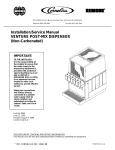
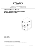
PLUNGER PUMP SERVICE MANUAL
5 Series
INSTALLATION AND START-UP INFORMATION
Optimum performance of the pump is dependant upon the entire liquid system and will be obtained
only with the proper selection, installation of plumbing for the pump and accessories.
SPECIFICATIONS: Maximum specifications refer to individual attributes and
may have qualifications. It is not implied that any maximums can be
performed concurrently. If more then one maximum is considered, check
with your Arimitsu Pumps supplier of Arimitsu of N.A. to confirm the proper
performance, environment, system design and pump selection. Refer to the
respective Product Data Sheet (PDS) for complete specification, parts lists,
performance charts and exploded view.
LUBRICATION: Fill crankcase with Arimitsu pump oil (p/n 30103) to required
level. DO NOT RUN PUMP WITHOUT OIL IN CRANKCASE. Change oil
according to the following schedule; after the first 30 hours, then every
500 hours or once per year which ever comes first. Additional lubrication
may be required with increased hours of operation, temperature, and
various environments.
PUMP ROTATION: Pump was designed for forward rotation, unless
otherwise noted by a directional arrow. If rotating counter to arrow,
additional oil should be added to aid lubrication. Fill to slightly above the
upper line on dipstick to assure adequate lubrication.
PULLEY SELECTION: Select size of motor pulley required to deliver the
desired flow. Be careful to choose a pulley with the proper horsepower
capacity. Horsepower requirement can be found on PDS for each respective
model. Use formula found on formulas page as a guide to pulley selection.
Note: Use the same pitch size pulleys for both pump and motor.
DRIVE SELECTION: The motor or engine driving the pump must be of
sufficient horsepower to maintain full RPM when the pump is at the desired
load. Select the electric motor from the Horsepower chart according to
required pump discharge flow, maximum pressure at the pump and drive
losses of approximately 5%. Consult the manufacturer of gas or diesel
engine for selection of the proper engine size. Use formula found on
formulas page as a guide for HP calculation.
The quotient will indicate the minimum HP size of motor to select. Please
choose a HP size larger when possible to allow for system inefficiencies such
as line loss and plumbing irregularities.
MOUNTING:
Choose a level horizontal surface that will allow access for maintenance and
visual inspection. The surface must be able to withstand vibration and be
strong enough to support the pump.
Use flexible hose for inlet and discharge connections on the pump to
minimize possible system stresses. Never connect rigid pipe to the inlet of
discharge of the pump.
Make sure the pump crankshaft and motor crankshaft are parallel and
mounted pulleys are in the straight line. Misalignment will lead to a loss of
performance and premature belt failure, in addition to damaging the pump
and/or motor.
• Choose a properly-rated belt for the HP of the system. Tighten to the
specifications recommended by the belt manufacturer. Do not over
tighten. Hand rotate pump pulley prior to starting to verify shaft and
bearings are free moving.
• Protect pump from humidity, dirt, heat, water spray and chemical
exposure.
Arimitsu of North America, Inc.
700 McKinley St. NW
Anoka, MN 55303
ph: 763.433.0303 • fax: 763.433.0404
arimitsupumps.com
PLUMBING:
INLET: When done correctly, inlet plumbing will positively benefit the
system. If you have any questions, please contact Arimitsu Pumps.
• DO NOT STARVE PUMP OR RUN DRY
• As a minimum requirement, use a hose one size larger than the inlet
port size.
• The pump will work best with a pressurized inlet that does not exceed
the maximum recommended on the specification sheet.
• Every pump is designed for suction lift (vacuum) inlet conditions,
however optimum performance is obtained with a pressurized inlet.
In cases such as hot or thick liquids, or high speed a positive inlet is
recommended.
• Several long-term failures result from improperly plumbed inlet
systems such as, valve breakage, manifold washout, seal failure,
noise, vibration, and plunger pitting.
• Pumps are not designed to run dry.
• Temperatures above 120°F are permissible. Add 1 PSI inlet pressure
per each degree F over 120°F. Elastomer or RPM changes may be
required in addition to pressure adjustment.
DISCHARGE: The fluid must have a place to go. All pumps MUST have
hydraulic flow control devices.
• Install a properly sized and functioning flow control device such as
an unloader valve or pressure regulator that will allow pumped fluid
to be diverted in case nozzles become plugged or trigger is
disengaged.
• Do not use metering valves or ball valves as primary flow control devices.
• DO NOT use a regulating device with selectable pressure greater than
pump rating.
• Open all valves prior to starting system to avoid deadhead
overpressure condition and severe damage to the pump or system.
• Install a pulsation dampener, pulse hose or accumulator, on the
discharge head or in the discharge line as close to the head as
possible. Be certain the pulsation dampener is properly sized for the
system pressure and flow.
• A reliable pressure gauge should be installed near the discharge outlet
of the high-pressure manifold. This is extremely important for
adjusting pressure regulating devices and also for proper sizing of the nozzle or restricting orifice. The pump is rated for a maximum
pressure; this is the pressure at the discharge manifold of the pump,
not anywhere else in the pressure line.
• Use PTFE thread tape or pipe thread sealant to connect accessories
or plumbing.
MAINTENANCE:
Check: Inspect all system accessories and connections prior to start-up.
• Oil quality and level. Add oil if it is low and change if the oil looks old
or milky. (Arimitsu Oil p/n 30103)
• For leaks from manifold and crankcase. Change seals as necessary or
according to scheduled service intervals.
• Clean inlet filter or strainer as needed.
• Verify nozzles are not worn or damages. Nozzles create the pressure,
so a worn nozzle will result in lower performance. Worn or damaged
hoses must be replaced before use.
• Verify unloaders/regulators are adjustable and appear in good condition.
• Inspect hoses and connections for damage.
• Inspect belts for signs of wear or damage.
• Inspect trigger guns and other control valves.
Visit arimitsupumps.com for distributor information
SERVICING THE FLUID END
Seal Service follow steps 1 – 3, & 7 - 19
1. Loosen (do not remove) outer bolts (6mm) of Manifold
Assembly. These 8 bolts will be removed later for valve
inspection. Remove center 4 bolts (6mm).
2.
Gently pull Manifold Assembly away from crankcase. Be
careful to pull straight to avoid damaging Plungers. Rotation
of Crankshaft may aid in separating Manifold Assembly from
Crankcase Assembly.
3.
Lay Manifold Assembly on work surface and remove 8 outer
bolts. Manifold Assembly should separate easily to allow
access to Valve Assemblies. Inspect Manifold O-Rings for
damage and replace if necessary. [Note: For Valve Service
continue to Step 4, for Seal Service skip to Step 7.]
4. Inlet Valves are larger than Outlet Valves for 508 & 511. Model
516 Valves are the same. Grasp Valve Cage with pliers and
gently rock and pivot until Valve comes free.
5. Examine Valves for damage such as pitting, gouging, or
broken parts. If damaged, replace with parts referenced in
the kit reference chart on page 3.
6.
Install Valve Assemblies according to type and hole size.
Valve Gasket can be fit around and pushed after Valve
Assembly has been installed. Be careful not to roll Valve
Gasket edge over during installation. Valve Gasket should
be flat without bulges around Valve Seat.
7. Examine Plungers for cracks or surface damage. Replace
Plunger and Gasket if damaged as follows:
a. Remove Plunger Bolt (mm), Gasket and Plunger
Support.
b. Inspect and clean Support.
c. Place new Gasket on Plunger Bolt, then New Plunger,
and finally Support. Note: Support end of Plunger has
an identifying mark or dot.
d. Install assembly into Connecting Rod end and torque
to 5 ft. lbs.
[Note; For Seal Service continue with Step 8. To complete
Valve service skip to Step 13.]
8.
Remove Seal Retainer, V packing, Spreader and Wave Washer
from ported manifold. Inserting a plastic driver in the wave
washer area may aid the process. Inspect seal bore for
damage and clean if necessary.
9.
The Vacuum Seal can be removed from the inside of Seal
Retainer with a plastic driver, to avoid scratching surface.
Inspect for damage. Complete Seal Service with parts
referenced in the kit reference chart on page 3.
(model 508 & 511)
(model 516)
Valve Service follow steps 1 – 7, & 13 - 19
10.Insert Wave Washer, Spreader, V packing, (and back-up ring
for Model 516) into Seal Chamber of manifold. The Vacuum
Seal can be installed by squeezing and fitting into inside
groove of Seal Retainer. Be sure to install Vacuum Seal with
“u” of seal facing towards V packing.
11.Replace O-Ring (included in Seal Kit) around outside of
Seal Retainer.
12.Lightly lubricate seal bore and insert Seal Retainer. Even
force will allow Seal Retainer to slide into position.
13.Place Manifolds together. Manifold Dowel Pins will guide the
2 Manifolds together. Note: To insure Manifold O-Ring
remains in position during servicing, re-install and hold in
place with grease.
16.Replace center 4 bolts and torque to specifications listed in
torque chart below. Note: Bolts should be tightened following
the standard practice of an X pattern around Manifold
Assembly.
17.After the center 4 bolts are torqued, tighten 8 outer bolts to
torque to specifications listed in torque chart below. Use
standard practice of X pattern for these bolts as well.
18.Crankshaft should turn with minimal effort by hand when
service is complete. Check/add crankcase oil to proper level
on dipstick before operation. Arimitsu oil (PN30103).
KIT REFERENCE CHART
14.Replace 8 outer bolts and tighten finger tight.
Pump
Model
Inlet
Kit
Outlet
Kit
Seal
Kit
15.Lightly lubricate Plungers and carefully slide Manifold
Assembly over Plungers until it contacts Crankcase
Assembly.
508
511
516
30111
30111
30101
30112
30112
30101
30110
30120
30100
TORQUE CHART
Pump
Item
Thread
Tool Size (P/N)
in lbs
3 Series
Valve Plug
22mm
24mm Hex
475
Torque
ft. lbs.
Nm
53.9
24.5
10.8
6.9
Manifold Bolts
Connecting Rod
Plunger Retainer
8mm
6mm
5mm
6mm Allen
10mm Hex
4mm Allen
215
95
60
40
18
8
5
5 Series
Manifold Bolts
Connecting Rod
Plunger Retainer
8mm
6mm
5mm
6mm Allen
10mm Hex
4mm Allen
215
95
60
18
8
5
24.5
10.8
6.9
7 Series
Outer Manifold Bolts
Inner Manifold Bolts
Connecting Rod
Plunger Retainer
8mm
10mm
6mm
5mm
6mm Allen
8mm Allen
10mm Hex
4mm Allen
215
475
95
60
18
40
8
5
24.5
53.9
10.8
6.9
11 Series
Manifold Nuts
Connecting Rod
Plunger Retainer
12mm
8mm
5mm
19mm Hex
13mm Hex
4mm Allen
695
215
60
55
18
5
78.5
24.5
6.9
INLET CONDITION CHECK-LIST
INLET PRESSURE should fall within the specifications of the pump.
o Optimum pump performance is obtained with +15 PSI (1 BAR) inlet pressure.
o With adequate inlet plumbing, most pumps will perform with flooded suction.
Maximum inlet pressure is 75 PSI (5 BAR).
o After prolonged storage, pump should be rotated by hand and purged of air to
facilitate priming.
o Disconnect the discharge port and allow liquid to pass through pump and
measure flow.
INLET ACCESSORIES are offered to protect against over pressurization,
contamination or temperature and control flow.
o A shut-off valve is recommended to facilitate maintenance.
o Inspect and clean inlet filters on a regular schedule to avoid flow restriction.
o All accessories should be sized to avoid restricting the inlet flow.
o All accessories should be compatible with the solution being pumped to
prevent premature failure or malfunction.
o A gauge between filter and pump will indicate pump inlet pressure. Avoid
negative pressure (vacuum) inlet conditions.
BY-PASS TO INLET Care should be exercised when deciding the method of by-pass
from control valves.
o It is recommended the bypass be directed to a baffled reservoir tank, as
described above.
o Although not recommended, bypass liquid may be returned to the inlet line of
the pump. With a pressurized inlet system only, a thermo relief valve should be used in the by-pass line to monitor the temperature build-up in the by-pass
loop to avoid premature seal failure.
o A reinforced flexible, low-pressure hose rated up to 300 PSI should be used for
bypass flow back to inlet.
o Caution should be exercised not to under size the bypass hose diameter
and length.
o Check the pressure in the bypass line to avoid over pressurizing the inlet.
o The by-pass should be connected to the pump inlet line with a constant
downward slope.
INLET SUPPLY should exceed the maximum flow being delivered by the pump to
assure proper performance.
o Open inlet shut-off valve and turn on water supply to avoid starving pump.
DO NOT RUN PUMP DRY.
o Temperatures above 120°F are permissible. Add 1 PSI inlet pressure per each
degree F over 120°F. Seal material or RPM changes may be required.
o Avoid closed loop systems especially with high temperature fluid or large
flows. The type of unloader or regulator can vary the effects of closed
loop bypass.
o Higher viscosity, thicker liquids require a positive head (0+ PSI) and RPM
changes may be required. Horsepower requirements may increase.
o When using a supply tank, size it to provide an adequate supply of water and
enough volume to decrease turbulence created from bypass return stream.
Generally, a minimum of 5 times the GPM although several system factors can
affect this. Provide adequate baffling in the tank to eliminate air bubbles and
turbulence; install diffusers on all return lines to the tank. Do not locate supply
ports next to bypass return ports.
o Supply tanks should be located above pump inlet with inlet lines plumbed from
the bottom of the tank.
o Tank fed, suction systems should have a constant downward slope into
pump inlet.
o Make sure adequate filtration exists to prevent debris from damaging pump.
INLET SIZE should be adequate to avoid starving the pump.
o Line size must be a minimum of one common size larger than the pump inlet
fitting. Avoid tees, 90-degree elbows or valves in the inlet line of the pump to
reduce the risk of flow restriction and cavitation.
o The line must be a FLEXIBLE reinforced hose, NOT a rigid pipe. Soft hose can
decrease system vibration.
o All systems should use a minimum of fittings and turns.
o Use an approved pipe sealant or tape to assure airtight, positive sealing of
all connections.
MAINTENANCE AND SERVICE TIPS
PREVENTATIVE MAINTENANCE CHECK-LIST
Check
Daily Weekly 50 hrs.
Clean Filters
500 hrs.* 1500 hrs.** 3000 hrs.**
X
Oil Level/Quality
X
Oil Leaks
X
Water Leaks
X
Belts/Pulley
X
Plumbing
X
Initial Oil Change
SERVICE TIPS:
• When pumping harsh chemicals, flush out chemical residue
immediately after use. Do not leave chemicals inside pump.
If it is not water or anti-freeze, flush from pump before storage.
• If the pump is used in areas or times of freezing, pump it dry
or leave anti-freeze in at time of storage.
• Use case and maintenance to prolong the life of the equipment.
X
Oil Change
X
Seal Change
X
Valve Change
Accessories
SERVICE INTERVALS:
• Change Oil (PN30103) every 500 hours.
• Change high-pressure and low-pressure seals every 1500 hours.
• Change valves every 3000 hours.
X
X
* If other than Arimitsu oil is used, change cycle would be every 300 hours
**Each system’s maintenance cycle will be exclusive. If system performance decreases, check immediately. If no wear at 1500 hours, check again at 2000 hours and each 500 until wear is observed. Valves typically require changing every other seal change. Duty cycle, temperature, quality of pumped liquid
and inlet feed conditions all effect the life of pump wear part and
service cycle.
**Remember to service the regulator/unloader at each seal servicing and check all system accessories and connections before resuming operation.
HELPFUL FORMULAS AND REFERENCE CHARTS
Determining Pump RPM
Rated GPM
=
Rated RPM
Determining Required HP
GPM x PSI
Motor Pulley OD
=
Pump RPM
HOSE FRICTION LOSS
“Desired” RPM
Electric Brake
H.P. Required
=
1460
Determining Motor Pulley Size
“Desired” GPM
Pump Pulley OD
Motor RPM
RESISTANCE OF VALVES AND FITTINGS
Equivalent Length of Standard Pipe in Feet
Nominal
Pipe
Inside
Size
Diameter Gate Globe Angle
45˚
90˚
Inches
Inches
Valve Valve Valve Elbow Elbow
180˚
Close
Ret
Tee
Tee
Thru Thru
Run Branch
1/2
3/4
1
1-1/4
1-1/2
0.622
0.824
1.049
1.380
1.610
0.41
0.54
0.69
0.90
1.05
18.5
24.5
31.2
41.0
48.0
9.3
12.3
15.6
20.5
24.0
0.78
1.03
1.31
1.73
2.15
1.67
2.21
2.81
3.70
4.31
3.71
4.90
6.25
8.22
9.59
0.93
1.23
1.56
2.06
2.4
2
2-1/2
3
4
2.067
2.469
3.068
4.026
1.35
1.62
2.01
2.64
61.5
73.5
91.5
120.0
30.8
36.8
45.8
60.0
2.59
3.09
3.84
5.03
5.55
6.61
8.23
10.80
12.30
14.70
18.20
23.90
3.08 11.6
3.68 13.20
4.57 16.40
6.00 21.6
3.33
4.41
5.62
7.40
8.63
Arriving at a total line pressure loss, consideration should then be given to pressure
loss created by valves, fitting and elevation of lines.
If a sufficient number of valve and fitting are incorporated in the system to materially
affect the total line loss, add to the total line length, the equivalent length of line of
each valve or fitting.
PRESSURE DROP IN PSI PER 100 FT OF HOSE
WITH TYPICAL WATER FLOW RATES
Water
Hose inside diameters, inches
Flow
1/4
5/16 3/8 1/2 5/8 3/4
GPM
1”
1
2
3
7
12
19
24
42
62
93
0.5
16
5
2
1
54
20
7
2
2
180
60
25
6
2
3
380
120
50
13
4
4
220
90
24
7
5
320
130
34
10
6
220
52
16
8
300
80
25
10
450
120
38
15
900
250
80
20 1600
400
121
25
650
200
30
250
40
410
50
600
60
NOZZLE FORMULAS
Nozzle# =
GPM
x
4000
PSI
x
PSI
4000
x
4000
GPM = Nozzle #
(
GPM
Nozzle
PSI =
)
2
SPRAY ANGLE
SPRAY
ANGLE
Orifice
Dia.
100
PSI
500
PSI
800
PSI
1000
PSI
1200
PSI
1500
PSI
2000
PSI
4000
PSI
2.00
2
.034
.32
.71
.89
1.00
1.10
1.22
1.41
2.5
.039
.40
.88
1.12
1.25
1.37
1.53
1.77
2.50
3
.043
.47
1.06
1.34
1.50
1.67
1.84
2.12
3.00
3.5
.048
.55
1.24
1.57
1.75
1.92
2.14
2.47
3.50
4
.052
.63
1.41
1.79
2.00
2.19
2.45
2.83
4.00
4.5
.055
.71
1.59
2.01
2.25
2.46
2.76
3.18
4.50
5.00
5
.057
.79
1.77
2.24
2.50
2.74
3.06
3.54
5.5
0.60
.87
1.94
2.46
2.75
3.01
3.37
3.89
5.50
6
.062
.95
2.12
2.68
3.00
3.29
3.67
4.24
6.00
6.5
.064
1.03
2.30
2.91
3.25
3.56
3.98
4.60
6.50
7
.067
1.11
2.47
3.13
3.50
3.83
4.29
4.95
7.00
7.5
.070
1.19
2.65
3.35
3.75
4.11
4.59
5.30
7.50
8
.072
1.26
2.83
3.58
4.00
4.38
4.90
5.66
8.00
8.5
0.74
1.34
3.01
3.80
4.25
4.66
5.21
6.01
8.50
9
.076
1.42
3.18
4.02
4.50
4.93
5.51
6.36
9.00
9.5
0.78
1.50
3.36
4.25
4.75
5.20
5.82
6.72
9.50
10
0.80
1.58
3.54
4.47
5.00
5.48
3.12
7.07
10.00
11
0.83
1.74
3.89
4.92
5.50
6.02
6.74
7.78
11.00
12
0.87
1.90
4.24
5.37
6.00
6.57
7.35
8.49
12.00
12.5
.089
1.98
4.42
5.59
6.25
6.85
7.65
8.84
12.5
.091
2.06
4.60
5.81
6.50
7.12
7.96
9.19
13.00
13
14
.093
2.21
4.95
6.26
7.00
7.67
8.57
9.90
14.00
15
.096
2.37
5.30
6.71
7.50
8.22
9.19
10.61
15.00
20
.109
3.16
7.07
8.94
10.00
10.95
12.25
14.14
20.00
25
.125
3.95
8.84
11.18
12.50
13.69
15.31
17.68
25.00
30
.141
4.74
10.61
13.42
15.00
16.43
18.37
21.12
30.00
40
.156
6.32
14.14
17.89
20.00
21.91
24.49
28.28
40.00
50
.172
7.91
17.68
22.36
25.00
27.39
30.62
35.36
50.00
60
.188
9.49
21.21
28.83
30.00
32.86
36.74
42.43
60.00
SPRAY
DISTANCE
THEORETICAL
COVERAGE
NOZZLE VOLUME (GPM) AT VARIOUS PRESSURES (PSI)
Nozzle
Size
2
3
4
7
10
14
30
50
76
96
162
235
370
NOZZLE COVERAGE CHART
THEORETICAL COVERAGE AT VARIOUS DISTANCES
Included
FROM NOZZLE ORIFICE
Spray
2” 4”
6”
8” 10” 12” 15” 18” 24”
Angle
5˚
10˚
15˚
20˚
25˚
30˚
35˚
40˚
45˚
50˚
55˚
60˚
65˚
70˚
75˚
80˚
85˚
90˚
95˚
100˚
110˚
120˚
130˚
140˚
150˚
160˚
170˚
0.2
0.4
0.5
0.7
0.9
1.1
1.3
1.5
1.7
1.9
2.1
2.3
2.5
2.8
3.1
3.4
3.7
4.0
4.4
4.8
5.7
6.9
8.6
10.9
14.9
22.7
45.8
0.4
0.7
1.1
1.4
1.8
2.1
2.5
2.9
3.3
3.7
4.2
4.6
5.1
5.6
6.1
6.7
7.3
8.0
8.7
9.5
11.4
13.9
17.2
21.9
29.8
45.4
91.6
0.5
1.1
1.6
2.1
2.7
3.2
3.8
4.4
5.0
5.6
6.3
6.9
7.6
8.4
9.2
10.1
11.0
12.0
13.1
14.3
17.1
20.8
25.7
32.9
44.7
68.0
0.7
1.4
2.1
2.8
3.5
4.3
5.0
5.8
6.6
7.5
8.3
9.2
10.2
11.2
12.3
13.4
14.7
16.0
17.5
19.1
22.8
27.7
34.3
43.8
59.6
90.6
0.9
1.8
2.6
3.5
4.4
6.4
6.3
7.3
8.3
9.3
10.3
11.5
12.7
14.0
15.3
16.8
18.3
20.0
21.8
23.8
28.5
34.6
42.9
54.8
74.5
113
1.1
2.1
3.2
4.2
5.3
5.4
7.6
8.7
9.9
11.2
12.5
13.8
15.3
16.8
18.4
20.2
22.0
24.0
26.2
28.6
34.3
41.6
51.5
65.7
89.5
1.3 1.6
2.6 3.1
3.9 4.7
5.3 6.4
6.6 8.0
8.1 9.7
9.5 11.3
10.9 13.1
12.4 14.9
14.0 16.8
15.6 18.7
17.3 20.6
19.2 22.9
21.0 25.2
23.0 27.6
25.2 30.3
27.5 33.0
30.0 36.0
32.8 39.3
35.8 43.0
42.8 51.4
52.0 62.4
64.4 77.3
82.2 98.6
112
2.1
4.2
6.3
8.5
10.6
12.8
15.5
17.5
19.9
22.4
25.0
27.7
30.5
33.6
36.8
40.3
44.0
48.0
52.4
57.2
68.5
83.2
103
DIAGNOSIS AND MAINTENANCE
Several elements make up a complete, functioning pumping system. All of these elements need to be operating correctly in order for the whole system to
function. Some of the elements include: duty-cycle, liquid being pumped, operating conditions and specifications versus the ratings and capabilities of the
pump and accessories. Proper care and maintenance of pump and system components will maximize the life of your equipment. Review and follow
recommendations regarding system design and inlet conditions to avoid potential problems.
Arimitsu Pumps are designed to offer superior life and be easy to service. Field servicing can be accomplished with standard tools. Use the following table as a
guide to determine cause and remedy for possible problems. Contact Arimitsu Pumps directly via web site or telephone for further assistance.
PROBLEM
PROBABLE CAUSE
SOLUTION
Low pressure
Pulsation
Water leak
•Under the manifold
•Into the crankcase
Knocking noise
•Inlet supply
•Pulley
• Worn nozzle.
• Belt slippage.
• Air leak in inlet plumbing.
• Pressure gauge inoperative or not registering accurately.
• Relief valve stuck, partially plugged or improperly adjusted.
• Inlet suction strainer (filter) clogged or improperly sized.
• Abrasives in pumped liquid.
• Leaky discharge hose or spray gun.
• Inadequate liquid supply.
• Severe cavitation.
• Worn Seals.
• Worn or dirty inlet/discharge valves.
• Faulty Pulsation Dampener.
• Foreign material trapped in inlet/discharge valves.
• Worn V-Packings, Hi-Pressure or Lo-Pressure Seals.
• Humid air condensing into water inside the crankcase. • Excessive wear to seals and V-Packings.
• Inadequate inlet liquid supply.
• Loose pulley on crankshaft
Oil leak
•Crankcase oil seals
•Crankshaft oil seals and o-rings
•Drain plug
•Rear cover
•Filler cap
Pump runs extremely rough
•Inlet conditions
•Pump valves
•Pump seals
Premature seal failure
Recommended Oil Service Intervals: After first 30 hours, every 500 hours thereafter.
• Worn crankcase oil seals.
• Replace crankcase oil seals.
• Worn crankshaft oil seals or o-rings on bearing cover.
• Remove bearing cover and replace o-rings and/or oil seals.
• Loose drain plug or worn drain plug o-ring.
• Tighten drain plug or replace o-ring.
• Loose rear cover or worn rear cover gasket.
• Tighten rear cover or replace gasket.
• Excessive oil in crankcase.
• Fill crankcase to specified capacity, do not overfill. • Restricted inlet or air entering the inlet plumbing.
• Correct inlet size plumbing. Check for loose connections. Clean filters.
• Stuck inlet/discharge valves.
• Clean out foreign material or install new valve kit.
• Leaking V-Packings, Hi-Pressure or Lo-Pressure seals.
• Install new seal kit. Increase frequency of service.
• Scored plungers.
• Replace plungers, check inlet conditions.
• Over pressure to inlet manifold.
• Reduce inlet pressure per specifications.
• Abrasive material in the liquid being pumped.
• Install proper filtration at pump inlet and clean regularly.
• Excessive pressure and/or temperature of pumped liquid.
• Check pressure and inlet liquid temperature.
• Running pump dry.
• DO NOT RUN PUMP WITHOUT LIQUID.
• Starving pump of adequate liquid.
• Increase hose one size larger than inlet port size. Pressurize and
dual feed.
• Replace with properly sized nozzle.
• Tighten belt(s) or install new belt(s).
• Tighten fittings and hoses. Use PTFE liquid or tape.
• Check with new gauge. Replace worn or damaged gauge.
• Clean/adjust relief valve. Replace worn seats/valves and o-rings.
• Clean filter. Use adequate size filter. Check more frequently.
• Install proper filter.
• Replace discharge hose with proper rating for system.
• Check & clean filters.
• Check inlet conditions.
• Install new seal kit. Increase frequency of service.
• Clean inlet/discharge valves or install new valve kit.
• Check precharge. If low, recharge, or install new dampener or pulse hose.
• Clean inlet/discharge valves or install new valve kit.
• Install new seal kit. Increase frequency of service.
• Change oil every 3 months or 500 hours.
• Install new seal kit. Increase frequency of service. Check inlet & water conditions
• Check liquid supply. Increase line size, pressurize, or dual feed.
• Check key and tighten set screw.