1
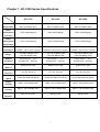
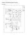
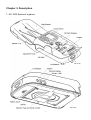
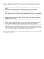
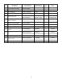
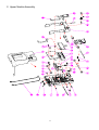
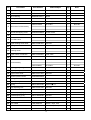
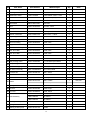
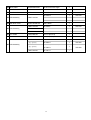
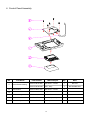
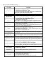
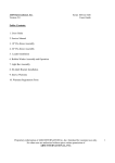
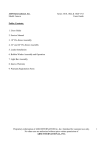
Service Manual NC-1000 Series 1 Table of Contents Chapter 1. NC-1000 Series Specifications .................................................... P.3 Chapter 2. NC-1000 Series System Overview............................................... P.4 Chapter 3. Description.................................................................................... P.7 Chapter 4. Maintaining NC-1000 Series and Important Safety Precautions .................................................................................. P.8 Chapter 5. NC1000 series Part List................................................................ P.9 Chapter 6. Inspection Problems and Recovery.......................................... P.18 Chapter 7. Combination Key Description ................................................... P.20 Chapter 8. Sensor Calibration Process....................................................... P.21 Chapter 9. Simple Operation Instructions .................................................. P.23 2 Chapter 1. NC-1000 Series Specifications NC-1100 NC-1200 NC-1300 Power AC90~240V 50/60Hz./ AC90~240V 50/60Hz./ AC90~240V 50/60Hz./ Requirement MA Li-lon Battery pack MA Li-lon Battery pack MA Li-lon Battery pack 15W + 5W(Charging) 15W + 5W(Charging) 15W + 5W(Charging) 1.8W + 5W(Charging) 1.8W + 5W(Charging) 1.8W + 5W(Charging) External Folded – 240 x 138 x 67 (mm) Folded – 240 x 138 x 67 (mm) Folded – 240 x 138 x 67 (mm) Dimensions Unfolded – 428 x 138 x 110 (mm) Unfolded – 428 x 138 x 110 (mm) Unfolded – 428 x 138 x 110 (mm) 1.1Kg without Battery Pack 1.1Kg without Battery Pack 1.1Kg without Battery Pack 1.2Kg with Battery Pack 1.2Kg with Battery Pack 1.2Kg with Battery Pack Ambient Temperature 0° ~ 40° C Temperature 0° ~ 40° C Temperature 0° ~ 40° C Conditions Humidity 20% ~ 90% RH. Humidity 20% ~ 90% RH. Humidity 20% ~ 90% RH. Roller Friction Type Roller Friction Type Roller Friction Type 175 * 85 * 0.5 (mm) 175 * 85 * 0.5 (mm) 175 * 85 * 0.5 (mm) At least 250 Notes Per Minute At least 250 Notes Per Minute At least 250 Notes Per Minute Approx. 60 circulated notes Approx. 60 circulated notes Approx. 60 circulated notes Approx. 100 circulated notes Approx. 100 circulated notes Approx. 100 circulated notes MG, UV, IR, Color MG, IR, Color MG, IR, Color Power Consumption (in action) Power Consumption (ideal status) Weight Feed-out Method Applicable currencies Counting Speed Hopper Capacity Stacker Capacity Counterfeit Detection 3 Chapter 2. NC-1000 Series System Overview A. NC-1100 4 B. NC-1200 5 C. NC-1300 6 Chapter 3. Description 1. NC-1000 Series at a glance: (NC-1100) (NC-1100) 7 Chapter 4. Maintaining NC-1000 Series and Important Safety Precautions 1. 2. 3. 4. 5. 6. 7. 8. These products are exclusively for indoor usages only, do not use or install these products outdoor. Please check the adapter and power cord periodically to protect from any damages. The power source for NC-1000 Series is between AC 90V~240V, 50/60 Hz NC-1000 Series are very sensitive products. Miss-counting may occur if dirt, dust or any other foreign objects get stuck or cluttered the sensor. Avoid influencing the accuracy, the best for the units is clean the sensors and rollers once a day with the brush supplied or a dry, soft lint-free cloth. Keep NC-1000 Series away from magnets, activated cellular phones, electrical appliances, or speakers within 13 cm / 5 inch Please disconnect power adapter and remove battery when the machine left unused for a long time. To switch on the unit, press and hold the “Set” key until the Power on bar has run to the end. NC-1000 Series are designed for processing banknotes and these are compatible for multi-banknotes, such as USD, EUR, and other specified currencies. Please process the notes ought to be verified in all four orientations (“Head Up-Right”, “Head Reversed”, “Tail Up-Right” or “Tail Reversed”) when doubtful notes appeared. Process result may be varied due to minting quality and circulation of different currencies which cause reject and alarm. 【Advice】When the suspicious note is detected, please reprocess it and confirm the reason of the alarm (MG, UV, or IR Error). 8 Chapter 5. Part List 1. Total Assembly 9 No Part Name Part Number Material/Spec Qty Note 1 Lower Module Assembly S-CNC1100AB1 1 2 Upper Modules Assembly S-CNC1100AB2 1 3 Bronze Bearing TPNC1100042500 Bronze 2 4 Upper Module shaft TPNC1100031500 SUS-303 1 5 Side Cover(Front) PPNC1100041100 ABS 94V0 1 NC1100 PPNC1100042100 ABS 94V0 - Black 1 Nc1200/NC1300 6 Side Cover(Rear) PPNC1100051100 ABS 94V0 1 NC1100 PPNC1100052100 ABS 94V0 - Black 1 Nc1200/NC1300 7 Bottom Cover Assembly S-CNC1100AD1 8 φ3*10 self tapping screw SC30010T01NR00 Round, Nickel 6 9 Spring SPNC1100081450 φ0.3 /φ3*8.6L 1 10 Hopper S-CNC1200AD1 ABS 94V0 1 NC1100 S-CNC1200AF1 ABS 94V0, Silver 1 Nc1200/NC1300 11 Lid PPNC1100031100 ABS 94V0 1 NC1100 PPNC110003C100 ABS 94V0 - Gray 1 NC1200/NC1300 12 LOGO Plate NPNC11002AL100 0.5t Aluminum 1 13 Version Label NPNC1100402000 0.1t Sticker 1 NC1100 STNC1300000S1A 0.1t Sticker 1 NC1200/NC1300 14 Extension Hopper PPNC1200052100 increase capacity 1 1 10 2. Upper Module Assembly 11 No Part Name Part Number Material/Spec Qty Note 1 Upper housing PPNC110002220A PC+ABS Black, flat 1 2 Shaft TPNC1100051500 SUS-303 1 3 Micro Bearing BE0623ZZ100410 623ZZ 4 4 Spring SPNC1100091450 SUφ0.4×φ4.8×10 2 5 IR Lens PPNC110021D400 Clear Acrylic 2 S-BNC1101A02 NC1100-C 1 NC1100 S-BNC1100A03 NC1200-C 1 NC1200 S-BNC1200A03 NC130X-C 2 NC1300 6 MR Sensor PCB Assembly 7 φ2.6*6 self tapping screw SC26006T02NR00 Round, Nickel 7 8 White Glass GLA03502030C00 35*20*3mm with 2 9 UV LED Frame PPNC1100192600 POM, black. 2 NC1100 PPNC1100192800 POM, Black. 2 NC1200/NC1300 10 Upper feeding wheel shaft TPNC1100081500 SUS-303 1 11 Spring SPNC1100021450 SUφ0.35×φ4.8×10 2 12 Feeding wheel S-CNC110A04 1 NC1100 RPNC1100087100 2 NC1200/NC1300 13 Upper sensor conduction TPNC1100075600 POM, white 4 14 Upper sensor conduction TPNC1100061500 SUS-303 1 S-BNC1101A03 NC1100-D 1 NC1100 S-BNC1100A04 NC1200-D 1 NC1200 S-BNC1300A01 NC1300-D 1 NC1300 16 Upper gap adjusting rack MPNC1100010200 1.5t SUS304 1 17 Gap adjusting board MPNC1100030200 1.5t SUS304 1 18 Upper Tenon shaft TPNC1100111500 SUS-303 1 19 M2.6*6 machine screw SC26006M05NF00 20 Spring, Extension SPNC1100012450 SUS-WH 2 21 Gap adjusting Screw TPNC1100142500 Bronze 1 22 Spring SPNC1100041450 SUφ0.6×三×14 1 23 Gap adjusting rack TPNC1100121500 SUS-303 1 24 M3.0*3 machine screw SC30003M05B040 Plate, black, Hex 1 25 Twisted Spring (Right) SPNC1100073450 SUS-WH 1 26 Twisted Spring (Left) SPNC1100063450 SUS-WH 1 27 Metal Guide SPNC1100051450 SUS-WH 1 28 Push Bottom PPNC1100171100 ABS 94V0 1 29 FCC Cable C18AF18BF155 155mm, 18pin, 0.5P 1 30 FCC Cable C18AF18BF155 155mm, 18pin, 0.5p 1 31 Control Panel assembly S-CNC1100AD2 15 PCB Assembly 4 1 12 3. Lower Modules Assembly 13 No Part Name Part Number Material/Spec Qty Note 1 Lower Housing PPNC110001222A PC+ABS 94V0 1 2 Feeding rubber wheel RPNC1100017100 Semi Clear – Yellow 1 3 Distribution wheel S-CNC1100A08 Front Rubber wheel + Gear 1 4 Rubber Belt LB035007040300 φ35×0.7×4w(NBR) 2 5 Distribution wheel S-CNC1100A09 Rear Rubber wheel + Gear 1 6 Gear Shaft TPNC1100011500 SUS-303 1 7 Gear PPNC11003616A0 HYTREL, white 2 8 E-ring WA030706SX7100 φ3 15 9 M2.6×6 Machine Screw SC26006M05NW00 Round, plate, w/2 washers. 1 10 Sensor conduction RPNC1100057100 Semi Clear – Yellow 2 11 Outputting wheel RPNC1100047100 Semi Clear – Yellow 1 12 Micro Bearing BEMR74ZZ070310 MR74ZZ 12 13 Gear for feeding PPNC1100261600 POM- white 1 14 Single Direction Bearing BEFC4KXX080610 FC4K 5 15 Gear for distributing PPNC1100271600 POM- white 1 16 MXL Drive Belt PPNC1100301600 POM- white 2 17 MXL Drive Belt PPNC1100291600 POM- white 1 18 Drive Belt LB155MXL032100 155MXL×3.2w 1 19 Drive Belt LB050MXL032100 50MXL×3.2w 1 20 Belt pressing frame MPNC1100050200 1.0 t SUS304+φ4SUS303 1 21 Belt pressing frame TPNC1100025600 POM- white 1 22 φ3×10 self tapping SC30010T01NR00 Round, nickel plated 4 23 DC Motor Assembly DMNC1100M20608 6V×7.6W×7200N 1 24 Encoder film PPNC1100242100 ABS – Black 1 25 Gear Bracket MPNC1100060200 SUS303+PU 1 26 M2.6×8 Machine Screw SC26008M05NW00 Round, plated, w/2 washers. 2 PPNC1100101100 ABS - Cream 1 NC1100 PPNC110010C100 ABS - Gray 1 NC1200/NC1300 28 Spring SPNC1100091450 SUS-WH 1 29 IR Lens PPNC110021D400 Clear Acrylic 2 30 IR Cover PPNC1100222800 POM - Black 2 S-BNC1100A05 NC1100-E S-BNC1200A05 NC1200-E S-BNC1200A05 NC1300-E 32 Bearing sustain perch PPNC1100131100 ABS – Cream 2 33 Spring SPNC1100021450 SUS-WH 4 34 Bearing sustain perch PPNC1100121100 Cream 4 27 Button 31 PCB Assembly 14 1 35 White Glass GLA03502030C00 35×20×3mm with Angle 2 36 UV LED Frame PPNC1100192800 POM – Black 2 37 Front Dust Cover PPNC1100322100 ABS - Black 1 NC1100-G 1 NC1100 NC1200-G 1 NC1200 NC1300-G 1 NC1300 PPNC1100332100 ABS - Black 1 S-BNC1101A04 NC1100-F 1 NC1100 S-BNC1300A02 NC1200-F 1 NC1200 S-BNC1300A02 NC1300-F 1 NC1300 41 FCC Cable C18AF18BF037 37mm,18pin,0.5p 1 42 FCC Cable C06AF06BF037 37mm, 6pin, 1p 1 S-BNC1101B01 NC1100-A 1 NC1100 S-BNC1200A01 NC1200-A 1 NC1200 38 PCB Assembly 39 Rear Dust Cover 40 PCB Assembly 43 PCB Assembly S-BNC1101A07 S-BNC1200A01 S-BNC1301A01 NC1300-A, NC1302-A, NC1304-A NC1301-A 15 1 1 NC1300 4. Control Panel Assembly No Part Name Part Number Material/Spec Qty Note PPNC11001611B0 ABS 94V0 – Cream 1 NC1100 PPNC110016C1B0 ABS - Gray 1 NC1200/NC1300 Push Buttons PPNC11002311A0 ABS 94V0 – Cream 1 3 Control Panel Plate NPNC11003PC000 0.3t pc 1 4 PCB Assembly S-BNC1100A02 NC1100-B 1 5 FCC Cable C18AF18BF155 155mm,18pin,0.5p 1 6 φ2.6×6 Phillips Screw SC26006T02NR00 Nickel plated 5 1 Control Panel Housing 2 16 7202 5. Bottom Cover Assembly No Part Name 1 Bottom Cover 2 Battery Cover 3 Sponge 4 Stand (Left) 5 Stand (Right) 6 Self Adhesive 7 Spec Plate Part Number Material/Spec Qty Note PPNC110006C100 ABS – Cream 1 NC1100 PPNC1100062100 ABS - Black 1 NC1200/NC1300 PPNC110007C100 ABS 94V0 – Cream 1 NC1100 PPNC1100072100 ABS 94V0 - Black 1 NC1200/NC1300 DT05001403SP10 Self Adhesive50×14×3T 1 PPNC110008C100 ABS – Cream 1 NC1100 PPNC1100082B00 ABS - Black 1 NC1200/NC1300 PPNC110009C100 ABS – Cream 1 NC1100 PPNC1100092B00 ABS - Black 1 NC1200/NC1300 OCRNC110001200 Rubber 10×3.0×0.8t, black 4 NPNC1100301000 0.15t Polyester 1 NC1100 NPNC11004PC00 0.254t Polyester 1 NC1200/NC1300 17 Chapter 6. Inspection problems and Recovery A. Operating Problem Display and Operating Errors Phenomenon Treatment When turn on the unit, no indication on LCD, either the buzzer can not be heard 1. Is the power cord connected properly? 2. Please check the adapter is specially supplied 10V/24W by MA. 3. If you can turn on the machine with a fully charged battery, please replace the breakdown adapter. 4. Remove the battery, connect with a functional adapter then turn on the machine again. * If you followed the steps as the above-mentioned and the unit still can not boot up, please contact with MA. No display on LCD 1. Is the power cord plugged in? 2. Reboot machine to re-start LCD.. Unclear display on LCD Reboot machine to re-start LCD. No Backlight 1. To turn the backlight in setting menu (Backlight Setting) 2. LED is damaged, please contact with MA. Low battery 1. Charge the battery. 2. Replace the battery. Hopper Error 1. Foreign matter is left in the hopper. 2. Foreign matter is left in the bill path. * If there is any question after, please contact with MA. Key malfunction To enter the “Self diagnosis test” mode, and check on the key. * If there is any question, please contact with MA. Counting Errors Phenomenon Error occurs often Denomination misread Value Error IR/UV Treatment 1. Turn the thickness adjustment dial to the anti-clockwise rotation (left-handed) to make the space wider. 2. Do Calibration. 3. Please record the information of the error banknote by “Sample Tool” and sending these sampling data to MA. May caused by index mismatch, please update PCSuite again 1. Please check the note path for any matter left in the bill path and obstructed the IR/UV Sensor. 2. To clear the bill path. 3. Adjust the Sensor; please refer to “Calibration Process”. *If there is any question after adjustment, please contact with MA. 18 B. Error Code and Processing: Error Code Paper Jam Double Dimension Error Treatment 1. Adjust thickness in the transport path. 2. Please reduce the banknote on the hopper. 3. Please check is there any foreign matter in the bill path or transmission gear. * If there is any question after, please contact with MA. Two bills were fed at same time. If the note on the top of stacker is a genuine note however has been rejected. Turn the thickness adjustment knob clockwise and test again MG Error 1. The suspicious note’s MG is different to genuine note. 2. Please confirm the suspicious note. * If there is MG Error (the suspicious note is genuine), please sample the note by “MA PCSuite” and send the sampling data to MA. UV Error 1. The suspicious note’s UV is different to genuine note. 2. Please confirm the suspicious note. * If there is UV Error (the suspicious note is genuine), please sample the note by “MA PCSuite” and send the sampling data to MA. IR Error 1. The suspicious note’s IR is different to genuine note. 2. Please confirm the suspicious note. * If there is IR Error (the suspicious note is genuine), please sample the note by “MA PCSuite” and send the sampling data to MA. Wrong denomination Bill path error Bill path error – IR Bill path error –UV At the SORT mode, the banknote in different denomination to the first genuine note is detected. Please confirm the Trigger of hopper or the first Trigger of bill path without foreign matter. If the bill path is clear, nothing on the IR sensors, please calibrate the unit. If the bill path is clear, nothing on the UV and Color sensors, please calibrate the unit. Motor Error 1. Please note does motor error always occur when power on. 2. Confirm if there is any problem of the Encoder. * If the motor does not turn at power on, please contact with MA Wrong Face At the FACE mode, the banknote in same denomination but different face to the first genuine note is detected. Wrong Orientation EEPROM Error UART Error Print Error At the ORNT mode, the banknote in same denomination but different orientation to the first genuine note is detected. Component breakdown please sent back it to MA and replace it. The flat cable has loosened, please sent it back to MA. 1. 2. 3. 4. Please check the position and the paper box. Please check the power supply system. Does the printer cable plug in properly? The printer port may lose contact, please sent it back it to MA. 19 Chapter 7.Combination Key Description Combination Key Combinaiton Set + CUR + Start Set + C + Start Denomination Use QC_CALIBRATION_KEY Adjust Sensor. QC_SIMPLE_KEY Calibration process. Check the machine’s information, such as the Set + F1 + Start SHOW_VER_KEY firmware version, serial number and manufacturing date. Set + F1 + Batch + Start Set + ADD + M/A Set + ADD + DET + F2 UPDATE_LD_KEY To update the boot loader. SET_DET_PAGE_USE_KEY Set to disable/enable FACE and ORNT mode SET_MOTOR_KEY Motor self check and speed adjustment 20 Chapter 8. Sensor Calibration Process 1. Plug in the adaptor power cord, and connect the DC jack to NC-1000 Series. 2. While the initializing, press the function keys “Cur” and “Start” together and hold until the display shows the number 1~17 (NC-1100)/1~23 (NC-1200, NC-1300)(see below) 1 2 3 4 5 6 7 8 9 10 11 12 13 14 15 16 17 1 2 3 4 5 6 7 8 9 10 11 12 13 14 15 16 17 18 19 20 21 22 23 (NC-1200/NC-1300) (NC-1100) 3. 1 ~ 17/ 1~23 stand for different sensors. 4. Feed the exclusive calibration paper supplied by MA, NC-1000 Series start to calibrate automatically. 5. While calibrating the unit, will see as below: 2 1 2 3 4 5 6 7 8 9 10 11 12 13 14 15 16 17 1 2 3 4 5 6 7 8 9 10 11 12 13 14 15 16 17 18 19 20 21 22 23 (NC-1100) 6. Repeat step 4~5, until the display shows “OK” (as below). (NC-1200/NC-1300) OK 7. If the display shows the stroke circle appears continuously, it means the sensor out of range (see below). Please check on the Sensor (such as the wrong position, Emitter malfunction or Receiver dusted) 1 2 3 4 5 6 7 8 9 10 11 12 13 14 15 16 17 1 2 3 4 5 6 7 8 9 10 11 12 13 14 15 16 17 18 19 20 21 22 23 (NC-1100) (NC-1200/NC-1300) 8. To detect whether any foreign matter left in the bill path: a. Open the Lid, and covered IR and UV Sensor with a piece of paper. b. Turned on the NC-1100. c. NC-1100 will buzz three short beeps when you turned on. It is abnormal if there is no sound. 21 *Sensors position NC-1100 Sensor No. Detection Corresponding Assembly NO. PCB Assembly Part number 1~2 MG Upper Modules Assembly 6 NC1100-C S-BNC1101A02 3~5 Color Upper Modules Assembly 15 NC1100-D S-BNC1101A03 6 UV Lower Modules Assembly 40 NC1100-F S-BNC1101A04 IR Emitter Upper Modules Assembly 6 NC1100-C S-BNC1101A02 IR Receiver Lower Modules Assembly 31 NC1100-E S-BNC1100A05 Upper Modules Assembly 15 NC1100-D S-BNC1101A03 Lower Modules Assembly 40 NC1100-F S-BNC1101A04 7~9 10 ~ 11 14 ~ 15 12~13 IR Reflect 16~17 NC-1200 Sensor No. Detection Corresponding Assembly NO. PCB Assembly 1~4 MG Upper Modules Assembly 6 NC1200-C S-BNC1100A03 Upper Modules Assembly 15 NC1200-D S-BNC1100A04 Lower Modules Assembly 40 NC1200-F S-BNC1300A02 Lower Modules Assembly 31 NC1200-E S-BNC1200A05 Upper Modules Assembly 15 NC1200-D S-BNC1100A04 Lower Modules Assembly 40 NC1200-F S-BNC1300A02 TIR Lower Modules Assembly 31 NC1200-E S-BNC1200A05 Sensor No. Detection Corresponding Assembly NO. PCB Assembly Part number 1~4 MG Upper Modules Assembly 6 NC1300-C S-BNC1100A03 Upper Modules Assembly 15 NC1300-D S-BNC1100A01 Lower Modules Assembly 40 NC1300-F S-BNC1300A02 Lower Modules Assembly 31 NC1300-E Upper Modules Assembly 15 NC1300-D S-BNC1100A01 Lower Modules Assembly 40 NC1300-F S-BNC1300A02 Lower Modules Assembly 31 NC1300-E 5~6 7~8 RIR 15 ~18 9 10 11~14 19~22 Color Part number NC-1300 5~6, 23~26 7~8, RIR 27~29 15 ~18 9, 30 10, 31 11~14 19~22 Color TIR 22 S-BNC1200A05 S-BNC1200A05 Chapter 9. Simple Operating Instructions 1. To operate the device smoothly, please follow below instructions: A. Avoid processing wet, excessively dirty or spoiled notes. B. Remove notes been folded or heavily curled. C. Check for foreign matter mixed with notes, i.e.: paper shreds, rubber, clips, dust, etc. 2. Placing Bills A. Spread and separate newly printed notes well; some of them are slightly adhesive. B. Align all the corners and edges of the notes, improper operation may cause process errors. C. Put the notes along the lower side of the bill path to prevent false alarms. D. Slightly adjust the gap adjustment knob depending on condition of the notes. Recommended to keep the knob position between 11 o’clock to 1 o’clock. 3. Operating and Setting NC-1000 Series, 1.1 Plug in the adaptor power cord, and connect the DC jack to NC-1000 Series. Press and hold the “Set” key until the Power bar runs to the end. 1.2 Place the notes on the hopper, NC-1000 Series keep running until the last note, in the mean time, if a suspicious note is detected, the equipment will stop, by giving three short beeps while displaying “Suspicious note – (reason: i.e. MG-Magnetic, UV-Ultraviolet, IR-Infrared). Check the note, and press “C” to clear the status. Press “Start” to continue counting. The result will be shown on the LCD as amount and number of notes. 1.3 Connect the printer and the Print icon lights up at the right bottom of the panel. Press the navigation key to print the counting result. 1.4 Function Keys Add: Switch the Add Mode on; the counting of notes will be accumulated automatically. The display will show the icon “=”. Auto: Switch between Auto Mode and Manual Mode. When “Auto” mode is on, the display shows “A” and the unit will start counting automatically; oppositely, when the “Manual” mode is on and the display shows “M”, it is necessary to start counting by pressing “Enter/Start” key. Cur: Select preferred currency to start counting. 23