1
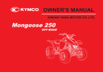
MXU 500 / MXU 500 IRS
ATV off road
Do not remove this Owner’s Manual from the vehicle. Read this
manual carefully before operating the vehicle as it contains
important safety information.
Owner’s Manual
C 2008 KYMCO. All rights reserved. Printed in Taiwan. www.kymco.com
Version:T200-LAAOCA-US-A5
IMPORTANT NOTICES
READ THIS MANUAL CAREFULLY
Your Owner's Manual contains important information on safety, operation, and
maintenance. Any one who operates this ATV should carefully read and
understand the contents of this manual before riding the vehicle.
AGE RECOMMENDATION
The minimum recommended age for this ATV model is 16. Children under age 16
should never operate this vehicle.
RIDER TRAINING
Anyone who operates this vehicle should get proper instruction.
FOR OFF-ROAD USE ONLY
This vehicle is designed and manufactured for off-road use only. This machine is
designed and manufactured for OFF-ROAD use only. It is illegal and unsafe to
operate this machine on any public street, road or highway.
This machine complies with all applicable OFF-ROAD noise level and spark
arrester laws and regulation in effect at the time of manufacture.
Please check your local riding laws and regulations before operating this
machine.
A
SPECIAL MESSAGES
KYMCO provides many important safety messages both in this manual and on the
vehicle. For your safety and the safety of others, pay special attention to all
warnings preceded by this alert symbol . Failure to follow the warnings
contained in this manual can result in SERIOUS INJURY or DEATH.
WARNING
Indicates a strong possibility that serious injury or death may
result if instructions are not followed.
CAUTION
Indicates a possibility that equipment or property damage
could result if instructions are not followed.
Note:
Gives helpful information
The Owner's Manual should be considered a permanent part of your ATV. It should
remain with the vehicle at all times and stay with the ATV if it is sold.
B
PREFACE
Congratulations on your purchase of the KYMCO ATV. KYMCO take pride in a
worldwide reputation for quality-in research, design, production and service.
For replacement parts and accessories, we recommend genuine KYMCO
products. They've been specially designed for your vehicle and manufactured to
meet KYMCO's demanding standards.
This manual will provide you with a good basic understanding of the features and
operation of this machine. This manual includes important safety information. It
provides information about special techniques and skills necessary to ride your
machine. It also includes basic maintenance and inspection procedures. If you
have any questions regarding the operation or maintenance of your machine,
please consult a KYMCO dealer.
We wish you many years of safe and enjoyable riding.
While reading this manual, remember:
WARNING
Indicates a strong possibility that serious injury or death may
result if instructions are not followed.
All information in this publication is based on the latest product information
available at the time of approval for printing. KWANG YANG MOTOR CO.,LTD
Reserves the right to make changes at any time without notice and without
incurring any obligation.
C
CONTENTS
Page
Page
LOCATION OF THE WARNING AND
CONTROL FUNCTIONS ....................16
IGNITION SWITCH..............................16
SPECIFICATION LABELS ...................1
INSTRUMENTS AND INDICATOR........17
Multi-function display.......................19
HANDLEBAR SWITCHES....................26
SAFETY INFORMATION ......................4
Headlight dimmer switch..................26
Start button.....................................26
Engine stop switch...........................27
Passing signal switch.......................27
DESCRIPTION AND MACHINE
IDENTIFICATION ..................................9
RIGHT HANDLEBAR SWITCH.............28
2WD/4WD select switch....................28
IDENTIFICATION NUMBER
RECORDS...........................................9
KEY IDENTIFICATION NUMBER............9
FRAME SERIAL NUMBER...................10
ENGINE SERIAL NUMBER..................10
PARTS LOCATION.............................11
RECOIL STARTER..............................29
THROTTLE LEVER.............................30
SPEED LIMITER.................................31
(Cont'd)
D
Page
Page
FRONT BRAKE LEVER.......................32
PRE-OPERATION CHECKS.. ...........43
REAR BRAKE LEVER..........................32
DRIVE SELECT LEVER ......................44
Drive select lever adjustment............46
FRONT AND REAR BRAKES................48
FUEL...............................................49
DRIVE SHAFT BOOTS........................50
ENGINE OIL ......................................51
FINAL GEAR OIL................................52
DIFFERENTIAL GEAR OIL..................52
THROTTLE LEVER.............................53
FITTINGS AND FASTENERS...............53
LIGHTS..............................................53
SWITCHES.........................................53
TIRES................................................54
How to measure tire pressure ..............55
Tire wear limit ....................................56
COOLANT..........................................56
BRAKE PEDAL...................................32
PARKING BRAKE...............................33
DRIVE SELECT LEVER.......................34
FUEL TANK CAP ................................35
FUEL VALVE......................................35
CHOKE KNOB....................................37
ACCELERATING PUMP LEVER .........38
SEAT..................................................39
FLAG POLE BRACKET.......................40
TRAILER HITCH.................................40
OWNER’S MANUAL STORAGE
COMPARTMENT.................................41
ACCESSORY SOCKET........................42
(Cont'd)
E
Page
Page
OPERATION ........................................58
RIDING YOUR ATV ............................71
STARTING A COLD ENGINE...............58
Using the recoil starter......................61
STARTING A WARM ENGINE..............62
WARMING UP.....................................62
DRIVE SELECT LEVER OPERATION
AND REVERSE DRIVING ....................63
Shifting: neutral to high
and high to low .................................63
Shifting: neutral to reverse
and reverse to park...........................64
ENGINE BREAK-IN.............................65
GETTING TO KNOW YOUR ATV .........72
RIDE WITH CARE AND GOOD
JUDGEMENT......................................73
APPAREL...........................................75
PRE-OPERATION CHECKS................79
Speed limiter...................................80
LOADING AND ACCESSORIES..........81
Load Limits......................................81
Loading and operational guidelines...81
Accessories.....................................82
MODIFICATIONS................................83
No modifications..............................83
EXHAUST SYSTEM............................84
BE CAREFUL WHERE YOU RIDE........85
FOR OFF-ROAD USE ONLY.................90
DURING OPERATION.........................92
TURNING YOUR ATV ..........................94
SLIDING AND SKIDDING....................96
CLIMBING UPHILL.............................98
PARKING..........................................66
Parking on a slope............................67
ACCESSORIES ..................................68
LOADING ...........................................69
(Cont'd)
F
Page
Page
RIDING DOWNHILL.......................104
PERIODIC MAINTENANCE AND
ADJUSTMENT ...................................113
CROSSING A SLOPE.........................106
TOOL KIT/
TOOL KIT COMPARTMENT.................113
PERIODIC MAINTENANCE/
LUBRICATION..................................115
ENGINE OIL ......................................118
FINAL GEAR OIL...............................125
DIFFERENTIAL GEAR OIL.................127
SPARK PLUG INSPECTION..............129
SPARK ARRESTER...........................130
AIR FILTER CLEANING.....................132
AIR CLEANER HOUSING DRAIN
TUBE...............................................135
IDLE SPEED ADJUSTMENT .............136
THROTTLE LEVER ADJUSTMENT....137
VALVE CLEARANCE ADJUSTMENT..138
FRONT BRAKE PADS INSPECTION...138
REAR BRAKE PADS INSPECTION.....139
BRAKE FLUID INSPECTION..............139
RIDING OVER ROUGH TERRAIN.......108
CROSSING THROUGH SHALLOW
WATER........................................109
PA R K I N G . . . . . . . . . . . . . . . . . . . . . . . . . . . . . . . . . . . . 11 0
WHAT TO DO IF..................................111
WHAT TO DO....................................111
(cont'd)
G
Page
Page
COOLING SYSTEM INSPECTION......141
Engine overheating........................143
CLEANING AND STORAGE ...........153
WHEEL REMOVAL............................144
B. STORAGE ....................................155
A. CLEANING ...................................153
WHEEL INSTALLATION.....................144
BATTERY..........................................146
SPECIFICATIONS..................................157
Battery remove..............................147
Battery installation.........................147
NOISE REGULATION.............................161
FUSE REPLACEMENT......................148
HEADLIGHT BEAM ADJUSTMENT....149
MAINTENANCE RECORD.......................162
DRIVE SHAFT BOOTS.......................149
CABLE INSPECTION AND
LUBRICATION..................................150
INDEX...................................................163
TROUBLESHOOTING .......................151
Troubleshooting chart...................152
H
LOCATION OF THE WARNING AND
SPECIFICATION LABELS
WARNING INFORMATION
Anyone who rides the vehicle should read and understand this information before riding. They
contain important information for safe and proper operation of your ATV.
The labels should be considered as permanent parts of the vehicle. If a label comes off or becomes
hard to read, contact your KYMCO dealer for replacements.
(A) (US version only)
(1)
(3) (4)
(2)
(5)
/ MXU 500 IRS
(B) (US version only)
(B)
(7)
1
(A) (6)-a or (6)-b
(8)
(1)
(3)
WARNING
Never carry passenger on
This carrier.
Maximum load:45 Kg (100 lbs)
(2)
(5)
WARNING
WARNING
NEVER ride as a
passenger.
Passengers can cause a
loss of control, resulting
in SEVERE INJURY or
DEATH.
Never carry passenger on
This carrier.
Maximum load:85 Kg (187 lbs)
(6)-a(MXU 500)
(4)
CAUTION
Before shifting, you must stop the machine and
return the throttle lever to its closed position until
the engine speed to the specified idling speed.
Otherwise, the transmission may be damaged .
2
(7)
(6)-b(MXU 500 IRS)
WARNING
Improper tire pressure or overloading
can cause loss of control.
Loss of control can result in severe
injury or death.
Cold tire pressure:
Front: 5.0 psi ( 35 kPa)
Rear: 4.5 psi ( 32 kPa)
Maximum weight capacity: 485 lbs
( 220 kg)
87505-LFE9-M35
(8)
WARNING
Exceeding vehicle towing limit could lead to an
accident. Reduce speed when towing a trailer.
Read owner's manual for details.
MAXIMUM TOWING CAPACITY: 454kg (1000lbs)
TONGUE WEIGHT: 16kg (35 lbs)
SAFETY INFORMATION
AN ATV IS NOT A TOY AND CAN BE HAZARDOUS TO OPERATE. An ATV handles differently from
other vehicles including motorcycles and cars. An accident can occur quickly, even during routine
maneuvers such as turning and riding on hills or over obstacles, if you fail to take proper precautions.
SEVERE INJURY OR DEATH can result if you do not follow these instructions:
Read this manual and all labels carefully and follow the operating procedures described.
Never operate an ATV without proper training or instruction.
Beginners should receive training from a certified instructor.
Always follow the age recommendation:
- A child under 16 years old should never operate an ATV with engine size greater than 90cc.
Never carry a passenger on an ATV.
Always avoid operating an ATV on any paved surfaces, including sidewalks, driveways, parking
lots and streets.
Never operate an ATV on any public street, road or highway, even a dirt or gravel one.
4
Never operate an ATV without wearing an approved motorcycle helmet that fits properly. You
should also wear eye protection (goggles or face shield), gloves, boots, long-sleeved shirt or
jacket, and long pants.
Never consume alcohol or drugs before or while operating this ATV.
Never operate at speeds too fast for your skills or the conditions. Always go at a speed that is
proper for the terrain, visibility and operating conditions, and your experience.
Never attempt wheel, jump, or other stunt.
Always inspect your ATV each time you use it to make sure it is in safe operating condition. Always
follow the inspection and maintenance procedures and schedules described in this manual.
Always keep both hands on the handlebars and both feet on the footboards of the ATV during
operation.
Always follow proper procedures for turning as described in this manual. Practice turning at low
speeds before attempting to turn at faster speeds. Do not turn at excessive speed.
Never operate on excessively rough, slippery or loose terrain until you have learned and practiced
the skills necessary to control the ATV on such terrain. Always be especially cautious on these
kinds of terrain.
Always go slowly and be extra careful when operating on unfamiliar terrain. Always be alert to
changing terrain conditions when operating the ATV.
5
Always follow proper procedures for climbing hills as described in this manual. Check the terrain
carefully before you start up any hill. Never climb hills with excessively slippery or loose surfaces.
Shift your weight forward. Never open the throttle suddenly. Never go over the top of a hill at high
speed.
Always follow proper procedures for going down hills and for braking on hills as described in this
manual. Check the terrain carefully before you start down any hill. Shift your weight backward.
Never go down a hill at high speed. Avoid going down hill at an angle that would cause the vehicle
to lean sharply to one side. Go straight down the hill where possible.
Always follow proper procedures for crossing the side of a hill as described in this manual. Avoid
hills with excessively slippery or loose surfaces. Shift your weight to the uphill side of the ATV.
Never attempt to turn the ATV around on any hill until you have mastered the turning technique
described in this manual on level ground. Avoid crossing the side of a steep hill if possible.
Never operate the ATV on hills too steep. Practice on smaller hills before attempting larger hills.
Always use proper procedures if you stall or roll backwards when climbing a hill. To avoid stalling,
maintain a steady speed when climbing a hill. If you stall or roll backwards, follow the special
procedure for braking described in this manual. Dismount on the uphill side or to a side if pointed
straight uphill. Turn the ATV around and remount, following the procedure described in this
manual.
6
WARNING
POTENTIAL HAZARD
Improper handling of gasoline.
WHAT CAN HAPPEN
Gasoline can catch fire and you could be
burned.
HOW TO AVOID THE HAZARD
Always turn off the engine when refueling.
Do not refuel right after the engine has been
running and is still very hot.
Do not spill gasoline on the engine or exhaust
pipe/muffler when refueling.
Never refuel while smoking, or while in the
vicinity of sparks, open flames, or other
sources of ignition such as the pilot lights of
water heaters and clothes dryers.
When transporting the machine in another
vehicle, be sure it is kept upright and that the
fuel cock is in the "OFF" position.
Otherwise, fuel may leak out of the carburetor
or fuel tank.
WHAT CAN HAPPEN
Gasoline is poisonous and can cause injuries.
HOW TO AVOID THE HAZARD
If you should swallow some gasoline or inhale
a lot of gasoline vapor, or get some gasoline in
your eyes, see your doctor immediately.
If gasoline spills on your skin, wash with soap
and water. If gasoline spills on your clothing,
change your clothes.
7
WARNING
ON
POTENTIAL HAZARD
Starting or running the engine in a closed
area.
WHAT CAN HAPPEN
Exhaust fumes are poisonous and may
cause loss of consciousness and death
within a short time.
HOW TO AVOID THE HAZARD
Always operate your machine in an area
with adequate ventilation.
8
DESCRIPTION AND MACHINE IDENTIFICATION
KEY IDENTIFICATION NUMBER
The key identification number is stamped on
the hang tag as shown in the following
illustration.
IDENTIFICATION NUMBER RECORDS
Record the key identification number, frame
serial number, engine serial number and
model code information for assistance when
order replacement parts.
KEY NO.
FRAME NO.
ENGINE NO.
(1)
MODEL CODE
(1) Key identification number
9
FRAME SERIAL NUMBER
The frame serial number is stamped on the
front and rear of the frame.
ENGINE SERIAL NUMBER
The engine serial number is stamped on the left
crankcase.
(1)
(1)
(1) Engine serial number
(1) Frame serial number
10
PARTS LOCATION
(03)
(02)
(02)
(01)
(01) Rear brake lever
(02) Headlights/Position lights
(03) Front brake lever
11
(04) (07)
(06)
(05) (04)
(04) Taillights/Brake lights
(05) 2WD/4WD select switch and differential lock lever
(06) Instrument and indicators
(07) Headlight dimmer switch
Starter button
Engine Stop Switch
Passing signal switch
(08) Spark arrester
(09) Trailer hitch (MXU 500 version only)
(10) Throttle lever
(10)
(09)
(08)
MXU 500 IRS selectivity appurtenances
(09)
12
(23)
(22)
(21) (20)
(19)
(19) Exhaust system
(20) Battery/Fuse
(21) Tool kit
(22) Accelerating pump lever
(23) Rear brake fluid reservoir
(24) Accessory socket seat
(25) Drive select lever
(24)
(25)
14
(15) (14)(13)
(12) (11)
(11) Reservoir water tank
(12) Front brake fluid reservoir
(13) Fuel valve
(14) Recoil starter
(15) Seat
(16) Brake pedal fluid reservoir
(17) Seat lock lever
(18) Oil level inspection window
(16)
(17)
(18)
13
(30)
(29) (28) (27)
(26)
(26) Right footpeg
(27) Owner’s manual storage
(28) Front cargo rack
(29) Ignition switch
(30) Left footpeg
(31) Rear cargo rack
(32) Fuel fill cap
(33) Choke knob
(34) Rear brake pedal
(35) Flag pole bracket
(36) Tool storage(MXU 500 IRS version only)
NOTE:
The machine you have purchased may differ
slightly from those shown in the figures of this
manual.
(31)
(32)
(33) (34)
(35) (36)
15
CONTROL FUNCTIONS
IGNITION SWITCH
Functions of the respective switch positions
are as follows:
ON
OF
F
(1)
OFF:
All electrical circuits are switched off . The key
can be removed in this position.
ON :
All electrical circuits are switched on.
The engine can be started.
The key can not be removed.
(2)
(1) Ignition switch
"
“:
The ignition switch is ON while the position
light and taillight will light.
All electrical circuits are switched on.
The engine can be started.
The key can not be removed.
16
(2) Key
INSTRUMENTS AND INDICATOR
(1) Multi-function display
The display includes the following functions:
Speedometer
Odometer/Tripmeter
Digital clock
2WD/4WD indicator
Fuel gauge
(1)
2WD
4WD
ODO
(2)
TRIP A B
mile
km PM
(3)
SET
MODE
P RN H L
(11)
(10)
(9) (8) (7) (6) (5)
(2) High beam indicator
The ignition switch is at the "
" position, the
high beam indicator will light when the headlight
switch to select High beam ( ).
(4)
(1) Multi-function display
(2) High beam indicator
(3) Coolant temperature warning indicator
(4) Set button
(5) Low-range indicator light “L”
(6) High-range indicator light “H”
(7) Neutral indicator light “N”
(8) Reverse indicator light “R”
(9) Park indicator light “P”
(10) Mode button
(11) Differential lock indicator(MXU 500 IRS version only)
17
(8) Reverse indicator light “R”
This indicator light comes on when the drive
select lever is in the “R” position.
(3) Coolant temperature warning indicator
When the coolant temperature reaches a
specified level, this indicator comes on to
warn that the coolant temperature is too hot.
If the indicator comes on during operation,
stop the engine as soon as it is safe to do so
and allow the engine to cool down for about
10 minutes.
(9) Park indicator light “P”
This indicator light comes on when the drive
select lever is in the “P” (park) position.
(10) Mode button
This button is used to select km/h, mph, km
and mile.
This button is also used to adjust the time
and reset the trip meter.
(4) Set button
This button is used to select ODO, TRIP A
and TRIP B.
This button is also used to adjust the time
and reset the trip meter.
(11)Differential lock indicator(MXU 500 IRS only)
The front axle is equipped with a lockable
differential that allows the operator to choose
between an open differential or a closed
differential in low traction situations.
Pulling the lock lever to the left.
To lock the differential on the 4WD, move the
4WD differential Button.
(5) Low-range indicator light “L”
This indicator light comes on when the drive
select lever is in the “L” position.
(6) High-range indicator light “H”
This indicator light comes on when the drive
select lever is in the “H” position.
(7) Neutral indicator light “N”
This indicator light comes on when the drive
select lever is in the “N” position.
18
Multi-function display
(3)
(2)
(1) Speedometer
Shows riding speed in km/h or mph.
(1)
2WD
4WD
ODO
Press and hold MODE button for more than 2
seconds to select mph or km/h.
TRIP A B
mile
km PM
(4)
2WD
4WD
(5)
ODO
TRIP A B
mile
km PM
SET
MODE
(1) Speedometer
(2) 2WD/4WD indicator
(3) Fuel gauge
(4) Odometer/Tripmeter
(5) Digital clock
P RN H L
19
(3) Fuel gauge
The fuel gauge shows the approximate fuel
supply available in a graduated display. The
normal operating fuel range is with the
section between the segment F and segment
E. When the segment E or the fuel indicator
(3) flashes, fuel will be low and you should
refill the tank as soon as possible.
(2) 2WD/4WD indicator
Shows the drive mode is in the 2WD or 4WD.
2WD
4WD
(2)
(1)
(3)
(1) Segment F
(2) Segment E
20
(3) Fuel indicator
(4) Odometer/Tripmeter
The odometer shows the total mileage in Km or in miles.
The tripmeter shows the trip distance in Km or in miles.
There are two tripmeters, tripmerer A and tripmeter B
Press and hold SET button for more than 2 seconds to select ODO, TRIP A or TRIP B.
Press and hold MODE button for more than 2 seconds to select mile or km.
2WD
4WD
ODO
2WD
4WD
TRIP A B
ODO
mile
km PM
mile
km PM
SET
MODE
TRIP A B
SET
MODE
P RN H L
P RN H L
ODO
TRIP A B
mile
km
21
To reset tripmeter:
1. Press and hold SET button for more than 2
seconds to select tripmeter A or tripmeter
B.
2. Press and hold both the MODE button and
SET button in the same time until the
tripmeter is reset.
2WD
4WD
2WD
4WD
TRIP A B
TRIP A B
mile
km PM
mile
km PM
SET
MODE
SET
MODE
P RN H L
P RN H L
TRIP A B
TRIP A
mile
km
mile
km
22
(5) Digital clock
Show the time (hours and minutes) while the
ignition is ON.
2WD
4WD
To adjust the time manually, proceed as follows:
1. Turn the ignition switch ON.
2. Press and hold SET button for more than 2
seconds to select ODO mode.
3. Press and hold both the MODE button and
SET button in the same time for more than 2
seconds. The clock will be set in the adjust
mode with the hour display flashing.
ODO
mile
km PM
SET
MODE
P RN H L
NOTE:
Digital clock can be adjust in ODO mode only,
never select TRIP A or TRIP B mode when you
want to adjust your digital clock.
PM
23
4. To set the hour, press the SET button until the
desired hour.
5. Press the MODE button, the minute display will
start flashing.
2WD
4WD
2WD
4WD
ODO
ODO
mile
km
mile
km
SET
MODE
SET
MODE
P RN H L
P RN H L
24
6. To set minute, press the SET button until the
desired minute.
7. To end the adjustment, Press both the MODE
button and SET button in the same time.
2WD
4WD
2WD
4WD
ODO
ODO
mile
km
mile
km
SET
MODE
SET
MODE
P RN H L
P RN H L
25
LEFT HANDLEBAR SWITCHES
(1)
(2)
(1) Headlight switch
(2) Starter button
Headlight dimmer switch
Turn the switch to the " " position to switch on
the low beam.
Turn the switch to the " " position to switch on
the high beam.
Turn the switch to the "" position to switch off
the headlight.
Stater button
To starter the engine, press the starter button,
with the transmission in neutral, the ignition
switch ON and the engine stop switch
At RUN ( )
CAUTION:
See starting instructions prior to starting
engine (see page 58 for details).
26
(4)
(3)
(3)Engine stop switch
(4) Passing signal switch
Engine stop switch
When the switch is in the RUN ( ) position, the
engine will operate. When the switch is in OFF
( ) position, the engine will not operate.
This switch is intended primarily as a safety or
emergency control, and it should normally
remain in the RUN ( ) position.
Passing signal switch
When passing, if there are cars coming from the
opposite direction, press and release the
passing signal switch and the headlight will wink
to warn the coming vehicles.
NOTE:
If you stop your ATV by turning the engine stop
switch OFF ( ), be sure to turn the ignition
switch OFF to prevent battery discharge.
27
RIGHT HANDLEBAR SWITCH
2WD/4WD select switch
This ATV is equipped with a 2WD/4WD select
switch, which permits a choice between the
“2WD” and “4WD” drive modes. Select a drive
mode that is suitable for your riding.
The 2WD/4WD select switch is located above
the throttle lever. To select the drive mode,
push the 2WD/4WD select switch to the
desired position.
(1)
(1) 2WD/4WD select switch(MXU 500)
To check your present drive mode, look at the
Multi-function display.
2WD
2WD mode
ODO
(1) 2WD/4WD
Select switch
TRIP A B
mile
km PM
4WD mode
4WD
ODO
TRIP A B
mile
km PM
Multi-funtion display
(1)
MXU 500 IRS version
28
RECOIL STARTER
The recoil starter is on the right side of the ATV.
It is used to start the engine when the battery is
low.
See using the recoil starter (page 61) .
1. Pull the grip up briskly and fully.
(1)
2.After the engine starts, put the grip back to
original position and seal the hole.
(1) Recoil starter
NOTE:
Do not allow water enter the right case,
a lways put the recoil starter to original
position and seal the hole .
29
THROTTLE LEVER
It is operated by the thumb. Pressing the lever
opens the throttle. When pressure is released,
spring tension automatically closes the throttle.
Regulate the speed of the machine by varying
the throttle position.
WARNING
POTENTIAL HAZARD
Malfunction of throttle.
WHAT CAN HAPPEN
The throttle could be hard to operate,
making it difficult to speed up or slow down
when you need to. This could cause an
accident.
(1)
HOW TO AVOID THE HAZARD
Check the operation of the throttle lever
before you start the engine. If it does not
work smoothly, check for the cause.
Correct the problem before riding the ATV.
Consult a KYMCO dealer if you can't find or
solve the problem yourself.
(1) Throttle lever(MXU 500 version)
(1)
(1) Throttle lever(MXU 500 IRS version)
30
SPEED LIMITER
The speed limiter keeps the throttle from fully
opening, even when the throttle lever is pushed
to the maximum. Screwing in the adjuster limits
the maximum engine power available and
decreases the maximum speed of the ATV.
WARNING
POTENTIAL HAZARD
Improper adjustment of the speed limiter
and throttle.
WHAT CAN HAPPEN
The throttle cable could be damaged.
Improper throttle operation could result.
You could lose control, have an accident or
be injured.
(1)
(2)
(A)
HOW TO AVOID THE HAZARD
Do not turn the speed adjuster out more
than 13 mm (0.52 in). Always make sure the
throttle lever free play is adjusted to 3~5
mm (0.12~0.2 in). See page 137.
(1) Adjuster
(2) Locknut
(A) 13mm(0.52in)
31
FRONT BRAKE LEVER
The front brake lever is next to the right
handgrip.
The front brakes are operated by squeezing the
front brake lever.
BRAKE PEDAL
Operating the brake pedal applies the rear
brake.
REAR BRAKE LEVER
The rear brake is operated by squeezing the
rear brake lever, near left handgrip.
(1)
(1) Rear brake pedal
(2)
(1) Front brake lever
(1)
(2) Rear brake lever
32
PARKING BRAKE
To set the parking brake, squeeze the front
brake lever and lock it with the lock lever. Always
set the parking brake when parking and before
starting the engine.
To unlock the parking brake, squeeze the front
brake lever until the lock lever releases.
Using the parking brake in freezing weather may
cause the brakes to freeze in the locked
position. (See page 66.)
WARNING
POTENTIAL HAZARD
Improper use of the parking brake.
WHAT CAN HAPPEN
The ATV could start moving unexpectedly
if the parking brake is not applied before
starting the engine. This could cause loss
of control or a collision.
The brake could overheat if you ride the
ATV without releasing the parking brake.
You could lose braking performance which
could cause an accident. You could also
wear out the brakes prematurely.
HOW TO AVOID THE HAZARD
Always set the parking brake before
starting the engine.
Always be sure you have released the
parking brake before you begin to ride.
(1)
(1) Lock lever
33
DRIVE SELECT LEVER
The drive select lever is used to shift your ATV
into the low, high, neutral, reverse and park
positions. Refer to page 46 ~ 47 for drive select
lever adjustment and operation.
(1)
(L)
(H)
(N)
NOTE:
Apply the rear brake and shift the shift lever
into P position before turning off the engine
when parking the vehicle on an incline if you
park on an incline with shift lever in H, L or R
position, vehicle weight will make it difficult to
shift into neutral.
(R)
(P)
(1) Drive select lever
(L) Low
(H) High
(N) Neutral
(R) Reverse
(P) Park
34
FUEL TANK CAP
After refueling, be sure to tighten the fuel tank
cap until it clicks.
Insert the breather tube into the meter cover
hole.
To refuel refer to page 49.
(1)
FUEL VALVE
The fuel valve supplies fuel from the fuel tank to
the carburetor. The fuel valve has three
positions.
(2)
(1)
(3)
(1) Fuel tank cap
(2) Breather tube
(3) Meter cover hole
(1) Fuel valve
35
OFF: With the lever and " " mark in this position fuel will not flow. Always turn the lever to this
position when the engine is not running.
ON: With the lever " " mark in this position, fuel flows to the carburetor. Normal riding is done with
the lever in this position.
RES: This indicates reserve. If you run out of fuel while riding, turn the lever " " mark to this
position. THEN FILL THE FUEL TANK AT THE FIRST OPPORTUNITY. After refueling, return
the fuel valve lever to the "ON" position.
NOTE:
After refueling, do not operate the ATV with the fuel valve in the RES position. If you run out of fuel,
there will be no reserve supply.
OFF
ON
RES
RES
ON
ON
36
RES
RES
ON
CHOKE KNOB(MXU 500 version only)
Starting a cold engine requires a richer air-fuel
mixture. A separate starter circuit supplies this
mixture.
Move in direction (A) to turn on the choke knob.
Move in direction (B) to turn off the choke knob.
Refer to "starting a cold engine" for proper
operation. (See page 58.)
(1)
CAUTION:
Extended use of the choke may impair piston
and cylinder wall lubrication and shorten the
life of the engine.
Pushing the choke knob too hard to the OFF
position may dislodge the choke cable boot.
If this happens, water and dirt may enter the
choke cable and cause corrosion. If the
choke is hard to actuate, or feels like it is
sticking, check the cable boot.
(A)
The carburetor uses the automatic choke
device in MXU 500 IRS version.
(2)
(3)
(B)
(1) Fully open
(A) ON position
(2) Half open
(B) OFF position
(3) Closed
37
ACCELERATING PUMP LEVER
The accelerating pump lever is on the carburetor right side under the seat.
0
0
Starting a cold engine start-ambient temperature below -15 C (0 F) requires a richer air-fuel
mixture.
When the pump lever is pressed, the pump send the necessary amount of fuel to the fuel pipe for
correcting fuel.
Refer to "starting a cold engine" for proper operation. (See page 59.)
MXU 500 IRS
(1)
(1) Accelerating pump
MXU 500
(1)
38
(1) Accelerating pump
To install the seat, align the tabs on the seat with
the grommets on the frame and press the seat
down until it locks.
SEAT
To remove the seat, pull the seat lock lever
upward and pull up the seat at the rear.
NOTE:
Make sure that the seat is securely fitted.
(1)
(1) Seat lock lever
39
FLAG POLE BRACKET
Flag poles are optional equipment available
from your KYMCO dealer. To mount a flag pole
in the bracket to make you more visible.
NOTE:
Flag poles are required in some riding areas.
Check local regulations before riding.
TRAILER HITCH
The trailer hitch is located on the rear axle
housing. To use the hitch, you will need proper
size ball as specified by the trailer
manufacturer.
To attach the ball and properly hook up a trailer,
follow the trailer manufacturer's instructions.
For load limits and operational guidelines, see
page 81 .
(1)
(1) Flag pole bracket
(1)
(1)
(1) Trailer(MXU 500 version only)
(MXU 500 IRS has not this fittings)
(If you need this accessories. Please ask your dealers )
40
OWNER’S MANUAL STORAGE
COMPARTMENT
Your ATV provides storage for the owner’s
manual so you’ll have it with you for easy
reference. Store your owner’s manual (1) in the
storage compartment (2) at the right side of the
front fender.
To open the compartment, remove the lid (3).
The owner’s manual should be stored in the
plastic bag.
Be careful not to flood this area when washing
your ATV
(2)
(1)
(3)
(3) Lid
(1) Owner's manual
(2) Storage compartment
41
ACCESSORY SOCKET
The accessory socket (1) is attached to the left
side of the meter cover. You can use the
accessory socket to power a trouble light,
spotlight, radio, or cell phone, etc.
Be sure the engine is on and the headlights are
turned off before using the accessory socket,
otherwise you may drain the battery.
The accessory socket’s rated capacity is DC
12V, 120 Watts (10A) or less. If you exceed this
limit, you may blow a fuse.
CAUTION:
Do not plug in any heat-generating accessory
such as an automobile cigarette lighter
because it can damage the socket.
Be carful not to flood this accessory socket
when washing your ATV.
When you are done using an accessory, unplug
it, and cover the socket with the cap.
(1)
To use the accessory socket:
1. Turn the ignition switch ON, then start the
engine.
2. Turn the headlights OFF.
3. Open the accessory socket cap (2), and then
insert the accessory power plug into the
socket.
(1) Accessory socket
(2) Cap
42
(2)
PRE-OPERATION CHECKS
Before using this machine, check the following points:
ITEM
ROUTINE
PAGE
DRIVE SELECT LEVER
Check the lever for proper operation.
BRAKE
Check operation, condition, and brake fluid level.
Fill with DOT 4 brake fluid if necessary.
FUEL
Check fuel level.
Fill with fuel if necessary.
ENGINE OIL, FINAL GEAR
AND DIFFERENTIAL GEAR OIL
Check oil level.
Fill with oil if necessary.
Check for leakage
51~52, 118~128
DRIVE SHAFT BOOTS
THROTTLE
WHEELS AND TIRES
Check for damage.
Check for proper throttle cable operation.
Check tire pressure, wear and damage.
50
53
54~56, 144~145
FITTINGS AND
FASTENERS
Check all fitting and fasteners.
53
SWITCHES
LIGHTS
Check for proper function.
Check for proper operation.
53
COOLANT
Check coolant leakage.
Fill with coolant if necessary.
43
44~47
48, 138~140
49~50
53, 149
56~57, 141~143
DRIVE SELECT LEVER
WARNING
CAUTION:
POTENTIAL HAZARD
Failure to inspect the ATV before operating.
Failure to properly maintain the ATV.
Before shifting, you must stop the machine
and return the throttle lever to its closed
position until the engine speed to the
specified idling speed. Otherwise, the
transmission may be damaged.
WHAT CAN HAPPEN
Increases the possibillty of an accident or
equipment damage.
Check operation of the lever before start the
engine.
1. Make sure moving the shift lever into the "N"
position of the shift guide.
2. Turn the ignition switch to "ON" and check the
neutral indicator lamp comes on.
3. If the neutral indicator lamp does not come
on, then see page 46~47 for adjustment.
HOW TO AVOID THE HAZARD
Always inspect your ATV each time you use
it to make sure the ATV is in safe operating
condition.
Always follow the inspection and
maintenance procedures and schedules
described in the Owner's Manual.
44
WARNING
POTENTIAL HAZARD
Operating with improperly adjusted drive
select lever.
WHAT CAN HAPPEN
You may lose control of the gear shifting,
which lead to accident.
(1)
HOW TO AVOID THE HAZARD
Make sure moving the shift lever into the
"N" position and neutral indicator lamp
comes on before start the engine.
(N)
(1) Drive select lever
(N) Neutral
45
Drive select lever adjustment
1. Turn the ignition switch is ON and make sure
the engine stop.
3. Loosen the locknuts (3) of rod (4). Shift the
gear to neutral by moving the shift lever
and/or turn the rod. (The neutral indicator
lamp comes on.)
2. Remove 3 fasteners (1), then remove the left
side cover (2).
(4)
(1)
(3)
(2)
(1) Fasteners
(2) Left side cover
(3) Lock nuts
(4) Rod
46
4.Turn the rod clockwise or counterclockwise
until the drive select lever (5) into the "N"
position of the shift guide and tighten the
locknuts.
(5)
(N)
(5) Drive select lever
(N) Neutral
47
FRONT AND REAR BRAKES
1. Make sure there is no brake fluid leakage.
WARNING
POTENTIAL HAZARD
Riding with improperly operating brakes.
2. Check operation of the levers and pedal.
They should move smoothly and there should
be a firm feeling when the brake is applied. If
not, have the machine inspected by a
KYMCO dealer.
WHAT CAN HAPPEN
You could lose braking ability, which could
lead to an accident.
3. Brake operation
Test the brakes at slow speed after starting
out to make sure they are working properly. If
the brakes do not provide proper braking
performance, inspect the brakes for wear.
(See page 138~140.)
HOW TO AVOID THE HAZARD
Always check the brakes at the start of
every ride. Do not ride the ATV if you find
any problem with the brakes. If a problem
cannot be corrected by the adjustment
procedures provided in this manual, have
the ATV inspected by a KYMCO dealer.
48
FUEL
Fill the fuel tank when necessary and make sure
there is sufficient gasoline in the tank.
Check for leaks.
Your KYMCO engine has been designed to use
regular unleaded gasoline with a pump octane
number of 86 or higher, or research octane
number of 91 or higher. If knocking or pinging
occurs, use a different brand of gasoline or
premium unleaded fuel. Unleaded fuel will give
you longer spark plug life and reduced
maintenance cost.
Use unleaded fuel only because it produces
fewer engine and spark plug deposits and
extends the life of the exhaust system. Never
use stale or contaminated gasoline or an
oil/gasoline mixture.
Avoid getting dirt, dust or water in the fuel tank.
(1)
(1) Fuel neck
Recommended fuel:
UNLEADED FUEL
Fuel tank capacity:
Total: 17L(3.57 lmp gal, 4.42 US gal)
Reserve: 2.3L(0.48 lmp gal, 0.6 US gal)
49
DRIVE SHAFT BOOTS
Check the rubber drive shaft boots for damage or
leaking grease. If necessary, have your KYMCO
dealer replace them.
WARNING
POTENTIAL HAZARD
Improper care when refueling.
WHAT CAN HAPPEN
Fuel can spill, which can cause a fire and
severe injury.
Fuel expands when it heats up. If the fuel
tank is overfilled, fuel could spill out due to
heat from the engine.
HOW TO AVOID THE HAZARD
Do not overfill the fuel tank. Be careful not
to spill fuel, especially on the engine or
exhaust pipe. Wipe up any spilled fuel
immediately. Be sure the fuel tank cap is
closed securely.
Do not refuel right after the engine has
been running and is still very hot.
(1)
(1) Drive shaft boots
50
ENGINE OIL
Make sure the engine oil at the specified level.
Add oil as necessary. (See page 118~124.)
Check for leaks.
1 00
300
500
700
900
CAUTION:
Be sure to use motor oils that do not contain
anti-friction modifiers. Passenger car motor
oils (often labeled "Energy Conserving")
contain anti-friction additives which will
cause starter clutch slippage, resulting in
reduced component life and poor engine
performance.
1100 F
SAE 5W
Oil quantity:
Engine oil:
Periodic oil change:
3 L (2.64 Imp qt, 3.18 US qt)
Total amount:
3.6 L (3.17 Imp qt, 3.82 US qt)
SAE 10W-30
SAE 10W-40
SAE 20W-40
SAE 20W-50
-1 00
0
0
10
0
20
0
300
0
40 C
Recommended engine oil classification: API
Service SJ type or higher
51
REAR GEAR CASE OIL
Make sure the rear gear case oil at the specified
level. Add oil as necessary. (See page
125~126.)
Check for leaks.
FRONT GEAR CASE OIL
Make sure the front gear case oil at the specified
level. Add oil as necessary. (See page 127~128.)
Check for leaks.
Recommended rearl gear case oil:
Type: hypoid gear oil
Viscosity: SAE# 80
Recommended final gear oil:
Type: hypoid gear oil
Viscosity: SAE #80(MXU 500IRS)/SAE#90(MXU 500)
Oil quantity: (MXU 500)
Rear gear case oil:
Periodic oil change:
0.13 L (0.114 Imp qt, 0.138 US qt)
Total amount:
0.15 L (0.132 Imp qt, 0.159 US qt)
Oil quantity: (MXU 500)
Front gear case oil:
Periodic oil change:
0.30 L (0.264 Imp qt, 0.318 US qt)
Total amount:
0.30 L (0.264 Imp qt, 0.318 US qt)
Oil quantity: (MXU 500 IRS)
Rear gear case oil:
Periodic oil change:
0.23 L (0.20 Imp qt, 0.243 US qt)
Total amount:
0.25 L (0.22 Imp qt, 0.265 US qt)
Oil quantity: (MXU 500 IRS)
Front gear case oil:
Periodic oil change:
0.25 L (0.22 Imp qt, 0.265 US qt)
Total amount:
0.27 L (0.238 Imp qt, 0.286 US qt)
52
THROTTLE LEVER
Check to see that the throttle lever operates
correctly. It must open smoothly and spring back
to idle position when released. Repair as
necessary for proper operation.
LIGHTS
Check the headlight and taillight to make sure
they are in working condition. Repair as
necessary for proper operation.
FITTINGS AND FASTENERS
Always check the tightness of chassis fittings
and fasteners before a ride. Take the machine to
a KYMCO dealer or refer to the Service Manual
for correct tightening torque.
SWITCHES
Check the operation of the headlight switch,
engine stop switch and any other switches.
Repair as necessary for proper operation.
53
TIRES
2.The tires should be set to the recommended
pressure:
Recommended tire pressure
WARNING
POTENTIAL HAZARD
Operating this ATV with improper tires, or
with improper or uneven tire pressure.
Front: 25~32 kpa (0.25~0.32 kgf/cm 2,
3.5~4.5 psi) _MXU 500
Rear: 25~32 kpa (0.25~0.32 kgf/cm 2,
3.5~4.5 psi)
WHAT CAN HAPPEN
Use of improper tires on this ATV, or
operation of this ATV with improper or
uneven tire pressure, may cause loss of
control, increasing your risk of accident.
Front:32~38 kpa (0.32~0.38 kgf/cm 2,
4.6~5.4 psi)_MXU 500 IRS
Rear: 29~35 kpa (0.29~0.35 kgf/cm 2,
4.1~4.9 psi)
Check and adjust tire pressures when the
tires are cold.
Tire pressures must be equal on both sides.
3.Tire pressure below the minimum specified
could cause the tire to dislodge from the
rim under severe riding conditions.
The following are minimums:
HOW TO AVOID THE HAZARD
1.The tires listed below have been
approved by Kwang Yang Motor Co., Ltd.
for this model. Other tire combinations
are not recommended.
Front:25 kpa (0.25 kgf/cm 2, 3.5 psi) _MXU 500
Size
Type
2
Rear: 25 kpa (0.25 kgf/cm , 3.5 psi)
2
Front
25X8-12
Tubeless
Rear
25X10-12
Tubeless
Front:32 kpa (0.32 kgf/cm , 4.6 psi)_MXU 500 IRS
2
Rear: 29 kpa (0.29 kgf/cm , 4.1 psi)
54
4.Higher pressures may cause the tire to
burst. Inflate the tires very slowly and
carefully. Fast inflation could cause the
tire to burst.
How to measure tire pressure
Use the low-pressure tire gauge. (Tool kit)
NOTE:
The low-pressure tire gauge is included as
standard equipment. Make two
measurements of the tire pressure and use
the second reading. Dust or dirt in the gauge
could cause the first reading to be incorrect.
Set pressure tires cold.
Set tire pressures to the following
MXU
500
Recommended
pressure
Minimum
Maximum
Front
28 kpa
2
(0.28 kgf/cm ,
3.92 psi)
25 kpa
2
(0.25 kgf/cm ,
3.5 psi)
32 kpa
2
(0.32 kgf/cm ,
4.5 psi)
Rear
28 kpa
2
(0.28 kgf/cm ,
3.92 psi)
25 kpa
2
(0.25 kgf/cm ,
3.5 psi)
32 kpa
2
(0.32 kgf/cm ,
4.5 psi)
Recommended
pressure
Minimum
Maximum
Front
35 kpa
2
(0.35 kgf/cm ,
5.0 psi)
32 kpa
2
(0.32 kgf/cm ,
4.6 psi)
38 kpa
2
(0.38 kgf/cm ,
5.4 psi)
Rear
32 kpa
2
(0.32 kgf/cm ,
4.5 psi)
29 kpa
2
(0.29 kgf/cm ,
4.1 psi)
35 kpa
2
(0.35 kgf/cm ,
4.9 psi)
M X U
500 IRS
(1)
(1) Low-pressure tire gauge
55
COOLANT
Check the coolant level in the reservoir tank
when the engine is cold. (The coolant level will
vary with engine temperature.) The coolant
level is satisfactory if it is between the "FULL"
and "LOW" marks on the tank. If the coolant
level is at or below the "LOW" level, add tap
water (soft water) to bring the level up to
"FULL". Change the coolant every two years.
(See page 141~143 for details.)
Tire wear limit
When the tire groove decreases to 4 mm (0.16
in) due to wear, replace the tire.
CAUTION:
Hard water or salt water is harmful to the
engine. You may use distilled water if you
can not get soft water.
A. Standard: 4mm (0.16 in)
56
(1)
(2)
WARNING
(3)
POTENTIAL HAZARD
Removing the radiator cap when the engine
and radiator are still hot.
WHAT CAN HAPPEN
You could be burned by hot fluid and steam
blown out under pressure.
FULL
LOW
HOW TO AVOID THE HAZARD
Wait for the engine to cool before removing
the radiator cap. Always use a thick rag
over the cap. Allow any remaining pressure
to escape before completely removing the
cap.
Should be serviced by your authorized
KYMCO dealer when changing the coolant.
(1) Coolant reservoir cap
(2) Maximum level mark
(3) Minimum level mark
57
OPERATION
STARTING A COLD ENGINE
WARNING
WARNING
POTENTIAL HAZARD
Operating ATV without being familiar with
all controls.
POTENTIAL HAZARD
Freezing control cables in cold weather.
WHAT CAN HAPPEN
Loss of control, which could cause an
accident or injury.
WHAT CAN HAPPEN
You could be unable to control the ATV,
which could lead to an accident or collision.
HOW TO AVOID THE HAZARD
Read the Owner's Manual carefully. If there
is a control or function you do not
understand, ask your KYMCO dealer.
HOW TO AVOID THE HAZARD
When riding in cold weather, always make
sure all control cables work smoothly
before you begin riding.
1. Set the parking brake .
2. Turn the fuel valve to "ON".
3. Turn the ignition switch to "ON" position and
the engine stop switch to “ “
4. Shift the drive select lever into the neutral or
park position.
58
MXU 500 IRS
(1)
5. Use the accelerating pump if the cold engine
0
0
start-ambient temperature below -15 C (0 F).
Using the accelerating pump:
Remove the seat (page 39) , then press the
accelerating pump lever twice.
(1) Accelerating pump
MXU 500
(1)
(1) Accelerating pump
59
NOTE:
The engine can be started in any gear if the
brake lever is applied. However, it is
recommended to shift into neutral or park
before starting the engine.
When the select lever is in the neutral or
park position, if either indicator light does
not come on, ask a KYMCO dealer to inspect
its electric circuit.
6. Use the choke knob in reference to the figure:
(MXU 500 version only)
Position
Position
Position
1. Fully open
3. Closed
:Cold engine start-ambient
0
0
temperature below 5 C (40 F).
:Cold engine start-ambient
0
temperature at 0 C
0
0
0
(30 F)~30 C(90 F) and warming up
position.
:Cold engine start-ambient
0
0
temperature above 25 C(80 F) and
warm engine start position.
2. Half open
a. Choke knob
7. Completely close the throttle lever and start
the engine by pushing the start switch.
8. The carburetor uses the automatic choke
device in MXU 500 IRS version.
60
NOTE:
Using the recoil starter
The recoil starter is used to start the engine
when the battery is low.
If the engine fails to start, release the start
switch, then push the start switch again.
Each cranking should be as short as
possible to preserve battery energy. Do not
crank the engine more than 10 seconds on
each attempt.
If the battery is discharged, pull the recoil
starter to start the engine.
(1)
8. If the engine is started with the choke knob in
position 1, the choke knob should be
returned to position 2 to warm up the engine.
If the engine is started with the choke knob in
position 2, keep the choke knob in this
position to warm up the engine.
9. Continue warming up the engine until it idles
smoothly and return the choke knob to
position 3 before riding.
(1) Recoil starter
61
CAUTION:
To start the engine without the electric starter:
See the "engine break-in" section prior to
operating engine for the first time.
1. Follow steps 1 through 6.
2. With the throttle closed, grasp the starter grip
firmly, then pull it out slowly until it seats
lightly.
3. Pull the grip up briskly and fully.
4. After the engine starts, allow the starter grip to
return slowly.
STARTING A WARM ENGINE
To start a warm engine, refer to the "Starting a
cold engine" section. The choke knob should not
be used. The throttle should be opened slightly.
NOTE:
WARMING UP
To get maximum engine life, always warm up the
engine before starting off. Never accelerate
hard with a cold engine! To see whether or not
the engine is warm, check if it responds to the
throttle normally with the choke knob turned off.
Do not allow water enter the right case,
a lways put the recoil starter to original
position and seal the hole .
5. Follow steps 8 through 9.
62
DRIVE SELECT LEVER OPERATION AND
REVERSE DRIVING
(1)
(L)
CAUTION:
(H)
Before shifting, you must stop the machine
and return the throttle lever to its closed
position until the engine speed to the
specified idling speed. Otherwise, the
transmission may be damaged.
(N)
(R)
(P)
NOTE:
(1) Drive select lever
(H) High
(R) Reverse
Apply the rear brake and shift the shift lever
into P position before turning off the engine
when parking the vehicle on an incline if you
park on an incline with shift lever in H, L or R
position, vehicle weight will make it difficult to
shift into neutral.
Shifting: Neutral to high and high to low
1. Bring the ATV to a complete stop and return
the throttle lever to the closed position.
2. Apply the brakes, then shift by moving the
drive select lever along the shift guide.
(L) Low
(N) Neutral
(P) Park
NOTE:
Make sure that the drive select lever is
completely shifted into position.
63
Shifting: neutral to reverse and reverse to
park
1. Bring the machine to a complete stop and
return the throttle lever to the closed position.
2. Apply the brake pedal.
3. Shift from neutral to reverse or from reverse
to park and vice versa by moving the drive
select lever along the shift guide.
(L)
(H)
(N)
(R)
NOTE:
(P)
When in reverse, the reverse indicator light
should be on. If the light does not come on, ask
a KYMCO dealer to inspect the machine.
WARNING
POTENTIAL HAZARD
Improperly operation in reverse.
4. Check behind for people or obstacles, then
release the rear brake pedal.
5. Open the throttle lever gradually and continue
to watch to the rear while backing.
WHAT CAN HAPPEN
You could hit an obstacle or person behind
you, resulting in serious injury.
HOW TO AVOID THE HAZARD
When you shift into reverse, make sure
there are no obstacles or people behind
you. When it is safe to proceed, go slowly.
64
ENGINE BREAK-IN
There is never a more important period in the life
of your machine than the period between zero
and 20 hours.
For this reason, we ask that you carefully read
the following material. Because the engine is
brand new, you must not put an excessive load
on it for the first 20 hours, the various parts in
the engine wear and polish themselves to the
correct operating clearances.
During this period, prolonged full throttle
operation or any condition which might result in
excessive engine heating must be avoided.
However, momentary (2~3 seconds maximum)
full throttle operation under load does not harm
the engine.
Each full throttle acceleration sequence should
be followed with a substantial rest period for the
engine by cruising at lower r/min so the engine
can rid itself of the temporary build up of heat.
If any abnormality is noticed during this period,
consult a KYMCO dealer.
1. 0~10 hours:
Avoid continuous operation above half
throttle. Allow a cooling off period of five to
ten minutes after every hour of operation.
Vary the speed of the machine from time to
time. Do not operate it at full throttle position.
2. 10~20 hours:
Avoid prolonged operation above 3/4 throttle.
Rev the machine freely through the gears but
do not use full throttle at any time.
3. After break-in
Avoid prolonged full throttle operation. Vary
speeds occasionally.
65
PARKING
When parking, stop the engine and shift into the
park position. Turn the fuel valve to "OFF" and
apply the parking brake.
The front brake lever has three locked position
that allow it to be used as a parking brake.
To set the parking brake, see page 33 .
(1)
(3)
(2)
(1) Locked position
(2) Lock lever
(3) Certainly locked position
66
1. Bring the machine to a stop by applying the
brakes.
2. Stop the engine.
3. With the brake applied, shift the drive select
lever into the park position
4. Apply the parking brake.
Parking on a slope
WARNING
POTENTIAL HAZARD
Parking on a hill or other incline.
WHAT CAN HAPPEN
The ATV could roll out of control, increasing
the chance of an accident.
HOW TO AVOID THE HAZARD
Avoid parking on hills or other inclines. If
you must park on an incline, place the
machine transversely across the incline,
apply the parking brake, and block the front
and rear wheels with rocks or other objects.
Do not park the ATV at all on hills that are so
steep you could not walk up them easily.
67
ACCESSORIES
Accessories can affect the handling and control
of your ATV. Keep the following in mind when
considering an accessory or operating an ATV
which has accessories.
Choose only accessories designed for your
ATV. Your KYMCO dealer has a variety of
genuine KYMCO accessories. Other
accessories may also be available on the
market. However, it is not possible for KYMCO
to test all non-KYMCO accessories, nor have
any control over the quality or suitability of
them. Choose a genuine KYMCO accessory,
or one that is equivalent in design and quality.
Accessories should be rigidly and securely
mounted. An accessory which can shift
position or come off while you are riding could
affect your ability to control the ATV.
Do not mount an accessory where it could
interfere with your ability your to control the
ATV. Examples include (but are not limited to)
a heavy or bulky object attached to the
handlebars which could make steering
difficult, an accessory that limits your ability
to move around on the seat, or one that limits
your view.
Use extra caution when riding an ATV with
accessories. The ATV may handle differently
than it does without accessories.
68
LOADING
As originally equipped, this ATV can carry cargo
or tow a trailer, you must use common sense and
good judgment. Keep the following points in
mind:
Never exceed the weight limit shown. An
overloaded ATV can be unstable.
Maximum load
Rear cargo rack: 85 kg (187 lbs)
Front cargo rack: 45 kg (100 lbs)
Trailer
Maximum towing capacity: 454 kg (1000 lbs)
Tongue weight: 16kg (35 lbs)
(3)
(3) Trailer(MXU 500 )
(3)
(2)
(1) Rear cargo rack
(1)
(3) Trailer (MXU 500 IRS has not this fittings)
(If you need this accessories. Please ask your dealers )
(2) Front cargo rack
69
Load cargo on the cargo racks as close to the
center of the vehicle as possible. Put cargo at
the rear of the front cargo rack and at the front
of the rear cargo rack . Center the load from
side to side.
Tie down cargo securely to the carriers. Make
sure cargo in the trailer cannot move around.
A shifting load can cause an accident.
Make sure the load does not interfere with
controls or your ability to see where you are
going.
Ride more slowly than you would without a
load. The more weight you carry, the slower
you should go.
Allow more braking distance. A heavier
vehicle takes longer to stop.
Avoid making sharp turns unless at very slow
speeds.
Avoid hills and rough terrain. Choose terrain
carefully. Added weight affects the stability
and handling of the ATV.
.Never carry passenger on the cargo racks.
WARNING
POTENTIAL HAZARD
Overloading this ATV or carrying or towing
cargo improperly.
WHAT CAN HAPPEN
Could cause changes in vehicle handling
which could lead to an accident.
HOW TO AVOID THE HAZARD
Never exceed the stated load capacity for
this ATV.
Cargo should be properly distributed and
securely attached.
Reduce speed when carrying cargo or
pulling a trailer. Allow greater distance for
braking.
70
Riding Your ATV
71
WARNING
Indicates a potential hazard that could result
in serious injury or death.
GETTING TO KNOW YOUR ATV
This ATV is for recreation and utility use. This
section, riding your ATV, provides general ATV
riding instructions for recreational riding. The
skills and techniques described in this section,
however, are appropriate for all types of riding.
Riding your ATV requires special skills acquired
through practice over a period of time. Take the
time to learn the basic techniques well before
attempting more difficult maneuvers.
Before you begin to ride, be sure you have read
this Owner's manual completely and understand
the operation of the controls. Pay particular
attention to the safety information on pages
4~8 . Please also read all caution and warning
labels on your ATV.
Riding your new ATV can be a very enjoyable
activity, providing you with hours of pleasure.
But it is essential to familiarize yourself with the
operation of the ATV to achieve the skill
necessary to enjoy riding safely.
72
RIDE WITH CARE AND GOOD JUDGEMENT
Get training if you are inexperienced.
Beginners and inexperienced riders should get
proper instruction on how to operate this ATV.
WARNING
POTENTIAL HAZARD
Operating this ATV without proper
instruction.
HOW TO AVOID THE HAZARD
Become familiar with this ATV at slow
speeds first, even if you are an experienced
operator.
Do not attempt to operate at maximum
performance until you are totally familiar
with the machine's handling and
performance characteristics.
WHAT CAN HAPPEN
The risk of an accident is greatly increased
if the operator does not know how to
operate the ATV properly in different
situations and on different types of terrain.
Riding your machine requires skills acquired
through practice over a period of time.
Take the time to learn the basic techniques well
before attempting more difficult maneuvers.
73
Not recommended for children under 16 year
of age.
WARNING
POTENTIAL HAZARD
Failure to follow the age recommendations
for this ATV.
WHAT CAN HAPPEN
Use by children of ATVs that are not
recommended for their age can lead to
severe injury or death of the child.
HOW TO AVOID THE HAZARD
A child under 16 should never operate an
ATV with engine size greater than 90cc.
74
APPAREL
WARNING
POTENTIAL HAZARD
Operating without protective clothing
increases your chances of severe injury in
the event of an accident.
Operating this ATV without wearing an
approved motorcycle helmet, eye
protection and protective clothing.
HOW TO AVOID THE HAZARD
WHAT CAN HAPPEN
Always wear an approved motorcycle
helmet that fits properly.
Operating without an
approved motorcycle
helmet increases your
chances of a severe
head injury or death in
the event of an
accident.
You should also wear:
eye protection(goggles or face shield)
gloves
boots
long-sleeved shirt or jacket
Long pants
Operating without eye
protection can result in
an accident and
increases your chances
of a severe injury in the
event of an accident.
75
Do not operate after consuming alcohol or
drugs.
Operator's performance capability is reduced by
the influence of alcohol or drugs.
WARNING
POTENTIAL HAZARD
Operating this ATV after consuming
alcohol or drugs.
WHAT CAN HAPPEN
Could seriously affect your judgment.
Could cause you to react more slowly.
Could affect your balance and perception.
Could result in an accident.
HOW TO AVOID THE HAZARD
Never consume alcohol or drugs before or
while driving this ATV.
76
This machine is designed to carry operator
only-passengers prohibited.
WARNING
POTENTIAL HAZARD
Carrying a passenger on this ATV.
WHAT CAN HAPPEN
Greatly reduces your ability to balance and
control this ATV. Could cause an accident,
resulting in harm to you and/or your
passenger.
HOW TO AVOID THE HAZARD
Never carry a passenger. The long seat is to
allow the operator to shift position as
needed during operation. It is not for
carrying passengers.
77
Never carry passenger on the cargo racks .
WARNING
POTENTIAL HAZARD
Carrying a passenger on the cargo racks .
WHAT CAN HAPPEN
Greatly reduces your ability to balance and
control this ATV. Could cause an accident,
resulting in harm to you and/or your
passenger.
HOW TO AVOID THE HAZARD
Never carry a passenger on the cargo
racks . The cargo racks is to allow the
operator to carry cargo. It is not for
carrying passengers.
78
PRE-OPERATION CHECKS
Always perform the pre-operation checks listed
on page 43 before riding for safety and proper
care of the machine.
WARNING
POTENTIAL HAZARD
Operating this ATV with improper tires, or
with improper or uneven tire pressure.
WARNING
POTENTIAL HAZARD
Failure to inspect the ATV before operating.
Failure to properly maintain the ATV.
WHAT CAN HAPPEN
Increases the possibility of an accident or
equipment damage.
WHAT CAN HAPPEN
Use of improper tires on this ATV, or
operation of this ATV with improper or
uneven tire pressure, may cause loss of
control, increasing your risk of an
accident.
HOW TO AVOID THE HAZARD
Always inspect tour ATV each time you use
it to make sure the ATV is in safe operating
condition.
Always follow the inspection and
maintenance procedures and schedules
described in the Owner's Manual.
HOW TO AVOID THE HAZARD
Always use the size and type tires specified
in the Owner's Manual for this vehicle on
pages 54~56.
Always maintain proper tire pressure as
described in the Owner's Manual on
page55.
79
Do not operate at speeds too fast your skills
or the conditions.
Speed limiter
For riders inexperienced with this model, this
model is equipped with a speed limiter in the
throttle lever housing. The speed limiter limits
the power and top speed of the machine.
Turning the screw in decreases top speed, and
turning it out increases top speed.
WARNING
POTENTIAL HAZARD
Operating this ATV at speeds too fast for
your skills or the conditions.
(1)
WHAT CAN HAPPEN
Increases your chances of losing control of
the ATV, which can result in an accident.
(2)
HOW TO AVOID THE HAZARD
Always go at a speed that is proper for the
terrain, visibility and operating conditions,
and your experience.
(1) Adjuster
80
(2) Locknut
LOADING AND ACCESSORIES
Load Limits
There are limits to how much weight can be
carried on your ATV.
Loading and Operational Guidelines
This ATV is not designed to carry or tow a trailer.
If you decide to add accessories to allow you to
carry cargo or tow a trailer, use common sense.
NOTE:
The following weight limits apply to standard
equipment only. Modifying your ATV, using nonstandard equipment or riding on terrain that is
not flat and smooth could further reduce these
limits.
Carrying cargo will affect how your ATV handles
and greatly reduce its ability in accelerating,
braking and making turns and other maneuvers.
Be sure to observe the weight limits and follow
these guidelines:
MAXIMUM WEIGHT CAPACITY:
220 kg (485 lbs)
(Combined weight of rider, all accessories
and all cargo)
1. Never ride with a passenger.
2. Do not tow another vehicle.
3. Make sure all cargo is secured before riding.
4. Allow extra room for starting, stopping and
turning whenever you carry cargo or pull a
trailer.
5. Avoid riding on steep slopes when carrying
cargo or pilling a trailer.
6. Never cross a slope when toeing a trailer.
MAXIMUM TOWING CAPACITY:
454 kg (1000 lbs)
TONGUE WEIGHT:
16 kg (35 lbs)
MAXIMUM LOADING LIMIT:
REAR CARGO RACK: 85 kg (187 lbs)
FRONT CARGO RACK: 45 kg (100 lbs)
81
Accessories
Genuine KYMCO accessories have been
specifically designed for and tested on this
vehicle. Because KYMCO cannot test all other
accessories, you are personally responsible for
properly selecting, installing, and using nonKYMCO accessories. Always follow the loading
instructions above, plus the following:
WARNING
POTENTIAL HAZARD
Overloading this ATV or carrying or towing
cargo improperly.
WHAT CAN HAPPEN
Could cause changes in vehicle handling,
stability and braking which could lead to an
accident.
1. Carefully inspect the accessory to make sure
it does not block any lights, reduce ground
clearance, or limit suspension travel, steering
travel, or other controls.
2. Make sure the accessory does not interfere
with your ability to shift body position on the
seat or operate hand and foot controls.
3. Do not add electrical equipment that will
exceed the vehicle's electrical system
capacity. A blown fuse could cause a loss of
lights or engine power.
HOW TO AVOID THE HAZARD
Never exceed the stated load capacity for
this ATV.
Cargo should be properly distributed and
securely attached.
Reduce speed when carrying cargo or
pulling a trailer. Allow greater distance for
braking.
Always follow the instructions in your
Owner's Manual for carrying cargo or
pulling a trailer.
82
MODIFICATIONS
No Modifications
Modifying this ATV or removing original
equipment may render the vehicle unsafe or
illegal. Spark arresters and mufflers are
required in most areas. Don't modify your
exhaust system or emission control system
components. Remember, excessive noise
bothers everyone and creates a bad image for
off-road vehicles.
WARNING
POTENTIAL HAZARD
Operating this ATV with improper
modifications.
WHAT CAN HAPPEN
Improper installation of accessories or
modification of this vehicle may cause
changes in handling which in some
situations could lead to an accident.
HOW TO AVOID THE HAZARD
Never modify this ATV through improper
installation or use of accessories. All parts
and accessories added to this vehicle
should be genuine KYMCO or equivalent
components designed for use on this ATV
and should be installed and used according
to instruction. If you have question, consult
an authorized ATV dealer.
83
EXHAUST SYSTEM
The exhaust on the machine is very hot during
and following operation. To prevent burns, avoid
touching the exhaust system. Park the machine
in a place where pedestrians or children are not
likely to touch it.
WARNING
POTENTIAL HAZARD
Hot exhaust system
WHAT CAN HAPPEN
Someone touching the exhaust system
during or after operation could be burned.
HOW TO AVOID THE HAZARD
Do not touch the hot exhaust system.
Do not park the machine in a place where
others might be likely to touch it.
84
BE CAREFUL WHERE YOU RIDE
This machine is designed for off-road use only.
Riding on paved surfaces can cause loss of
control.
WARNING
POTENTIAL HAZARD
Operating this ATV on paved surfaces.
WHAT CAN HAPPEN
ATV are designed for off-road use only.
Paved surfaces may seriously affect
handling and control of the ATV, and may
cause the vehicle to go out of control.
HOW TO AVOID THE HAZARD
Always avoid paved surfaces, including
sidewalks, driveways, parking lots and
streets.
85
Do not ride on any public road, street, or
highway.
Riding on public roads can result in collisions
with other vehicles.
WARNING
POTENTIAL HAZARD
Operating this ATV on public streets, roads
or highways.
WHAT CAN HAPPEN
You can collide with another vehicle.
HOW TO AVOID THE HAZARD
Never operate this ATV on any public street,
road or highway, even a dirt or gravel one.
In many states it is illegal to operate ATVs
on public streets, roads and highways.
86
Know the terrain where you ride. Ride cautiously
in unfamiliar areas. Stay alert for holes, rocks,
or roots in the terrain, and other hidden
hazards which may cause the machine to upset.
WARNING
POTENTIAL HAZARD
Failure to use extra care when operating
this ATV on unfamiliar terrain.
66
WHAT CAN HAPPEN
You can come upon hidden rocks, bumps,
or holes, without enough time to react.
Could result in the ATV overturning or
going out of control.
HOW TO AVOID THE HAZARD
Go slowly and be extra careful when
operating on unfamiliar terrain.
Always be alert to changing terrain
conditions when operating the ATV.
87
WARNING
POTENTIAL HAZARD
Failure to use extra care when operating on
excessively rough, slippery or loose
terrain.
WHAT CAN HAPPEN
Could cause loss of traction or vehicle
control, which could result in an accident,
including an overturn.
HOW TO AVOID THE HAZARD
Do not operate on excessively rough,
slippery or loose terrain until you have
learned and practiced the skills necessary
to control the ATV on such terrain. Always
be especially cautious on these kinds of
terrain.
88
When riding in an area where you might not
easily be seen, such as desert terrain, mount a
caution flag on the machine. DO NOT use the
flag pole bracket as a trailer hitch.
WARNING
POTENTIAL HAZARD
Operating in areas where you might not be
seen by other off-road vehicles.
WHAT CAN HAPPEN
You could be in a collision. You could be
injured.
HOW TO AVOID THE HAZARD
Always mount a caution flag on the
machine to make you more visible. Watch
carefully for other vehicles.
89
FOR OFF-ROAD USE ONLY
This vehicle is designed and manufactured for
off-road use only.
Do not ride in areas posted "no trespassing". Do
not ride on private property without getting
permission.
90
Select a large, flat area off-road to become
familiar with your ATV. Make sure that this area
is free of obstacles and other riders. You should
practice control of the throttle, brakes, shifting
before trying more difficult terrain.
With the engine idling, return the starter knob to
the closed position and shift the drive select
lever into the forward position. Then release the
parking brake. Apply the throttle slowly and you
will start to accelerate. If the throttle is applied
too abruptly, the front wheels may lift off the
ground resulting in a loss of directional control.
Avoid higher speeds until you are thoroughly
familiar with the operation of your ATV.
Always avoid riding on paved surfaces: the ATV
is designed for off-road use only, and handling
maneuvers are more difficult to perform on
pavement.
When slowing down or stopping, release the
throttle and apply the brakes smoothly and
evenly. Improper use of the brakes can cause
the tires to lose traction, reducing control and
increasing the possibility of an accident.
Set the parking brake and follow the instruction
on page 58~62 to start the engine. Once it has
warmed up you are ready to begin riding your
ATV. Remember that the engine and exhaust
pipe will be hot when riding and afterwards; do
not allow skin or clothing to come in contact with
these components.
91
DURING OPERATION
Always keep your feet on the footboards during
operation. Otherwise your feet may contact the
rear wheels.
WARNING
POTENTIAL HAZARD
Removing hands from handlebars or feet
from footboards during operation.
WHAT CAN HAPPEN
Removing even one hand or foot can
reduce your ability to control the ATV or
could cause you to lose your balance and
fall a footpeg, your foot or leg may come
into contact with the rear wheels, which
could injure you or cause an accident.
HOW TO AVOID THE HAZARD
Always keep both hands on the handlebars
and both feet on the footpegs of your ATV
during operation.
92
Avoid wheelies and jumping. You may lose
control of the machine or overturn.
WARNING
POTENTIAL HAZARD
Attempting wheelies, jumps, and other
stunts.
WHAT CAN HAPPEN
Increases the chance of an accident,
including an overturn.
HOW TO AVOID THE HAZARD
Never attempt stunts, such as wheelies or
jumps. Don't try to show off.
93
TURNING YOUR ATV
To achieve maximum traction while riding offroad, the two rear wheels are mounted solidly
on one axle and turn together at the same
speed. Therefore, unless the wheel on the
inside of the turn is allowed to slip or lose some
traction, the ATV will resist turning. A special
turning technique must be used to allow the ATV
to make turns quickly and easily. It is essential
that this skill be learned first at low speed.
HOW TO AVOID THE HAZARD
Always follow proper procedures for
turning as described in this Owner's
Manual.
Practice turning at low speeds before
attempting to turn at faster speeds. Do not
turn at speeds too fast for your skills or the
conditions.
Do not turn at excessive speeds.
As you approach a curve, slow down and begin
to turn the handlebars in the desired direction.
As you do so, put your weight on the footpeg to
the outside of the turn (opposite your desired
direction) and lean your upper body into the
turn. Use the throttle to maintain an even speed
through the turn. This maneuver will let the
wheel on the inside of the turn slip slightly,
allowing the ATV to make the turn properly.
WARNING
POTENTIAL HAZARD
Turning improperly
WHAT CAN HAPPEN
ATV could go out of control, causing a
collision or overturn.
94
Once you have learned this technique you
should be able to perform it at higher speeds or
in tighter curves.
Improper riding procedures such as abrupt
throttle changes, excessive braking, incorrect
body movements, or too much speed for the
sharpness of the turn may cause the ATV to tip. If
the ATV begins to tip over to the outside while
negotiating a turn, lean more to the inside. It
may also be necessary to gradually let off on the
throttle and steer to the outside of the turn to
avoid tipping over.
Remember: Avoid higher speeds until you are
thoroughly familiar with the operation of your
ATV.
This procedure should be practiced at slow
speed many times in a large off-road area with
no obstacles. If an incorrect technique is used,
your ATV may continue to go straight. If the ATV
doesn't turn, come to a stop and then practice
the procedure again. If the riding surface is
slippery or loose, it may help to position more of
your weight over the front wheels by moving
forward on the seat.
95
SLIDING AND SKIDDING
Care should be used when riding on loose or
slippery surfaces since the ATV may slide. If
unexpected and uncorrected, sliding could lead
to an accident.
To reduce the tendency for the front wheels to
slide in loose or slippery conditions, positioning
your weight over the front wheels will sometimes
help.
If the rear wheels of your ATV start to slide
sideways, control can usually be regained (if
there is room to do so) by steering in the
direction of the slide. Applying the brakes or
accelerating is not recommended until you have
corrected the slide.
96
With practice, over a period of time, skill at
controlled sliding can be developed. The terrain
should be chosen carefully before attempting
such maneuvers, since both stability and control
are reduced. Bear in mind that sliding
maneuvers should always be avoided on
extremely slippery surfaces such as ice, since
all control may be lost.
WARNING
POTENTIAL HAZARD
Skidding or sliding improperly.
WHAT CAN HAPPEN
You may lose control of this ATV. You may
also regain traction unexpectedly, which
may cause the ATV to overturn.
HOW TO AVOID THE HAZARD
Learn to safely control skidding or sliding
by practicing at low speeds and on level,
smooth terrain.
On extremely slippery surfaces, such as
ice, go slowly and be very cautious in order
to reduce the chance of skidding or sliding
out of control.
97
CLIMBING UPHILL
Use proper riding techniques to avoid vehicle
overturns on hills. Be sure that you can
maneuver your ATV well on flat ground before
attempting any incline and then practice riding
first on gentle slopes. Try more difficult climbs
only after you have developed your skill. In all
cases avoid inclines with slippery or loose
surfaces, or obstacles that might cause you to
lose control.
WARNING
POTENTIAL HAZARD
Operating on excessively steep hills.
WHAT CAN HAPPEN
The vehicle can overturn more easily on
extremely steep hills than on level
surfaces or small hills.
HOW TO AVOID THE HAZARD
Never operate the ATV on hills too steep for
the ATV or for your abilities.
Practice on smaller hills before attempting
large hills.
It is important when climbing a hill to make sure
that tour weight is transferred forward on the
ATV. This can be accomplished by leaning
forward and, steeper inclines, standing on the
footboards and leaning forward over the
handlebars.
98
WARNING
POTENTIAL HAZARD
Climbing hills improperly
An obstacle, a sharp drop, or another
vehicle or person could be on the other
side of the hill.
WHAT CAN HAPPEN
Could cause loss of control or cause the
ATV to overturn.
OK
HOW TO AVOID THE HAZARD
Always follow proper procedures for
climbing hills as described in this Owner's
Manual.
Always check the terrain carefully before
you start up any hill.
Never climb hills with excessively slippery
or loose surfaces.
Shift your weight forward.
Never open the throttle suddenly.
The ATV could flip over backwards.
Never go over the top of any hill at high
speed.
99
If you are climbing a hill and you find that you
have not properly judged your ability to make it
to the top, you should turn the ATV around while
you still have forward motion (provided you have
the room to do so) and go down the hill.
WARNING
When crossing the side of a hill:
Always follow proper procedures as
described in the Owner's Manual.
Avoid hills with excessively slippery or
loose surfaces.
Shift your weight to the uphill side of the
ATV.
POTENTIAL HAZARD
Improperly crossing hills or turning on
hills.
WHAT CAN HAPPEN
Could cause loss of control or cause the
ATV to overturn.
HOW TO AVOID THE HAZARD
Never attempt to turn the ATV around on
any hill until you have mastered the turning
technique as described in the Owner's
Manual on level ground. Be very careful
when turning on any hill.
Avoid crossing the side of a steep hill if
possible.
OK
100
If your ATV has stalled or stopped and you
believe you can continue up the hill, restart
carefully to make sure you do not lift the front
wheels which could cause you to lose control. If
you are unable to continue up the hill, dismount
the ATV on the uphill side. Physically turn the
ATV around and then descend the hill.
WARNING
POTENTIAL HAZARD
Stalling, rolling backwards or improperly
dismounting while climbing a hill.
WHAT CAN HAPPEN
Could result in ATV overturning.
If you start to roll backwards, DO NOT apply
either brake abruptly. If you are in 2WD, apply
only the front brake. When this ATV is in 4WD,
all wheels (front and rear) are interconnected by
the drive train. This means that applying either
the front brake or the rear brake will brake all
wheels. When descending hills, using either
brake lever or the brake pedal will brake the
wheels on the downhill side. Avoid sudden
application of either the front or rear brake
because the wheels on the uphill side could
come off the ground. The ATV would easily tip
over backwards. Apply both the front and rear
brakes gradually, or dismount the ATV
immediately on the uphill side.
HOW TO AVOID THE HAZARD
Use proper gear and maintain steady speed
when climbing a hill.
If you lose all forward speed:
Keep weight uphill.
Apply the brakes.
Shift to the parking position “P” after you
are stopped.
101
If you begin rolling backwards:
Keep weight uphill.
2WD: Never apply the rear brake while
rolling backwards.
Apply the front brake.
4WD: Apply both front and rear brakes
gradually.
When fully stopped, shift to the parking
position “P”.
Dismount on uphill side or to a side if
pointed straight uphill. Turn the ATV
around and remount, following the
procedure described in the Owner's
Manual.
102
If the hill is not too steep and you have good footing, you may be able to walk the ATV back down the
hill. Make sure your intended path is clear in case you lose control of the ATV . If you decide you can
walk the ATV safely:
1. Stand with your body facing downhill, beside the vehicle so you can reach the front brake lever
with your left hand.
2. Be sure your legs are clear of the wheels.
3. Check your footing.
4. Then slowly and carefully back the ATV down the hill using the front brake lever to control speed.
5. If you lose control of the ATV, for your safety, get away from the vehicle,
If the hill is too steep or too slippery, or if you have any doubt whether you can safely walk the ATV
back down the hill, leave the vehicle where it is and get help. If possible, block the wheels so the
vehicle Won't roll backwards.
103
RIDING DOWNHILL
When riding your ATV downhill, shift your weight
as far to the rear and uphill side of the ATV as
possible. Move back on the seat and sit with
your arms straight. Engine compression will do
most of the braking for you. For maximum
engine compression braking effect, select low
range “L” and change to 4WD before beginning
to descend the hill. Improper braking may cause
a loss of traction. Use caution while descending
a hill with loose or slippery surfaces. Braking
may also cause a loss of traction.
When this ATV is in 4WD, all wheels (front and
rear) are interconnected by the drive train. This
means that applying either the front brake or the
rear brake will brake all wheels. When
descending hills, using either brake lever or the
brake pedal will brake the wheels on the
downhill side. Avoid sudden application of either
the front or rear brake because the wheels on
the uphill side could come off the ground. Apply
both the front and rear brakes gradually.
Whenever possible, ride your ATV straight
downhill. Avoid sharp angles which could allow
the ATV to tip or roll over. Carefully choose your
path and ride no faster than you will be able to
react to obstacles which may appear.
104
WARNING
POTENTIAL HAZARD
Going down a hill improperly.
OK
WHAT CAN HAPPEN
Could cause loss of control or cause the
ATV to overturn. Always follow proper
procedures for going down hills as
described in this Owner's Manual. Note: a
special technique is required when braking
as you go down a hill.
HOW TO AVOID THE HAZARD
Always check the terrain carefully before
you start down any hill.
Shift your weight backward.
Never go down a hill at high speed.
Avoid going down a hill at an angle that
would cause the vehicle to lean sharply to
one side. Go straight down the hill where
possible.
105
CROSSING A SLOPE
Traversing a sloping surface on your ATV
requires you to properly position your weight to
maintain proper balance. Be sure that you have
learned the basic riding skills on flat ground
before attempting to cross a sloping surface.
Avoid slopes with slippery surfaces or rough
terrain that may upset your balance.
WARNING
POTENTIAL HAZARD
Improperly crossing hills or turning on
hills.
WHAT CAN HAPPEN
Could cause loss of control or cause the
ATV to overturn.
As you travel across a slope, lean your body in
the uphill direction. It may be necessary to
correct the steering when riding on loose
surfaces by pointing the front wheels slightly
uphill. When riding on slopes be sure not to
make sharp turns either up or down hill.
HOW TO AVOID THE HAZARD
Never attempt to turn the ATV around on
any hill until you have mastered the turning
technique as described in the Owner's
Manual on level ground. Be very careful
when turning on any hill. Avoid crossing
the side of a steep hill if possible.
If your ATV does begin to tip over, gradually
steer in the downhill direction if there are no
obstacles in your path. As you regain proper
balance, gradually steer again in the direction
you wish to travel.
When crossing the side of a hill:
Always follow proper procedures as
described in the Owner's Manual.
Avoid hills with excessively slippery or
loose surfaces.
106
Shift your weight to the uphill side of the
ATV.
OK
107
RIDING OVER ROUGH TERRAIN
Riding over rough terrain should be done with
caution. Look out for obstacles which could
cause damage to the ATV or could lead to an
upset or accident. Be sure to keep your feet
firmly mounted on the footboards at all time.
Avoid jumping the ATV as loss of control and
damage to the ATV may result.
WARNING
POTENTIAL HAZARD
Improperly operating over obstacles.
WHAT CAN HAPPEN
Could cause loss of control or a collision.
Could cause the ATV to overturn.
HOW TO AVOID THE HAZARD
Before operating in a new area, check for
obstacles.
Never attempt to ride over large obstacles,
such as large rocks or fallen trees. When
you go over obstacles, always follow
proper procedures as described in the
Owner's Manual.
108
CROSSING THROUGH SHALLOW WATER
The ATV can be used to cross slow moving,
shallow water of up to a maximum of 20 cm (7.9
inches) in depth. Before entering the water,
choose your path carefully. Enter where there is
no sharp drop off, and avoid rocks or other
obstacles which may be slippery or upset the
ATV. Drive slowly and carefully.
Remember that wet brakes may have
reduced stopping ability. Test your brakes
after leaving water. If necessary, apply
them several times to let friction dry out the
pads or lining.
WARNING
POTENTIAL HAZARD
Operating this ATV through deep or fast
flowing water.
WHAT CAN HAPPEN
Tires may float, causing loss of traction and
loss of control, which could lead to an
accident.
HOW TO AVOID THE HAZARD
Never operate this ATV in fast flowing water
or in water deeper than that specified in
your Owner's Manual.
109
Test your brakes after leaving the water. Do not
continue to ride your ATV without verifying that
you have regained proper braking ability.
PARKING
Always choose a level place to park. After
bringing your ATV to a stop, hold the brakes
while you shift into neutral. Then set the parking
brake and turn the ignition switch OFF. If you're
through riding for the day, also turn the fuel
valve OFF.
110
WHAT TO DO IF
This section is designed to be a reference guide
only. Be sure to read each section on riding
techniques completely.
If your ATV starts to slide sideways:
Steer in the direction of the slide if you have the
room.
Applying the brakes or accelerating is not
recommended until you have corrected the
slide.
(See pages 94~97.)
WHAT TO DO....
If your ATV doesn't turn when you want it to:
Bring the ATV to a stop and practice the turning
maneuvers again. Be sure you are putting your
weight on the footboard to the outside of the
turn. Position your weight over the front wheels
for better control. (See pages 92~93.)
If your ATV can't make it up a hill you are trying
to climb:
Turn the ATV around if you still have forward
speed. If not, stop, dismount on the uphill side of
the ATV and physically turn the ATV around. If
the ATV starts to slip backwards DO NOT USE
THE REAR BRAKE - the ATV may tip over on top
of you. Dismount the ATV on the uphill side.
(See pages 98~103.)
If your ATV begins to tip while turning:
Lean more into the turn to regain balance. If
necessary, gradually let off the throttle and /or
steer to the outside of the turn. (See pages
94~95.)
111
If your ATV is traversing a sloping surface:
Be sure to ride with your weight positioned
towards the uphill side of the ATV to maintain
proper balance. If the ATV starts to tip, steer
down the hill (if there are no obstacles in your
way) to regain balance. If you discover that the
ATV is going to tip over, dismount on the uphill
side. (See pages 106~107)
If your ATV encounters shallow water:
Ride slowly and carefully through slow moving
water, watching for obstacles. Be sure to let
water drain from the ATV and CHECK YOUR
BRAKES FOR PROPER OPERATION when you
come out of the water. Do not continue to ride
your ATV until you have regained adequate
braking ability. (See pages 108~110.)
WARNING
Indicates a strong possibility that serious
injury or death may result if instructions are
not followed.
112
Have KYMCO dealer perform service if you
are not familiar with machine service.
PERIODIC MAINTENANCE AND
ADJUSTMENT
Periodic inspection, adjustment and lubrication
will keep your machine in the safest and most
efficient condition possible. Safety is an
obligation of the machine owner. The most
important points of machine inspection,
adjustment and lubrication are explained on the
following pages.
TOOL KIT/TOOL KIT COMPARTMENT
The tool kit is stored in the tool kit compartment
under the seat.
(1)
WARNING
POTENTIAL HAZARD
Servicing an engine while it is running.
WHAT CAN HAPPEN
Moving parts can catch clothing or parts of
the body, causing injury.
Electrical components can cause shocks or
can start fires.
(1) Tool kit/Tool kit compartment
HOW TO AVOID THE HAZARD
Turn off the engine when performing
maintenance unless otherwise specified.
113
The tools in the kit are sufficient to perform
routine maintenance and simple repairs. Any
extensive work requiring additional tools should
be performed by your authorized KYMCO
dealer.
MXU 500 version
The tool kit includes the following items:
(1) Air pressure gauge
(2) Spark plug wrench
(3) 10/12 mm wrench
(4) Standard/Phillips screwdriver
(5) Screwdriver handle
(6) Tool bag
(6)
(5)
(4) (3) (2)
The tools in the kit are sufficient to perform
routine maintenance and simple repairs. Any
extensive work requiring additional tools should
be performed by your authorized KYMCO
dealer.
MXU 500 IRS version
The tool kit includes the following items:
(1) Air pressure gauge
(2) Spark plug wrench(A)
(3) 10/14 mm wrench
(4) Standard/Phillips screwdriver
(5) Screwdriver handle
(6) Tool bag
(7) Spark plug wrench(B)
(8) Rear cushion adjuster ,
(1)
(6)
114
(3) (5) (4) (2) (7) (1)
(8)
PERIODIC MAINTENANCE/LUBRICATION
INITIAL
WHICHEVER COMES FIRST
ITEM
ROUTINE
Engine oil
!Replace (Warm engine before draining).
*Oil strainer
!Clean.
!Replace if necessary.
EVERY
mi
100
600
1200
Km
150
1000
2000
1
6
12
MONTH
Engine oil filter cartridge !Replace
Final gear oil
Differential gear oil
Air filter element
(for engine and *V-belt
compartment)
*Carburetor
*Cylinder head cover
breather system
Spark plug
*Fuel line
*Valves
!Check oil level/oil leakage
!Replace every 12 months.
!Check oil level/oil leakage
!Replace every 12 months.
!Clean. (More often in wet or dusty areas.)
!Replace if necessary.
!Check idle speed/starter operation.
!Adjust if necessary.
!Check breather hose for cracks or damage.
!Replace if necessary.
!Check condition.
!Adjust gap and clean.
!Replace if necessary.
!Check fuel hose for cracks or damage.
!Replace if necessary.
!Check valve clearance.
!Adjust if necessary.
(Cont’d)
115
INITIAL
WHICHEVER COMES FIRST
ITEM
ROUTINE
*Brake
!Check operation and brake fluid.
!Replace brake pad if necessary.
*Coolant
!Check coolant leakage.
!Replace if necessary.
!Replace coolant every 24 months.
*V-belt
!Check operation.
!Replace if damage or excessive wear.
*Exhaust system
!Check leakage.
!Retighten if necessary.
!Replace gasket if necessary.
Spark arrester
*Wheels
*Wheel bearings
*Steering system
*Drive shaft boots
*Suspension
EVERY
mi
100
600
1200
Km
150
1000
2000
1
6
12
MONTH
!Clean
!Check balance/damage/runout.
!Replace if necessary.
!Check bearing assembly for looseness/damage.
!Replace if damaged.
!Check operation.
!Replace if damaged.
!Check toe-in.
!Adjust if necessary.
!Check operation.
!Replace if damaged.
!Check operation.
!Correct if necessary.
(Cont’d)
116
INITIAL
WHICHEVER COMES FIRST
ITEM
ROUTINE
*Knuckle shafts/
Steering shaft
!Lubricate every 6 months.
*Fittings and Fasteners
!Check all chassis fittings and fasteners.
!Correct if necessary.
* : It is recommended that these items be serviced by a KYMCO dealer.
** : Lithium soap base grease.
117
EVERY
mi
100
600
1200
Km
150
1000
2000
1
6
12
MONTH
ENGINE OIL
1.Engine oil level measurement
A. Place the machine on a level place.
B. Warm up the engine for several minutes
and stop it.
C. Check the oil level through the inspection
window.
D. The oil level should be between the
maximum (H) and minimum (L) marks. If
the level is low, add oil to raise it to the
proper level.
NOTE:
Wait a few minutes until the oil level settles
before checking.
(2)
H
L
(3)
(1)
(1) Engine oil inspection window
(2) Maximum level mark (H)
(3) Minimum level mark (L)
118
2-1. Engine oil replacement and oil filter
cleaning
A. Place the machine on a level place.
B. Warm up the engine for several minutes
and stop it.
C. Place a container under the engine.
D. Remove the oil fill cap (1) and oil filter cap
(2) to drain the oil.
(1)
CAUTION:
Be sure no foreign material enters the
crankcase.
(1) Oil fill cap
CAUTION:
When removing the oil filter cap, the
compression spring, oil strainer and O-ring
will fall out. Take care not to lose these
parts.
(2)
(2) Oil filter cap
119
E. Clean the oil strainer with solvent.
F. Inspect the O-ring and replace if damaged.
G. Reinstall the O-ring, oil strainer, compression
spring and oil filter cap. Tighten the oil filter
cap to specification.
H. Fill the engine with oil and install the oil fill
cap.
Recommended oil: see page 158
Oil quantity:
Periodic oil change:
3 L (2.64 Imp qt, 3.18 US qt)
Total amount:
3.6 L (3.17 Imp qt, 3.82 US qt)
CAUTION:
Before reinstalling the drain plug, be sure
to install the O-ring, compression spring
and oil strainer.
CAUTION:
Tightening torque:
Oil filter cap (engine):
14.7 N-m (1.5 kgf-m, 11 lbf-ft)
Be sure no foreign material enters the
crankcase.
I. Warm up the engine for several minutes at idle
speed. Check for oil leakage while warming
up.
CAUTION:
If oil leakage is found, stop the engine
immediately and check for the cause.
120
2-2. Engine oil replacement (with or without
oil filter cartridge replacement)
A. Place the machine on a level place.
B. Warm up the engine for several minutes
and stop it.
C. Place a container under the engine.
D. Remove the oil fill cap (1) and drain plug
(2) to drain the oil.
(1)
CAUTION:
Be sure no foreign material enters the
crankcase.
(1) Oil fill cap
(2)
(2) Oil drain plug
121
NOTE:
Skip steps E to I if the oil filter cartridge is not
being replaced.
(3)
E. Remove the three fasteners (3) and then
remove right side cover (4).
F. Remove the oil filter cartridge (5) with an oil
cartridge wrench.
(4)
(3) Fasteners
(4) Right side cover
(5)
(5) Oil filter cartridge
122
G. Apply a light coat of clean engine oil to the
O-ring (6) of the new oil filter cartridge.
(6)
NOTE:
An oil cartridge wrench is available at a nearby
KYMCO dealer
NOTE:
Make sure the O-ring is seated properly.
H. Install the new oil filter cartridge with an oil
cartridge wrench, and then tighten it to the
specified torque.
(5) O-ring
Tightening torque:
Oil filter cartridge:
10 N-m (1 kgf-m, 7.2 lbf-ft)
123
I. Install right side cover.
J. Reinstall the drain plug and tighten the
drain plug to specification.
L. Start the engine and warm it up for several
minutes. While warming up, check for oil
leakage. If oil leakage is found, turn the
engine off immediately and check for the
cause.
M. Turn the engine off, and then check the oil
level through the inspection window (7)
and correct it if necessary.
Tightening torque:
Drain plug (engine):
25 N-m (2.5 kgf-m, 18 lbf-ft)
K. Add the specified amount of recommended
engine oil, and then install the engine oil
filler cap and tighten it.
Recommended oil: see page 158.
Oil quantity: see page 158.
CAUTION:
H
Be sure no foreign material enters the
crankcase.
L
(7)
(7) Engine oil inspection window
124
Rear Gear Box Oil
Change the oil in the rear gear box case when specified by the Maintenance Schedule. Change the
oil with the rear gear box warm, and the ATV on level ground to assure complete and rapid draining.
Rear gear box oil replacement
1. Remove the two bolts (1) on the skid plate (2) right/left side and two bolts (3) under the skid
plate, remove skid plate.(MXU 500 version)
2.To drain the oil, first place an oil drain pan under the oil drain plug (4).(MXU 500 version)
3.To drain the oil, first place an oil drain pan under the oil drain plug (5).(MXU 500 IRS version)
(4)
(3)
(1)
(4) Oil drain plug
(1)
(2)
(5)
(1) Bolts (on the skid plate)
(2) Skid plate
(3) Bolts (under the skid plate)
125
(5) Oil drain plug
3. Remove the oil filler cap (5)(7), then
remove the drain plug/washer.
4. After the oil has completely drained,
reinstall the drain plug/washer.
7. Install the skid plate.
CAUTION:
Be sure no foreign material enters the gear
case.
Tightening torque
Drain plug: 20 N-m (2 kgf-m, 15 lbf-ft)
5. Fill the gear case with the recommended
oil.
(7)
MXU 500 IRS
Recommended oil : SAE 80
Oil quantity :
Periodic oil change
MXU 500/MXU500 IRS
0.13L(0.114 lmp,0.138USqt /0.23 L (0.20 lmp qt, 0.243 US qt)
Remove the oil level check bolt/washer
(6)(8).
Make sure the oil level reaches the oil
level check hole.
(8)
(7) Oil filler cap
(8) Oil level check bolt/washer
(5)
6. Install the oil filler cap and oil level check
bolt.
Tightening torque:
Oil filler cap: 14.7 N-m (1.5 kgf-m, 11 lbf-ft)
Oil level check bolt:
20 N-m (2 kgf-m, 15 lbf-ft)
(6)
(5) Oil filler cap
(6) Oil level check bolt/washer
126
MXU 500
FRONT GEAR BOX OIL
Change the oil in the front gear box when
specified by the Maintenance Schedule. Change
the oil with the front gear box warm, and the ATV
on level ground to assure complete and rapid
draining.
MXU 500
MXU 500
(1)
Front gear box oil replacement
1. To drain the oil, first place an oil drain pan
under the oil drain plug/washer (1).
2. Remove the oil filler bolt/washer (2).
(1) Oil drain plug/washer
MXU 500 IRS
(2) Oil filler bolt/wahser
MXU 500 IRS
(2)
(1)
(1) Oil drain plug/washer
(2)
(2) Oil filler bolt/wahser
127
3. Remove the drain plug.
4. After the oil has completely drained,
reinstall the drain plug/washer.
MXU 500
Tightening torque
Drain plug: 32 N-m (3.2 kgf-m, 23 lbf-ft)
(3)
5. Fill the gear case with the recommended
oil.
(2) Oil level check bolt
Recommended oil : SAE 80
Oil quantity :
Periodic oil change(MXU 500 /IRS)
0.3L(0.264lmp qt,0.318US qt / 0.25 L (0.22 lmp qt, 0.265 US qt)
Remove the oil level check bolt/washer
(3).
Make sure the oil level reaches the oil
level check hole.
CAUTION:
Be sure no foreign material enters the gear
case.
MXU 500 IRS
6. Install the oil filler bolt/washer and oil
level check bolt/washer.
Tightening torque:
Oil filler bolt: 35 N-m (3.5 kgf-m, 25.5 lbf-ft)
Oil level check bolt:
10 N-m (1 kgf-m, 7.2 lbf-ft)
(3)
(3) Oil level check bolt
128
SPARK PLUG INSPECTION
The spark plug is an important engine
component and is easy to inspect. The condition
of the spark plug can indicate the condition of
the engine.
For example, a very white center electrode
porcelain color could indicate an intake air leak
or carburetion problem for that cylinder. Do not
attempt to diagnose such problems yourself.
Instead, take the machine to a KYMCO dealer.
You should periodically remove and inspect the
spark plug because heat and deposits will cause
the spark plug to slowly break down and erode.
If electrode erosion becomes excessive, you
should replace the spark plug with one of the
proper type.
Standard spark plug (NGK): CR7E
Before installing the spark plug, measure the
electrode gap with a feeler gauge and adjust to
specification.
Spark plug gap:
0.6~0.7 mm (0.024~0.028 in)
(A)
(A) Spark plug gap
When installing the spark plug, always clean the
gasket surface and use a new gasket. Wipe off
any grime from the threads and tighten to the
specified torque.
Tightening torque:
Spark plug:
17.2 N-m (1.72 kgf-m, 13 lbf-ft)
129
SPARK ARRESTER
Be sure the exhaust pipe and muffler are cool
before cleaning the spark arrester.
1. Remove the bolts.
2. Remove the three bolts (1), the spark arrester
(2) and the gasket (3) from the muffler.
(1)
(1) Bolts
(2)
(3)
(2) Spark arrester
130
(3) Gasket
WARNING
3. Use a brush to remove carbon deposits from
the spark arrester screen. Be careful to avoid
damaging the spark arrester screen. The
spark arrester must be free of breaks and
holes. Replace, if necessary. Check the
gasket. Replace, if necessary.
4. Install the spark arrester and the gasket in the
muffler and tighten the three bolts securely.
POTENTIAL HAZARD
Improper cleaning of the spark arrester.
Hot exhaust system.
WHAT CAN HAPPEN
Could injure the eyes.
Could cause burns.
Could cause carbon monoxide poisoning,
possibly leading to death.
Could start a fire
HOW TO AVOID THE HAZARD
When cleaning the spark arrester:
Always let the exhaust system cool prior to
touching exhaust components
Do not start the engine when cleaning the
exhaust system.
131
AIR FILTER CLEANING
The air cleaner accumulates dust and must be
cleaned periodically. If the ATV is ridden in dusty
areas, the air cleaner must be cleaned at more
frequent intervals than specified in the
Maintenance Schedule. If the ATV is submerged
in water, the air cleaner should be checked and
water should be drained from the air cleaner
housing before starting the engine.
To clean the air cleaner:
1. Remove the seat. (See page 39.)
2. Unlatch the six retainer clips (1) and remove
the air cleaner housing cover (2).
3. Loosen the screw ( 3) and remove the air
cleaner assembly ( 4) from the air cleaner
housing.
4. Unscrew the clamp (5)
(2)
(1)
(1) Retainer clips
(2) Air cleaner housing cover
(3)
(4)
(5)
(3) Screw
132
(4) Air cleaner assembly
(5) Clamp
(7)
5. Remove the outer air cleaner (7).
6. Remove the screw/washers (6) and remove
the air cleaner assembly from the air cleaner
holder (8).
7. Remove the inner air cleaner (9) and air
cleaner screen (10) from the air cleaner guide
(11).
8. Remove the air cleaner screen from the inner
air cleaner.
(6)
(8)
(7) Outer air cleaner
(8) Air cleaner holder
(9) inner air cleaner
(10) Air cleaner screen
(11) Air cleaner guide
(6) Screw/washer
133
(9)
(10)
(11)
9. Gently wash the air cleaner in clean, nonflammable (high flash point) solvent such as
kerosene ─not gasoline. Allow the air cleaner
to dry throughly before applying oil. A wet air
cleaner will not fully absorb the oil.
10. Soak the air cleaner an equivalent (gear oil:
SAE 80 - 90) until saturated, then squeeze out
the excess oil.
NOTE:
The element should be wet but not dripping.
WARNING
CAUTION:
POTENTIAL HAZARD
Using gasoline or low flash point solvents
for cleaning ATV parts.
WHAT CAN HAPPEN
A fire or explosion could result.
Twisting the air cleaner when squeezing out
excess oil could damage the air cleaner.
11. Reassemble by reversing the disassembly
sequence.
HOW TO AVOID THE HAZARD
Use only a nonflammable or high flash
point solvent to clean ATV parts.
134
AIR CLEANER HOUSING DRAIN TUBE
The air cleaner housing drain tube should be
serviced in accordance with the Maintenance
Schedule. (Riding through water may require
more frequent inspection.) If deposits can be
seen in the drain tube, the tube must be cleaned
before starting the vehicle.
To clean the drain tube:
1. Remove the drain tube (1) by removing the
clip (3).
2. Drain the deposits.
3. Reinstall the drain tube, securing it with the
clip.
(1)
(2)
(3)
(1) Drain tube
(2) Air cleaner housing
(3) Clip
135
IDLE SPEED ADJUSTMENT
(1)
NOTE:
A diagnostic tachometer must be used for this
procedure.
1. Remove the seat (see page 39) .
2. Start the engine and warm it up for a few
minutes at approximately 1,000 to 2,000
r/min. Occasionally rev the engine to 4,000
to 5,000 r/min. The engine is warm when it
quickly responds to the throttle.
3. Connect the tachometer and set the idle to
the specified idling speed by adjusting the
idle adjusting screw. Turn the screw in to
increase engine speed, and out to decrease
engine speed.
(1) Idle adjusting screw (MXU 500)
(1)
Specified idle speed:
1,400~1,600 rpm/min
(1) Idle adjusting screw(MXU 500 IRS)
136
THROTTLE LEVER ADJUSTMENT
(1)
NOTE:
(3)
Adjust the engine idling speed before
adjusting the throttle lever free play.
To adjust throttle free play:
1. Slide the rubber sleeve (1) back to expose the
throttle cable adjuster (2).
2. Loosen the lock nut (3), then turn the adjuster
to obtain the correct free play. (3~5 mm or
0.12~0.2 in)
3. Tighten the locknut and reinstall the sleeve.
)
(A
(2)
(4)
(1) Rubber sleeve
(2) Cable adjuster
(3) Locknut
(4) Throttle lever
(A) 3~5 mm (0.12~0.2 in)
Other checks:
Check the throttle cable for kinks and signs of
wear that could cause stretching or failure.
Lubricate the throttle cable with a commercially
available lubricant to prevent premature wear
and corrosion.
137
VALVE CLEARANCE ADJUSTMENT
The correct valve clearance changes with use,
resulting in improper fuel/air supply or engine
noise. To prevent this, the valve clearance must
be adjusted regularly. This adjustment however,
should be left to a professional KYMCO service
technician.
FRONT BRAKE PADS INSPECTION
A wear indicator is provided on each brake. The
indicators allows checking of brake pads
wear.Check the position of the indicator. If the
indicator reaches the wear limit line, ask a
KYMCO dealer to replace the pads.
(1)
(2)
(1) Wear indicator
138
(2) Right/Left front brake
REAR BRAKE PADS INSPECTION
A wear indicator is provided on each brake. The
indicators allows checking of brake pads
wear.Check the position of the indicator. If the
indicator reaches the wear limit line, ask a
KYMCO dealer to replace the pads.
BRAKE FLUID INSPECTION
Check if the fluid level is below the lower level
mark through the inspection window.
WARNING
(2)
(1)
(1)
(1) Wear indicator
(2) Rear brakes
MXU 500 version
(1) Wear indicator
(2) Rear brakes
MXU 500 IRS version
139
(1)
L
(2)
(1)
(1) Lower level mark (Hand brake lever)
(1) Lower level mark (Foot brake pedal)
(2) Upper level mark (Foot brake pedal)
140
NOTE:
As the brake pads wear, brake fluid level
drops, automatically compensating for wear.
There are no adjustments to perform, but
fluid level and pad wear must be inspected
periodically. The system must be inspected
frequently to ensure there are no fluid leaks.
If the brake lever travel become excessive
and the brake pads are not worn beyond the
recommended limit (page 138~139) , There
is probably air in the brake system and it
must be bled. See your authorized KYMCO
dealer for this service.
COOLING SYSTEM INSPECTION
1. Remove the two fasteners (1) and then
remove front cover (2).
(2)
(1)
CAUTION:
To prevent damage to the brake system, use
only fluid from a sealed container. Never
allow contaminants (dirt, water, etc.) to enter
the brake fluid reservoir.
Brake fluid can damage paint and plastic, so
handle the fluid with care. When adding
brake fluid, be sure the reservoir is
horizontal before removing the cover to
prevent accidental spilling.
Use only DOT 4 brake fluid from a sealed
container.
(1) Fasteners
(2) Front cover
141
(1)
2. Check the coolant level in the coolant
reservoir when the engine is cold as the
coolant level will vary with engine
temperature. The coolant level should be
between the maximum and minimum marks.
3. If the level is low, remove the coolant
reservoir cap, and then add coolant or distilled
water to raise it to the specified level.
4. If your ATV overheats, see page 143 for
details.
CAUTION:
(2)
(3)
FULL
LOW
(1) Coolant reservoir cap
(2) Maximum level mark
(3) Minimum level mark
Hard water or salt water is harmful to the
engine. You may use distilled water if rou
can not get soft water.
NOTE:
1. If water is added, have a KYMCO dealer
check the antifreeze content of the coolant
as soon as possible.
2. The radiator fan operation is completely
automatic. It is switched on or off according
to the coolant temperature in the radiator.
142
Engine overheating
If your ATV overheat, wait until the engine has
cooled.
WARNING
POTENTIAL HAZARD
Removing the radiator cap when the engine
and radiator are still hot.
Check the coolant level in the reservoir tank
and/or radiator.
Level is low, check the cooling
system for leakage.
Leakage.
Ask a KYMCO
dealer to inspect
and repair the
cooling system.
WHAT CAN HAPPEN
You could be burned by hot fluid and steam
blown out under pressure.
Level is OK.
HOW TO AVOID THE HAZARD
Wait for the engine to cool before removing
the radiator cap. Always use a thick rag
over the cap. Allow any remaining pressure
to escape before completely removing the
cap.
Should be serviced by your authorized
KYMCO dealer when changing the coolant.
No
Add coolant.
(See NOTE.)
Restart the engine. If the engine overheats
again, ask a KYMCO dealer to inspect and/or
repair the cooling system
NOTE:
If it is difficult to get the recommended coolant, tap water can be temporarily used, provided that it
is changed to the recommended coolant as soon as possible.
143
WHEEL REMOVAL
1. Elevate the wheel by placing a suitable stand
under the frame.
2. Remove the nuts from the wheel.
3. Remove the wheel assembly.
MXU 500
WHEEL INSTALLATION
When reinstalling a wheel, tighten the wheel
nuts in a crisscross (rather than a circular)
pattern. Be sure the tapered side of the wheel
nuts (1) face the wheel rim (2).
Wheel nut torque:MXU 500
Front: 65 N-m (6.5 kgf-m, 46 lbf-ft)
Rear: 65 N-m (6.5 kgf-m, 46 lbf-ft)
Wheel nut torque:MXU 500 IRS
Front: 55 N-m (5.5 kgf-m, 39.6 lbf-ft)
Rear: 55 N-m (5.5 kgf-m, 39.6 lbf-ft)
(1)
Be sure the tapered side of the wheel nuts (1)
face the wheel rim (2).
(1) Wheel nuts
OK
MXU 500 IRS
(1)
(2)
(1) Wheel nut
144
(2) Wheel rim
(1)
NOTE:
WARNING
The arrow mark
on the tire must point
toward the rotating direction of the wheel.
POTENTIAL HAZARD
Installing wheels improperly.
WHAT CAN HAPPEN
A wheel may come loose, possibly leading
to an accident.
HOW TO AVOID THE HAZARD
Carefully follow the instructions in this
Owner's Manual when installing.
(1)
(1) Arrow mark
145
BATTERY
Your ATV battery is located in a compartment under
the seat. The battery is sealed, so it is not necessary
to check the electrolyte level or add distilled water. If
the battery seems weak, see your authorized
KYMCO dealer for information on recharging or
replacement. If you replace the battery, choose one
that is sealed and equivalent to the original. Be sure
to read and follow all safety precautions indicated on
the battery.
WARNING
POTENTIAL HAZARD
Allowing open flames or sparks near the
battery.
WHAT CAN HAPPEN
Gases may explode and possibly cause
injury.
HOW TO AVOID THE HAZARD
Do not allow open flames or sparks near the
battery.
CAUTION:
Do not attempt to remove the caps from the
battery cells as this may damage the battery.
Although the battery is sealed, it vents explosive
gases and should be handled with appropriate
care.
NOTE:
When the ATV is to be stored for an extended
period, remove the battery from the vehicle and
charge it fully. Then store it in a cool, dry place.
If the battery is to be left on the vehicle,
disconnect the negative cable from the battery
terminal.
Battery posts, terminals and related accessories
contain lead and lead compounds. Wash
hands after handling.
146
Battery remove
1. Make sure the ignition switch is OFF.
2. Remove the seat (page 39)
3. Release the rings and remove the rubber band
(1).
4. Disconnect the negative (-) terminal lead (2) from
the battery first, then disconnect the positive (+)
terminal lead (3).
5. Remove the battery.
Battery installation
1. Install in the reverse order of removal.
2. After installing the battery, check to see if the
battery cables are routed correctly.
(1)
(3)
(1) Rubber band
(2) Negative terminal lead
(3) Positive terminal lead
NOTE:
First connect the positive (+) cable and then
negative (-) cable to avoid short circuit.
147
(2)
FUSE REPLACEMENT
The fuse box (1) stored in the battery
compartment under the seat.
To replace a fuse:
1. Make sure the ignition switch is OFF.
2. Remove the seat (page 39)
3. Open the fuse box cap (2).
4. Pull the old fuse out of the fuse holder.
5. Push the new fuse in to the fuse holder.
6. Close the fuse box cap and install seat.
CAUTION:
WARNING
To prevent accidental short-circuiting, turn
off the main switch when checking or
replacing a fuse.
POTENTIAL HAZARD
Using an improper fuse.
(2)
WHAT CAN HAPPEN
An improper fuse can cause damage to the
electrical system which could lead to a fire.
HOW TO AVOID THE HAZARD
Always use a fuse of the specified rating.
Never use a material in place of the proper
fuse.
(1)
(1) Fuse box
(2) Fuse box cap
Fuse specifications
148
HEADLIGHT BEAM ADJUSTMENT
CAUTION:
It is advisable to have a KYMCO dealer make
this adjustment.
DRIVE SHAFT BOOTS
Check the protective boots for holes or tears.
If any damage is found, have them replaced by a
KYMCO dealer
To adjust:
Turn the ignition switch at "
" position and start
the engine.
Turn on the dimmer switch.
Adjust the headlight aim by turning the headlight aim
adjusting screws.
(1)
(1)
(1) Drive shaft boots
(1) Adjusting screws
149
CABLE INSPECTION AND LUBRICATION
WARNING
POTENTIAL HAZARD
Damaged control cables.
WHAT CAN HAPPEN
Corrosion can result when the outer
covering of control cables becomes
damaged.
Cables can also become frayed or kinked.
Operation of controls could be restricted,
which could cause an accident or injury.
HOW TO AVOID THE HAZARD
Inspect cables frequently. Replace
damaged cables.
Lubricate the inner cables and the cable ends. If
the cables do not operate smoothly, ask a
KYMCO dealer to replace them.
Recommended lubricant:
KYMCO chain and cable lube or
SAE 10W40 motor oil
150
TROUBLESHOOTING
Although KYMCO machines receive a rigid
inspection before shipment from the factory,
trouble may occur during operation. Any
systems can cause poor starting and loss of
power. The troubleshooting chart describes a
quick, easy procedure for making checks. If your
machine requires any repair, take it to a KYMCO
dealer.
WARNING
POTENTIAL HAZARD
Checking the fuel system while smoking or
near an open flame.
WHAT CAN HAPPEN
Fuel can ignite or explode, causing severe
injury or property damage.
HOW TO AVOID THE HAZARD
Do not smoke when checking the fuel
system. Make sure there are no open
flames or sparks in the area, including pilot
lights from water heaters or furnaces.
The skilled technicians at a KYMCO dealership
have the tools, experience, and know-how to
properly service your machine. Imitation parts
may look like KYMCO parts, but they are often
inferior. Consequently, they have a shorter
service life and can lead to expensive repair
bills.
151
Troubleshooting chart
1. Fuel
Check if there is
fuel in the fuel
tank.
No fuel.
Supply fuel.
Some fuel.
Turn the fuel
valve to "RES".
Restart engine.
Turn the fuel
valve to "OFF".
Remove the fuel
hose from the
fuel valve.
There is fuel.
2. Battery
Use electric
starter.
Water or dirt
mixed in fuel.
Clean filter element
and fuel tank.
Turn the fuel
valve to
Check fuel flow.
No fuel.
Fuel valve
Engine turns
over slowly.
Check fluid, recharge, check connections.
Engine turns
over quickly.
Battery good.
Clean fuel valve.
Ask a KYMCO dealer to inspect.
3. Ignition
Wet
Remove plug and
check electrode.
Dry
Wipe clean with dry
cloth.
Attach plug cap and
ground to chassis.
No spark.
Use electric
starter.
Spark weak.
Spark good.
4. Compression
Use electric starter
to see if there is
compression.
No compression.
Ask a KYMCO dealer to inspect.
There is compression.
Compression normal.
152
Adjust plug gap or
replace plug.
Ignition system normal.
CLEANING AND STORAGE
CAUTION:
A. CLEANING
Frequent, thorough cleaning of your machine
will not only enhance its appearance but will
improve its general performance and extend the
useful life of many components.
1. Before cleaning the machine:
A. Block off the end of the exhaust pipe to
prevent water entry. A plastic bag and
strong rubber band may be used.
B. Make sure the spark plug and all filler
caps are properly installed.
2. If the engine case is excessively greasy,
apply degreaser with a paint brush. Do not
apply degreaser to the chain, sprockets or
wheel axles.
3. Rinse the dirt and degreaser off with a
garden hose. Use only enough pressure to
do the job.
Excessive water pressure may cause water
seepage and deterioration of wheel
bearings, brakes, transmission seals and
electrical devices. Many expensive repair
bills have resulted from improper high
pressure detergent applications such as
those available in coin-operated car
washers.
4. Once the majority of the dirt has been
hosed off, wash all surfaces with warm
water and mild, detergent-type soap. An old
toothbrush or bottle brush is handy for
hard-to-get-at places.
5. Rinse the machine off immediately with
clean water and dry all surfaces with a
chamois, clean towel or soft absorbent
cloth.
6. Dry the chain and lubricate it to prevent
rust.
153
7. Clean the seat with a vinyl upholstery
cleaner to keep the cover pliable and
glossy.
8. Automotive type wax may be applied to all
painted and chrome plated surfaces. Avoid
combination cleaner-waxes. Many contain
abrasives which may mar the paint or
protective finish.
When finished, start the engine and let it
idle for several minutes.
WARNING
POTENTIAL HAZARD
Operation with wet brakes after washing.
WHAT CAN HAPPEN
Wet brakes may have reduced stopping
ability, increasing the chance of an
accident.
HOW TO AVOID THE HAZARD
Test the brakes after washing. Apply the
brakes several times at slow speeds to let
friction dry out the linings.
154
B. STORAGE
Before storing your ATV for an extended time, be
sure you thoroughly check the vehicle for
needed repairs and have them corrected.
Otherwise, the repairs may be forgotten by the
time you remove the vehicle from storage.
WARNING
POTENTIAL HAZARD
Refueling this ATV or handling fuel
improperly.
WHAT CAN HAPPEN
The fuel could explode or ignite.
In addition, extended storage requires that you
take the following steps to reduce the effects of
deterioration from non-use of the vehicle:
HOW TO AVOID THE HAZARD
Always refuel this ATV and handle fuel in a
well-ventilated area with the engine off.Do
not smoke or allow flames or sparks in the
area where fuel is handled.
1. Change the engine oil.
2. Drain the fuel tank and carburetor. Be sure to
drain the fuel in a well-ventilated area, not in a
garage.
Do not overfill the tank. Be careful not to
spill fuel when refueling. After refueling,
make sure the fuel fill cap is closed
properly and securely.
If any fuel is spilled, make sure the area is
dry before starting he engine.
155
WARNING
POTENTIAL HAZARD
Prolonged contact of fuel with the skin.
Breathing fuel vapor.
4. Remove the battery (page 147) And store it in
an area protected from freezing temperatures
and direct sunlight and out of the reach of
children, slow charge the battery once a
month.
WARNING
WHAT CAN HAPPEN
The fuel can cause skin irritation.
Fuel vapor could cause lung damage.
POTENTIAL HAZARD
Allowing open flames or sparks near the
battery.
HOW TO AVOID THE HAZARD
Avoid repeated or prolonged contact of fuel
with the skin or breathing of fuel vapor.
WHAT CAN HAPPEN
Gases may explode and possibly cause
injury.
KEEP OUT OF REACH OF CHILDREN.
3. Remove the spark plug and pour one
tablespoon (15 - 20 cc)of clean engine oil into
the cylinder. Operate the starter for a few
seconds to distribute the oil, then reinstall the
spark plug.
HOW TO AVOID THE HAZARD
Do not allow open flames or sparks near the
battery.
5. Wash and dry the ATV, and wax all painted
surfaces.
6. Inflate the tires to their recommended
pressures.
7. Place the ATV on blocks to raise all four tires
off the ground.
156
SPECIFICATIONS
MXU 500 /MUX500 IRS
Model
Dimension:
Overall length
Overall width
Overall height
Seat height
Wheel base
Minimum ground clearance
2203 mm (88.12 in)
1223 mm (48.92 in)
1240 mm (49.6 in)/1243 mm (49.72 in)
857mm(34.28in)/ 887 mm (35.48 in)
1293mm(51.72in)/ 1297 mm (51.88 in)
235mm(9.4in)/241 mm (9.64 in)
Basic weight:
With oil and full fuel tank
308kg(678lbs)/334 kg (734 lbs)
Engine:
Type
Cylinder arrangement:
Displacement
Bore x stroke
Compression ratio
Starting system
Lubrication system:
Liquid cooled 4-stroke, DOHC
Single cylinder
498.5 cc
92X75 mm (3.68X3 in)
10.5:1
Electric/Recoil starter
Wet sump
157
MXU 500/MXU 500 IRS
Model
10
Engine oil/transmission oil/
rear final gear case oil:
Type
Engine oil classification:
0
30
0
50
0
70
0
900
1100 F
SAE 5W
SAE 10W-30
SAE 10W-40
SAE 20W-40
SAE 20W-50
-1 00
00
100
200
300
400 C
API Service SJ type or higher
SAE#80
SAE #90/SAE#80
Front gear box oil classification:
Rear gear box oil classification:
Quantity
Engine oil:
Periodic oil change
After draining and oil filter cartridge change
Total amount
Front gear case oil:
Periodic oil change
Total amount
Rear gear case oil:
Periodic oil change
Total amount
158
3 L (2.64 lmp qt, 3.18 US qt)
3.2 L (2.82 lmp qt, 3.39 US qt)
3.6 L (3.17 lmp qt, 3.82 US qt)
0.13L(0.11lmpqt,0.14USqt)/0.25 L (0.22 lmp qt, 0.265 US qt)
0.15L(0.13lmpqt,0.16USqt)/0.27 L (0.24 lmp qt, 0.286 US qt)
0.30L(0.26lmpqt,0.32USqt)/0.23 L (0.20 lmp qt, 0.243 US qt)
0.30L(0.26lmpqt,0.32USqt)/ 0.25 L (0.22 lmp qt, 0.265 US qt)
MXU 500 /MXU 500 IRS
Model
Air filter:
for engine
Wet type element
Fuel:
Type
Tank capacity
Reserve amount
UNLEADED FUEL
17 L (3.57 lmp gal, 4.42 US gal)
2.3 L (0.48 lmp gal, 0.6 US gal)
Carburetor:
Type
CVK/KYMCO CARBURETTOR (LFE9)
Spark plug:
Type
Gap
CR7E (NGK)
0.6 ~ 0.7 mm (0.024 ~ 0.028 in)
Clutch: Type
Wet, centrifugal automatic
Brake:
Front brake type
Rear brake type
Disk brake/Dual disk brake
Disk brake/Single disk brake
159
Model
MXU 500/MXU 500 IRS
Suspension:
Front
Rear
Double wishbone/Dual A-arm
Swing arm/Dual A-arm
Shock absorber:
Front
Rear
Coil spring/Oil damper
Coil spring/Oil damper
Electrical:
Ignition system
Generator system
Battery type
C.D.I.
A.C. magneto
12V, 18AH MF
Tire:
Type
Size: Front
Rear
Tubeless
AT25X8-12
AT25X10-12
Bulb voltage, wattage*quantity:
Headlight
Brake light/Taillight
Position light
12V35W/35W X2
12V21W/5W X2
12V5WX2
160
NOISE REGULATION
TAMPERING WITH NOISE CONTROL SYSTEM PROHIBITED:
Some local laws and regulations prohibit the following acts or the causing thereof: (1) The removal
or rendering inoperative by any person other than for purposes of maintenance, repair, or
replacement of any device or element of design incorporated into any new vehicle for the purpose of
noise control prior to its sale or delivery to the ultimate purchaser or while it is in use or (2) the use of
the vehicle after such device or element of design has been removed or rendered inoperative by any
person.
"AMONG THOSE ACTS PRESUMED TO CONSTITUTE TAMPERING ARE THE ACTS LISTED
BELOW".
Exhaust system
Muffler
Exhaust pipe
Silencer
Intake system
Air cleaner case
Air cleaner element
Intake duct
161
MAINTENANCE RECORD
Copies of work orders and/or receipts for parts you purchase and install will be required to
document maintenance done in accordance with the warranty. The chart below is printed only as a
reminder to you that the maintenance work is required. It is not acceptable proof of maintenance
work.
MAINTENACE
INTERVAL
DATE
OF
SERVICE
SERVICING DEALER
NAME AND ADDRESS
MONTH
150 km
1000 km
2000 km
3000 km
4000 km
5000 km
6000 km
7000 km
8000 km
9000 km
10000 km
162
REMARKS
INDEX
Page
Page
A
C
ACCELERATING PUMP LEVER...............38
ACCESSORIES.............................68, 81, 82
ACCESSORY SOCKET.............................42
AGE RECOMMENDATION..........................A
AIR CLEANER HOUSING DRAIN
TUBE....................................................135
AIR FILTER CLEANING .........................132
APPAREL................................................75
CABLE INSPECTION AND
LUBRICATION.......................................150
CHOKE KNOB.........................................37
CLEANING............................................ 153
CLIMBING UPHILL..................................98
CONTENTS.............................................. D
CONTROL FUNCTIONS.......................... 16
COOLANT............................................... 56
Coolant temperature warning indicator........18
COOLING SYSTEM INSPECTION..........141
B
BATTERY..............................................146
Battery remove......................................147
Battery installation.................................147
BRAKE..............................................32, 48
BRAKE FLUID INSPECTION...................139
BRAKE PAD....................................138, 139
BRAKE PEDAL........................................32
D
DIFFERENTIAL GEAR OIL.................52, 127
DRIVE SELECT LEVER...................... 34, 44
Drive select lever adjustment....................46
DRIVE SELECT LEVER OPERATION AND
REVERSE DRIVING.................................63
DRIVE SHAFT BOOTS......................50, 149
DURING OPERATION............................. 92
(Cont'd)
163
Page
Page
E
I
ENGINE BREAK-IN..................................65
ENGINE OIL......................................51,118
ENGINE OVERHEATING........................143
ENGINE SERIAL NUMBER...................... 10
ENGINE STOP SWITCH...........................27
EXHAUST SYSTEM.................................84
IDLE SPEED ADJUSTMENT ................. 136
IGNITION SWITCH..................................16
IMPORTANT NOTICES.............................. A
INSTRUMENTS AND INDICATOR............17
F
FINAL GEAR OIL................................52, 125
FITTINGS AND FASTENERS....................53
FLAG POLE BRACKET............................40
FRAME SERIAL NUMBER ........................ 10
FUEL...................................................... 49
Fuel gauge..............................................20
FUEL TANK CAP...................................... 35
FUEL VALVE............................................35
FUSE REPLACEMENT...........................148
H
HANDLEBAR SWITCHES.....................26, 28
HEADLIGHT BEAM ADJUSTMENT ........ 149
Headlight dimmer switch...........................26
High beam indicator................................. 17
High-range indicator light...........................18
(Cont'd)
164
Page
Page
K
O
KEY IDENTIFICATION NUMBER............. 9
Odometer ............................................... 21
OPERATION ........................................... 58
OWNER’S MANUAL
STORAGE COMPARTMENT......................41
L
LIGHTS...................................................53
LOADING........................................... 69, 81
Low-range indicator light...........................18
LUBRICATION ................................115, 150
M
MAINTENANCE RECORD.......................162
MODE BUTTON...................................18
MODIFICATIONS.....................................83
Multi-function display................................19
N
Neutral indicator......................................18
No Modifications...................................... 83
NOISE REGULATION.............................161
P
Park indicator light....................................18
PARKING ......................................... 66, 110
PARKING BRAKE....................................33
Parking on a slope ................................... 67
PASSING SIGNAL SWITCH......................27
PARTS LOCATION...................................11
PERIODIC MAINTENANCE/
LUBRICATION....................................... 115
PERIODIC MAINTENANCE AND
ADJUSTMENT......................................113
PREFACE ................................................ C
PRE-OPERATION CHECKS................43, 79
(Cont'd)
165
Page
Page
R
T
RECOIL STARTER..............................29, 61
Reverse indicator light...............................18
RIDING DOWNHILL................................104
RIDING YOUR ATV...................................71
RIGHT HANDLEBAR SWITCH...................28
2WD/4WD select switch........................28
THROTTLE LEVER.............................30, 53
THROTTLE LEVER ADJUSTMENT.........137
TIRES.....................................................54
Tire wear limit.......................................... 56
TOOL KIT...............................................113
TRAILER HITCH......................................40
Tripmeter.................................................21
TROUBLESHOOTING ............................ 151
Troubleshooting chart ............................ 152
TURNING YOUR ATV................................94
S
SAFETY INFORMATION.............................4
SEAT....................................................... 39
SET BUTTON..........................................18
SPARK ARRESTER................................130
SPARK PLUG INSPECTION....................129
SPECIAL MESSAGES .............................. B
SPECIFICATIONS ................................. 157
SPEED LIMITER..................................31, 80
Speedometer ...........................................19
Starter button.......................................... 26
STARTING A COLD ENGINE.................... 58
STARTING A WARM ENGINE................... 62
STORAGE............................................. 155
SWITCHES..............................................53
W
Warning information .................................. 1
WARMING UP ........................................62
WHEEL INSTALLATION..........................144
WHEEL REMOVAL.................................144
V
VALVE CLEARANCE ADJUSTMENT........138
166
KWANG YANG MOTOR CO.,LTD.
NO.35 Wan Hsing Street, San Min District
Kaohsiung, Taiwan, Republic of China
Telephone : 886-7-3822526
FAX : 886-7-3950021
By KWANG YANG Motor Co., Ltd.
First Edition, DEC 2008
All rights reserved. Any reproduction or
unauthorized use without the written permission of
KWANG YANG Motor Co., Ltd.
is expressly prohibited.
T200-LAA0CA-US-A5