1
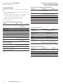
Installation and Service Manual AC Level 2 Electric Vehicle Supply Equipment (EVSE) Instruction Manual IM0EV00002E Effective December 2013 WARNING ELECTRICAL 4. Installing the Electrical Service Checking the Electrical Requirements The National Electric Code®, Article 625.21 states “Overcurrent protection for feeders and branch circuits supplying electric vehicle supply equipment shall be sized for continuous duty and shall have a rating of not less than 125 percent of the maximum load of the electric vehicle supply equipment.” A load study of the location’s electrical service may be needed to determine the availability of adequate electrical service. Take the nameplate amperage rating of the Level 2 EVSE, and multiply by 125% for the minimum upstream circuit protection needed. Check your local jurisdictions for any other electrical requirements. WARNING – LOCKOUT/TAGOUT ALL ELECTRICAL SOURCE CIRCUITS FEEDING THE UNIT(S) IN THE OPEN POSITION BEFORE BEGINNING WIRING OR TERMINATIONS. FAILURE TO FOLLOW THE INSTRUCTIONS COULD RESULT IN SEVERE BODILY INJURY OR DEATH. WARNING THIS UNIT IS RATED FOR INDOOR OR OUTDOOR INSTALLATION. IF THIS UNIT IS MOUNTED OUTDOORS, THE HARDWARE FOR CONNECTING THE CONDUITS TO THE UNIT MUST BE RATED FOR OUTDOOR INSTALLATION AND BE INSTALLED PROPERLY TO MAINTAIN THE PROPER NEMA 3R RATING ON THE UNIT. Running the Wires Once the proper electrical overcurrent device has been installed, wire needs to be run from it to the EVSE. For a typical installation, the only field wires will be for the incoming electrical service. If installing a 120vac receptacle onto the EVSE, additional service and wiring will be needed. If the EVSE unit has a remote management option, a standard CAT5/6 network cable or 3-wire shielded cable typical for a RS485 type network could also need to be run to the unit. The AC Level 2 EVSE operates on a single-phase service – two hots, and one ground. IMPORTANT CONFIRM WITH THE LOCAL ELECTRICAL REQUIREMENTS FOR THE GAUGE, TEMPERATURE RATING, AND TYPE OF WIRE MATERIAL USED FOR THE OVERCURRENT RATING FOUND BELOW. THE CHART SHOWS A GENERAL RECOMMENDATION. Table 2. Electrical Wire Chart Style Nameplate Upstream Breaker Size NNote: Use Copper Conductors ONLY. IMPORTANT −− THE 30A LEVEL 2 EVSE REQUIRES A DEDICATED 208/240VAC 40A UPSTREAM BREAKER. −− THE 48A LEVEL 2 EVSE REQUIRES A DEDICATED 208/240 VAC 60A UPSTREAM BREAKER −− THE 70A LEVEL 2 EVSE REQUIRES A DEDICATED 208/240VAC 90A UPSTREAM BREAKER. −− THE ADDITION OF A 120VAC RECEPTACLE REQUIRES DEDICATED 125% RATED UPSTREAM BREAKER. −− DO NOT USE GFCI BREAKERS. GFCI EXISTS IN EVSE AND ON EATON RECOMENDED 120VAC RECEPTACLE −− THE END USER IS RESPONSIBLE FOR ARC-FLASH HAZARD CATEGORY INFORMATION. −− FOR UNITS WITH CIRCUIT BREAKER 60A OR GREATER, END USER MUST INSTALL DISCONNECT MEANS CONSISTENT WITH NEC REQUIREMENTS - ARTICLE 625.23. −− THIS EVSE IS NOT SUITABLE FOR LOCATION AS IDENTIFIED IN NEC ARTICLE 500 (CLASSIFIED LOCATIONS). The commercial AC Level 2 product is designed to include a mounting provision for a customer supplied 120vac receptacle for field installation upon commissioning. Eaton recommends Cooper Wiring Devices by Eaton 20A receptacle with ground fault (COOPER VGF20GY) and the NEMA 3R receptacle cover (GARVIN WPCV1GWIU). For detail on termination see page 10. 4 EATON CORPORATION www.eaton.com Suggested Suggested Suggested Wire Gauge Wire Type Wire Temp Rating Wall-mount SAR_B* 30A 40A 8 AWG Copper 75 degrees C SAR_C* 48A 60A 6 AWG Copper 75 degrees C SAR_D* 70A 90A 4 AWG Copper 75 degrees C Pedestal SBR_B* 30A 40A 8 AWG Copper 75 degrees C SBR_C* 48A 60A 6 AWG Copper 75 degrees C SBR_D* 70A 90A 4 AWG Copper 75 degrees C