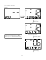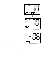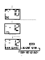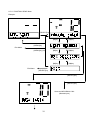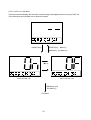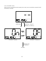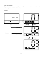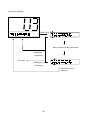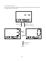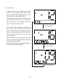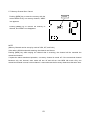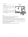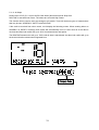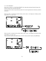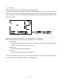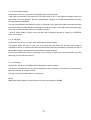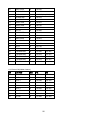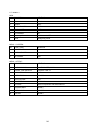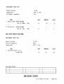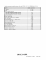
1
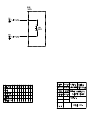
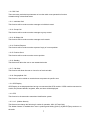
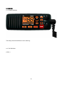
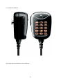
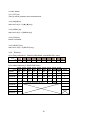
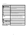
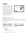
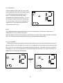
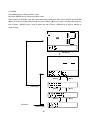
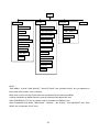
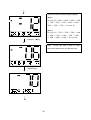
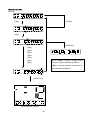
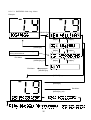
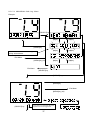
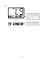
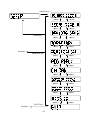
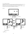
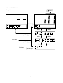
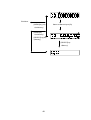
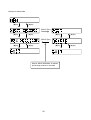
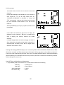
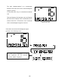
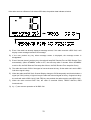
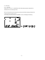
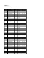
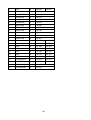
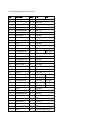
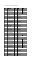
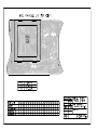
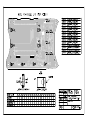
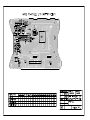
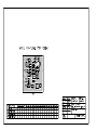
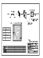
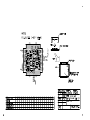
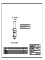
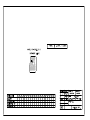
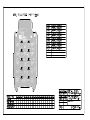
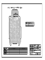
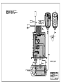
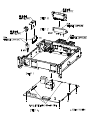
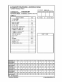
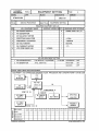
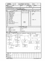
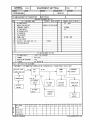
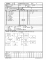
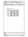
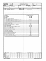
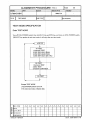
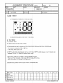
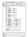
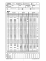
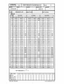
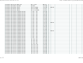
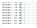
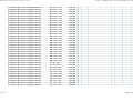
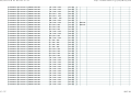
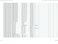
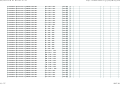
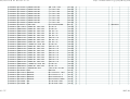
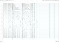
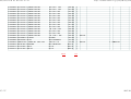
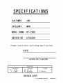
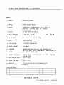
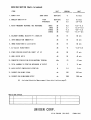
Service Manual
for
RT-2500
Japan Marina Co., Ltd.
‘
Corporation
02.09 JQD824ZF002 R0
< CONTENTS >
1. FEATURES............................................................................................................................................. 6
1.1. Contrast Adjusting............................................................................................................................ 6
1.2. Lamp Adjusting ................................................................................................................................ 6
1.3. Key Tone On/Off .............................................................................................................................. 6
1.4. Alarm Clock...................................................................................................................................... 6
1.5. Directory........................................................................................................................................... 6
1.6. Auto Channel Switch ....................................................................................................................... 6
1.7. Position Reply.................................................................................................................................. 6
1.8. Channel Tag..................................................................................................................................... 6
1.9. MMSI................................................................................................................................................ 6
1.10. High/Low Function ......................................................................................................................... 6
1.11. STEP .............................................................................................................................................. 6
1.12. DSC Call ........................................................................................................................................ 7
1.12.1. Individual Call.......................................................................................................................... 7
1.12.2. Group Call ............................................................................................................................... 7
1.12.3. All Ships Call ........................................................................................................................... 7
1.12.4. Position Request..................................................................................................................... 7
1.12.5. Position Send .......................................................................................................................... 7
1.12.6. Standby ................................................................................................................................... 7
1.12.7. Call Wait.................................................................................................................................. 7
1.12.8. Geographical Call ................................................................................................................... 7
1.13. GPS Display .................................................................................................................................. 7
1.14. ATIS ............................................................................................................................................... 7
1.15. U.I.C. (Hidden feature) .................................................................................................................. 7
2. DESIGN.................................................................................................................................................. 8
2.1. FRONT DESIGN.............................................................................................................................. 8
2.2. TOP DESIGN................................................................................................................................... 8
2.3. HAND MIC DESIGN ........................................................................................................................ 9
3. CONTROLS AND FUNCTIONS........................................................................................................... 10
3.1. FRONT Switch............................................................................................................................... 10
3.1.1. [POWER/VOLUME] knob ....................................................................................................... 10
3.1.2. [SQUELCH] knob .................................................................................................................... 10
3.1.3. [ ], [ ] key ............................................................................................................................ 10
3.1.4. [SELECT] key.......................................................................................................................... 10
3.1.5. [MENU] key ............................................................................................................................. 10
3.1.6. [HI/LO] key .............................................................................................................................. 10
3.1.7. [16/9 /TRI] key......................................................................................................................... 10
3.1.8. [STEP/SCAN] key ................................................................................................................... 10
3.1.9. [MEM] key ................................................................................................................................11
2
3.1.10. [PA] key ..................................................................................................................................11
3.1.11. [DISTRESS] key.....................................................................................................................11
3.2. MIC Switch..................................................................................................................................... 12
3.2.1. [PTT] key................................................................................................................................. 12
3.2.2. [ ] [ ] key ............................................................................................................................. 12
3.2.3. [MENU] key ............................................................................................................................. 12
3.2.4. [CLR] key ................................................................................................................................ 12
3.2.5. [SELECT] key.......................................................................................................................... 12
3.2.6. TEN keys................................................................................................................................. 12
4. LCD DISPLAY ...................................................................................................................................... 13
4.1. ICON
Detail ................................................................................................................................. 14
4.2. 14seg. Character Pattern .............................................................................................................. 15
5. OPERATIONS ...................................................................................................................................... 16
5.1. POWER ON/OFF........................................................................................................................... 16
5.2. Channel Select .............................................................................................................................. 16
5.3. Transmission.................................................................................................................................. 17
5.4. HI/LO POWER............................................................................................................................... 17
5.5. MENU ............................................................................................................................................ 18
5.5.1. DSC CALL Menu..................................................................................................................... 20
5.5.1.1. INDIVIDUAL CALL Menu ................................................................................................. 21
5.5.1.2. GROUP CALL Menu ........................................................................................................ 25
5.5.1.3. ALL SHIPS CALL Menu.................................................................................................... 27
5.5.1.4. POSITION REQUEST CALL Menu.................................................................................. 29
5.5.1.5. POSITION SEND Menu ................................................................................................... 31
5.5.1.6. STANDBY Menu............................................................................................................... 33
5.5.1.7. CALL WAIT Menu ............................................................................................................. 34
5.5.2. SETUP Menu .......................................................................................................................... 40
5.5.2.1. ALARM CLOCK Menu...................................................................................................... 42
5.5.2.2. LOCAL TIME ADJUST Menu ........................................................................................... 44
5.5.2.3. DAYLITE SAVE Menu ...................................................................................................... 45
5.5.2.4. DIRECTORY Menu .......................................................................................................... 46
5.5.2.5. AUTO CH SW Menu......................................................................................................... 51
5.5.2.6. POS REPLY Menu ........................................................................................................... 52
5.5.2.7. CH TAG Menu .................................................................................................................. 53
5.5.2.8. GROUP MMSI Menu........................................................................................................ 55
5.5.2.9. USER MMSI Menu ........................................................................................................... 56
5.5.2.10. ATIS ID Menu ................................................................................................................. 57
5.5.3. SYSTEM Menu ....................................................................................................................... 58
5.5.3.1. CONTRAST Menu............................................................................................................ 59
5.5.3.2. LAMP ADJUST Menu ....................................................................................................... 60
3
5.5.3.3. KEY BEEP Menu.............................................................................................................. 61
5.6. 16CH / 9CH ................................................................................................................................... 62
5.7. Memory Channel Set / Cancel ...................................................................................................... 63
5.8. Triple Watch ................................................................................................................................... 64
5.9. Scan mode..................................................................................................................................... 65
5.9.1. Triple watch scan .................................................................................................................... 66
5.9.2. Normal scan ............................................................................................................................ 66
5.10. Distress ........................................................................................................................................ 67
5.11. DSC Call ...................................................................................................................................... 71
5.11.1. Individual ............................................................................................................................... 71
5.11.2. Group..................................................................................................................................... 73
5.11.3. All Ships................................................................................................................................. 74
5.11.4. POS. REQUEST ................................................................................................................... 75
5.11.5. POS. SEND........................................................................................................................... 77
5.11.6. Geographical Call.................................................................................................................. 77
5.11.7. Standby.................................................................................................................................. 78
5.11.8. Auto Channel Switch ............................................................................................................. 79
5.11.9. Call Wait ................................................................................................................................ 79
5.11.10. Directory .............................................................................................................................. 79
5.12. Step.............................................................................................................................................. 80
5.13. U.I.C............................................................................................................................................. 80
5.14. Other Function ............................................................................................................................. 81
5.14.1. GPS Display.......................................................................................................................... 81
5.14.2. PA.......................................................................................................................................... 84
5.14.3. Hi/Lo Battery detect .............................................................................................................. 84
5.14.4. GPS ANTENNA DETECT ICON ........................................................................................... 85
5.14.5. Last Channel Memory........................................................................................................... 85
5.14.6. Inlandwater way Mode/Seagoing Mode ............................................................................... 85
5.14.7. Free CH active ON/OFF(Hidden feature) ............................................................................. 86
6. Reference ............................................................................................................................................. 87
6.1. International Frequencies and Channels ...................................................................................... 87
6.2. USA Frequencies and Channels ................................................................................................... 89
6.3. Canada Frequencies and Channels.............................................................................................. 91
6.4. Extend CH(Hidden feature) ........................................................................................................... 92
6.5. Only Low power CH....................................................................................................................... 93
6.6. Tones ............................................................................................................................................. 93
6.7. Initialize .......................................................................................................................................... 94
4
Revision History
5
1. FEATURES
1.1. Contrast Adjusting
This feature will allow the user to change the contrast levels of the LCD.
1.2. Lamp Adjusting
This feature will allow the user to adjust the brightness level of the back lighting of the LCD screen.
1.3. Key Tone On/Off
Key Tone can be selected On/Off.
1.4. Alarm Clock
This feature can sound alarm at the time, which the user set up. However, this function cannot be used
unless the GPS module is connected.
1.5. Directory
This function will allow the user to send Individual Call etc. Directory is the function to memorize the
name and number of 20 other vessels.
1.6. Auto Channel Switch
This feature is to allow the user to disable the automatic channel change when receiving a DSC Call.
1.7. Position Reply
This item in the Setup Menu will allow the user turn on or off the automatic Position Reply that a vessel
asks for the user position.
1.8. Channel Tag
This item in the Setup Menu will allow the user to change the normal channel tags (names).
1.9. MMSI
MMSI is the identification number of vessel. In case of state of emergency, an identification number is
sent from a communication machine and rescue is requested from other vessels etc.
1.10. High/Low Function
This feature will allow the user to change output to set less than 25W or less than 1W.
1.11. STEP
This feature will allow the radio will step to the next channel that has been memorized for scan channel.
6
1.12. DSC Call
There are many technical requirements on how the radio must operate this function.
A detailed thing is described below.
1.12.1. Individual Call
This function will be used to send a message to individual vessel.
1.12.2. Group Call
This function will be used to send a message to group vessel.
1.12.3. All Ships Call
This function will be used to send a message to all vessels.
1.12.4. Position Request
This function will be used to send a request of reply of current position.
1.12.5. Position Send
This function will be used to send a current position.
1.12.6. Standby
This feature will allow the user to set unattended mode.
1.12.7. Call Wait
This function will allow the user to view a list of received calls.
1.12.8. Geographical Call
This function can be called to vessels these are present in specific area.
1.13. GPS Display
GPS Display is not displayed when having not connected the GPS module. If GPS module connected to
a radio, the present latitude, longitude, date, and time will be displayed.
1.14. ATIS
This function is the automatic transmitter identification system.
1.15. U.I.C. (Hidden feature)
This feature can change the following 3 modes of operation; USA, INT and CAN.
This hidden feature is enabled when user is pushing and holding [HI/LO] & [SELECT]keys and turn on
the radio.
7
2. DESIGN
2.1. FRONT DESIGN
This design has some difference from real thing.
2.2. TOP DESIGN
( None )
8
2.3. HAND MIC DESIGN
This design has some difference from real thing.
9
3. CONTROLS AND FUNCTIONS
3.1. FRONT Switch
3.1.1. [POWER/VOLUME] knob
Turns this radio on and off as well as adjusts the audio volume.
3.1.2. [SQUELCH] knob
Sets the point at which random noise on the channel does not activate the audio circuits but a received
signal does.
3.1.3. [ ], [ ] key
[ ] is able to move up the channels. [ ] is able to move down the channels.
[ ] is able to move up an item of Menu. [ ] is able to move down an item of Menu.
3.1.4. [SELECT] key
An item is decided by pushing this key in Menu mode.
3.1.5. [MENU] key
Push this key to appear Menu Command. These options will control the following categories; DSC CALL,
SETUP, and SYSTEM within each of these categories, there will be Submenu options that are outlined in
the attached document.
3.1.6. [HI/LO] key
Push this key to change output power.
3.1.7. [16/9 /TRI] key
Pushing this key immediately recalls EMG 16CH from any location except 16CH. Next push this key to
recall EMG 9CH. Pushing this key again reverts the radio to the previous select channel. Pushing and
holding this key for 2 seconds will activate the triple watch feature.
3.1.8. [STEP/SCAN] key
Push this key to activate the step operation. Every time this key is pushed, the radio will step to the next
channel that has been placed into Memory.
Pushing and holding this key for 2 seconds will activate the channel scan feature.
10
3.1.9. [MEM] key
Push this key to add the current channel to scanning memory. Pushing this key again, it will delete the
channel from scanning memory. This key will press and hold, it is possible to select USA / International /
Canadian mode. (Hidden feature)
3.1.10. [PA] key
Push this key to enable the PA(Public Address) feature. This key will press and hold, it is possible to
select Inlandwater way / Seagoing mode.
3.1.11. [DISTRESS] key
Push this key to call an emergency. If it does so, a rescue signal will send towards a surrounding vessel.
11
3.2. MIC Switch
3.2.1. [PTT] key
This key will be pushed to send a transmission.
3.2.2. [ ] [ ] key
Same as P.10 [3.1.3 [ ], [ ] key].
3.2.3. [MENU] key
Same as P.10 [3.1.5 [MENU] key].
3.2.4. [CLR] key
Delete a character.
3.2.5. [SELECT] key
Same as P.10 [3.1.4 [SELECT] key].
3.2.6. TEN keys
a) For Entry Channel No., GROUP/USER MMSI, and DIRECTORY menu
1 press
1
2
3
4
5
6
7
8
9
0
b) For Name data entry in DIRECTORY Menu
1 press
@
A
D
G
J
M
P
T
W
_
2 presses
-
B
E
H
K
N
Q
U
X
<Blank>
3 presses
=
C
F
I
L
O
R
V
Y
(
4 presses
/
2
3
4
5
6
S
8
Z
)
5 presses
<
9
’
6 presses
>
7 presses
+
7
0
8 presses
9 presses
1
12
4. LCD DISPLAY
This area is used for Channel Tag, Menu, and message of DSC, GPS.
These messages will continually scroll from right to the left.
13
4.1. ICON Detail
ICON
DETAIL
(“ TX” Icon)
This icon is turned on during transmitting.
This icon will be displayed when the radio is in the DSC mode,
including receiving DSC Call.
This icon is turned on when the transmit power is a less than 1W
output.
This icon is turned on when the transmit power is a less than 25W
output.
This icon is the mode that can receive EMG 16CH, EMG 9CH and
current channel are scanning by turns.
This icon is turned on (Blink) when Inlandwater way mode active.
U icon is turned on when the channel is in USA mode.
I icon is turned on when the channel is in International mode.
C icon is turned on when the channel is in Canada mode.
Note : These icons indicate in U.I.C. (Hidden feature) function.
This icon is turned on when the current channel is a memory
channel.
This icon is turned on when the ALARM function is turned on.
This icon (no waves) is turned on when GPS data is invalid.
These icons are turned on when GPS data is effective.
14
4.2. 14seg. Character Pattern
CHR
FONT
FONT
G
CHR
FONT
FONT
FONT
FONT
CHR
CHR
CHR
CHR
CHR
FONT
CHR
FONT
FONT
CHR
4
FONT
CHR
FONT
CHR
CHR
FONT
CHR
FONT
FONT
CHR
FONT
<
FONT
CHR
CHR
FONT
FONT
CHR
CHR
CHR
FONT
CHR
FONT
FONT
CHR
FONT
FONT
CHR
FONT
FONT
15
CHR
CHR
CHR
CHR
FONT
CHR
FONT
CHR
CHR
FONT
CHR
FONT
T
FONT
CHR
FONT
1
FONT
CHR
FONT
8
FONT
*
FONT
FONT
M
7
>
CHR
FONT
Z
)
CHR
CHR
CHR
F
S
6
CHR
FONT
L
Y
=
FONT
CHR
CHR
E
R
5
FONT
FONT
K
(
/
FONT
CHR
X
FONT
CHR
D
Q
W
FONT
FONT
J
P
FONT
CHR
C
0
CHR
FONT
3
9
CHR
CHR
FONT
I
V
2
CHR
FONT
O
U
CHR
CHR
CHR
B
H
N
CHR
FONT
A
Blank
CHR
CHR
CHR
FONT
+
FONT
CHR
FONT
FONT
CHR
FONT
@
FONT
CHR
5. OPERATIONS
5.1. POWER ON/OFF
This knob will be rotated in a clockwise
direction in order to turn the radio on. Upon
turning the radio on there will be a click feel
and a Wake Up Tone with message of
“RT-2500
>
MMSI
:
XXXXXXXXX”.
(XXXXXXXXX = User MMSI Data or “NO
DATA”) As the knob is rotated clockwise,
each volume level will have a click feel up to
the maximum volume level. Upon turning on
the radio, the channel displayed will be the
last channel selected before the radio was
turned off. The first time the radio is turned
on, channel 16 will be selected.
5.2. Channel Select
[ ] key is used to scroll up through the channels.
[ ] key is used to scroll down through the channels.
If either [ ] or [ ] keys are held down for an interval of 0.5 seconds, the channel display will quickly
scroll in the direction of the appropriately held key. The radio will sounds Key Tone (Single) only when
[ ] or [ ] keys was pushed.
<< [ ] key >>
<< [ ] key >>
User can select channel number by [TEN] Key and [SELECT] Key.
Example.
1 : Push [1] key.
2 : Push [2] key.
3 : Push [SELECT] key.
=> The channel number will change to “12”
Channel 70 is used DSC only, user cannot select channel 70.
16
5.3. Transmission
Push and hold [PTT] key, the “TX” icon on the
LCD is displayed. While the user pushes [HI/LO]
key while the radio has transmitted by low
power, it is possible to output high power.
Transmit time is limited to 5 minutes. “TX” icon
and channel number blinks when transmit time
is over 5 minutes. This prevents unintentional
transmissions. (The radio cannot transmit on
15CH(USA) by [PTT] key.)
NOTE
The ATIS signal shall be transmitted at the end of each transmission. The end of a transmission is
considered to be every release of [PTT] key.
When the radio is turned on while [PTT] key is held down, PTT Error Tone sounds, the channel indicator
and “TX” icon blinks. All key except [HI/LO] key is not accepted during transmitting.
5.4. HI/LO POWER
Pushing [HI/LO] key will change the transmit output power for the currently selected channel from HI
(less than 25W) to LO (less than 1W) or from LO to HI depending on the current setting. Push [HI/LO]
key, turn on “LO” icon; the transceiver can transmit with less than 1W. Once again, if this key is pushed, it
will change to HI icon, the transceiver can transmit with less than 25W. The radio can’t switch TX
Power when it is scanning of SCAN mode.
[HI/LO]
key
17
5.5. MENU
Push [MENU] key to change to Menu mode.
Next push [MENU] key to cancel from Menu mode.
These options in the Menu mode will control the following categories: DSC CALL, SETUP, and SYSTEM.
[ ] key is used for scrolling down through the item of Menu. [ ] key is used for scrolling up through the
item of Menu. [SELECT] key is used to select the item of Menu. [MENU] key is used to change up
class of Menu.
[MENU]key
[ ]key
[ ]key
[ ]key
[ ]key
[ ]key
[ ]key
[MENU]key
Exit Menu
[SELECT]key
18
NOTE
“POS SEND”, “LOCAL TIME ADJUST”, “DAYLITE SAVE” and “ALARM CLOCK” are not displayed in
Menu when GPS module is not connected.
EMG mode, Scan mode and Triple watch are canceled when the radio enter MENU.
It will be canceled from MENU when the radio is transmitted and takes DSC Call.
When [DISTRESS], [PTT] key is pushed, it will be canceled from MENU mode.
When Inlandwater way Mode, “INDIVIDUAL”, “GROUP”, “ALL SHIPS”, “POS REQUEST” and “POS
SEND” are not selected. (Error Tone)
19
5.5.1. DSC CALL Menu
[SELECT]key
[ ]key
[ ]key
[ ]key
[ ]key
[ ]key
[ ]key
[ ]key
[ ]key
[ ]key
[ ]key
[ ]key
[ ]key
[ ]key
[ ]key
[MENU]key
Exit Menu
[MENU]key (2S)
Exit Menu
[SELECT]key
20
5.5.1.1. INDIVIDUAL CALL Menu
Example:
[SELECT]key
[ ]key
[ ]key
[MENU]key
[ ]key
[ ]key
[MENU]key (2S)
[ ]key
[ ]key
Exit Menu
Exit Menu
[SELECT]key
[SELECT]key
[SELECT]key
To Manual Input
(Select Inter-ship channel)
21
Select Inter-ship Channel by [ ] or [ ]key.
[ ]key :
[ ]key:
Example : [ ]key
Note : Group Call also is able to select
inter-ship channel same as Individual Call.
[SELECT]key
22
TX Power : High
Individual Call is sent with High Power.
Return to idle screen.
Receive the ACK.
23
Manual Input (ID)
Example:
[1]key
[CLR]key
[2]key
[MENU]key
[3]key
[4]key
[5]key
[6]key
[7]key
[8]key
NOTE: [
[9]key
position to right in Manual Input(Menu).
]key is used to change cursor
[ ]key is used to change cursor position to
left in Manual Input(Menu).
[SELECT]key
Select Inter-ship channel
24
5.5.1.2. GROUP CALL Menu
Example:
[SELECT]key
[SELECT]key
Select Inter-ship channel
Select Inter-ship Channel by [ ] or [ ]key.
Example : [ ]key
Same as [5.5.1.1. INDIVIDUAL CALL Menu].
[SELECT]key
25
TX Power : Low
Return to idle screen.
Group Call is sent with Low Power.
26
5.5.1.3. ALL SHIPS CALL Menu
Example:
[SELECT]key
[ ]key
[ ]key
[ ]key
[ ]key
[MENU]key
Exit Menu
[MENU]key (2S)
Exit Menu
[SELECT]key
[SELECT]key
27
Routine : TX Power Low
Other : TX Power High
Return to idle screen.
28
5.5.1.4. POSITION REQUEST CALL Menu
Example:
[SELECT]key
[ ]key
[ ]key
[ ]key
[ ]key
[ ]key
[ ]key
[MENU]key
Exit Menu
[MENU]key (2S)
Exit Menu
[SELECT]key
[SELECT]key
[SELECT]key
Same as INDIVIDUAL CALL
(Manual Input)
29
TX Power : High (Position Request Call is sent with High Power.)
Return to idle screen
Receive the Reply.
UTC Time
30
5.5.1.5. POSITION SEND Menu
Example:
[SELECT]key
[ ]key
[ ]key
[ ]key
[ ]key
[ ]key
[ ]key
[MENU]key
Exit Menu
[MENU]key (2S)
Exit Menu
[SELECT]key
[SELECT]key
[SELECT]key
Same as INDIVIDUAL CALL
(Manual Input)
31
TX Power : High
Position Send Call is sent with High Power.
32
5.5.1.6. STANDBY Menu
Example:
[SELECT]key
33
5.5.1.7. CALL WAIT Menu
Log
Example:
[SELECT]key
[ ]key
[ ]key
[ ]key
[ ]key
[MENU]key
Exit Menu
[MENU]key (2S)
Exit Menu
[SELECT]key
[SELECT]key
[SELECT]key
INDIVIDUAL CALL Log..
34
DISTRESS CALL Log.
5.5.1.7.1. DISTRESS CALL Log. Menu
Example:
[SELECT]key
[ ]key
[ ]key
[ ]key
[ ]key
[ ]key
[ ]key
[MENU]key
Ex.) If user has not checked the log,
the log will be blinked.
Exit Menu
[MENU]key (2S)
Exit Menu
[SELECT]key
[SELECT]key
[MENU]key
Exit Menu
[MENU]key (2S)
35
If the radio is not connected GPS, the log data have not the logged time.
36
5.5.1.7.2. INDIVIDUAL CALL Log. Menu
Example:
[SELECT]key
[ ]key
[ ]key
[ ]key
[ ]key
[ ]key
[ ]key
[MENU]key
Ex.) If user has not checked the log,
the log will be blinked.
Exit Menu
[MENU]key (2S)
Exit Menu
[SELECT]key
[SELECT]key
[MENU]key
Exit Menu
[MENU]key (2S)
[SELECT]key
If the radio is not connected GPS, the
log data have not the logged time.
37
Select Inter-ship Channel by [ ] or [ ]key.
Example : [ ]key
Same as [5.5.1.1. INDIVIDUAL CALL Menu].
[SELECT]key
TX Power : High
Same as INDIVIDUAL CALL Menu
38
NOTE
If ID of “KENT NEWMAN” is
memorized in directory already,
“KENT
NEWMAN”
will
be
indicated.
If this ID is not memorized in
directory, this ID will be indicated.
39
5.5.2. SETUP Menu
This section has explained about Setup of this radio.
Items in Setup Menu are as follows.
ALARM CLOCK
LOCAL TIME ADJUST
DAYLITE SAVE
DIRECTORY
AUTO. CH.SW
POS. REPLY
CH TAG
GROUP MMSI
USER MMSI
ATIS ID
40
[SELECT]key
[ ]key
[ ]key
[ ]key
[ ]key
[ ]key
[ ]key
[MENU]key
[ ]key
[ ]key
[ ]key
[ ]key
[ ]key
[ ]key
[ ]key
[ ]key
[ ]key
[ ]key
[ ]key
[ ]key
[ ]key
[ ]key
Exit Menu
[MENU]key (2S)
Exit Menu
41
5.5.2.1. ALARM CLOCK Menu
This feature will allow the user to set the alarm based on satellite time only if GPS is connected to the
NMEA0183 jack. This option will only appear in the options list if a GPS is added to the unit.
When set-up time comes, the radio will generate alarm. While alarm is generated, “ALARM” icon blinks.
Push any key, in order to cancel alarm and disappear the “ALARM” icon.
Example:
[SELECT]key
[MENU]key not Memory
( ALARM On/Off Select Screen )
[ ]key
[ ]key
[SELECT]key
[MENU]key (2S)
ALARM On
Exit Menu
not Memory
Exit Menu
[SELECT]key (2S)
42
[SELECT]key
ALARM Off
Exit Menu
( ALARM Time Set )
ALARM On/Off Select Screen
[CLR]key
[1]key
[MENU]key
not Memory
[0]key
Exit Menu
[MENU]key (2S)
not Memory
[SELECT]key (2S)
[2]key
[4]key
[2](A)key
[SELECT]key
NOTE: [ ]key is used to change cursor position to right.
[ ]key is used to change cursor position to left.
43
5.5.2.2. LOCAL TIME ADJUST Menu
This feature allows to adjusting local time –1H to + 1H.
The following screens illustrate how to select this feature.
[SELECT]key
[SELECT]key
Memory
[MENU]key not Memory
[ ]key
[ ]key
Local Time +1H
Local Time +0H
[ ]key
Exit Menu
[MENU]key (2S)
not Memory
Local Time – 1H
44
[ ]key
5.5.2.3. DAYLITE SAVE Menu
This feature allows changing the summer time is turned on or off.
The following screens illustrate how to select this feature.
[SELECT]key
[SELECT]key
Memory
[MENU]key not Memory
[ ]key
[ ]key
Summer Time : On
Summer Time : Off
[MENU]key (2S)
not Memory
Exit Menu
45
5.5.2.4. DIRECTORY Menu
Example 1:
directory
[SELECT]key
[ ]key
[ ]key
[ ]key
[ ]key
[ ]key
[ ]key
[MENU]key
Exit Menu
[MENU]key (2S)
Exit Menu
[SELECT]key
46
Example 2: Set New Data
[SELECT]key
[2]key
[2]key
[CLR]key
[MENU]key
not Memory
[2]key x 2
Exit Menu
[MENU]key (2S)
not Memory
[SELECT]key
[3]key
[SELECT]key
[SELECT]key(2S)
( [SELECT]key x 9 )
[SELECT]key
NOTE: [ ]key is used to change cursor position to right.
[ ]key is used to change cursor position to left.
47
Exit Menu
[MENU]key (2S)
Same as Manual Input (ID)
not Memory
[MENU]key
not Memory
[SELECT]key(2S)
(Memory)
[SELECT]key
Memory
48
Example 3: Edit Data
[SELECT]key
[ ]key
[ ]key
[ ]key
[ ]key
[MENU]key
Exit Menu
[MENU]key (2S)
Exit Menu
[SELECT]key
[SELECT]key
Name Edit
ID Edit
( same as “Set New Data” )
49
Example 4: Delete Data
[ ]key
[ ]key
[SELECT]key
[ ]key
[ ]key
[ ]key
[ ]key
[ ]key
[ ]key
[SELECT]key
[ ]key
[ ]key
Data of “KENT NEWMAN” is deleted,
and change position to next data.
50
5.5.2.5. AUTO CH SW Menu
This feature allows disabling the automatic channel change that happens when receiving a DSC Call.
The following screens illustrate how to select this feature.
[SELECT]key
[SELECT]key
Memory
[MENU]key not Memory
[ ]key
[ ]key
AUTO CH SW : On
AUTO CH SW : Off
[MENU]key (2S)
not Memory
Exit Menu
51
5.5.2.6. POS REPLY Menu
When this radio is requested the position data by other vessel, the user can decide to transmit the ACK
automatically or manually.
[SELECT]key
[SELECT]key
Memory
[MENU]key not Memory
[ ]key
[ ]key
POS REPLY : On(Auto)
POS REPLY : Off (Manual)
[MENU]key (2S)
not Memory
Exit Menu
52
5.5.2.7. CH TAG Menu
This feature allows setting name each MRN channel. (The user can name for the channel of each of
U.I.C mode.) Max character of the TAG is 12digits.
Example 1:
[SELECT]key
[ ]key
[ ]key
[ ]key
[ ]key
[MENU]key
Exit Menu
[MENU]key (2S)
53
Example 2: Edit Data
[SELECT]key
Same as Edit of DIRECTORY Name
[MENU]key
not Memory
Exit Menu
[MENU]key (2S)
not Memory
[SELECT]key (2S)
(Memory)
54
5.5.2.8. GROUP MMSI Menu
Group MMSI is composed by number of 9 digits.
This MMSI is used to Group Call.
group MMSI
[SELECT]key
Same as Manual Input (ID)
[MENU]key
not Memory
Exit Menu
[MENU]key (2S)
not Memory
[SELECT]key (2S)
(Memory)
[SELECT]key
(Memory)
Note : The first digit of a Group MMSI is preselected “0” in the radio.
55
5.5.2.9. USER MMSI Menu
USER MMSI is composed by number of 9 digits. The specifications for this feature state that the radio
can only be programmed 1 time. If the radio needs changing the MMSI 2times, the user should send
back to Uniden for reprogramming.
User MMSI
[SELECT]key
[CLR]key
Same as Manual Input (ID)
[MENU]key
not Memory
Exit Menu
[MENU]key (2S)
not Memory
[SELECT]key (2S)
(Memory)
[SELECT]key
(Memory)
56
5.5.2.10. ATIS ID Menu
The ATIS ID is composed by number of 10 digits. The first digit of ATIS ID is preselected “9” in the radio.
The ATIS ID can only be entered once. If it is necessary to change the ATIS ID, the user should send
back to Uniden for reprogramming.
programming
1. The unit power supply is turned on pushing [HI/LO]key and [MENU]key.
ATIS ID
Usually, only a check is.
[SELECT]key
[MENU]key
Same as Manual Input (ID)
not Memory
Exit Menu
[MENU]key (2S)
not Memory
[SELECT]key (2S)
(Memory)
[SELECT]key
(Memory)
57
5.5.3. SYSTEM Menu
This section has explained about setting of System of this radio.
Items in System Menu are as follows.
CONTRAST
LAMP ADJUST
KEY BEEP
[SELECT]key
[ ]key
[ ]key
[ ]key
[ ]key
[ ]key
[ ]key
[MENU]key
Exit Menu
[MENU]key (2S)
Exit Menu
[SELECT]key
58
5.5.3.1. CONTRAST Menu
This option allows changing the contrast levels of the LCD.
The contrast can be set as 0 - 7 levels continuously.
The each level has adjusting of 5step.
[SELECT]key
[SELECT]key
Memory
[MENU]key not Memory
[ ]key (*1)
[ ]key(*1)
[MENU]key (2S)
not Memory
Exit Menu
*1 : Push and hold the key.
59
5.5.3.2. LAMP ADJUST Menu
The feature allows changing the brightness level of the back lighting of the LCD screen and the keys.
The brightness can be set as 4 levels.
[SELECT]key
[SELECT]key
Memory
[MENU]key not Memory
[ ]key
[ ]key
[MENU]key (2S)
not Memory
Exit Menu
60
5.5.3.3. KEY BEEP Menu
This feature allows changing the Key Beep (Key Tone, Error Tone and Wake Up Tone) is enabled (on) or
disabled (off).
[SELECT]key
[SELECT]key
Memory
[MENU]key not Memory
[ ]key
[ ]key
[MENU]key (2S)
not Memory
Exit Menu
61
5.6. 16CH / 9CH
Pushing [16/9 /TRI] key immediately recalls EMG
16CH from any location except when current
channel is 16CH. ( But if Triple watch mode is ON,
the channel will change to EMG 16CH. )
And the transmit output power will change to HI in
16CH. Next push [16/9 /TRI] key to recall EMG
9CH. Pushing [16/9 /TRI] key again reverts the
radio to the previous select channel.
Push [16/9] key
When [16/9 /TRI] key is pushed on conditions that
Scan mode or Triple watch mode is ON, Scan
mode or Triple watch mode is stopped temporarily.
When [PTT] key is pushed on condition that EMG
mode is ON, Triple watch mode or Scan mode
has be canceled.
When [16/9 /TRI] key is pushed when Triple watch
mode or Scan mode has stopped temporarily, then
these modes will be recalled.
When [16/9 /TRI], [ ], [ ], and [STEP/SCAN] key
is pushed, EMG mode is canceled.
Push [16/9] key
Push [16/9] key
62
5.7. Memory Channel Set / Cancel
Pushing [MEM] key to store the memory with the
On/Off
current MRN CH by not memory channel, “MEM”
icon appears.
Pushing [MEM] key to remove the memory of
channel, and “MEM” icon disappears.
NOTE
(Memory Channel can be set up by mode of USA, INT, and CAN.)
If the radio is SCAN mode with scanning, the channel can’t be set.
Pushing [MEM] key while staying the channel that is scanning, the channel will be canceled the
memorized channel.
If repeat the above-mentioned operation, a memory channel is turned off. If the memorized channel
becomes only one channel, scan mode will turn off and will turn into MRN Idle mode. Only one
memorized channel is set as current channel. It cannot be cancel all memory channels at the same time.
63
5.8. Triple Watch
On/Off
This function carries out scan of 9CH, 16CH, and
current channel.
Pushing and holding [16/9 /TRI] key for 2 seconds
in state of Triple watch off, it is set to Triple watch
on,
“TRI”
icon
and
message
of
“TRIPLE
WATCHING” appears.
Pushing and holding [16/9 /TRI] key for 2 seconds
in state of Triple watch on, it is set to Triple watch
off, and “TRI” icon and message of “TRIPLE
WATCHING” disappears.
NOTE
Triple watch receives EMG 16CH, EMG 9CH, and Current CH by turns.
If 9CH is busy, Triple watch receives EMG 9CH and EMG 16CH by turns.
If 16CH is busy, Triple watch only receives EMG 16CH.
If Triple watch is in EMG mode, Triple watch receives EMG 16CH, EMG 9CH and last MRN CH(16 or 9).
If user pushes [16/9 /TRI] key in Triple watch, Triple watch will be interrupted temporarily and it will be set
to EMG 16CH. If user pushes [16/9 /TRI] key once again, it will be set to EMG 9CH, and Triple watch will
be resumed if user pushes [16/9 /TRI] key once again.
Triple Watch will be resumed if a signal of EMG CH is lost for 3 seconds (Drop Out Delay Timer) in the
EMG CH Stay state of Triple Watch On.
When [DISTRESS] key and [PTT] is pushed, Triple Watch mode is canceled.
64
5.9. Scan mode
This feature will allow the user to scan the memorized
channels.
Pushing and holding [STEP/SCAN] key for 2 seconds in
scan mode off, it is set to Triple watch scan on,
“CHANNEL SCANNING” is indicated on 14seg. And
“TRI” icon appears. Pushing and holding [STEP/SCAN]
key for 2 seconds in scan mode on, it is set to scan
mode off.
When [DISTRESS] or [PTT] key is pushed, SCAN mode
is canceled.
If the radio has detected a signal, the CH digits are
displayed a stay channel. If [ ] key is pushed while
scan is staying, the memory channel can restart
scanning.
If a signal stopped when the radio is staying a channel in
Scan mode, then the radio wait to detect a signal for 3
seconds (Drop out Delay Timer). But if a signal wasn’t
detected, then restart to scan.
Pushing and holding [STEP/SCAN] key for 2 seconds by EMG 16CH or EMG 9CH, EMG 16CH or EMG
9CH will be canceled and Triple watch scan will be started. When one does not have Memory channel, it
is not set to scan mode and ring the Error Tone even if it pushed [STEP/SCAN] key. Pushing and holding
[STEP/SCAN] key for 2 seconds at the time only a memory channel, it will be set to the Memory channel,
without being set to scan mode.
Push [PTT] key or [SCAN] key in SCAN mode
(Triple Watch) Scan mode will be OFF. Current channel become as following
Scanning
Scanning CH
Scan Stay
Stay Channel
16CH Watch Stay
16CH
9CH Watch Stay
9CH
65
5.9.1. Triple watch scan
Pushing and holding [STEP/SCAN] key for 2 seconds in scan mode off, it is set to Triple watch scan on,
“CHANNEL SCANNING” is indicated on 14seg. and “TRI” icon appears.
Although current channel is scanned, EMG 16CH and EMG 9CH are watched every 2 seconds. "TRI"
turn on. Triple watch scan is not performed when the memory is not registered.
5.9.2. Normal scan
To Normal scan is turned on, pushing and holding [16/9/TRI] key for 2 seconds in Triple watch scan
mode. Although Memory channel is scanned, EMG 16CH and EMG 9CH are not watched in Normal
scan. Normal scan is not performed when the memory is not registered.
66
5.10. Distress
This feature will allow the user to transmit a Distress
Call. In order to transmit a Distress Call, push
[DISTRESS] key for 5 seconds. And select nature
code. Then push [SELECT] key. Distress Call is
sent with High Power (less than 25W).
Count down
4S –1S count down
If channel 70 is free, it transmits a Distress Call
automatically
TX Power : High
67
The radio “shadow-watches” for a transmission
between CH16 and CH70 until an acknowledgment
signal is received.
If user push [16/9 /TRI], it is canceled the Distress
Call.
Then the Distress Call has been sent, the Distress
alert will sound. Distress Call is transmitted and it
waits for about 210 - 270 seconds. This is continued
Distress Ack Wait
until an acknowledgment signal is received.
.
If this radio received an acknowledgment signal,
as shown in the following screen.
The name will be displayed if it is the
name
registered
into
the
directory.
Otherwise, MMSI is displayed.
68
If this radio takes a Distress Call, it will be displayed such as the following screen and an emergency
alarm sounds. The screen will display a message with calling radio’s MMSI(or Name), nature code, time
(hour/minute) and position (degree/minute; second data = “000”).
If the data of caller radio is attached second data of position, this radio will display second data too.
(This radio support the second data of position for Distress/Position Request Call)
Nature Code
FIRE
FLOODING
COLLISION
GROUNDING
CAPSIZING
SINKING
ADRIFT
ABANDONING
PIRACY/ARMED
OVERBOARD
UNDESIGNATED
69
If the radio receives a Distress Call without GPS data, the position data indicate as below.
A) Even if the radio has already displayed message screen, if the radio received a DSC Call, it will
display a new message instead of old message
B) If the user pushes any key when message screen is displayed, the message screen is
disappeared.
C) Even if the user doesn’t push any key, the radio will stop DSC Routine Tone or DSC Distress Tone
automatically. (When STANDBY mode is OFF, the tone stop after 5 minutes. When STANDBY
mode is ON, the DSC Distress Tone stop after 30 sec, the DSC Routine Tone stop after 5 sec)
D) The radio don’t watch 70CH if the signal of current channel is busy. So the radio can’t receive DSC
Call when signal is busy.
E) When the radio send DSC Call, Channel Display change to 70CH temporarily and check whether a
signal (on 70CH) is busy. If signal is busy the radio will wait until signal isn’t busy. If signal isn’t busy
the radio will send a DSC Call (If [16/9 /TRI] key was pushed, the radio cancel to send DSC Call).
F)
When the radio received DSC Call, the radio is canceled SCAN, TRIPLE WATCH, EMG
function/mode.
G) A) – F) are common operation of All DSC Call.
70
5.11. DSC Call
5.11.1. Individual
Please refer to P.21 [5.5.1.1 INDIVIDUAL CALL Menu] about transmit Individual Call.
Individual Call is sent with High Power.
DSC Call Tone (Routine) will sounds when receive the ACK after sending Individual Call.
It will stop the tone to push any key.
If the calling vessel has already set “STANDBY” mode, it will display the following.
71
If this radio takes the Individual Call, it will be displayed the following screen and an emergency alert
sounds. The name will be displayed if it is the name registered into the directory; otherwise MMSI is
displayed with category code.
If user reply the Individual Call push [SELECT]key. If cancel to reply the call, push [MENU] or [CLR]key.
Category Code
DISTRESS
URGENCY
SAFETY
ROUTINE
SHIP BUSINESS
Example: Radio one makes an Individual Call on 18CH and radio two is on 20CH. The receiving radio
will automatically change to 18CH once the signal is received. The receiving radio will also display the
name that has called and the indicator of INDIVIDUAL
NOTE
When the call is first made both radios will display 70CH while the signal is received. After all of the data
is received, the receiving radio will change channels to the channel that the transmitting radio first sent
the transmission out on.
72
5.11.2. Group
Please refer to P.25 [5.5.1.2 GROUP CALL Menu] about transmit Group Call.
Group Call is sent with Low Power.
If Group MMSI registered beforehand is the same, it will be possible to communicate.
If this radio has received Group Call, the following screen display on LCD and sounds DSC Call Tone. To
stop the tone, push any key. Push any key again, it will return to idle screen.
73
5.11.3. All Ships
Please refer to P.27 [5.5.1.3 ALL SHIPS CALL Menu] about transmit All Ships Call.
ROUTINE is sent with Low Power. The others are sent with High Power.
This function will be used to send a message to all vessels. There will be three types of transmissions
that may be sent, URGENCY, SAFETY and ROUTINE.
If this radio is received from other vessel, it will display the following screen. When sending either an
URGENCY or SAFETY message, both radios will automatically move to 70CH until all of the data is
received and then both radios will go to 16CH for transmissions and replies.
The ROUTINE transmission will go to 70CH until all data is transmitted, and then both radios will go to
the channel that the transmission originated from.
Category Code
74
5.11.4. POS. REQUEST
Please refer to P.29 [5.5.1.4 POSITION REQUEST CALL Menu] about transmit Position Request Call.
Position Request Call is sent with High Power.
This function will be used to request that the position of the vessel registered into the directory should be
transmitted.
When this radio is requested the position data by other vessel, it will display the following screen.
"POS.REPLY" is set up as “Auto”.
When this radio is requested to the position data by other vessel, it will display the following screen.
"POS.REPLY" is set up as “Off”.
If reply a position request, push [SELECT]key. If cancel to reply a position request, push [MENU]key.
75
If this radio receives “POS. REPLY”, the following screen appears.
The screen will display a message with calling radio’s MMSI(or Name), time (hour/minute) and position
(degree/minute; second data = “000”).
If the reply data is attached second data of position, this radio will display second data too.
(This radio support the second data of position for Distress/Position Request Call)
If this radio receives “POS. REPLY” without GPS data, the following screen appears.
76
5.11.5. POS. SEND
Please refer to P.31 [5.5.1.5 POSITION SEND Menu] about transmit Position Send Call.
Position Send Call is sent with High Power.
This function will be used to transmit that the position of the vessel registered into DIRECTORY should
be transmitted. The position information include not only degree and minute but also second. If this radio
receives “POS. SEND”, the following screen appears.
5.11.6. Geographical Call
This function can receive the electric wave transmitted towards the vessel that is present in the domain
specified from the call side. This operation will display the following screen. This radio is impossible to
transmit the Geographical Call. Only receive. The time that received the Geographical Call is displayed.
77
5.11.7. Standby
Please refer to P.33 [5.5.1.6 STANDBY Menu] about set this mode.
This radio will allow the user to place the radio in an unattended mode. This will not allow an incoming
DSC Call. The user will need to place the radio in this mode if they will be away from the radio and not
wish to answer any calls. The following screen will appear to let the user know that the STANDBY mode
has been activated.
If any calls is received in standby state, it will be indicated the call message.
When this mode is activated if the radio received DSC Call, it is as following.
Individual Call
It will automatically reply NACK to the call on channel 70 and then change to calling radio’s
channel. The call is memorized as Call Wait Log.
Distress Call
The call is memorized as Call Wait Log.
Other Call
These Calls aren’t memorized as Call Wait Log.
The user can push any key or [PTT] key to deactivate this feature. The radio will automatically reply to
the call on 70CH same as when the radio is not STANDBY mode.
78
5.11.8. Auto Channel Switch
Please refer to P.51 [5.5.2.5 AUTO CH SW Menu] about set this mode.
If the radio received DSC Call when AUTO CH SW mode is OFF, it will display message screen and
sound DSC Call Tone (Routine). But the channel doesn’t change. If received Individual Call, this radio
will reply that it is unattended.
The user can deactivate this feature by Auto CH SW Menu only. When this mode is activated the radio
will receive DSC Call Tone (Routine) indicating that a call is coming in. The radio will automatically reply
to the call on 70CH and then return to the working channel.
* Auto ch switch setting is ignore, when All DSC calls of category distress or urgency or DISTRESS
CALL are received.
5.11.9. Call Wait
Please refer to P.34 [5.5.1.7 CALL WAIT Menu] about use this feature.
This feature allows the user to view a list of received calls that came into the radio while either in
STANDBY mode or if a call timed out after 5 minutes and went into the Call Wait log. Distress Call has 10
record able domains, and Individual Call has 20 record able domains.
A new log is placed on the top of each Menu. If the number of logs is max, then the bottom log (most
oldest log) is removed from memory.
5.11.10. Directory
Please refer to P.46 [5.5.2.4 DIRECTORY Menu] about use this feature.
This function will allow the user to send an Individual Call etc. Directory is the function to memorize the
name and number of 20 other vessels.
The name can be inputted to within 12 characters.
NOTE
MMSI cannot be inputted if all the portions of a name are inputted by BLANK.
79
5.12. Step
The user will push [STEP/SCAN]key to activate the step operation. If time this key is pushed, the radio
will step to the next channel that has been placed into Memory.
Please refer to P.63 [5.7 Memory Channel Set / Cancel] about use this feature.
5.13. U.I.C
The unit power supply is turned on pushing [HI/LO]key and [SELECT]key for confirming private use
which changes UIC. If the hidden feature (U.I.C.) is enabled, pushing and holding the [MEM]key for 2
seconds will change channel mode (USA to International, International to Canada, Canada to USA).
The radio needs to remember which channel was last selected in each of U, I, C so that when the radio
is switched modes the next time these modes are selected the last channel is displayed. Also, this will
apply even if the radio is turned off. The initial default channel for each mode is channel 16. When U.I.C.
mode is changed, Triple Watch mode, Scan mode, EMG mode are canceled.
80
5.14. Other Function
5.14.1. GPS Display
This section will explain the operations of GPS that this radio will be able to display based on an external
GPS module being connected through the NMEA0183 jack. The radio meets the requirements of GPS
by displaying date, time, latitude and longitude. Below is how the display will read based on having and
external GPS module connected. The local time offset from UTC will automatically be applied based on
current Lat/Long position. This will eliminate any need for a time offset screen.
The channel mode display information will be the priority and will be displayed whenever the radio
receives an incoming transmission or when the radio is transmitting. The user can also toggle back and
forth between the two displays by pushing [SELECT]key from the channel display screen.
< GPS OK >
2 seconds
[SELECT]key
Other key
81
If user push [SELECT] key in MRN Mode and external GPS module unconnected, the radio will be GPS
Setting Mode.
The time is used UTC in this mode.
< Not connect GPS >
MRN Mode
[SELECT]key
GPS Setting Mode
[SELECT]key
Note : if external GPS modulate is not connected, and position data not input, GPS Icon will start
blinking.
If the position data is not change for 4hours, GPS Icon will start blinking.
And if the position data is not change for 23.5hours, GPS setting data is cleared(No Data).
82
< GPS Setting Mode >
[SELECT]key
GPS Setting Mode
Manual GPS Mode
[0][8][2][3][1][0][3][4]
[SELECT]key(2S)
[SELECT]key
[1][2][3][4][5][6][7][7(S)]key
[SELECT]key(2S)
[SELECT]key
[SELECT]key(2S)
Indicate Date and Position by scroll.
(Blanks are fill uped with 0)
[SELECT]key
83
[1][3][5][7][9][2][4][6][3(E)]key
5.14.2. PA
The [PA]key will be used to activate the Public Address feature. When the PA key is pushed, the LCD
screen will be as follows. Push and hold PTT on the microphone, and speak clearly in a normal voice.
Pushing the [PA] key again will return the radio to the radio mode.
Push PTT
Public Address
5.14.3. Hi/Lo Battery detect
This feature will allow the user to detect a battery condition. The display of a battery is not performed
when DSC is received. When the radio detect battery low (11V), appear the following screen.
When the radio detect battery high (16V), appear the following screen.
84
5.14.4. GPS ANTENNA DETECT ICON
Waves will move to show activity and connection with the satellite.
If the external GPS modulate is not connected, and position data not input, GPS Icon will start blinking
If the position data is not change for 4hours, GPS Icon will start blinking.
5.14.5. Last Channel Memory
This radio indicates the memorized channel (the channel when shutting off = last channel) at time of
turning on.
The last channel is as below.
Example, if you shut off the radio in EMG mode, the last channel will be current marine channel.
1: EMG mode => Current MRN CH
2: Scan Mode => Scan Start CH
3: Triple Watch Mode => Current MRN CH
If you shut off the radio within 3 seconds from the channel is changed, the channel will be not memorized.
(the last channel will be memorized to EEP Memory per 3 seconds.)
5.14.6. Inlandwater way Mode/Seagoing Mode
Push and hold [PA] key, "Inlandwater way Mode" of PA Key and "Seagoing Mode" are switched.
Seagoing Mode
The sending and receiving of DISTRESS/DSC is transmitted and ATIS can be transmitted.
Inlandwater way Mode
DISTRESS/DSC cannot be sent and received. ATIS can be transmitted.
“WX" icon blinks at active Mode.
Seagoing Mode
Inlandwater way Mode
85
5.14.7. Free CH active ON/OFF(Hidden feature)
Transmission and reception of 30,31,L1, L2, L3, F1, F2, F3 and M1 of 9CH are enabled in addition to
existing MRN CH.
The unit power supply is turned on pushing [HI/LO]key and [SCAN]key.
Active Mode(3 Mode)/Inactive of Free CH changes.
It changes with Inactive -> Mode1 -> Mode2 -> Mode3 -> Mode4.
Mode1 : L1/L2/F1/F2/F3 active
Mode2 : L1/L2/L3/F1/F2/F3 active
Mode3 : 30/31 active
Mode4 : M1 active ( CH display is “n1”)
CHANNEL SELECT
Press [ ] key to increment the Channel number.
01
02
88
(L1)
(L2)
(F1)
(F2)
(F3)
(M1)
Press [ ] key to decrement the Channel number.
01
02
88
(L1)
(L2)
(F1)
(F2)
(F3)
(M1)
* Active/Inactive of Free CH becomes effective also at the time of Power On next time.
86
6. Reference
6.1. International Frequencies and Channels
CH
CH TAG
S/D
TX
RX
01
TELEPHONE
D
156.050
160.650
02
TELEPHONE
D
156.100
160.700
03
TELEPHONE
D
156.150
160.750
04
INTL
D
156.200
160.800
05
INTL
D
156.250
160.850
06
SAFETY
S
156.300
07
INTL
D
156.350
08
COMMERCIAL
S
156.400
09
CALLING
S
156.450
10
COMMERCIAL
S
156.500
11
VTS
S
156.550
12
VTS
S
156.600
13
BRG/BRG
S
156.650
14
VTS
S
156.700
15
COMMERCIAL
S
156.750
16
DISTRESS
S
156.800
17
SAR
S
156.850
18
INTL
D
156.900
161.500
19
INTL
D
156.950
161.550
20
PORT OPR
D
157.000
161.600
21
INTL
D
157.050
161.650
22
INTL
D
157.100
161.700
23
INTL
D
157.150
161.750
24
TELEPHONE
D
157.200
161.800
25
TELEPHONE
D
157.250
161.850
26
TELEPHONE
D
157.300
161.900
27
TELEPHONE
D
157.350
161.950
28
TELEPHONE
D
157.400
162.000
60
TELEPHONE
D
156.025
160.625
61
INTL
D
156.075
160.675
62
INTL
D
156.125
160.725
63
INTL
D
156.175
160.775
64
TELEPHONE
D
156.225
160.825
65
INTL
D
156.275
160.875
160.950
87
66
INTL
D
156.325
160.925
67
BRG/BRG
S
156.375
68
SHIP-SHIP
S
156.425
69
PLEASURE
S
156.475
70
DSC
S
156.525 (Only DSC)
71
PLEASURE
S
156.575
72
SHIP-SHIP
S
156.625
73
PORT OPR
S
156.675
74
PORT OPR
S
156.725
75
CH75
S
156.775
76
CH76
S
156.825
77
PORT OPR
S
156.875
78
INTL
D
156.925
161.525
79
INTL
D
156.975
161.575
80
INTL
D
157.025
161.625
81
INTL
D
157.075
161.675
82
INTL
D
157.125
161.725
83
INTL
D
157.175
161.775
84
TELEPHONE
D
157.225
161.825
85
TELEPHONE
D
157.275
161.875
86
TELEPHONE
D
157.325
161.925
87
TELEPHONE
S
157.375
88
TELEPHONE
S
157.425
88
6.2. USA Frequencies and Channels
CH
CH TAG
S/D
TX
01
VTS
S
156.050
S
156.150
03
RX
05
VTS
S
156.250
06
SAFETY
S
156.300
07
COMMERCIAL
S
156.350
08
COMMERCIAL
S
156.400
09
CALLING
S
156.450
10
COMMERCIAL
S
156.500
11
VTS
S
156.550
12
VTS
S
156.600
13
BRG/BRG
S
156.650
14
VTS
S
156.700
15
COMMERCIAL
S
-----
16
DISTRESS
S
156.800
17
SAR
S
156.850
18
COMMERCIAL
S
156.900
19
COMMERCIAL
S
156.950
20
PORT OPR
S
157.000
21
CCG
S
157.050
22
USCG
S
157.100
23
USCG
S
157.150
24
TELEPHONE
D
157.200
161.800
25
TELEPHONE
D
157.250
161.850
26
TELEPHONE
D
157.300
161.900
27
TELEPHONE
D
157.350
161.950
28
TELEPHONE
D
157.400
162.000
61
CCG
S
156.075
63
VTS
S
156.175
64
COMMERCIAL
S
156.225
65
PORT OPR
S
156.275
66
PORT OPR
S
156.325
67
BRG/BRG
S
156.375
68
SHIP-SHIP
S
156.425
69
PLEASURE
S
156.475
70
DSC
S
156.525 (Only DSC)
156.750
89
71
PLEASURE
S
156.575
72
SHIP-SHIP
S
156.625
73
PORT OPR
S
156.675
74
PORT OPR
S
156.725
75
CH 75
S
156.775
76
CH 76
S
156.825
77
PORT OPR
S
156.875
78
SHIP-SHIP
S
156.925
79
SHIP-SHIP
S
156.975
80
SHIP-SHIP
S
157.025
81
CCG
S
157.075
82
CCG
S
157.125
83
USCG
S
157.175
84
TELEPHONE
D
157.225
161.825
85
TELEPHONE
D
157.275
161.875
86
TELEPHONE
D
157.325
161.925
87
TELEPHONE
D
157.375
161.975
88
COMMERCIAL
S
157.425
90
6.3. Canada Frequencies and Channels
01
TELEPHONE
D
156.050
160.650
02
TELEPHONE
D
156.100
160.700
03
TELEPHONE
D
156.150
160.750
04
INTL
S
156.200
05
VTS
S
156.250
06
SAFETY
S
156.300
07
COMMERCIAL
S
156.350
08
COMMERCIAL
S
156.400
09
CALLING
S
156.450
10
COMMERCIAL
S
156.500
11
VTS
S
156.550
12
VTS
S
156.600
13
BRG/BRG
S
156.650
14
VTS
S
156.700
15
COMMERCIAL
S
156.750
16
DISTRESS
S
156.800
17
SAR
S
156.850
18
COMMERCIAL
S
156.900
19
COMMERCIAL
S
156.950
20
PORT OPR
D
157.000
21
CCG
S
157.050
22
USCG
S
157.100
23
INTL
D
157.150
161.750
24
TELEPHONE
D
157.200
161.800
25
TELEPHONE
D
157.250
161.850
26
TELEPHONE
D
157.300
161.900
27
TELEPHONE
D
157.350
161.950
28
TELEPHONE
D
157.400
162.000
60
TELEPHONE
D
156.025
160.625
61
CCG
S
156.075
62
INTL
S
156.125
64
COMMERCIAL
S
156.225
65
PORT OPR
S
156.275
66
PORT OPR
S
156.325
67
BRG/BRG
S
156.375
161.600
91
68
SHIP-SHIP
S
156.425
69
PLEASURE
S
156.475
70
DSC
S
156.525 (Only DSC)
71
PLEASURE
S
156.575
72
SHIP-SHIP
S
156.625
73
PORT OPR
S
156.675
74
PORT OPR
S
156.725
75
CH 75
S
156.775
76
CH 76
S
156.825
77
PORT OPR
S
156.875
78
SHIP-SHIP
S
156.925
79
SHIP-SHIP
S
156.975
80
SHIP-SHIP
S
157.025
81
CCG
S
157.075
82
CCG
S
157.125
83
USCG
S
157.175
84
TELEPHONE
D
157.225
161.825
85
TELEPHONE
D
157.275
161.875
86
TELEPHONE
D
157.325
161.925
87
TELEPHONE
D
157.375
161.975
88
TELEPHONE
D
157.425
162.025
6.4. Extend CH(Hidden feature)
CH
CH TAG
S/D
TX
RX
30
30 D CH
D
157.500
162.100
31
31 D CH
D
157.550
162.150
L1
CH L1
S
155.500
155.500
L2
CH L2
S
155.525
155.525
L3
CH L3
S
155.650
155.650
F1
CH F1
S
155.625
155.625
F2
CH F2
S
155.775
155.775
F3
CH F3
S
155.825
155.825
M1
CH M1
S
157.850
157.850
92
6.5. Only Low power CH
The CH that use exclusive for low power is following.
Seagoing Mode
AREA
CH
CH
CH
CH
CH
CH
INT
30
31
75
76
USA
13
67
30
CAN
13
15
CH
CH
31
75
76
17
20
30
31
75
76
Inlandwater way Mode
AREA
INT
CH
CH
CH
CH
CH
CH
CH
CH
6
8
10
11
12
13
14
15
17
30
31
71
72
74
75
76
75
76
77
USA
13
67
30
31
75
76
CAN
13
15
17
20
30
31
6.6. Tones
Tone
Explanation
Key Tone (Single Tone)
This sounds when key is pressed.
Key Tone (Double Tone)
This sounds when key is pressed and held for 2 seconds.
Error Tone
This sounds when pressed key is invalid.
PTT Error Tone
This sounds when [PTT] key is invalid.
Wake Up Tone
This sounds when the radio is powered on.
DISTRESS send Tone
This sounds when the radio Distress send. ([SELECT] key pressed)
DSC ACK Wait Tone
This sounds when the radio is DSC ACK waiting state.
DSC Call Tone (Distress)
This sounds when Distress Call or DSC Call which category code is
Distress or Urgency is decoded.
DSC Call Tone (Routine)
This sounds when DSC Call which category code isn’t Distress or
Urgency is decoded.
93
6.7. Initialize
MRN
NO.
FUNCTION
STATUS
1
Channel
CH16
2
SCAN
OFF
3
TRIPLE WATCH
OFF
4
EMG MODE
OFF
5
TX POWER
HI
6
Memory Channel
All Channel OFF
7
Mode
Seagoing Mode
MENU - SYSTEM NO.
FUNCTION
STATUS
1
CONTRAST
7
2
LAMP ADJUST
3
3
KEY BEEP
ON
MENU - SETUP NO.
FUNCTION
STATUS
1
ALARM CLOCK
ALARM : 0FF , 00:00A
2
LOCAL TIME ADJUST
LOCAL TIME +0
3
DAYLITE SAVE
OFF
4
DIRECTORY
NONE
5
AUTO.CH.SW
ON
6
POS.REPLY
MANUAL
7
CH TAG
See Frequencies and channels list
8
GROUP MMSI
NONE
9
USER MMSI
NONE
10
ATIS ID
NONE
94