1
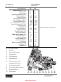
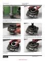
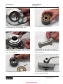
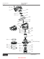
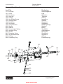
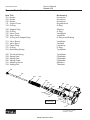
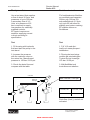
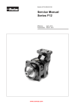
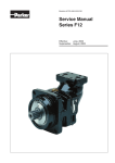
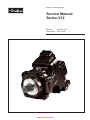
Bulletin HY30-5506-M1/UK
Service Manual
Series V12
Effective:
October, 2011
Supersedes: June, 2006
www.comoso.com
Service Manual
Series V12
HY30-5506-M1/UK
List of contents
Page
Specifications and cross section................................................................ 3
Assembling shaft package ...................................................................4 - 5
Assembling cylinder barrel, joint shaft and cover....................................... 5
Assembling control cover........................................................................... 6
Assembling end cap..............................................................................7-10
Assembling complete unit................................................................... 11-13
End-cap location ...................................................................................... 14
Parts specification and split view.......................................................15 - 19
Seal kit specification................................................................................. 20
Test procedure.......................................................................................... 21
Gauge and pilot ports AC and AH control................................................. 22
Gauge and pilot ports EO and EP control................................................ 23
Gauge and pilot ports HO and HP control................................................ 24
Conversion factors
1 kg
1 N
1 bar
1 l
1 l
1 cm3
1 m
1 mm
1 °C !
= 2.2046 lb
= 0.22481 lbf
= 14.504 psi
= 0.21997 UK gallon
= 0.26417 US gallon
= 0.061024 in3
= 3.2808 feet
= 0.03937 in
= 1.8°F + 32
WARNING
FAILURE OR IMPROPER SELECTION OR IMPROPER USE OF THE PRODUCTS AND/OR SYSTEMS DESCRIBED
HEREIN OR RELATED ITEMS CAN CAUSE DEATH, PERSONAL INJURY AND PROPERTY DAMAGE.
This document and other information from Parker Hannifin Corporation, its subsidiaries and authorized distributors provide
product and/or system options for further investigation by users having technical expertise. It is important that you analyze all
aspects of your application, including consequences of any failure, and review the information concerning the product or system in the current product catalogue. Due to the variety of operating conditions and applications for these products or systems,
the user, through its own analysis and testing, is solely responsible for making the final selection of the products and systems
and assuring that all performance, safety and warning requirements of the application are met.
The products described herein, including without limitation, product features, specifications, designs, availability and pricing,
are subject to change by Parker Hannifin Corporation and its subsidiaries at any time without notice.
Offer of Sale
Please contact your Parker representation for a detailed ”Offer of Sale”.
2
www.comoso.com
Parker Hannifin
Pump and Motor Division
Trollhättan, Sweden
Service Manual
Series V12
HY30-5506-M1/UK
Specifications
V12 frame size
Displacement [cm³/rev]
at 35° (max)
at 6,5° (min)
Operating pressure [bar]
max intermittent ¹)
max continuous
Operating speed [rpm]
max intermittent at 35° ¹)
max continuous at 35°
max intermittent at 6.5°-20° ¹)
max continuous at 6.5°-20°
min continuous
Flow [l/min]
max intermittent ¹)
max continuous
Output torque [Nm]
at 100 bar (theor.)
Max output power [kW]
max intermittent ¹)
max continuous
Corner power [kW]
max intermittent ¹)
continuous
Mass moment of inertia
(x10-3) [kg m2]
Weight [kg]
60
80
60
12
80
16
480
420
480
420
4400
3600
7000
5600
50
4000
3100
6250
5000
50
265
215
320
250
95
127
150
95
175
105
335
235
400
280
3.1
28
4.4
33
¹) Max 6 seconds in any one minute.
V12 cross section
1. End cap
2.
Servo control valve
3.
Setting piston
4.
Valve segment
5.
Cylinder barrel
6.
Spherical piston with
laminated piston ring
7.
Synchronizing shaft
8.
Heavy-duty roller bearings
9.
Bearing housing
10. Output shaft
1
2
3
3
www.comoso.com
4
5
6
7
8
9
Parker Hannifin
Pump and Motor Division
Trollhättan, Sweden
10
Service Manual
Series V12
HY30-5506-M1/UK
Assembling, shaft package
1. Press down the big tappered roller bearing
and the inner ring for the roller bearing in two
steps. Note! On V12-060 there is a distance
between the bearings.
4. Assemble the shim.
2. Press down the roller bearing with the text
upwards into the flange and assemble it on
the shaft package.
5. Assemble the retaining ring. Make sure
it is all the way into the groove. Check the
pre-load of the bearings, not to tight and no
back-lash.
3. Assemble the bearing ring with the text
downwards.
6. Assemble the O-ring.
4
www.comoso.com
Parker Hannifin
Pump and Motor Division
Trollhättan, Sweden
Service Manual
Series V12
HY30-5506-M1/UK
Assembling, shaft package, cylinder barrel, joint shaft and cover
7. Press down the shafts seal in the seal carrier and assemble the retaining ring.
10. Assemble the sliding plate.
8. Assemble the seal carrier with shaft seal
and the retaining ring. Make sure it is all the
way into the groove.
11. Assemble the joint rollers on the joint
shaft. Make sure the step on the joint rollers
is fitted inwards.
9. Assemble the guide pins.
12. Assemble the displacement setting screw,
seal nut and the O-ring.
5
www.comoso.com
Parker Hannifin
Pump and Motor Division
Trollhättan, Sweden
Service Manual
Series V12
HY30-5506-M1/UK
Assembling, control cover
DIN 38±8 Nm
SAE 25±5 Nm
DIN 13±3 Nm
(AHI-I)
DIN 38±8 Nm
SAE 25±5 Nm
13. Assemble the O-rings and plugs that are
required for the specific control cover. AHcontrol is shown in the picture.
16. Assemble the hexagon plug.
12±3 Nm
Narrow side
14. Assemble the control piston in the AHhousing.
17. Assemble the AH-housing. The narrow
side against X5.
15. Assemble the O-ring.
18. Put some greas on the guide pin and
assemble it in the control cover.
6
www.comoso.com
Parker Hannifin
Pump and Motor Division
Trollhättan, Sweden
Service Manual
Series V12
HY30-5506-M1/UK
Assembling, end cap
DIN 38±8 Nm
SAE 25±5 Nm
19. Assemble the hexagon plugs.
22. Assemble the companion pin in the setting piston. Make sure the location hole is
against the control cover side.
20. Assemble the adjusting screw and seal
nut.
23. Assemble the set screw with the pointed
end. Make sure that it hits the location hole in
the companion pin.
Control cover side
21. Assemble the setting piston in the end
cap. Make sure the thread is against the control cover side.
24. Torque the set screw to 14±4 Nm.
7
www.comoso.com
Parker Hannifin
Pump and Motor Division
Trollhättan, Sweden
Service Manual
Series V12
HY30-5506-M1/UK
Assembling, end cap
25. Assemble the set screw with the flat end.
28. Assemble the modulating spring.
26. Torque the set screw to 26±6 Nm. Move
the companion pin back and forward to make
sure it moves smooth.
29. Assemble the spring seat.
27. Assemble the spring guide. Use a long
allen key to locate the spring guide.
30. Assemble the threshold spring.
8
www.comoso.com
Parker Hannifin
Pump and Motor Division
Trollhättan, Sweden
Service Manual
Series V12
HY30-5506-M1/UK
Assembling, end cap
31. Assemble the spring seat.
34. Assemble the valve cones.
32. Assemble the nozzles and torque them to
1,2±0,2 Nm.
35. Assemble the valve guides assy. Carefully tap them down with a hammer.
33. Assemble the valve sleeve assy. Make
sure the spool hits the guide hole in the
spring seat.
36. Assemble the nozzles and torque them to
1,2±0,2 Nm.
9
www.comoso.com
Parker Hannifin
Pump and Motor Division
Trollhättan, Sweden
Service Manual
Series V12
HY30-5506-M1/UK
Assembling, end cap
37. Assemble the control cover assy. Make
sure the O-rings are in correct position.
40. Torque the screws to 65±10 Nm for
V12-60 -- 110, 105±20 Nm for V12-160.
38. Torque the screws to 65±10 Nm for
V12-60 -- 110, 105±20 Nm for V12-160.
41. Assemble the valve segment in the end
cap. The slot in the valve segment against
the cover side.
39. Assemble the cover assy. Make sure not
to damage the O-ring.
10
www.comoso.com
Parker Hannifin
Pump and Motor Division
Trollhättan, Sweden
Service Manual
Series V12
HY30-5506-M1/UK
Assembling, complete unit
42. Place the bearing package in a fixture.
Assemble the compression spring.
45. Assemble the pistons and line them up as
shown in picture.
43. Assemble the guide pin.
46. Assemble the joint shaft with joint rollers.
Add some grease to keep the joint rollers in
place.
44. Assemble the support pin.
47. Assemble the support pin. Use a lot of
grease to keep it in place.
11
www.comoso.com
Parker Hannifin
Pump and Motor Division
Trollhättan, Sweden
Service Manual
Series V12
HY30-5506-M1/UK
Assembling, complete unit
48. Assemble the cylinder barrel. Make sure
that all rollers are in place.
51. Assemble the bearing housing. Carefully
knock it down with a plastic hammer. Secure
the housing by assembling one screw.
49. Make sure the support pin is in correct
position by using a steel wire.
52. Assemble the gasket and lubricate it with
hydraulic oil.
50. Assemble the gasket and lubricate it with
hydraulic oil.
53. Assemble the end cap assy. Mind your
fingers, don't squeeze them.
Refer to page 14 for end cap location.
12
www.comoso.com
Parker Hannifin
Pump and Motor Division
Trollhättan, Sweden
Service Manual
Series V12
HY30-5506-M1/UK
Assembling, complete unit
54. Assemble the screws and torque the
screws to 65±10 Nm for V12-60/80 and
105±20 Nm for V12-110/160.
55. Assemble the screws and torque the
screws to 65±10 Nm for V12-60/80 and
105±20 Nm for V12-110/160.
13
www.comoso.com
Parker Hannifin
Pump and Motor Division
Trollhättan, Sweden
Service Manual
Series V12
HY30-5506-M1/UK
End cap location
AC and AH control shold be assembled with the control cover at the maximum side.
Minimum
side
Maximum
side
EO and EP control shold be assembled with the control cover at the minimum side.
Minimum
side
Maximum
side
HO and HP control shold be assembled with the control cover at the minimum side.
Minimum
side
Maximum
side
14
www.comoso.com
Parker Hannifin
Pump and Motor Division
Trollhättan, Sweden
Service Manual
Series V12
HY30-5506-M1/UK
General Parts
Item
Title
Benämning
111
211
225
227
227
229
231
233
237
245
246
311
411
413
415
420
424
433
434
440
447
448
449
451
453
454
455
460
465
470
476
476
478
493
495
501
510
End Cap Bearing Housing
O-Ring
Gasket
O-Ring
O-Ring
Seal Carrier
Shaft Seal
Retaining Ring Seal Washer
Hex Socket Screw
Shaft
Cylinder Barrel
Guide Pin
Needle Bearing Valve Segment
Sliding Plate
Compression Spring
Guide Pin
Piston Assy
Joint Shaft
Joint Roller
Support Pin
Spring Pin
Pin
Retaining ring Joint Coupling
Tap Rol Bearing
Spacer Sleeve
Cyl Bearing
Spacer Washer Spacer Washer Retaining Ring Hex Socket Screw
Gasket
Bearing Housing
Hexagon Plug
Ansl. Block
Lagerhus
O-Ring
Packning
O-Ring
O-Ring
Tätringshållare
Tätningsring
Spårring
Tätbricka
Insexskruv
Axel
Cylindertrumma
Styrstift
Nålbussning
Ventilsegment
Glidplatta
Tryckfjäder
Styrpinne
Kolv KPL
Synkroniseringsaxel
Rulle
Stödpinne
Rörpinne
Pinne Spårring Medbringare
Kon Rullager Distanshylsa
Cyl Lager Distansbricka Distansbricka Spårring Insexskruv
Packning
Lagerhus Insexpropp
15
www.comoso.com
Parker Hannifin
Pump and Motor Division
Trollhättan, Sweden
Service Manual
Series V12
HY30-5506-M1/UK
Split view
493
420
111
424
413
415
411
495
449
448
447
449
510
227
434
501
454
451
453
455
440
433
311
227
460
465 (V12-60 only)
245
246
229
211
470
246
476
476
478
233
225
231
237
16
www.comoso.com
Parker Hannifin
Pump and Motor Division
Trollhättan, Sweden
Service Manual
Series V12
HY30-5506-M1/UK
General Parts End Cap
ItemTitle
111 End Cap
121Cover
122 Set Screw
123 Seal Nut
125O-Ring
126 Hex Socket Screw
133 Setting Piston
134 Set Screw
135 Set Screw
136 Companion Pin
822Shuttle
823Washer
824 Compression Spring
825 Hexagon Plug
835 Nozzle
841 Protective Cover
842 Hex Socket Screw
843O-Ring
844 Expanding Plug
Benämning
Anslutningsblock
Lock
Ställskruv
Tätmutter
O-Ring
Insexskruv
Ställkolv
Stoppskruv
Stoppskruv
Medbringartapp
Spolkolv
Bricka
Tryckfjäder
Sexkantpropp
Munstycke
Skyddslock
Insexskruv
O-Ring
Expanderplugg
111
126
123
121
136
125
134
844
835
133
122
842
841
843
844
822
823
824
825
17
www.comoso.com
Parker Hannifin
Pump and Motor Division
Trollhättan, Sweden
135
Service Manual
Series V12
HY30-5506-M1/UK
General Parts Control
ItemTitle
701 Nozzle
703 Nozzle
705 Nozzle
711 Control Cover 719O-Ring
Benämning
Munstycke
Munstycke Munstycke Regulatorlock O-Ring
720
729
735
736
737
Support Ring
O-Ring Valve Cone
Valve Guide
O-Ring with Support Ring
Stödring
O-Ring
Ventilkägla
Ventilsäte O-Ring med Stödring
771
772
774
775
781
Valve Sleeve
Valve Spool
Piston Ring O-Ring Modulating Spring
Ventilfoder
Ventilslid
Lamellring O-Ring Tryckfjäder
782
783
784
785
791
793
Threshold Spring
Spring Seat
Spring Seat
Spring Guide
Adjusting Screw
Sealing Nut
Tryckfjäder
Fjädersäte
Fjädersäte
Fjädersäte
Ställskruv
Tätmutter
793
791
785
781
784
782
783
735
736
701
737
729
703
774
775
771
Assembled in
the end cap
720
719
705
717
772
711
18
www.comoso.com
Parker Hannifin
Pump and Motor Division
Trollhättan, Sweden
Service Manual
Series V12
HY30-5506-M1/UK
General Parts Controls
747
746
744
742
Item Title
741 AH Housing
742O-Ring
743 Hex S Screw
744 Control Piston
746 Piston Seal
747 Guide Pin
741
743
763
762
761
Item Title
761Solenoid
762O-Ring
763 Guide Pin
DIN and SAE: M10x1
722
723
711
724
713
726
714
Item 711
713
714
722
723
724
726
Title
Control Cover
Set Screw
Seal Nut
Seal Plug
Hexagon Plug
Hexagon Plug
Hexagon Plug
DIN: M14x1,5
SAE: 9/16 - UNF-2B
19
www.comoso.com
Parker Hannifin
Pump and Motor Division
Trollhättan, Sweden
Service Manual
Series V12
HY30-5506-M1/UK
Seal Kit Specification
775
719
720
717
729
737
742
746
125
123
762
843
495
V12-0603794856
V12-0803794858
V12-1103795372
V12-1603796388
227
For N-type flange
227
224
245
229
229
233
225
20
www.comoso.com
Parker Hannifin
Pump and Motor Division
Trollhättan, Sweden
Service Manual
Series V12
HY30-5506-M1/UK
Test procedure
Funktionskontroll
Use a test stand that supplies
a flow of about 30 l/min. and
pressures of up to 300 bar.
A secondary flow of 3-5
l/min. at a pressure of 25
bar is required to supply
low pressure for externally
supplied controls.
EP control requires an
amplifier supplying correct
current according to
specification.
För funktionskontroll behövs
en provbänk med kapacitet
30l/min och 300 bar. Ett
sekundärflöde på 3-5 l/min
och tryck 25 bar krävs för
ställdon med extern matning.
EP ställdon kräver en
förstärkare.
Test
Test
1. Fill housing with hydraulic
fluid and start the pump in the
test stand.
1. Fyll V12 med olja i
huset och starta pumpen i
testbänken.
2. Increase the pressure
with the restrictor valve on
the return line. Max allowed
pressure is 150 bar / 2150 psi.
2. Öka trycket med strypventilen på returledningen.
Trycket får inte överstiga
150 bar / 2150 psi.
3. Check the drain flow and
compare with the table.
3. Mät läckflödet och
kontrollera mot tabellen
~ 30 l/min
Servo oil
Servolja
V12
Max 150 bar / 2150 psi
Max 220 bar / 3100 psi
Pump
V12-60, -80
V12-110, -160
3.0
4.0
Drain flow (l/min.), control not
activated.
21
www.comoso.com
Parker Hannifin
Pump and Motor Division
Trollhättan, Sweden
Service Manual
Series V12
HY30-5506-M1/UK
Gauge/Pilot ports (AC and AH control)
X1
Setting piston pressure (increasing displ.)
X2
Servo supply pressure (after orifice)
X4
Servo supply pressure (before orifice)
X5
External pilot pressure
X6
Setting piston pressure (decreasing displ.)
X7
Override pressure (only AH control)
Ports are:
-
M14x1.5 (ISO and cartridge versions)
9
-
/16"-18 O-ring boss (SAE version)
Displacement
(setting piston position)
Override
engaged
Displacement
(setting piston position)
Min threshold
pressure
Override
engaged
Max
Min threshold
pressure
Max
Optional
modulating
pressure
Optional
modulating
pressure
Max
threshold
pressure
Min
Max
threshold
pressure
Min
Ps
Threshold
pressure
Δp
Modul.
pressure
X4
X2
System
pressure
Ps
Threshold
pressure
A
X4
Δp
Modul.
pressure
X2
X7
Max
A
Max
Min
X6
X1
Min
B
X6
ACI 01 I schematic (spool in a balanced, mid-pos.)
X4
X2
System
pressure
X1
B
AHI 01 I schematic (spool in a balanced, mid-pos.)
A
X4
X5
X2
X5
X7
Max
A
Max
Min
Min
X6
X1
B
ACE 01 I schematic (spool in a balanced, mid-pos.)
X6
X1
B
AHE 01 I schematic (spool in a balanced, mid-pos.)
22
www.comoso.com
Parker Hannifin
Pump and Motor Division
Trollhättan, Sweden
Service Manual
Series V12
HY30-5506-M1/UK
Gauge/Pilot ports (EO and EP control)
X1
Setting piston pressure (max-to-min, EO)
X1
Setting piston pressure (decreasing displ. EP)
X2
Servo supply pressure (after orifice)
X4
Servo supply pressure (before orifice)
X6
Setting piston pressure (min-to-max, EO)
X6
Setting piston pressure (increasing displ. EP)
Ports are:
-
M14x1.5 (ISO and cartridge versions)
9
-
/16"-18 O-ring boss (SAE version)
Displacement
(setting piston position)
Displacement
(setting piston position)
Max
Max
Min threshold
current
Max threshold
current
Min
Min
Solenoid
current
Is
Is
Solenoid
current
ΔI
Threshold Modulating
current
current
Threshold
current
X4
X2
A
X4
X2
Min
A
Min
Max
X6
X1
Max
B
EOH 01 I schematic (non-activated solenoid)
X4
X2
X6
X1
B
EPH 01 I schematic (spool in balanced, mid-pos.)
A
X4
X2
Min
A
Min
Max
Max
X6
X1
B
EOH 01 E schematic (non-activated solenoid)
X6
X1
B
EPH 01 E schematic (spool in balanced, mid-pos.)
23
www.comoso.com
Parker Hannifin
Pump and Motor Division
Trollhättan, Sweden
Service Manual
Series V12
HY30-5506-M1/UK
Gauge/Pilot ports (HO and HP control)
X1
Setting piston pressure (max-to-min, HO)
X1
Setting piston pressure (decreasing displ. HP)
X2
Servo supply pressure (after orifice)
X4
Servo supply pressure (before orifice)
X5
External pilot pressure (max 100 bar)
X6
Setting piston pressure (min-to-max, HO)
X6
Setting piston pressure (increasing displ. HP)
Ports are:
-
M14x1.5 (ISO and cartridge versions)
9
-
/16"-18 O-ring boss (SAE version)
Displacement
(setting piston position)
Displacement
(setting piston position)
Max
Max
Min threshold
pressure
Min threshold
pressure
Max threshold
pressure
Max threshold
pressure
Min
Min
Ps
Threshold
press. (min)
X4
Pilot
pressure
Adjustment
range
X2
Pilot
pressure
Δp
Ps
Threshold
pressure
Modulating
pressure
X4
A
X2
A
X5
X5
Min
Min
Max
Max
X6
X1
B
HO S 01 I schematic (X5 not pressurized)
X4
X2
X6
A
X5
X1
X4
X2
Min
Max
X1
A
X5
Min
X6
B
HP S 01 I schematic (spool in a balanced, mid-pos.)
Max
B
HO S 01 E schematic (X5 not pressurized)
X6
X1
B
HP S 01 E schematic (spool in a balanced, mid-pos.)
24
www.comoso.com
Parker Hannifin
Pump and Motor Division
Trollhättan, Sweden
HY30-5506-M1/UK
Service Manual
Series V12
25
www.comoso.com
Parker Hannifin
Pump and Motor Division
Trollhättan, Sweden
HY30-5506-M1/UK
Service Manual
Series V12
26
www.comoso.com
Parker Hannifin
Pump and Motor Division
Trollhättan, Sweden
HY30-5506-M1/UK
Service Manual
Series V12
27
www.comoso.com
Parker Hannifin
Pump and Motor Division
Trollhättan, Sweden
Parker Hannifin
Pump and Motor Division
Flygmotorvägen 2
SE-461 82 Trollhättan
Sweden
Tel: +46 (0)520 40 45 00
Fax: +46 (0)520 371 05
www.parker.com
www.comoso.com