1
P/N 7711017
NOTE: The programmable run-time
has been preset for
10 Minutes
Instructions to change this
setting are located on page 7.
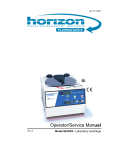
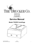
Model 755V
Shown
Model 755 - 24-Place, 755V - 24-Place, 755 - 12-Place, 755 Microplate
Operator’s / Service Manual
Rev. D
2
Table of Contents
Model Description Supplied Equip.
Available Features Specifications Control Panel Setup Location Initial Setup Procedure Additional Setup Procedure Operation Balanced Loads Tube Holder Configurations Force Chart—12 place Care and Preventative Service Rotor Removal and Installation Safety Emergency Rotor Chamber Entry Troubleshooting Available Accessories Warranty pg. 3
pg. 4
pg. 5
pg. 6-7
pg. 8
pg. 9
pg. 9-10
pg. 10-11
pg. 11
pg. 12
pg. 13
pg. 14
pg. 15
pg. 16
pg. 17
pg. 17
pg. 18
pg. 19-20
pg. 24
WARNING: Care should be taken when handling substances that are known to be toxic,
radioactive or contaminated with pathogenic microorganisms when using this centrifuge for
the safety of both the operator and service personnel. When Risk Group II materials are
used (as identified in the World Health Organization “Laboratory Bio-Safety Manual”), a
Bio-Seal should be employed. More than one level of protection must be provided in the
case of materials of a higher group. The use of flammable or explosive materials as well
as those materials which chemically react vigorously is prohibited.
Model Description:
The Horizon Model 755 is a continuous-duty, electronically-controlled, single or variable-speed, horizontal
laboratory centrifuge with a lid safety interlock system. The unit is controlled by an electronic push-button
timer that is variable from 1 to 30 minutes, for precise spin times and ease of use. Samples can be safely
viewed through the transparent lid. The imbalance detection system safely terminates a run cycle in the event
that a severely imbalanced load is present. Entry into the machine is restricted during operation by the safety
interlock system. The Horizon features a lighted control panel that displays the status of the machine, easily
viewable from a distance. Finally, a cycle counter keeps a count of the total number of machine runs for
servicing and maintenance records.
Intended Use:
General purpose laboratory centrifuge for sample preparation.
3
Supplied Equipment*:
The following items come standard with each Horizon 755V-24 Centrifuge:
1. One (1) six-place horizontal rotor
2. Six (6) 100 mm four-place tube carriers 3. One (1) Operator's Manual (not shown) 4. One (1) Tutorial CD (not shown)
Optional:
• 50mL single-place tube carrier • Carrier cap 1.
p/n 7786022
p/n 7713023
p/n 7713037
p/n 7713035
2.
* The rotor and rotor accessories are rated for a rotation frequency of 3500 RPM (a force of 2100 xg).
Supplied Equipment*:
The following items come standard with each Horizon 755V-12 Centrifuge:
1.
2.
3.
4.
5.
6.
One (1) Horizon centrifuge
One (1) twelve-place horizontal rotor Twelve (12) 100 mm test tube holders
Twelve (12) 125mm test tube holders Twelve (12) 75 mm test tube
One (1) Operator’s manual
1.
p/n 7786024
p/n 7713031
p/n 7713032
p/n 7713033
2.
3.
4.
5.
P/N 7711017
NOTE: The programmable run-time
has been preset for
10 Minutes
Instructions to change this
setting are located on page 7.
Model 755V
Shown
NOTE: Your centrifuge may
have been shipped with additional
or alternate accessories.
* The rotor and rotor accessories are rated for a rotation frequency of 4,000 RPM, (a force of 2450 xg with the 100mm tube holders).
Model 755 - 24-Place, 755V - 24-Place, 755 - 12-Place, 755 Microplate
Operator’s / Service Manual
Rev. A
Supplied Equipment*:
The following items come standard with each Horizon 755 Microplate Centrifuge:
1. One (1) Microplate rotor 2. One (1) Operator’s manual 1.
p/n 7786051
p/n 7711017
2.
P/N 7711017
NOTE: The programmable run-time
has been preset for
10 Minutes
Instructions to change this
setting are located on page 7.
Model 755V
Shown
Model 755 - 24-Place, 755V - 24-Place, 755 - 12-Place, 755 Microplate
* This rotor is rated for a rotation frequency of 1500 RPM.
Operator’s / Service Manual
Rev. A
4
Available Features:
• Swing-out horizontal rotor design incorporating a unique test tube holder that produces horizontally
separated samples while requiring no additional parts, (optional fixed-angle rotors are also available)
• Variable-speed (Model 755V, see speed range below)
• Cool-Flow air flow design that prevents overheating of samples
• Heavy gauge steel construction for safety and durability
• Lid safety switch that prevents the centrifuge from operating unless the lid is closed and latched
• Removable rotor for easy cleaning
• Locking lid that allows entry into the centrifuge only after the rotor has completely stopped
• Brushless DC Motor; requires no routine maintenance, cool running
• Clear lid for safe observation of samples and optical calibration of speed
• Electronically controlled timed operation variable from 1 to 30 minutes
• Push-button operation
• Indicator lights:
‘RUN’ green -lights when power is applied to the motor
‘LATCH’ yellow -lights when the lid is closed and latched
‘UNLOCKED’ red -lights when the lock system is deactivated
• Cycle counter to monitor machine usage
• Audible indicator at the end of each run
5
Specifications: 12-Place
Speed Range (Model 755V):
755V w/12-Place Horizontal Rotor: 500 to 3,200 (± 100) RPM*
755V w/Fixed-Angle Rotors: 500 to 4,000 (± 100) RPM*
Max Speed (Model 755): (This speed is set by the factory, see page 7)
with 12-Place Horizontal Rotor 3,600 (± 100) RPM
with Fixed-Angle Rotors 3,600 (± 100) RPM
Maximum capacity:
12-Place Horizontal Rotor: 180 mL (12 x 15 mL)
20-Place Fixed-Angle Rotor: 300 mL (20 x 15 mL)
Overall Dimensions (H x W x D): Centrifuge Motor: Nominal Acceleration Time: Nominal Braking Time: Protection Breaker: Timer (electronic): Current Requirement: Voltage Requirement: Frequency: Weight: 9 in. x 14.5 in. x 17 in.
1/2 H.P. Brushless DC
30 seconds
15 seconds
4 Amp. re-settable
1 to 30 min ± 1%
2.0 A @ 115 VAC
or 1.0 A @ 230 VAC
115 or 230 (±10%) Volts AC
50 / 60 Hz
39 lbs.
* Any use other than those specified by the manufacturer is explicitly prohibited.
Maximum speed shown is for the given rotor with 100mm red tube holders. The use of other tube holders will alter the maximum speed.
Specifications: 24-Place
Speed Range (V.S.V.): 755V w/24-Place Horizontal Rotor: 755V w/20-Place Fixed-Angle Rotors: Force Range (variable speed version): Single Speed Setting:
(This speed is set by the factory, see page 7) Force (@ 3000RPM): Maximum capacity: Overall Dimensions (H x W x D): Centrifuge Motor: Nominal Acceleration Time: Nominal Braking Time: Protection Breaker: Timer (electronic): Current Requirement: Voltage Requirement: Frequency: Weight: 500 to 3,150 (± 5%) RPM
3,150 (± 100) RPM*
3,200 (± 100) RPM*
45 to 1,760 (± 10%) xg
3,000 (± 5%) RPM
1,600 x g
240 mL (24 x 10 mL)*
300 mL (6 x 50 mL)*
9 in. x 14.5 in. x 17 in.
1/2 H.P. Brushless DC
30 seconds
15 seconds
4 Amp. re-settable
1 to 30 min ± 1%
2.0 @ 115 VAC
or 1.0 A @ 230 VAC
115 or 230 (±10%) Volts AC
50 / 60 Hz
39 lbs.
6
Specifications: Microplate Rotor
Speed: Force: Maximum capacity: 1500RPM (±100) RPM
322 (±50) xg
200g
Overall Dimensions (H x W x D): Centrifuge Motor: Nominal Acceleration Time: Nominal Deceleration (Breaking) Time: Protection Breaker: Timer (electronic): Current Requirement: Voltage Requirement: Frequency: Weight: 9 in. x 14.5 in. x 17 in.
½ H.P. Brushless DC
65 seconds
50 seconds
4 Amp. re-settable
1 to 30 min ±1%
2.0 A @ 115 VAC
or 1.0 A @ 230 VAC
115 or 230 (±10%) Volts AC
50 / 60 Hz
39 lbs.
Any use other than those specified by the manufacturer is explicitly prohibited.
* Maximum speed density is 1.15 grams/mL (water density = 1.00 grams/mL).
7
Control Panel:
Lid Safety
Switch
‘RUN’
Indicator
‘LATCH’
Indicator
Speed
Control
(755V Only)
‘UNLOCKED’
Indicator
‘START’
Button
‘OPEN/
EMERGENCY
STOP’
Button
Cycle
Counter
Power
(On/Off)
Button
‘RUN’
Indicator
Lights up when the
machine is in operation,
(power is being applied
to the motor).
‘LATCH’
Indicator
Lights up when the lid
has been closed and
latched properly.
‘UNLOCKED’
Indicator
Lights up to indicate that
the locking mechanism
has been deactivated,
allowing access to the
rotor chamber.
Power
(On/Off)
Button
This button controls the
power to the centrifuge.
The power is on when
the button is illuminated.
Speed
Control
(755V
ONLY)
Use this input to set the
running speed of the
centrifuge. The speed
may also be adjusted
while the centrifuge is
running.
‘START’
Button
Begins a new run, (the lid
must be closed, see pg. 6).
‘OPEN /
EMERGENCY
STOP’
Button
Allows access into the
rotor chamber by
disengaging the locking
mechanism. Entry is only
permitted when the rotor is
stopped. Pressing this
button during operation will
terminate the run and
unlock the lid after the
rotor has come to a stop.
Cycle
Counter
This counter increments
once for each run of the
centrifuge. This count is
used for both warranty
purposes and for routine
maintenance.
Lid
Safety
Switch
The lid safety switch
prevents the centrifuge
from operating while the lid
is open. If the knob is not
turned completely
clockwise to its stop
position the centrifuge
cannot operate.
Programming functions are
accessed by first opening
the lid safety switch.
8
Setup Location:
1. Unpack the centrifuge and verify that all of the supplied equipment is present.
2. Choose a setup location which meets the following criteria:
a) A bench top clearance height of 24” is required in order to open the lid.
b) The clearance envelope is the space around the centrifuge which is
required for safety. Choose a setup location which will allow for a
clearance envelope of at least 30” x 30” (with the centrifuge at the
center). No person or hazardous material shall be permitted in the
clearance envelope during operation. The operator time within the
envelope shall be limited to the time necessary for loading, unloading and
centrifuge operation only.
c) Proper ventilation is necessary to prevent the overheating of samples as
well as premature failure of the centrifuge. Choose an area which will
allow unencumbered air flow.
d) No adjustment is necessary for leveling the centrifuge, however,
the surface should be flat and level.
e) Be sure the outlet is always within reach as the line cord is
the means of emergency disconnection!
Initial Setup Procedure:
If any problems are found during the initial setup procedure, refer to the
troubleshooting section on page 12.
1. Plug the line cord into the rear of the centrifuge. Plug the other end into an
approved electrical outlet. For electrical safety, the unit must always be
properly grounded.
2. Engage the power button on the front of the centrifuge (lower left-hand
side). The button will be illuminated when it is activated.
3. For safety purposes, the locking system is always activated. To
deactivate the system (in order to insert or retrieve samples) press the
‘OPEN / EMERGENCY STOP’ button on the control panel. The
‘UNLOCKED’ indicator light should illuminate. If it does not, refer to page
12 on troubleshooting. The lid will be unlocked for 15 seconds after pushing
the ‘OPEN / EMERGENCY STOP’ button.
4. Turn the latch counter-clockwise and open the lid.
5. Spin the rotor by hand; check for free and level rotation. If the rotor does
not spin freely, refer to page 12 on troubleshooting.
6. Check the thumb screw in the middle of the rotor and make sure that it is tight.
7. Place the test tube carriers inside the rotor and verify that they are seated
properly.
8. Close the lid. Rotate the lid knob clockwise to its complete stop position.
The ’LATCH’ indicator light should be illuminated. If it is not, make sure that
the lid is latched properly. The centrifuge will not run unless the lid is
latched and the ’LATCH’ light is on.
(continued next page)
9
(Continued)
9. If this is a variable speed version, turn the speed control to MAX.
10. Turn the centrifuge on by pushing the ‘START’ button.
11. The ‘RUN’ indicator light will illuminate.
12. The unit will accelerate to its set speed.
13. Listen to the sound of the centrifuge. A smooth whirring sound should be
heard. If there are any loud or unusual sounds, stop the centrifuge by
pushing the ’OPEN / EMERGENCY STOP’ button immediately and refer
to page 12 on troubleshooting.
14. While the machine is running, try to turn the latch counter-clockwise.
Power may be cut to the motor but you should not be able to fully turn
the latch. If it is possible to turn the latch and open the lid while the unit
is running, contact your authorized dealer or The Drucker Company.
Close and latch the lid.
15. Push the ‘OPEN / EMERGENCY STOP’ button. The ‘RUN’ indicator
light should go out and the motor should slow to a stop.
16. The lid should remain locked until the rotor has stopped. If the machine
unlocks prematurely, contact your authorized dealer or The Drucker
Company. Once the rotor has stopped, a beeper will sound and the
interlock system will become disengaged for sixty (60) seconds. The
‘UNLOCKED’ indicator light will be illuminated during this time.
17. To gain entry into the centrifuge after this period has ended, simply press
the ‘OPEN / EMERGENCY STOP’ button. The lid will unlock for fifteen
(15) additional seconds. Repeat if necessary.
After the centrifuge has passed this procedure,
it is ready for operation.
If you would like to make adjustments to your machine’s
settings, please continue on to “Additional Set-Up Procedures”.
Additional Set-Up Procedures (Optional):
1. Verify the Run-Time Preset:
NOTE: The centrifuge must be plugged in and the lid must be opened to
access programming functions!
a. Push and hold the ‘START’ button for approximately three (3) seconds.
The ’LATCH’ indicator light will begin to flash; indicating program mode.
b. When you release the ‘START’ button, the ‘RUN’ indicator light will begin
to flash. Each flash of the ‘RUN’ indicator light represents one minute of
run time. If the time indicated is not desired, follow the instructions on
the rear of the centrifuge to change it.
(continued next page)
10
2. Change the Run-Time Preset:
NOTE: The centrifuge must be plugged in and the lid must be opened to
access programming functions!
a. b. c. d.
Push and hold both the ‘START’ and ’OPEN / EMERGENCY STOP’
buttons for approximately three (3) seconds. The ’LATCH’ indicator light
will begin to flash; indicating program mode. Release the two buttons.
Press the ‘START’ button once for each minute of desired run time.
The ‘RUN’ indicator light will flash once for each entered minute.
Press the ‘OPEN / EMERGENCY STOP’ button to save the change and
exit programming mode.
If desired, use the “verify the preset time” procedure to confirm that the
adjustment is correct.
Operation:
NOTE: Follow the initial setup procedure on page 5 before initial operation.
1. Plug the centrifuge into an approved 115 Volt A.C., 50/60 Hz. outlet.
2. Push the ‘OPEN / EMERGENCY STOP’ button and then open the lid.
3. Place the test tube samples into the tube carriers. Be sure to follow the rules for
balanced loads. See next page for assistance.
4. Close the lid and turn the lid knob clockwise to its complete stop position. The
’LATCH’ indicator light should turn on to indicate that the latch is closed properly.
If the lid knob is not completely latched, the ‘LATCH’ indicator light will not turn
on and the centrifuge will not operate!
5. Turn on the machine by pushing the ‘START’ button on the control panel.
6. The centrifuge should begin to spin. The ‘RUN’ indicator light should illuminate.
IF A PROBLEM IS FOUND DURING A SPIN THAT REQUIRES THE CENTRIFUGE
TO SHUT DOWN, PRESS THE ‘OPEN / EMERGENCY STOP’ BUTTON !
7. The run indicator light will begin to flash when one minute remains in the cycle.
8. After time has elapsed, the ‘RUN’ indicator light will extinguish and the rotor will
brake to a complete stop.
9. The ‘UNLOCKED’ indicator light will illuminate, a beeper will sound and the locking mechanism will disengage allowing entry into the rotor chamber. If it does not, refer to page 12 on troubleshooting.
10. Turn the lid knob counter-clockwise and open the lid.
11. Remove the samples.
12. If the machine re-locks before the samples are removed, press the ‘OPEN / EMERGENCY STOP’ button to unlock the lid for an additional fifteen (15) seconds. Repeat if necessary.
11
BALANCED LOADS
Your centrifuge must contain a balanced load in order to work properly.
To ensure that the load is balanced, keep these rules in mind when
inserting test tube samples:
1. 2. 3. Opposing tube carriers must be identical.
Opposing tube carriers must be empty or loaded with an equal number of
equally weighted samples.
If an odd number of samples is to be spun, use a water-filled tube to mate
with the unpaired one.
Note: The 755 is designed to detect serious out-of-balance situations and will
safely terminate a run if one is detected. The 755 will cut power to the motor
and wait for the rotor to stop spinning before unlocking. The load should be
balanced before an attempt is made to re-run.
4. When loading tubes into opposing
carriers, the carriers will be balanced
when the tubes are loaded diagonally
from one another. See the illustration
to the right.
Note: When loading tubes that are
longer than 100mm in length, the
maximum capacity is two (2) tubes
per carrier. Place these longer tubes
in the right-hand side of each carrier.
Note: When spinning glass tubes in
the 4-place carrier, it is recommended
that the 0.25” tube cushion (p/n 9150)
be placed in the bottom of the carrier.
755-24 Shown
12
Tube Holder Configurations: 12-Place or Fixed Angle only
Your Horizon Model 755 centrifuge can spin various test tube sizes ranging from
1.5mL to 15mL, (up to 125mm, (4.9 in.) in length), with the appropriate accessories. Use the following chart and drawing to determine which tube holder and
cushion combination should be used with your application.
DIRECTIONS:
1. 2. 3. Compare the tube to be spun with the four boxes shown below.
Find the box that most closely matches the tube’s length. NOTE: The tube
length with its stopper or cap must be shorter then the chosen box or the tube
will not fit properly in the tube holder.
Match the letter from the chosen box with one of the configurations shown.
For Example: A tube is found to be as long as box B. Accordingly,
we can use a 125 mm tube holder with a 1525 cushion or a 100mm
tube holder with no cushion, (configuration B).
A.
125mm
Tube Holder*
B.
B.
A.
BLACK
RED
BLACK
125mm Tube
Holder* with
1525 cushion*
100mm
Tube Holder
or
C.
D.
C.
D.
RED
GREEN
100mm
Tube
Holder
with
1525
cushion*
75mm
Tube
Holder*
GREEN
BLUE
75mm Tube
Holder*
with 1525
cushion*
* This part is available as an accessory. Contact The Drucker Company for assistance.
13
Force Chart:
Force Chart:
Model755
755 Relative
Centrifugal
ForceForce
Chart Chart
Model
Relative
Centrifugal
12 Place Horizontal
20 Place Fixed Angle
24 Place Horizontal
2200
2000
1800
1600
RCF (xg)
1400
1200
1000
800
600
400
200
0
0
400
800
1200
1600
2000
2400
2800
3200
3600
4000
Spee d (RPM)
This chart
will allow
youset
to your
set your
Model
centrifuge
a desired
g-force
This chart
will allow
you to
Model
755755
centrifuge
to atodesired
g-force
byby
providing
the
appropriate
speed
for
the
rotor
you
are
using.
providing the appropriate speed for the rotor you are using.
Instructions for using this chart:
Instructions for using this chart:
Find the desired force on the left-hand column and then follow across at that
Find the
desired force on the left-hand column and then follow across at that
level until you meet the line for the tube holder you use. Follow this intersection
level point
until you
meet
thebottom
line forofthe
youthe
use.
Follow
this intersection
down
to the
thetube
chartholder
to reveal
speed
required
to produce
pointthat
down
to
the
bottom
of
the
chart
to
reveal
the
speed
required
to produce
force.
that force.
*
*
The graph shows the RCF, (relative centrifugal force), when using the 100mm red
tube holder.
of different
tube
holders and
/ or cushions
will alter
RCF. red
The graph
showsThe
theuse
RCF,
(relative
centrifugal
force),
when using
thethe
100mm
tube holder. The use of different tube holders and / or cushions will alter the RCF.
Page 14
14
Care and Preventative Service:
With proper care and maintenance, your Horizon centrifuge will provide years of
laboratory service. For proper care, the following steps should be taken:
1. Provide Adequate Ventilation: For cooling purposes, the Horizon draws in
ambient air through the rear of the lid and exhausts this air out the rear of the
base. Do not block the rear of the centrifuge as this will not allow the machine
to properly ventilate itself.
2. Always Spin Balanced Loads: Make certain that opposing tube holders are
filled with an equal volume sample or an equivalent weight water-filled tube.
The Horizon has a cushioned motor mounting design which, along with it’s
rubber feet, produces excellent vibration dampening. However, out-of-balance
loads may break glass test tubes and may produce unsatisfactory separation
results. Proper load balancing will improve sample separation and extend the
life of the centrifuge. Refer to page 8 on balanced loads for additional
information on balancing the load.
3. Keep the Tube Holders Clean: Small glass fragments left in the tube holder
after a tube breakage may adhere to the next test tube inserted in that holder.
When this tube is handled, these fragments may puncture protective gloves
and lacerate the operator's fingers or hand. Remaining fragments may provide
stress points on subsequent tubes and result in additional breakage. If a tube
breakage occurs, carefully remove the tube holder. Properly dispose of the sample
and tube fragments and thoroughly clean both the inside and outside of the tube
holder. Insert a new tube cushion (if necessary) and replace the tube holder in the rotor.
Note: Always follow the safety guidelines of your laboratory to properly clean up
and/or dispose of materials in the event that a substance known to be potentially
toxic, radioactive or contaminated with a pathogenic microorganism is spilt in
or on the centrifuge.
4. Motor and Electrical Maintenance: The Horizon uses a brushless DC motor.
It should not need servicing for the life of the centrifuge. The electrical
components are selected for high reliability and should not need service.
5. Keep the Rotor Chamber Clean: Every six months, or whenever there is a
tube breakage, (refer to the note in #3), it may be necessary to remove the
rotor and clean the rotor chamber. Follow the instructions on page 9 to remove
and re-install the rotor.
CAUTION DURING CLEANING: Once the lid has been opened, unplug the
line cord from the electrical outlet to eliminate the risk of electric shock during
cleaning.
The rotor chamber, rotor and accessories shall be thoroughly cleaned using
either isopropyl alcohol, soap and water or bleach. The use of Fully/Partially
Halogenated Hydrocarbons, Ketones, Esters and all other chemicals not
prescribed by the manufacturer may cause damage to the rotor and tube
holders and should not be used.
Apply cleaning solutions with a towel or cloth. Do not submerge the
centrifuge in water or other cleaning solutions as this will cause damage
and void your warranty!
6. Rotor and Tube Holders: It is recommended that the tube holders be replaced
after 24 months of use. Inspect tube holders regularly for cracks. If cracks are
discovered, replace immediately. Periodically check the thumb screw in the center
of the rotor to ensure that it remains tight.
(continued next page)
15
(Continued)
7. Remove Accessories Before Moving: All tube holders, samples, and
caps must be removed from the rotor chamber before transporting or
storing the centrifuge to prevent damage and injury.
Before using any cleaning or decontamination methods except those
recommended by the manufacturer, users should check with the manufacturer
that the proposed method will not damage the equipment. See page 15, Step 5,
for the recommended cleaning solutions.
Rotor Removal and Installation:
To remove the rotor:
1. Unlock the centrifuge by pushing the ‘OPEN / EMERGENCY STOP’ button
and unlatch and open the lid.
CAUTION: Unplug the centrifuge from the electrical outlet at this time to
eliminate the possibility of electrical shock or other injury.
2. 3. 4. 5. Remove the test tube holders.
Remove the thumb screw in the center of the rotor.
Pull up on the rotor until it is clear of the motor shaft.
Remove the rotor from the rotor chamber.
To install the rotor:
1. Place the rotor straight down onto the motor shaft taking care to line up the
slot in the bottom of the rotor with the pin in the motor shaft, (see picture).
The rotor should slide onto the shaft freely and the rotor should be level.
Be sure that the slot in the underside of the rotor lines up with the pin
going through the motor shaft or you may damage the centrifuge!
2. Once a proper fit has been achieved, replace the thumb screw and tighten.
The thumb screw must be properly tightened or the rotor may be damaged.
3. Replace the tube holders and verify that they are seated properly.
The slot in the bottom of the rotor must be
aligned with the pin in the motor shaft!
4. It is recommended that the initial setup procedures be performed to ensure
that the rotor has been installed correctly and that no damage has been
done to the centrifuge during the rotor installation or possible rotor chamber
cleaning. See page 9 for this procedure.
16
The Horizon model 755 complies with all requirements of UL standard
61010A-1, 61010A-2-20; Can/CSA C22.2 No’s 1010.1; 1010.2.20.
Safety:
Horizon Lid Safety Switch: The Horizon lid is secured to the top of the
cabinet by a latching knob and pawl system. When the knob is rotated
clockwise, the pawl grips the underside of the cabinet opening and prevents
the lid from opening. A mechanical stop positions the pawl and prevents it
from rotating completely. When rotated to the stop position, the pawl makes
contact with a micro-switch mounted underneath the cabinet top. The lid
safety switch prevents the centrifuge from operating while the lid is open.
An indicator light on the front of the machine will light up when the lid has
been latched properly.
Horizon Lid Safety Interlock System: In addition to the Lid Safety Switch,
the Horizon has a true “0 RPM” lid locking system. The lid safety interlock
system keeps the lid locked at all times (even during power failure) and
requires that the rotor be at rest in order to unlock the lid. The centrifuge will
not allow entry into the rotor chamber unless the centrifuge has power and the
rotor is stopped. To open the lid, make sure that the centrifuge is plugged in
and, with the rotor stopped, press the ‘OPEN / EMERGENCY STOP’ button.
Note: After the centrifuge has started spinning, it may be possible to rotate
the lid knob enough to cause the pawl to lose contact with the lid safety
switch. If this happens, the centrifuge motor may lose power, but the lid
will still remain locked. If the knob is accidentally moved and this situation
should occur, rotate the knob fully clockwise to its stop position and the
centrifuge will resume operation after a few seconds.
Circuit Breaker: The Horizon is protected with a 4 Amp circuit breaker
located at the rear of the machine mounted to the base. Any electrical short
circuit will cause the breaker to cut power to the machine.
Imbalance Detection System: In the event that an imbalanced load is spun
in this centrifuge, the run will be aborted. A continuous, two-count flash of the
run and latch indicator lights signals that an imbalance was detected. Once the
centrifuge has safely come to a complete stop and unlocked, press the OPEN
button or open the lid to reset fault. Correct the imbalance before proceeding.
Emergency Rotor Chamber Entry:
In the event of power failure, it may be impossible
to unlock the lid by conventional means. In this
case, entry into the rotor chamber may be made
by removing the latch label and using a pen to
manually disengage the locking mechanism (see
photo). Pull the mechanism towards the control
panel and then unlatch and open the lid. If the
unit is damaged, contact your authorized dealer
or The Drucker Company.
17
Troubleshooting:
1. Problem: The rotor does not spin freely.
Solutions: - Make sure nothing has fallen into the rotor chamber.
- If there is nothing obstructing the rotor, contact your authorized
dealer or The Drucker Company for further assistance.
2. Problem: Excessive noise when the machine is running.
Solutions: - Check to see that the load is balanced.
- Make sure that nothing has fallen into the rotor chamber.
- Make sure that the rotor is installed correctly and that the center
thumb screw is tight.
- Have a technician test the motor and replace it if necessary.
3. Problem: The centrifuge does not run.
Solutions: - Check the electrical outlet.
- Make sure that the power button is depressed. The centrifuge has
power when this button is illuminated.
- Make sure the lid latch is turned completely clockwise to its stop
position. When the lid is closed properly, the latch light on
the control panel will illuminate.
- Check the circuit breaker switch at the bottom right of the machine.
If the switch is white, the breaker has tripped. Contact your
authorized dealer or The Drucker Company for assistance.
- The printed circuit board may be damaged. Have a technician test
and replace the circuit board if necessary.
- The model 755 is equipped with severe out-of-balance detection. If
a severely unbalanced load is run, the unit may terminate the run
shortly after it begins. Balance the load.
4. Problem: The latch light does not come on when the lid is closed.
Solutions: - Make sure that the unit has power.
- Make sure the lid latch is turned completely clockwise to its stop
position. The latch makes contact with a switch underneath the front
top of the cabinet. If this switch is not activated, the light will not turn
on and the machine will not run.
5. Problem: The machine does not unlock after a run has completed.
Solutions: - The lid should remained locked until the rotor has come to a
complete stop and then unlock for 60 seconds. If additional unlock
time is needed, press the ’OPEN / EMERGENCY STOP’ button with
the machine plugged in and the rotor stopped. If the lid remains
locked after this and will not unlock, the electronics may have been
damaged. Contact your authorized dealer or The Drucker Company.
To access the rotor chamber, follow the procedure on page 11,
“Emergency Rotor Chamber Entry”.
6. Problem: The run time is not set to the desired length.
Solutions: - Check the run preset by following the instructions on page 6. If the
preset is not the desired length, follow the instructions on page 7 to
change the preset.
18
Replacement Parts: 755– 24-Place, 755V– 24-Place
Part No. 7728052 7751068 7786022 7735016 7717039 7751043 7760002 7714101 7714103 7712263 7713029 7724071 7732018 7732019 7713027 Description
Foot, rubber
Switch, lid safety
Rotor, twenty-four place
Motor, 1/2 H.P., Brushless
Brushless motor control PC board
Circuit Breaker
Power cord
Pawl, latch, lid
Knob, latch, lid
Lid
Air inlet cover, lid
Hinge, friction
Lid gasket
Rotor chamber gasket
Exhaust Air Deflector
Accessories:
Call your authorized
dealer or The Drucker
Company for information
on ordering accessories.
1.5 to 2mL tube
Adapter
p/n 7713065
1-Place 50mL
Tube Carrier
p/n 7713037
.5 to 1 ml tube
Adapter
p/n 7713068
4-Place 100mm
Tube Carrier
p/n 7713023
13 x 75mm,
polypro
p/n 7713064
Carrier Cap
p/n 7713035
13 x 100
mm insert,
tall polypro
p/n 7713066
19
Replacement Parts: 755– 12-Place, 755V– 12-Place
Part No. 7728052 7751068 7786024 7786042 7786044 7735016 7717039 7751043 7760002 7714101 7714103 7712263 7713029 7724071 7732018 7732019 7713027 7713032 7713031 7713033 Description
Foot, rubber
Switch, lid safety
Rotor, twelve-place horizontal
Rotor, twenty-place fixed-angle
Rotor, six-place fixed angle
Motor, 1/2 H.P., Brushless
Brushless motor control PC board
Circuit Breaker
Power cord
Pawl, latch, lid
Knob, latch, lid
Lid
Air inlet cover, lid
Hinge, friction
Lid gasket
Rotor chamber gasket
Exhaust Air Deflector
Tube holder, black, for 125mm tubes
Tube holder, red, for 100mm tubes
Tube holder, green for 75mm tubes
Contact your
authorized dealer or
The Drucker Co.
for information on
ordering parts or
accessories.
Available Accessories:
1525 Tube cushion
For 100mm tubes in
the 125 mm tube
holder, 75mm tubes
In the 100mm tube
Holder and 50mm
and smaller tubes
in the 75mm tube
holder. p/n 1525
75mm
Tube Holder
For 16mm x
75mm tubes
and
16mm x
50mm tubes
(w/ p/n 1525)
p/n 7713033
Pediatric/
Microtube
Adapter
p/n
7713065
Non-aerosol
shield caps
p/n 7713011
100mm
Tube Holder
For 16mm x
100mm tubes
and
16mm x
75mm tubes
(w/ p/n 1525)
p/n 7713031
125mm
Tube Holder
For 16mm x
125mm tubes
and
16mm x
100mm tubes
(w/ p/n 1525)
p/n 7713032
13 x 75mm
insert, polypro
p/n 7713064
13 x 100 mm
insert, tall
polypro
p/n 7713066
9150 Tube cushion
6mm (0.25”)
additional spacer
for odd-length
tubes p/n 9150
20-Place Fixed-Angle Rotor
For use with the 75mm, 100mm and 125mm
tube holders
p/n 7786042
20
21
22
23
Providing Quality Centrifuges since 1932
WARRANTY
The Drucker Company warranties that
this centrifuge is free from defects in
materials and workmanship for
5,000 cycles or 2 years, whichever
comes first. Should the centrifuge require
warranty or out-of-warranty service
please contact:
200 Shadylane Drive • Philipsburg, PA 16866
Phone: 814-342-6205 or 814-692-7661 • Fax: 814-692-7662 • www.druckercompany.com