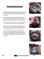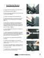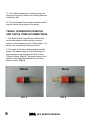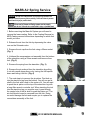
1
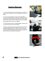
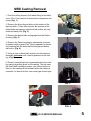
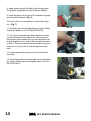
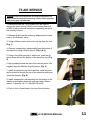
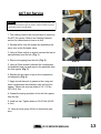
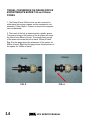
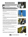
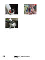
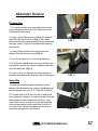
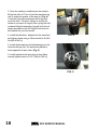
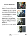
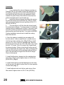
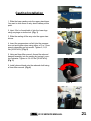
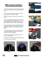
INTRODUCTION
This manual is intended to guide the user through basic service of Manitou front forks. Service is
supported by the identification of common parts and assemblies that have been assembled into
Service Kits. The purpose of this manual will be to describe conditions that may drive the need
for service and to provide installation instructions for the kits.
Due to the time-consuming nature of suspension fork service, at this time our primary focus is to
offer service kits that minimize the amount of downtime and labor involved.
Important information is highlighted in this manual by the following notations:
WARNING
Failure to follow WARNING instructions could result in severe injury or death to the
person inspecting or repairing the suspension fork or the user.
CAUTION
A CAUTION a caution indicates special precautions that must be taken to avoid damage to
the product.
NOTE
A NOTE provides key information to make procedures easier or clearer
GENERAL WARNING: Suspension forks by design can contain preloaded springs, gases
and fluids under extreme pressure and warnings contained in this manual must be
observed to reduce the possibility of injury or possible death. Following these
instructions can help you reduce the risk of being injured. Any questions in regards to the
information in this manual should be directed to Manitou Customer Service at (888) 6863472.
WARNING: Suspension forks uses preloaded spring(s) to provide compression spring
resistance. This system must be relieved of preload prior to servicing. Failure to relieve
air pressure could result in injury or possible death.
CAUTION: Suspension forks use precision machined aluminum and other soft alloy components.
Using correct tools for assembly is essential to prevent damage.
2012 SERVICE MANUAL
This manual is divided up into different sections, each one pertaining to a different part of the
servicing of your fork. Below is a list of our fork models and which sections you will use to service
your particular fork.
Circus Comp/Match/Tower Comp Forks
1.
Section 1 – Casting Removal
2.
Section 3 – Dust Seal Replacement
3.
Section 4 – Coil Spring Service
4.
Section 8 – Absolute+ Service
5.
Section 10 – Casting Installation
Minute Pro/Tower Pro Forks
1.
Section 1 – Casting Removal
2.
Section 3 – Dust Seal Replacement
3.
Section 5 – MARS Air Spring Service
4.
Section 8 - Absolute+ Service
5.
Section 10 – Casting Installation
Circus Expert/Minute Expert/Tower Expert
Forks
1.
Section 1 – Casting Removal
2.
Section 3 – Dust Seal Replacement
3.
Section 7 – ACT Air Service
4.
Section 8 – Absolute+ Service
5.
Section 10 – Casting Installation
R7 Forks
1.
Section 1 – Casting Removal
2.
Section 3 – Dust Seal Replacement
3.
Section 6 – TS Air Service
4.
Section 8 – Absolute+ Service
5.
Section 10 - Casting Installation
R7 MRD Forks
1.
Section 2 – MRD Casting Removal
2.
Section 3 – Dust Seal Replacement
3.
Section 6 – TS Air Service
4.
Section 9 – Absolute+ MRD Service
5.
Section 11 – MRD Casting Installation
Marvel Expert Forks
1.
Section 1 – Casting Removal
2.
Section 3 – Dust Seal Replacement
3.
Section 8 – ISO Air Service
4.
Section 8 – Absolute+ Service
5.
Section 10 – Casting Installation
Marvel Pro Forks
1.
Section 2 – MRD Casting Removal
2.
Section 3 – Dust Seal Replacement
3.
Section 8 – ISO Air Service
4.
Section 9 – Absolute+ MRD Service
5.
Section 11 – MRD Casting Installation
2012 SERVICE MANUAL
Table of Contents
Section
Page Number
Section 1 - Casting Removal
Section 2 - MRD Casting Removal
Section 3 - Dust Seal Replacement
Section 4 - Coil Spring Service
Section 5 - MARS Air Spring Service
Section 6 - TS Air Spring Service
Section 7 - ACT Air Spring Service
Section 8 - ISO Air Spring Service
Section 9 - Absolute+ Service
Section 10 - Absolute+ MRD Service
Section 11 - Casting Installation
Section 12 - MRD Casting Installation
Oil Height Chart
Fork Exploded Diagrams
4
5
6
7-8
9 - 10
11 - 12
13 - 14
15 - 16
17 - 18
19 - 20
21
22
23
24 - 34
Contact Information
Hayes Bicycle Group
6750 W Florist Ave
Milwaukee, WI 53218
Toll Free:
Direct:
FAX:
E-mail:
Web site:
(888) 686-3472
(262) 242-4300
(414) 462-0214
[email protected]
www.manitoumtb.com
2012 SERVICE MANUAL
Casting Removal
1. From the left leg dropout (Left when sitting on the bike), use
a 10 or 11mm wrench to remove the compression rod screw.
(Fig. 1)
2. From the right leg dropout, if the fork has adjustable rebound, the knob will need to be removed. Screw the rebound
all the way in (clockwise) remove the 2mm hex screw inside
the knob by turning it counter clockwise. Remove the knob by
pulling gently away from the fork. (Fig. 2)
FIG. 1
3. Use an 8mm hex wrench to turn the damper clockwise until
it can be pushed into the casting. (Fig. 3)
4. Remove crown/steer/inner leg assembly from the outer leg
casting by pulling firmly on the casting. If the fork uses the
Semi bath Lubrication system, use caution as the oil that is in
the casting will be released when the casting is removed, it is
best to do this over some type of catch pan.
FIG. 2
FIG. 3
2012 SERVICE MANUAL
MRD Casting Removal
1. From the left leg dropout (Left when sitting on the bike),
use a 10 or 11mm wrench to remove the compression rod
screw. (Fig. 1)
2. Remove the blue rebound knob on the bottom of the
right leg with a 1.5mm Allen wrench. Be cautious of the
detent balls and springs under the knob as they are very
small and easily lost. (Fig. 2)
3. Remove the detent balls and springs from the Detent
Housing. (Fig. 3)
FIG. 1
4. Remove the Detent housing by unscrewing it counterclockwise using a green Park Tool pin spanner (or similar
tool) inserted into the holes that the springs and detent
balls sit in. (Fig. 4)
5. Using a 7mm or 8mm Allen wrench, turn the rebound
assembly clockwise until it can be pushed into the casting. (Fig. 5)
FIG. 2
6. Remove crown/steer/inner leg assembly from the outer
leg casting by pulling firmly on the casting. The fork uses
the Semi bath Lubrication system, use caution as the oil
that is in the casting will be released when the casting is
removed, it is best to do this over some type of catch pan.
FIG. 3
FIG. 5
2012 SERVICE MANUAL
FIG. 4
Dust Seal Replacement
1. Before replacing the dust seals you will need to remove
the lower casting. Refer to the Casting Removal or MRD
Casting Removal instructions depending on which model
fork you have.
FIG. 1
2. To remove the dust seals, first remove the seal tension
springs (otherwise they will get damaged), then take a
large flat-bladed screwdriver and insert the tip between the
bottom of the seal and the top of the foam wiper. (Fig. 1)
3. Push down on the screwdriver. This will pop the seal out
of the casting. Next remove the foam oil ring. (Fig. 2)
4. Oil the foam rings (new or after cleaning the old rings)
with a small amount of semi-bath oil and place them in the
top of the casting above the Upper Bushings. (Fig. 3)
FIG. 2
5. Install the dust seal into the leg, use a large socket or
piece of round tubing that is large enough in diameter to
press on the outside shoulder of the seal rather than putting pressure on the sealing lip and spring so that they are
not damaged. (Fig. 4) Repeat steps 1-4 for the opposite
casting leg.
FIG. 3
2012 SERVICE MANUAL
FIG. 4
Coil Spring Service
1. Using a 2mm Allen wrench, remove the knob
from the preload adjuster. (Fig. 1)
2. Remove the preload adjuster from the fork using
a 20mm socket. (Fig. 2)
FIG 1
3. Pull the coil spring out of the stanchion leg.
4. Remove travel spacer and bottom out bumper
from the end of the compression rod assembly.
(Fig. 3)
5. Remove the compression rod assembly from
the stanchion leg. The compression rod comes
out from the top of the stanchion leg. Turn the fork
sideways or upside down to get the compression
rod out of the leg. (Fig. 4)
FIG 2
6. Inspect compression rod and top-out bumper. If
damaged replace.
7. Install compression rod assembly into the stanchion leg. Insert through the top of the stanchion
leg and maneuver the rod until it drops through the
hole at the bottom of the stanchion leg.
8. Lightly grease the spring and install into stanchion leg.
FIG 3
9. Install the preload adjuster into the fork leg.
Tighten down using a 20mm socket to 5,1- 6,2 Nm
(45-55 in. lbs).
10. Using a 2mm Allen wrench, install the preload
knob onto the adjuster. Tighten knob down to 0,50,7 Nm (4-6 in. lbs).
11. Install bottom-out bumper and travel spacer
onto the end of the compression rod.
2012 SERVICE MANUAL
FIG 4
12. The casting needs to be removed prior to servicing the coil spring. Refer to the Casting Removal
Instructions first.
13. Turn the preload knob counter-clockwise until it
stops to relieve the preload on the spring.
TRAVEL CONVERSION ON MATCH
AND CIRCUS COMP 80/100MM FORKS
1. The Match/Circus Comp 80 and 100mm forks
can be converted to either travel by moving a
spacer on the compression rod. Follow steps 1-7 to
remove the compression rod form the fork.
2. The travel of the fork is determined by a plastic
spacer. The spacer being on top of the flange on
the compression rod will cause the fork to have
100mm of travel. (Fig. 5). The spacer being on the
bottom on the flange will cause the fork to have
80mm of travel. (Fig. 6)
100mm
FIG. 5
80mm
FIG. 6
2012 SERVICE MANUAL
MARS Air Spring Service
WARNING This fork uses compressed air to provide spring resistance and
must be relieved of pressure prior to servicing. Failure to relieve air pressure
could result in injury or possible death.
FIG. 1
1. Before servicing the Mars Air System you will need to
remove the lower casting. Refer to the Casting Removal or
MRD Casting removal instructions depending on which fork
model you have.
2. Release the air from the fork by depressing the valve
core on the Schrader valve.
3. Remove the air cap from the fork using a 20mm socket.
(Fig. 1)
4. Unthread the compression rod assembly from the bottom
of the stanchion using a 22mm wrench and remove from
fork. (Fig. 2)
FIG. 2
5. Remove the spring from the stanchion. (Fig. 3)
6. Remove the air pushrod from the stanchion by pulling
it out with needle nose pliers or by turning the fork upside
down and letting it fall out. (Fig. 4)
7. The next step is to remove the air piston. First look up
into the stanchion leg from the bottom. You will see an air
shelf in the fork with a hole in the center of it. You will want
to push the air piston out the top of the stanchion leg with
a long Allen wrench or similar tool. When inserting the tool
into the stanchion leg you must be sure it goes through
the center hole of the air shelf to push the piston out. The
air shelf should never be removed from the fork. Doing
so would damage the fork and require you to replace the
crown/steer assembly of the fork.
FIG. 3
FIG. 4
2012 SERVICE MANUAL
8. Apply grease around the side of the new air piston.
We suggest using Manitou Prep M grease. (Fig. 5)
9. Install air piston into the top of the stanchion leg and
push it past the threads. (Fig. 6)
10. Pour in 5cc’s of semi-bath oil on top of the air piston. (Fig. 7)
11. Install air cap onto the stanchion leg using a 20mm
socket and tighten to 6,8-8,0 Nm [60-80 lbf*in]
FIG. 5
12. Turn the fork upside down and insert the air pushrod into the bottom of the stanchion. The long end of
the pushrod goes towards the top of the fork and must
drop through the center hole of the air shelf discussed
in Step 7. Drop the pushrod into the stanchion leg and
maneuver it until you feel it drop through the center
hole.
13. Lightly grease the spring and insert into the stanchion leg.
FIG. 6
14. Install compression rod assembly into the stanchion
leg using a 22mm wrench and tighten down to 6,8-8,0
Nm [60-80 lbf*in]
FIG. 7
10
2012 SERVICE MANUAL
TS AIR SERVICE
WARNING This fork uses compressed air to provide spring resistance and
must be relieved of pressure prior to servicing. Failure to relieve air pressure
could result in injury or possible death.
1. Before servicing the TS Air system you will need to
remove the lower casting. Refer to the Casting Removal
or MRD Casting removal instructions depending on which
fork model you have.
FIG. 1
2. Release all air from the system by depressing the valve
core on the Schrader valve.
3. Using a 20mm socket, remove the air cap from the fork.
(Fig. 1)
4. Remove compression rod assembly from the bottom of
the stanchion using a 22mm wrench. (Fig. 2 & 3)
5. Using a long Allen wrench or similar tool, push the air
piston down and out the bottom of the stanchion leg. (Fig.
4)
FIG. 2
6. Apply grease around the side of the new air piston. We
suggest using the Manitou Prep M grease. (Fig. 5)
7. Install air piston into the fork stanchion. Install by pushing the piston in through the top of the stanchion and push
it past the threads. (Fig. 6)
8. Install compression rod assembly into the bottom of the
stanchion and tighten down the end cap using a 22mm
wrench. Tighten to 9,0–11,3 Nm [80-100 lbf*in]
FIG. 3
9. Pour in 5cc’s of semi-bath oil on top of the air piston.
FIG. 4
2012 SERVICE MANUAL
11
FIG. 5
12
FIG. 6
2012 SERVICE MANUAL
ACT Air Service
WARNING This fork uses compressed air to provide spring resistance and
must be relieved of pressure prior to servicing. Failure to relieve air pressure
could result in injury or possible death.
1. The casting needs to be removed prior to servicing
the ACT Air system. Refer to the Casting Removal
section for instructions on how to do this.
FIG. 1
2. Release all air from the system by depressing the
valve core on the Schrader valve.
3. Using a 20mm socket or wrench remove the top air
cap assembly from the fork. (Fig. 1)
4. Remove the spring from the fork. (Fig. 2)
FIG. 2
5. Using a 22mm wrench unthread the compression
rod assembly end cap and remove the assembly from
the fork uppers. (Fig. 3)
6. Replace the air piston o-ring on the compression
rod assembly. (Fig. 4)
7. Apply a small amount of grease to the o-ring and
insert compression rod assembly back into the fork
uppers. Tighten the end cap down to 9.0-11.3 Nm
(80-100 in. lbs)
FIG. 3
8. Grease the spring and place it into the fork uppers
from the top.
9. Install air cap. Tighten down to 6.8-9.0 Nm (60-80
in. lbs)
10. Using a shock pump, fill fork to desired air pressure.
FIG. 4
2012 SERVICE MANUAL
13
TRAVEL CONVERSION ON DRAKE/CIRCUS
EXPERT/MINUTE EXPERT 80 and 100mm
FORKS
1. The Drake 80 and 100mm forks can be converted to
either travel by moving a spacer on the compression rod
assembly. Follow Steps 1-5 above to remove the compression rod assembly.
2. The travel of the fork is determined by a plastic spacer.
The spacer being on the bottom of the air piston will cause
the fork to have 80mm of travel. The spacer being on top
of the piston will cause the fork to have 100mm of travel.
Fig. 5 on this page shows the placement of the spacer for
80mm of travel. Fig. 6 on this page shows the placement of
the spacer for 100mm of travel.
100mm
80mm
FIG. 5
14
FIG. 6
2012 SERVICE MANUAL
ISO Air Spring Service
WARNING This fork uses compressed air to provide spring resistance and
must be relieved of pressure prior to servicing. Failure to relieve air pressure
could result in injury or possible death.
FIG. 1
1.Before servicing the Mars Air System you will need to
remove the lower casting. Refer to the Casting Removal or
MRD Casting removal instructions depending on which fork
model you have.
2. Release the air from the fork by depressing the valve
core on the Schrader valve.
3. Remove the air cap from the fork using a 20mm socket.
(Fig. 1)
4. Unthread the compression rod assembly from the bottom
of the stanchion using a 22mm wrench and remove from
fork. (Fig. 2 &3)
5. Remove the air piston from the stanchion leg. There are
two ways to do this. You can use a long Allen wrench or
dowel rod to push the air piston through and out the bottom
of the stanchion leg. (Fig. 4) You can alternatively use a
6mm bolt and thread it into the center of the piston and pull
it out the top of the fork leg. (Fig. 5) The second method is
convenient when you are just servicing the air piston and
do not want to disassemble the fork.
FIG. 2
FIG. 3
6. Apply grease around the side of the new air piston. We
suggest using Manitou Prep M grease. (Fig. 6)
7. Install air piston into the top of the stanchion leg and
push it past the threads.
8. Pour in 5cc’s of semi-bath oil on top of the air piston.
(Fig. 7)
9. Install air cap onto the stanchion leg using a 20mm
socket and tighten to 6,8-8,0 Nm [60-80 lbf*in]
2012 SERVICE MANUAL
FIG. 4
15
FIG. 5
FIG. 6
FIG. 7
16
2012 SERVICE MANUAL
Absolute+ Service
Disassembly
1. The casting needs to be removed prior to servicing the damping side of the fork. Refer to the Casting Removal instructions.
2. Using a 2mm Allen wrench, remove the adjuster
knob from the top of the fork. (Fig. 1) Be careful
when removing the knob as there are two detent ball
bearings under it. Remove the detent ball bearings
and springs.
FIG. 1
3. Using a 24mm socket remove the Absolute+
damper from the stanchion leg. (Fig. 2)
4. Pour the damping oil out of the stanchion leg.
5. Turn the fork upside down and using a 22mm box
end wrench, remove the rebound damper assembly
from the stanchion. (Fig. 3)
6. Check o-rings on rebound and compression assemblies and replace any that are worn or damaged.
FIG. 2
Assembly
1. Install the rebound damper assembly into the
bottom of the stanchion leg. Using a 22mm box end
wrench tighten down to 9,0-11,3 Nm [80-100 lbf*in].
2. The next step is to fill the fork with oil and install
the compression damper. To ensure proper oil height
the casting must be installed prior to filling. If you
have other service to perform on the fork continue
onto the appropriate section and finish that first. If
not refer to the Casting Installation instructions to
install the casting back onto the fork.
2012 SERVICE MANUAL
FIG. 3
17
3. Once the casting is installed you are ready to
fill the fork with oil. Pour oil into the stanchion leg
until it is about a quarter of the way up. (Fig. 4)
Cover the hole in the stanchion with a rag and
cycle the fork 7-10 times. Failure to do this will
cause an incorrect oil height. After cycling the fork,
continue filling the stanchion leg with oil to the oil
height specified on the Oil Height Chart found in
this manual for your fork model.
4. Install the Absolute+ damper into the stanchion
and tighten down using a 24mm socket to 6,8-9,0
Nm [60-80 lbf*in].
FIG. 4
5. Install detent springs and ball bearings into the
holes on the top cap. You want them placed in
holes opposite of each other. (Fig. 5)
6. Install adjuster knob and using a 2mm Allen
wrench tighten down to 0,5-0,7 Nm [4-6 lbf*in].
FIG. 5
18
2012 SERVICE MANUAL
Absolute+ MRD Service
Disassembly
1. The casting will need to be removed prior to servicing
the damping side of the fork. Refer to the MRD Casting
Removal Instructions.
FIG. 1
2. Using a 2mm Allen wrench, remove the adjuster knob
from the top of the fork leg. (Fig. 1) Be careful when
removing the knob as there are two detent ball bearings
below the knob. Remove the detent springs from the top
cap.
3.Remove the Absolute+ damper from the stanchion leg
using a 24mm socket. (Fig. 2)
4. Pour the damping oil out of the fork leg.
FIG. 2
5. Turn the fork upside down and using a 15mm open
end wrench, unthread the rebound damping assembly
from the bottom of the stanchion. (Fig. 3) The rebound
assembly will come out of the fork leg with the cartridge
tube attached to it. (Fig. 4) If you are replacing the tube
or the damper, pull the cartridge tube off the damper end
cap. The tube is tightly fit into the damper cap so it can
be difficult to get off.
6. Check o-rings on rebound damper end cap and ABS+
compression damper top cap and replace if damaged or
worn.
FIG. 3
FIG. 4
2012 SERVICE MANUAL
19
Assembly
1.
If you replaced the rebound damper cartridge or
cartridge tube you will need to press the tube back onto
the damper assembly end cap. First slide the damper
end cap all the way to the top of the assembly (top is
towards the piston head). Next slide the tube over the
piston head and press it into the end cap.
2.
Install the rebound damper/cartridge tube assembly into the bottom of the stanchion leg. Using a 15mm
open end wrench tighten the end cap down to 9,0-11,3
Nm [80-100 lbf*in].
3.
The next step is to fill the fork with oil and install
the compression damper. To ensure proper oil height the
casting must be installed prior to filling. If you have other
service to perform on the fork continue onto the appropriate section and finish that first. If not refer to the MRD
Casting Installation Instructions to install the casting
back onto the fork.
4. Once the casting is installed you are ready to fill
the fork with oil. Insert a small funnel or similar device
into the top of the cartridge tube. (Fig. 5) Pour a small
amount of oil (10cc’s) into the cartridge tube. Remove
the funnel and cover the top of the tube with a rag. Cycle
the fork 7-10 times. This is to ensure the oil gets under
the rebound piston. Failure to do this will cause your oil
level to drop below the proper level. After cycling the fork
insert the funnel back into the cartridge tube and fill the
fork to the specified oil height found on the Oil Height
Chart in this manual.
5. Install the Absolute+ damper into the cartridge tube
and using a 24mm socket tighten down to 6,8-9,0 Nm
[60-80 lbf*in]. (Fig. 6)
6. Install detent springs and ball bearings into the holes
on the top cap. You want to place them in holes opposite
of each other. (Fig. 7)
7. Install adjuster knob onto the hex and using a 2mm
Allen wrench tighten down to 0,5-0,7 Nm [4-6 lbf*in].
20
2012 SERVICE MANUAL
FIG. 5
FIG. 6
FIG. 7
Casting Installation
1. Slide the lower casting onto the upper stanchions.
You want to slide them on only about halfway at this
point.
2. Inject 16cc’s of semi-bath oil into the lower legs
using a syringe or similar tool. (Fig. 1)
FIG. 1
3. Slide the casting all the way onto the upper stanchions.
4. Insert the compression rod bolt into the compression rod and tighten down using either a 10 or 11mm
wrench depending on fork model. Tighten 5,1-6,2
Nm [45-55 lbf*in]. (Fig. 2)
5. Using an 8mm Allen wrench, thread the rebound
damper assembly into the casting by turning it counter-clockwise. Tighten to 3,4-4,5 Nm [30-40 lbf*in].
(Fig. 3)
FIG. 2
6. Install rebound knob onto the rebound shaft using
a 2mm Allen wrench. (Fig. 4)
FIG. 3
FIG. 4
2012 SERVICE MANUAL
21
MRD Casting Installation
1. Slide the lower casting onto the upper stanchions.
You want to slide them on only about halfway at this
point.
2. Inject 16cc’s of semi-bath oil into the lower legs
using a syringe or similar tool. (Fig. 1)
FIG. 1
3. Slide the casting all the way onto the upper stanchions.
4. Insert the compression rod bolt into the compression rod and tighten down using either a 10 or 11mm
wrench depending on fork model. Tighten to the
torque specified in the back of the manual. (Fig. 2)
5. Using an 8mm Allen wrench, thread the rebound
damper assembly into the casting by turning it counter-clockwise. Tighten to 3,4-4,5 Nm [30-40 lbf*in].
(Fig. 3)
FIG. 2
6. Thread the detent housing on the rebound damper assembly threads using a green Park Tool pin
spanner or similar tool. (Fig. 4)
7. Place springs and detent ball bearings into the
detent housing. (Fig. 5)
8. Install rebound knob onto the rebound shaft using
a 1.5mm Allen wrench. (Fig. 6)
FIG. 6
22
FIG. 5
2012 SERVICE MANUAL
FIG. 3
FIG. 4
OIL HEIGHT CHART
FORK
Circus Comp/Match
Match
Circus Expert/Minute
Expert
Circus Expert/ Minute
Expert
R7
R7
Minute Pro
Minute Pro
Minute Pro
Tower Expert
Tower Expert
Tower Expert
Tower Pro
Tower Pro
Tower Pro
R7 MRD
R7 MRD
Marvel Expert
Marvel Pro
Marvel Pro
TRAVEL
80/100mm
130mm
80/100mm
OIL HEIGHT
Nominal
83
83
87
(mm)
Range
80-85
80-85
85-90
130mm
87
85-90
80mm
100mm
100mm
120mm
140mm
80mm
100mm
120mm
80mm
100mm
120mm
80mm
100mm
80/100mm
100mm
120mm
83
83
87
87
87
87
87
87
87
87
87
103
108
87
108
113
80-85
80-85
85-90
85-90
85-90
85-90
85-90
85-90
85-90
85-90
85-90
100 -105
105 -110
85-90
105 -110
110 -115
2012 SERVICE MANUAL
23
24
2012 SERVICE MANUAL
E
E
E
141-23994-K025
141-23994-K026
141-27181-K007
85-5293
1. Outer Casting TA NB - Black
1. Outer Casting TA NB - White
2. Bushing Kit
3. Seal Kit
C
G
G
141-27181-K005
141-27220-K004
141-27181-K002
141-26686-K001
141-26686-K002
141-26686-K003
141-27181-K003
6. Crown/Steer/Leg 80/100 Steel
6. Crown/Steer/Leg 80/100 Blk
Crwn
6. Crown/Steer/Leg 80/100 Wht
Crwn
7. Preload Adjuster
8. Ride Kit – Soft – 80/100
8. Ride Kit – Medium – 80/100
8. Ride Kit – Firm – 80/100
9. Compression Rod
141-27220-K005
A
5. Absolute+ Damper
H
G
D
D
D
B
141-27220-K001
141-26532-K006
4. Rebound Damper Assembly
K
E
E
141-23994-K015
141-23994-K016
Kit Group
1. Outer Casting QR NB - White
Part Number
1. Outer Casting QR NB - Black
Part Description
Circus Comp Exploded View
2012 SERVICE MANUAL
25
1. Compression Rod 80/100
1. Compression Rod 130
2. Ride Kit – Soft – 80/100
2. Ride Kit – Medium – 80/100
2. Ride Kit – Firm – 80/100
2. Ride Kit – Soft - 130
2. Ride Kit – Medium - 130
2. Ride Kit – Firm - 130
3. Air Preload Cap
4. Crown/Steer/Leg 80/100 Blk
Crwn
4. Crown/Steer/Leg 80/100
Wht Crwn
4. Crown/Steer/Leg 130 Blk
Crwn
4. Crown/Steer/Leg 130 Wht
Crwn
5. Absolute+ Damper
6. Rebound Damper 80/100
6. Rebound Damper 130
7. Seal Kit
8. Bushing Kit
9. Outer Casting QR NB Black
9. Outer Casting QR NB White
9. Outer Casting TA NB Black
9. Outer Casting TA NB White
10. Knob Kit
Part Description
D
D
D
D
A
B
B
K
141-27220-K006
141-27220-K007
141-27220-K008
141-27220-K009
141-26532-K007
141-27220-K002
141-27220-K003
85-5293
141-27181-K007
141-23994-K015
141-23994-K016
141-23994-K025
141-23994-K026
141-27177-K001
E
E
E
E
E
I
G
G
G
G
G
G
C
Kit Group
H
H
141-23999-K003
141-23999-K003
141-23998-K001
141-23998-K004
141-23998-K007
141-23998-K003
141-23998-K006
141-23998-K009
141-23992-K002
Part Number
Circus Expert Fork Schematic
26
2012 SERVICE MANUAL
2
141-28131 -K 007
141-28131 -K 005
141-28131 -K 008
141-28131 -K 006
141-28131 -K 011
141-28131 -K 009
141-28131 -K 012
141-28131 -K 010
141-28131 -K 017
141-26532 -K 010
141-28131 -K 018
141-27988 -K 018
141-27988 -K 017
141-27988 -K 020
141-27988 -K 019
141-28131 -K 016
141-28131 -K 024
85-596 4
85-529 3
141-28131 -K 013
141-28131 -K 014
141-28131 -K 015
141-27988 -K 013
1. C row n/S teer/A ssem bly, 1 1/8 S teer, 100m m , B lk C rw n
1. C row n/S teer/A ssem bly, 1 1/8 S teer, 100m m , W ht C rw n
1. C row n/S teer/A ssem bly, 1 1/8 S teer, 120m m , B lk C rw n
1. C row n/S teer/A ssem bly, 1 1/8 S teer, 120m m , W ht C rw n
1. C row n/S teer/A ssem bly, T aper S teer, 100m m , B lk C rw n
1. C row n/S teer/A ssem bly, T aper S teer, 100m m , W ht C rw n
1. C row n/S teer/A ssem bly, T aper S teer, 120m m , B lk C rw n
1. C row n/S teer/A ssem bly, T aper S teer, 120m m , W ht C rw n
2. K nob K it
3. A bsolute+ D am per A ssem bly
4. R ebound D am per A ssem bly
5. O uter C asting, Q R N B , B lack
5. O uter C asting, Q R N B , W hite
5. O uter C asting, Q R 15 N B , B lack (Q R 15 axle included)
5. O uter C asting, Q R 15 N B , W hite (Q R 15 axle included)
6. Q R 15 A xle
7. Q R 15 A xle H ardw are (insert & endcap)
8. B ushing K it
9. S eal K it
10. C om pression R od A ssem bly, 100m m
10. C om pression R od A ssem bly, 120m m
11. A ir P iston
12. A ir C ap
6
P art N u m b er
P art D escrip tio n
5
D
D
D
D
D
D
D
D
I
A
B
E
E
E
E
E
E
E
K
H
H
G
C
7
K it G ro u p
4
Marvel Expert Fork Schematic
3
8
2
9
1
10
11
12
2012 SERVICE MANUAL
27
2
6
1 4 1 -2 8 1 3 1 -K 0 0 7
1 4 1 -2 8 1 3 1 -K 0 0 5
1 4 1 -2 8 1 3 1 -K 0 0 8
1 4 1 -2 8 1 3 1 -K 0 0 6
1 4 1 -2 8 1 3 1 -K 0 1 1
1 4 1 -2 8 1 3 1 -K 0 0 9
1 4 1 -2 8 1 3 1 -K 0 1 2
1 4 1 -2 8 1 3 1 -K 0 1 0
1 4 1 -2 8 1 3 1 -K 0 1 7
1 4 1 -2 6 5 3 2 -K 0 0 9
1 4 1 -2 8 1 3 1 -K 0 0 3
1 4 1 -2 8 1 3 1 -K 0 0 4
1 4 1 -2 8 1 3 1 -K 0 0 1
1 4 1 -2 8 1 3 1 -K 0 0 2
8 3 -3 2 8 3
1 4 1 -2 8 1 3 1 -K 0 1 6
1 4 1 -2 8 1 3 1 -K 0 2 4
1 4 1 -2 7 9 8 8 -K 0 1 8
1 4 1 -2 7 9 8 8 -K 0 1 7
1 4 1 -2 7 9 8 8 -K 0 2 0
1 4 1 -2 7 9 8 8 -K 0 1 9
8 5 -5 9 6 4
8 5 -5 2 9 3
1 4 1 -2 8 1 3 1 -K 0 1 3
1 4 1 -2 8 1 3 1 -K 0 1 4
1 4 1 -2 8 1 3 1 -K 0 1 5
1 4 1 -2 7 9 8 8 -K 0 1 3
1 . C ro w n /S te e r/A s s e m b ly , 1 1 /8 S te e r, 1 0 0 m m , B lk C rw n
1 . C ro w n /S te e r/A s s e m b ly , 1 1 /8 S te e r, 1 0 0 m m , W h t C rw n
1 . C ro w n /S te e r/A s s e m b ly , 1 1 /8 S te e r, 1 2 0 m m , B lk C rw n
1 . C ro w n /S te e r/A s s e m b ly , 1 1 /8 S te e r, 1 2 0 m m , W h t C rw n
1 . C ro w n /S te e r/A s s e m b ly , T a p e r S te e r, 1 0 0 m m , B lk C rw n
1 . C ro w n /S te e r/A s s e m b ly , T a p e r S te e r, 1 0 0 m m , W h t C rw n
1 . C ro w n /S te e r/A s s e m b ly , T a p e r S te e r, 1 2 0 m m , B lk C rw n
1 . C ro w n /S te e r/A s s e m b ly , T a p e r S te e r, 1 2 0 m m , W h t C rw n
2 . K n o b K it
3 . C a rtrid g e A b so lu te + D a m p e r A s s e m b ly
4 . C a rtrid g e T u b e , 1 1 /8 S te e r, 1 0 0 m m
4 . C a rtrid g e T u b e , 1 1 /8 S te e r, 1 2 0 m m
4 . C a rtrid g e T u b e , T a p e r S te e r, 1 0 0 m m
4 . C a rtrid g e T u b e , T a p e r S te e r, 1 2 0 m m
5 . C a rtrid g e R e b o u n d D a m p e r A s s e m b ly
6 . Q R 1 5 A xle
7 . Q R 1 5 A xle H a rd w a re (in s e rt & e n d ca p )
8 . O u te r C a s tin g , Q R N B , B la c k
8 . O u te r C a s tin g , Q R N B , W h ite
8 . O u te r C a s tin g , Q R 1 5 N B , B la c k (Q R 1 5 a xle in c lu d e d )
8 . O u te r C a s tin g , Q R 1 5 N B , W h ite (Q R 1 5 a xle in c lu d e d )
9 . B u sh in g K it
1 0 . S e a l K it
1 1 . C o m p re s s io n R o d A s s e m b ly, 1 0 0 m m
1 1 . C o m p re s s io n R o d A s s e m b ly, 1 2 0 m m
1 2 . A ir P is to n
1 3 . A ir C a p
5
P a rt N u m b e r
P a rt D e s c rip tio n
D
D
D
D
D
D
D
D
I
A
A
A
A
A
B
E
E
E
E
E
E
E
K
H
H
G
C
K it G ro u p
Marvel Pro Fork Schematic
7
4
8
3
9
10
2
1
11
12
13
28
2012 SERVICE MANUAL
G
H
H
141-26686-K004
141-26686-K005
141-26686-K006
141-27181-K003
141-27181-K004
8. Ride kit – Soft - 130
8. Ride Kit – Medium - 130
8. Ride Kit – Firm – 130
9. Compression Rod 80/100
9. Compression Rod 130
G
G
141-27181-K006
141-27181-K002
141-26686-K001
141-26686-K002
141-26686-K003
141-25404-K003
141-27181-K005
K
B
A
D
D
C
G
G
G
E
E
E
E
E
Kit Group
5. Absolute+ Damper
6. Crown/Steer/Leg 80/100
6. Crown/Steer/Leg 130
7. Preload Adjuster
8. Ride Kit – Soft – 80/100
8. Ride Kit – Medium – 80/100
8. Ride Kit – Firm – 80/100
3. Seal Kit
4. Rebound Damper Assembly
141-23994-K016
141-27181-K007
141-27177-K001
141-27181-K001
1. Outer Casting QR NB White
2. Bushing Kit
Part Number
141-23994-K005
141-23994-K006
141-23994-K015
Part Description
1. Outer Casting QR STD Black
1. Outer Casting QR STD White
1. Outer Casting QR NB Black
Match Exploded View
2012 SERVICE MANUAL
29
G
C
141-23998-K007
141-23998-K003
141-23998-K006
141-23998-K009
141-23992-K002
141-23993-K001
141-23993-K002
141-26532-K002
2. Ride Kit – Firm 80/100
2. Ride Kit – Soft 130
2. Ride Kit – Medium 130
2. Ride Kit - Firm 130
3. Air Preload Cap
4. Crown/Steer/Leg 80/100
4. Crown/Steer/Leg 130
5. Absolute+ Damper
G
2. Ride Kit – Medium 80/100
141-23994-K015
141-23994-K016
141-23994-K025
141-23994-K026
9. Outer Casting QR STD White
9. Outer Casting QR NB Black
9. Outer Casting QR NB White
9. Outer Casting TA Black
9. Outer Casting TA White
141-27177-K001
141-23994-K006
9. Outer Casting QR STD Black
10. Knob Kit
141-23994-K005
8. Bushing Kit
I
E
E
E
E
E
E
E
85-5964
7. Seal & Wiper Kit 32mm
B
K
141-23991-K003
85-5293
6. Rebound Damper
A
D
D
G
G
G
G
141-23998-K001
141-23998-K004
2. Ride Kit – Soft 80/ 100
1. Compression Rod Assembly
Kit Group
H
Part Number
141-23999-K003
Part Description
Minute Expert Fork Schematic
30
2012 SERVICE MANUAL
G
83-3171
83-3172
83-3173
2. Ride Kit – Soft 100
2. Ride Kit – Medium 100
2. Ride Kit – Firm 100
2. Ride Kit – X Firm 100
G
83-3177
2. Ride Kit – Medium 120
2. Ride Kit – Firm 120
85-5293
85-5964
141-23994-K015
141-23994-K016
141-23994-K025
141-23994-K026
141-27177-K001
9. Bushing Kit
10. Outer Casting QR – Black
10. Outer Casting QR – White
10. Outer Casting TA – Black
10. Outer Casting TA – White
11. Knob Kit
83-3156
5. Crown/Steer/Leg -120
8. Seal/Wiper Kit 32mm
83-3155
5. Crown/Steer/Leg -100
83-3341
83-3150
4. Air Cap
7. Rebound Damper
83-3188
3. Air Piston
83-3157
141-25683-K004
2. Ride Kit – X Firm 140
141-26532-K008
141-25683-K003
2. Ride Kit – Firm 140
6. Absolute+ Damper
C
141-25683-K002
2. Ride Kit – Medium 140
5. Crown/Steer/Leg -140
G
141-25683-K001
2. Ride Kit – Soft 140
E
E
E
E
E
E
K
B
A
D
D
D
G
G
G
G
G
141-26745
2. Ride Kit – X Firm 120
G
G
83-3175
83-3176
2. Ride Kit – Soft 120
G
G
H
G
83-3170
1. Compression Rod
Kit Group
Part Number
83-3183
Part Description
Minute Pro Fork Schematic
2012 SERVICE MANUAL
31
C
D
D
A
A
A
83-2669
83-2654
141-25389-K001
141-25389-K002
141-26532-K004
83-3270
1. Compression Rod Assembly – 100mm
2. Air Piston
3. Air Cap
4. Crown/Steer/Leg – 80mm
4. Crown/Steer/Leg – 100mm
5. Absolute+ Cartridge Damper
6. Cartridge Tube – 80mm
K
E
E
E
85-5321
85-5281
98-23561
98-23562
141-27200-K001
141-27200-K002
141-27177-K002
8. Bushing Kit
9. Seal Kit
10. Outer casting QR STD - Black
10. Outer Casting QR STD White
10. Outer Casting QR NB - Black
10. Outer Casting QR NB - White
11. Knob Kit
I
E
E
A
83-3271
83-3267
6. Cartridge Tube – 100mm
7. Cartridge Rebound Damper
G
H
H
83-3263
1. Compression Rod Assembly – 80mm
Kit Group
Part Number
83-3262
Part Description
R7 MRD Schematic
32
2012 SERVICE MANUAL
C
D
D
A
B
83-2669
83-2654
83-2656
83-2659
141-26532-K001
83-3254
1. Compression Rod Assembly – 100mm
2. Air Piston
3. Air Cap
4. Crown/Steer/Leg – 80mm
4. Crown/Steer/Leg – 100mm
5. Absolute+ Damper
6. Rebound Damper Assembly
E
I
98-23561
98-23562
141-27200-K001
141-27200-K002
141-27177-K003
9. Outer casting QR STD - Black
9. Outer Casting QR STD White
9. Outer Casting QR NB - Black
9. Outer Casting QR NB - White
10. Knob Kit
E
E
E
K
E
85-5281
85-5321
7. Seal Kit
8. Bushing Kit
G
H
H
83-3263
1. Compression Rod Assembly – 80mm
Kit Group
Part Number
83-3262
Part Description
R7 Pro Fork Schematic
2012 SERVICE MANUAL
33
141-23992-K002
141-23993-K004
141-23993-K005
141-26532-K002
3. Air Preload Cap
4. Crown/Steer/Leg 80/100
4. Crown/Steer/Leg 120
5. Absolute+ Damper
141-23994-K031
83-3303
141-23994-K036
141-27177-K001
9. Outer Casting QR NB White
9. Outer Casting TA Black
9. Outer Casting TA – White
10. Knob Kit
83-3302
141-23998-K008
2. Ride Kit - Firm 120
85-5964
141-23998-K006
2. Ride Kit – Medium 120
9. Outer Casting QR NB Black
141-23998-K002
2. Ride Kit – Soft 120
8. Bushing Kit
141-23998-K007
2. Ride Kit – Firm 80/100
141-23991-K004
141-23998-K004
2. Ride Kit – Medium 80/100
85-5293
141-23998-K001
7. Seal & Wiper Kit 32mm
141-23999-K004
1. Compression Rod - Air
2. Ride Kit – Soft 80/ 100
6. Rebound Damper
Part Number
Part Description
I
E
E
E
E
E
K
B
A
D
D
C
G
G
G
G
G
G
H
Kit Group
Tower Expert Fork Schematic
34
2012 SERVICE MANUAL
G
141-27177-K001
11. Knob Kit
E
141-23994-K031
10. Outer Casting QR – White
83-3303
83-3302
10. Outer Casting QR – Black
141-23994-K036
85-5964
9. Bushing Kit
10. Outer Casting TA – White
E
85-5293
8. Seal/Wiper Kit 32mm
10. Outer Casting TA – Black
A
83-3295
7. Rebound Damper Assembly
E
E
E
E
K
B
D
83-3331
141-26532-K008
D
D
83-3330
5. Crown/Steer/Leg - 100
6. Absolute+ Damper
C
83-3299
5. Crown/Steer/Leg - 80
5. Crown/Steer/Leg - 120
G
83-3150
4. Air Cap
G
141-26744-K003
2. Ride Kit – Firm – 120
141-25698
141-26744-K002
2. Ride Kit – Medium – 120
G
G
3. Air Piston
141-26744-K001
2. Ride Kit – X Firm – 100
G
G
G
G
G
G
H
Kit Group
2. Ride Kit – X Firm - 120
141-26743-K002
141-26743-K003
2. Ride Kit – Firm – 100
141-25690-K005
141-25690-K004
2. Ride Kit – Medium - 80
2. Ride Kit – Firm - 80
141-26743-K001
141-25690-K003
2. Ride Kit – Soft - 80
2. Ride Kit – Medium – 100
141-25690-K002
1. Compression Rod
2. Ride Kit – X Firm 80
Part Number
83-3312
Part Description
Tower Pro Fork Schematic