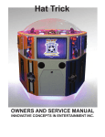
1
Triple Play
OWNERS AND SERVICE MANUAL
INNOVATIVE CONCEPTS IN ENTERTAINMENT INC.
10123 MAIN STREET, CLARENCE, NY 14031
SERVICE: 1-716-759-0360
FAX: 1-716-759-0884
E-MAIL: [email protected]
WEBSITE: www.icegame.com
1
2
TABLE OF CONTENTS
Safety and Warnings
4
Game Settings and Adjustments
5-6
Error Codes
6
Coin setup
7
Card Swipe Install
8-9
Assembly Drawings
10 - 27
Wiring Diagrams and Board Layout
28 - 31
Spare List
32
Warranty
33
Rev E - 1/27/2010 Triple Play - Card swipe ready
3
SAFETY AND WARNINGS
BEFORE YOU BEGIN
WARNING: WHEN INSTALLING THIS GAME, A GROUNDED A.C. RECEPTACLE MUST BE USED. FAILURE
TO DO SO COULD RESULT IN INJURY TO YOURSELF OR OTHERS. FAILURE TO USE A GROUNDED RECEPTACLE COULD ALSO CAUSE IMPROPER GAME OPERATION, OR DAMAGE TO THE ELECTRONICS.
DO NOT DEFEAT OR REMOVE THE GROUNDING PRONG ON THE POWER CORD FOR THE SAME REASON AS GIVEN ABOVE. USING AN IMPROPERLY GROUNDED GAME COULD VOID YOUR WARRANTY.
HAVE A QUALIFIED ELECTRICIAN CHECK YOUR A.C. RECEPTACLE TO BE SURE THE GROUND IS FUNCTIONING PROPERLY. DO NOT WASH YOUR GAME WITH A PRESSURE WASHER.
AVERTISSEMENT: lors de l'installation de ce jeu, la terre AC récipient doit être utilisé. Ne pas le faire pourrait entraîner un préjudice à vous ou à d'autres. Le non-recours à la terre récipient pourrait également causer une mauvaise opération de jeu, ou les dommages causés à l'électronique. NE PAS détériorer ou de retirer la broche de
terre sur le cordon d'alimentation pour la même raison, comme indiqué ci-dessus. Indûment l'aide d'un jeu de la
terre pourrait annuler votre garantie. Ont un électricien qualifié de vérifier votre récipient AC pour s'assurer que le
sol fonctionne correctement. Ne lavez pas votre jeu avec une laveuse à pression.
INSTALLATION
The game comes ready to play with just a few simple things to keep in mind.
1. Plug the game into the A.C. outlet and turn on power to the game through the inside of the game next to
the main board assembly. See assembly drawings for location.
THIS GAME IS DESIGNED TO DISSIPATE STATIC ELECTRICITY THROUGH THE GROUNDING PLANE OF THE
GAME. IF THE A.C. GROUND DOES NOT WORK, THE GAME COULD DISCHARGE STATIC ELECTRICITY
THROUGH THE GAME CIRCUITRY, WHICH COULD CAUSE DAMAGE.
2. Make sure the game is level after installation. It is necessary to make sure the game is level for safety
concerns.
3. Check that the A.C. voltage rating on the back of the game matches the A.C. voltage of your location.
THE POWER SUPPLY IS NOT VOLTAGE ADJUSTABLE. TO OPERATE THE GAME AT VOLTAGES OTHER THAN
THOSE IT WAS DESIGNED FOR. PLEASE CONTACT OUR SERVICE DEPARTMENT FOR VOLTAGE CONVERSION INFORMATION.
WARNING
DO NOT remove any of the components on the main board (e.g. compact flash and eproms) while
the game is powered on. This may cause permanent damage to the parts and the main board. Removing any main board component part while powered on will void the warranty.
Ne retirez pas l'un des composants sur la carte principale (par exemple Compact Flash et
EPROMs), tandis que le jeu est sous tension. Cette mai causer des dommages permanents aux
parties et la carte principale. Suppression de tout bord principal élément sous tension alors que annulera la garantie.
NOTE: THIS GAME IS INTENDED FOR INDOOR USE ONLY.
SHOCK HAZARD - DO NOT OPEN. REFER SERVICING TO SERVICE PERSONNEL.
REMARQUE: CE JEU EST DESTINÉ POUR USAGE À L'INTÉRIEUR SEULEMENT.
AVERTISSEMENT: RISQUE DE CHOC - NE PAS OUVRIR. RÉPARATION À UN PERSONNEL
DE SERVICE.
4
Game Settings and Adjustments
Your game has been shipped with our recommended defaults for optimal earnings. We have included extra
decals located in your parts package in case you would like to alter the game settings for your location. To
clear audit data press and hold the “UP” button located on the test panel and turn the AC power switch on.
The display will display a random pattern until you release the “Up” button. The game will then clear its audits and reset back in game mode. To reset your game back to factory default settings, press and hold “reset”
button located on the test panel and turn the AC power on. The display will display a random pattern until
you release the “reset” button. The game will revert to default settings and reset back to game mode.
At anytime you can press the “MODE” button located on the test panel to enter programming. Each time you
press the “MODE” button, you advance to the next option. Each option can be changed by either pressing the
“UP” or “DOWN” button also located on the test panel. The game will automatically save the change when
you press the mode button to advance to the next option.
Option
1
2
3
4
5
6
7
8
9
10
11
12
13
14
15
16
17
Description
Values
Hit Score
2 to 50
Hit Score
2 to 50
Hit Score
2 to 50
Hit Score
2 to 50
Hit Score
2 to 50
Jackpot Score
50 to 400 (increments of 50)
Wheel Speed control
400 to 900 (increments of 20)
Demo Sound
0 or 1
0=all the time
1=each time the coin is inserted
Display total ticket payout - See Audits below
Display total number of coins - See Audits below
Mercy Ticket in Out Hole
0 to 10
Locked value of Jackpot score 50 to 1000 (increments of 50)
Mercy Ticket for Coin in
0 to 5
LED Stadium Lights - See diagnostics below
Limit Switch Tests - See diagnostics below
Number of coins outputted by hopper per card swipe. 0 to 50
Return to game mode, press “reset” located on main pcb.
Default
15
5
30
10
20
150
SEE NOTE AT END
1
1
1000
0
10
**** NOTE ON OPTION 7 ****
Ensure that the speed is set so that one full revolution takes no more than 20 seconds. Speeds of more
than this will cause abnormal values to be paid or incorrect payouts.
Audits
Option 9 will display the total amount of tickets paid out. This option can be cleared as described above.
Option 10 will display the total amount of coins in. This option can be cleared as described above.
Test
Option 14 allows you to toggle the LED stadiums lights to ensure each LED is on. Pressing the “UP” button
will turn all LED on and pressing the “DOWN” button will turn them off.
5
Test (Continued)
Option 15 allows you to test the limit switches found in all the coin out holes. They are called “Home Run
Hole”, “Hit Hole”, and “Out Hole”. When a limit switch is defective, the display will show the hole with the
defective switch and the station number. The station numbers are 1 for red, 2 for blue, and 3 for yellow. A
display of “Ho” means home run hole, a display of “Ht” means Hit hole, and a display of “Ot” means out
hole. This error display can occur when game is first powered up if a switch is “stuck” on. The game will
not function until you enter programming and cycle through to option 16 or replace the defective switch.
Error Codes
At any time during game play, if a error occurs, the following will be displayed:
TICKET ERRORS:
After loading tickets, press the “Ticket Button” to dispense remaining tickets owed.
“Err1” appears on the Jackpot display. This means no ticket in ticket dispenser 1.
“Err2” appears on the Jackpot display. This means no ticket in ticket dispenser 2.
“Err3” appears on the Jackpot display. This means no ticket in ticket dispenser 3.
SENSOR ERRORS:
“ErrC” appears on the Jackpot display. This means the count sensor has failed.
“ErrZ” appears on the Jackpot display. This means the Home sensor has failed.
“ESSS” appears on the Jackpot Display. This means both sensors have failed.
A note on Sensor Failures:
The game expects a steady pulse from the count sensor and when the playfield has gone a full revolution a pulse is received by the home sensor. If after a period of time the home sensor is not seen, the game
will display the “ErrZ” error. Ensure that the home sensor flag triggers the top sensor when a full revolution
is done. If the playfield is not turning smoothly, this will cause the count sensor to become erratic and display a “ErrC” on the jackpot display. Check underneath the playfield to ensure that none of the brackets are
moving or have become loose. It might be necessary to remove one coin chute above the coin drawer to access the assembly. Please refer to the assembly diagrams for details. Total sensor failure will display a
“ESSS” meaning it cannot see both the count sensor or home sensor. Check to ensure there is no physical
damage to the sensor has occurred.
COIN SWITCH ERRORS:
When the game is powered on it will self check for stuck switches before entering game mode. If any
switch is found to be stuck, the game will display the error switch location code and will not enter game mode.
You can force the game into game mode by pressing mode button 16 times if it is not possible to repair at that
time. It is highly recommended to attended to this error as soon as possible.
“Ho1” appears on the jackpot display.
“Ho2” appears on the jackpot display.
“Ho3” appears on the jackpot display.
“Ht1” appears on the jackpot display.
“Ht2” appears on the jackpot display.
“Ht3” appears on the jackpot display.
“Ot1” appears on the jackpot display.
“Ot2” appears on the jackpot display.
“Ot3” appears on the jackpot display.
Defective switch located in the “Home run hole” on red station.
Defective switch located in the “Home run hole” on blue station.
Defective switch located in the “Home run hole” on yellow station.
Defective switch located in the “ Hit hole” on red station.
Defective switch located in the “Hit hole” on blue station.
Defective switch located in the “Hit hole” on yellow station.
Defective switch located in the “Out hole” on red station.
Defective switch located in the “Out hole” on blue station.
Defective switch located in the “Out hole” on yellow station.
6
SETUP - ASSEMBLY
This game has three stations that require you to insert your game room token or the
coin you wish to use into each of the coin comparators before they will accept any
coins or tokens. You will also need to load tickets into each station’s ticket dispenser.
See below for loading coins or tokens.
NOTE: RED STATION PICTURES SHOWN BELOW
STEP 1: At each station open the coin door to
access the coin comparator.
STEP 2: Pull back the coin holder and insert
your coin into the coin slot.
STEP 3: Release coin holder and close coin
door.
7
Card Swipe Installation
The game has been designed for easy integration of any card swipe system. You will find in the cash box all
the necessary hardware to install hoppers into each station. Hoppers and harnesses are not included and can
be obtained from ICE Service Department.
To convert your game to card swipe you will need to install a coin cup and hopper into each station.
Step 1:
Remove the four mounting screws to the front cover of the coin return chute found above each cash box.
Step 2:
Locate the bottom bracket plate and attach the mount for the hopper with four screws.
Step 3:
Slide the hopper and bracket assembly into the opening of the coin chute. You will need to slide the assembly back and then to the left to install the four mounting screws shown below.
8
Card Swipe Installation (Continued)
Step 4:
Locate the coin out ramp and position it in front where the coins are dispensed from the hopper and install the
two mounting screws.
Step 5:
Remove the coin chute plate from the door and install the coin cup with remaining hardware.
The remaining steps to finish your card swipe installation is different per card swipe system used. Refer to
your owners manual of your card swipe for further information.
The main logic board can directly control the hoppers. A wire harness from the hoppers to the main board
can be purchased form ICE Service Department. The default payout per swipe is 10 coins. This can be adjusted in the games settings. This game also has separate coin and ticket meters for each station located
above the main logic board. It is recommended to disconnect the meters and directly connect to your card
swipe system. Refer to the wiring diagrams from detail information.
9
Cabinet Assembly
14
14
13
13
77
88
99
22
66
10
10
12
12
15
15
11
11
11
33
55
14
4
Location
Part number
Description
QTY
1
Lower cabinet
1
2
Upper cabinet
1
3
Lower Bat assembly
6
4
Ticket door assembly
3
5
Main PCB door
1
6
Coin station assembly (Red, blue, yellow)
3
7
Jackpot display assembly (Red, blue, yellow)
3
8
Stadium light assembly
6
9
Coin collector platform assembly
3
Playfield base plate assembly
1
Center acryl playfield
1
10
See page 25
11
12
XHAT3027X
Right and left side window acryl set
6
13
XHAT3001
Acryl dome
1
Dome bracket
1
Title panel
3
14
15
XHAT7001TP
10
Cabinet Assembly (cont)
55
44
88
77
33
66
22
11
Location
Part number
Description
QTY
1
Main pcb assembly
1
2
Coin station assembly (Red/Blue/Yellow)
3
3
Jackpot display assembly (Red/Blue/Yellow)
3
4
Stadium light assembly (Red/Blue/Yellow)
6
5
Coin chute assembly (Red/Blue/Yellow)
3
6
Coin box cover (Red/Blue/Yellow)
3
7
Dome LED pcb bracket
3
Dome LED pcb
3
8
XHAT2037X
11
Cabinet Assembly (cont)
99
88
77
66
55
11
33
44
22
Location
Part number
Description
QTY
1
Main shaft assembly
1
2
Coin collector platform assembly
3
3
Bearing assembly
3
4
Middle cover plate bracket
6
5
Cabinet middle cover plate
3
Mirror acryl Set (two sizes per each set)
1
7
Playfield base plate assembly
1
8
Playfield base plate
1
9
Center acryl playfield
1
6
XHAT3025X
12
13
Bottom LED PCB bracket
Bottom finish plate
4
5
Bottom LED PCB
3
XHAT2038X
Coin Collection box assembly
2
Description
Motor assembly
Part number
1
Location
22
Cabinet Assembly (cont)
11
44
55
33
3
3
3
3
1
QTY
14
Bearing bracket 1
SEMS machine screw bolt
3
4
Bearing
Bearing bracket
XHAT1050
1
Description
33
11
2
Part number
Location
22
A
a
Bearing Bracket Assembly
2
1
1
1
QTY
Coin Chute Assembly
(1 each of red, blue and yellow for each station)
A
22
44
11
Bb
33
C
c
D
d
5
5
C
c
Location
Part number
Description
XHAT3002/3004/3004 (Red, Blue, Yellow)
Coin Chute Acryl (Red, Blue or Yellow stations)
1
2
Coin receiver (Red, Blue or Yellow stations)
2
3
Coin chute bracket (Red, Blue or Yellow stations)
1
4
Coin chute bracket 1 (Red, Blue, or Yellow stations)
1
5
Coin chute support (Red, Blue, or Yellow stations)
1
A
Truss screw bolt
2
B
Truss screw bolt
2
C
Truss screw bolt
2
D
Button head cap screw
1
E
U-lock nut
4
1
15
QTY
Jackpot Zone Coin Collector Assembly
11
22
33
A
a
bB
Location
Part number
Description
QTY
1
Jackpot coin collector
1
2
Jackpot coin collector
1
3
Jackpot switch and bracket assembly
2
4
SEMS machine screw bolt
2
5
SEMS machine screw bolt
4
16
Hit Zone Coin Collector Assembly
aA
11
22
3
B
b
Location
Part number
Description
QTY
1
Hit zone coin collector
1
2
Hit zone coin collector bracket
1
Limit switch assembly
2
4
SEMS machine screw bolt
2
5
SEMS machine screw bolt
4
3
XHAT211X
17
AA
11
22
11
33
A
A
Location
Part number
Description
QTY
1
Hit zone coin collector assembly
2
2
Jackpot coin collector assembly
1
3
Coin collector platform
1
4
SEMS machine screw bolt
6
18
Coin Station Assembly
(Red, Blue and Yellow)
B
b
3
3
11
2
2
A
a
Location
Part number
Description
QTY
1
Coin station box (Red, blue and yellow)
1
2
Coin machine
1
Coin station lock
1
A
Round rivet screw bolt
4
B
Lock nut
4
3
XHAT5014
19
22
Dd
1
1
Jackpot Display Assembly
C
c
Cc
Dd
5
5
4
Dd
4
3
3
a
A
7
7
66
8
8
Bb
Location
Part number
1
Description
QTY
Jackpot display case
1
2
See page 21
Coin LED pcb assembly
2
3
XHAT2033X
Jackpot FND pcb
1
4
XHAT2032X
Ticket FNC pcb
1
5
Title panel LED pcb
2
6
Jackpot display assembly
1
7
XHAT3006
Acryl pop
1
8
XHAT3007tp
Jackpot display cover
1
A
Truss screw bolt (black)
4
B
Truss screw bolt (silver)
6
C
U-lock nut
4
D
SEMS machine screw bolt
12
20
Coin LED pcb Assembly
(Available in Red, Blue, or Yellow - Two per color)
22
11
BOLT M3X8X2
Location Part number
1
Description
XHAT2039X/2040X/2041X Red, Blue, Yellow)
2
21
QTY
Coin LED pcb
6
Jackpot display LED pcb cover
6
Lower cabinet support - Bat assembly
a
a
22
11
Location
Part number
1
2
3
XHAT3005
Description
QTY
Lower cabinet support
1
Wooden bat
1
Screw bolt
7
22
Main Shaft Assembly
11
22
11
cC
3
44
3
55
66
aA
bB
Location
1
Part number
Description
XHAT1051
Bearing
2
Shaft
1
Bearing
2
Bearing housing
1
2
3
XHAT1052
4
QTY
5
XHAT1053
Shaft gear
1
6
XHAT1055
Lock Key
1
A
Washer
1
B
Socket head cap screw
1
C-Ring
1
C
XHAT1054
23
Motor Assembly
aa
dd
33
bb
bb
ee
22
11
66
cc
4
4
5
Location
Part number
Description
XHAT2008X
Motor with gearbox assembly
1
Motor bracket1
1
Motor gear
1
4
Motor bracket
1
5
Motor base plate
1
6
Motor assembly
1
Lock key
1
B
Socket head cap screw
2
C
SEMS machine screw bolt
1
D
Double SEMS SW+FW mode
4
E
SEMS machine screw bolt
4
1
2
3
A
XHAT1056
XHAT1057
24
QTY
Playfield base assembly
B
b
30
30 10
10
15
15
20
20
5
5
30
30
10
10
15
15 20
20 5
5
30
30
10
10 15
15
20
20
44
33
C
c
15 15
55
22
6
11
A
a
Location
Part number
Description
QTY
1
Playfield base plate
1
2
Playfield base plate
1
Acryl playfield set
1
4
Out zone board
15
5
Score label
15
6
Zero sensor bracket
1
A
Screws bolt
21
B
SEMS machine screw bolt
30
C
SEMS machine screw bolt
30
3
XHAT7002TPX
25
5
5
Stadium Light Supporter assembly
33
11
B
B
A
A
22
Location
Part number
1
Description
QTY
Stadium light support (red, blue, or yellow)
1
Stadium light PCB
1
3
Stadium light SUS cover
1
A
SEMS machine screw bolt
4
B
Flat Screw bolt (black)
4
2
XHAT2042X
26
TICKET
DISPENSER
ASS'Y
Ticket
Dispenser
Assembly
3 sets
3EA 1SET
55
44
33
A
11
22
a
a
Location
Part number
Description
QTY
1
Ticket Door
1
2
Ticket Box
1
3
Ticket Dispenser
1
4
XHAT2004
Ticket Button
1
5
XHAT5015
Door Lock
1
U-Lock nut
3
A
27
1 2
1 2
0 9
1 2
1 2
0 9
1 2
1 2
0 9
+
-
2
0
2
0
2
0
SPEAKER_3
+
-
SPEAKER_2
+
-
SPEAKER_1
AC
IN
+5V
+12V
GND
SWITCHINGREGULATOR
E
0
4
1 2
1 2
1 2
12V
MOTOR
0 9
1 2
0 9
1 2
0
0
0
0
2
4
4
9
1 1
0
2 2
9
3 3
0
4 4
1 2
0 9
1 2
2
2
2
0
2
4
0
4
0
4
0
E
TRANS
1 2
0 9
1 2
1 2
0 9
1 2
1 2
1 2
7
7
3
9
8
2
2
2
6
0
5
4
5
3
4
5
9 10 11 12
3
CON14
SPEAKER
6
6
0
1 2
8 9
1 2
1 23
9 10 11 12
0
9
6
1
6
7
1
2
0
0
7
2
8
3
3
4
9 10
4
9 10
5
5
CON13
PANNEL_FND
1
8
7
2
8
9
3
1 23
094
1 23
094
1 23
094
5
1 23
1 23
094
1 23
1 23
094
1 23
094
1 23
CON6
LED_LAMP
8
8
7
CON10
HEADERX
1
1
9
1
2
1 2
0 9
1 2
0 9
1 2
0 9
1 2
1 2
1 2
1 2
1 2
1
2
1 2
1 2
1 2
1 2
4
1 23
1 23
1 23
1 2
1 2
1 2
1 2
LED_
UNDER
DOME
1 23
1 23
1 23
1 2
1 2
1 2
1 23
094
1 23
1 2
1 2
1 2
1 2
1 23
1 2
1 23
1 23
1 2
1 23
1 23
1 2
1 2
1 2
1 2
1 2
1 2
1 2
1 2
094
1 23
094
23
LED_INSIDE DOME1
6 0
0
2
7
8
9
0
3
8
2
7
1
6
2
0
0
1
1
7
7
2
8
8
3
3
2
9
4
9 10
4
9 10
2
CON1
COIN
2
2
9
5
5
0
PCB_MAIN
BOARD
TRIPLE PLAY
6
6
9
4
3
2
1
AUDIO-VR
RESET
UP
7
9
8
7
9
9
0
2
8
5
4
0
5
9
0
2
9
0
2
7
9
5
4
2
3
4
5
6
7
8
1
2
4
5
CON5
TICKET
3
6
7
8
10 11 12 13 14 15 16 17 18
1
9
9
0
COIN_3
8
COIN_2
4
COIN_1
0
COIN
93
1 2
93
1 2
1
1
2
8
0
9
0
4
5
9
0
7
0
8
5
4
5
9
0
7
2
0
0
+
-
0
6
3
2
9
4
3
4
5
6
2
3
4
5
6
9 10 11 12 13 14
2
5
7
7
3
1
0
5
8
+
-
1
1
3
5
1
3
5
4
+
-
4
4
5
9
0
7
4
9 10 11 12 13 14
6
1 23 45
0250 9
1 23 45
Green/Yellow
White
E
Gray
Purple
9
7
8
Yellow
Green
Blue
5
Orange
6
Red
3
4
Brown
2
0
1
Color
Black
Code
CON12
JACKPOT_COIN_FND
8
8
4
1 23 45
0250 9
1 23 45
0250 9
TICKET
DISPENSERS
1 23 45
1 23 45
10 11 12 13 14 15 16 17 18
97
1 2
1 2
97
1 2
1 2
98
1 2
98
1 2
1 2
1 2
1 2
DOWN
PANNEL
_ FND
LED_LAMP2
1 2
LED_LAMP 3
MODE
9
0
1
3
5
6
1 23 45
0250 9
1 23 45
0250 9
LED_LAMP1
1 23 45
1 23 45
1 23 45
02
1 23 456
0250 9
1 23 456
TICKETS OWED 1
1 23 456
0250 9
1 23 456
0250 9
TICKETS OWED 2
1 23 45
TICKETS OWED 3
1 23 456
0250 9
1 23 456
0250 9
1 23 456
02
JACKPOT_FND 1
1 23 456
1 23 456
JACKPOT_FND 2
1 23 456
1 23 456
JACKPOT_FND 3
1 23 456
LED_STADIUM LIGHT
SERVICE PANEL
50
50
COIN_LED YELLOW3
AUDIO_VR
6 0
COIN_LED BLUE 2
1 2
LED_INSIDE TITLE PALIEL
20
20
COIN_LED RED 1
0 9
1 2
E
0
9
POWER SWITCH
9
0
E
0 9
1 2
LED_
UNDER
CABINET
SUB POWER SWITCH
L
E
250V/5A N
NOISE
FILTER
0
0
0
0
0
0
0
0
0
0
3
0
3
0
1
1
1
5
5
2
3
4
5
6
7
8
9 10
1
2
4
5
6
7
CON4
JACKPOT_HIT
3
8
9 10
11 12 13 14 15 16 17 18 19 20
1
5
6
6
1
1
5
7
7
0
2
2
VR
1.0
CON2
SENSOR
COUNTER_IN
COUNTER_ZERO
SENSOR
JACKPOT_HIT3
2
01
01
03
03
05
05
JACKPOT_HIT 2
9
01
01
03
03
0
3
0
1
0
1
11 12 13 14 15 16 17 18 19 20
3
05
05
JACKPOT_HIT 1
01
01
03
03
05
05
Specifications for regions using 110 voltage
area.
3
COIN_LED
3
AC INLET
4
3
4
3
2
1
4
3
2
1
4
3
2
6
5
4
6
2
1
3
2
1
3
5
4
6
6
5
4
2
1
3
2
1
3
2
1
AC CABLE
8
7
6
5
2
1
6
5
4
3
2
1
4
3
1 2 3 4
Wiring
Diagram
8
7
6
5
2
1
6
1 2 3 45
3
1 2 3 4
5
1 2 3 4
1 2 3 4
2
1 2 3 4
1 2 3 4
4
1 2 3 4
1
0
28
1
NO
COM
2
NO
COM
5
NO
COM
1
NO
COM
4
NO
COM
NO
COM
1 2 3 4
6
NO
COM
NO
COM
5
NO
COM
NO
COM
4
NO
COM
NO
COM
6
NO
COM
NO
COM
NO
COM
5
NO
COM
NO
COM
4
NO
COM
1 2 3 45
2/1
Wiring
Diagram
2
3
4
5
6
7
8
9
1
2
3
4
5
6
7
8
9
1
2
3
4
5
6
7
8
9
1
2
3
4
5
6
7
8
9
4
0
0
5
1
4
8
COIN OUT
COIN HOPPER 2
COIN OUT
COIN HOPPER 3
7
29
2
6
1
1
CON7
HOPER MACHINE
7
2
9
3
4
8
8
8
7
6
6
4
0
5
9
7
4
5
4
3
3
5
2
8
1
4
0
9
10
0
8
9
7
5
4
4
6
10
7
5
8
4
0
4
9
4
6
7
6
5
4
3
0
7
8
5
4
7
0
6
8
4
5
0
4
4
9
4
3
6
16 15 14 13 12 11 10
8
4
4
2
2
4
1
4
1
2
9
9
2
3
3
4
6
5
5
2
2
4
4
4
1
1
2
4
9
6
6
3
3
4
PCB_MAIN
BOARD
6
5
5
2
2
4
4
4
1
1
2
4
2
4
6
4
9
4
TICKET COUNTER 1
1
TICKET COUNTER 2
2
TICKET COUNTER 3
3
COIN COUNTER 3
3
COIN COUNTER 2
2
COIN COUNTER 1
1
CON3
TIKET COUNTER
9
4
6
4
2
4
TRIPLE PLAY
CON8
COIN COUNTER
6
6
9
COIN OUT
COIN HOPPER 1
16 15 14 13 12 11 10
0
4
0
5
3
0
2
4
7
1
2
3
4
5
6
7
8
3
3
2
3
4
5
6
7
8
3
3
1
3
4
5
9
6
0
0
7
4
6
8
4
0
8
7
6
5
4
3
2
8
7
6
5
CON9
MAGNETIC
MACHINE
9
4
3
2
18 17 16 15 14 13 12 11 10
9
1
2
2
0
1
1
4
1
2
2
0
1
1
J4
RELAY
1
2
3
3
18 17 16 15 14 13 12 11 10
2
J3
INPUTS
0
1
J4
RELAY
SWIPER INTEGRATION 3
1
J3
INPUTS
2
2
J4
RELAY
SWIPER INTEGRATION 2
1
J3
INPUTS
SWIPER INTEGRATION 1
6
6
6
6
6
6
4
4
0
5
5
0
4
4
4
9
J6
OUTPUTS
5
5
3
3
3
3
3
3
0
2
2
2
2
2
2
0
9
6
2
4
1
1
1
1
1
1
4
2
2
0
4
2
2
0
6
1
1
4
0
0
0
2
2
10
9
8
7
6
5
4
3
2
Gray
White
9
9
Green/Yellow
Purple
8
Blue
6
7
Yellow
Green
Orange
5
Red
3
4
Brown
2
0
8
1
0
Color
9
Black
10
4
7
6
0
0
5
6
4
4
3
0
0
2
2
4
1
2
1
4
J7
DC INPUT
1
1
J7
DC INPUT
1
1
20 19 18 17 16 15 14 13 12 11
0
E
4
4
J6
OUTPUTS
5
5
J7
DC INPUT
20 19 18 17 16 15 14 13 12 11
7
7
7
7
7
7
Code
8
8
8
8
8
8
J6
OUTPUTS
VR
1.0
CON 7
CON 8
CON 9
CON 10
CON 11
1
2
3
6
7
8
9
10
4
5
1
5
4
2
6
1
3
10
11
12
2
3
4
14
13
5
6
15
7
8
16
17
18
5
9
1
2
1 amp
FUSE
+12
S2
GND
S1
7
8
6
3
4
30
4735
4735
4007
4
CON 6
3
9
2
9
1
8
IC20: 74HC14
11
CON 12
5
12
4
3
10
IC18: CPU
Q9: TIP102
Q5
2sc1815
R2
4007
Q4
1
2
2sc1815
7
8
7
14
6
13
2w/1ohm
2w/1ohm
2w/1ohm
R3
5
6
10
R1
11
12
4007
4007
TIP 102
2sc1815
Q6
9
18
5
14
CON 5
2
7
1
6
4
13
3
12
IC2: ULN2803
IC1: ULN2803
6
15
3
CON 13
8
5
10
4
9
2
11
IC14: 74HC08
IC13:
DS1302
IC11: 74HC273
IC9: 74HC273
IC8: 74HC273
IC4: 74HC273
7
16
IC19: 74HC245
8
17
1
10
2sc1815
Q7
LED1
4
1
IC5: 74HC245
CON 14
5
2
IC3 74HC14
Q3
2sc1815
Q2
7
17
CON 4
5
15
IC12: EPROM A
6
3
4
14
3
13
IC6: 74HC245
6
16
IC10: EPROM B
8
9
10
2sc1815
2sc1815
Q1
18
19
20
11
1
12
2
2
5
CON 3
1
4
Q8
2sc1815
IC21: TDA1519
IC15: AD-65
IC16: AD-65
IC7: 74HC245
3
6
2
4
1
3
IC17:
HA17358
CON 2
TIP 102
TIP 102
TIP 102
10
9
5
4
3
2.048MHz
CLR
2
1
8
7
6
Triple Play / Hat Trick Board Layout - Rev 3
CON 1
Connector Layout:
Con1 = Coin inputs
1= Coin 1 (red station)
2= +12 VDC
3= GND
4= N/C
5= Coin 2 (yellow station)
Con10 = Main Power
1= GND
2=+5 VDC
3= +12 VDC
4= Motor + (pulsed)
6= Coin (Blue Station)
7= +12 VDC
8= GND
9= GND
10= +12 VDC
Con11 = Power out
Con2 = Sensor
1= +12 VDC
2= S2
1= GND
2= +5
3= Count Pulse (2 quick pulses, then pause)
4= Home Pulse (Active High (+5VDC))
Con3 = Meters
1= Ticket Meter 1 Gnd
2= Ticket Meter 2 Gnd
3= Ticket Meter 3 Gnd
Con4 = Score switches
1= Jackpot Outer Station 1
2= Jackpot Outer Station 2
3= Jackpot Outer Station 3
4= Jackpot Bonus Station 1
5= Jackpot Bonus Station 2
6= Jackpot Bonus Station 3
Con5 = Ticket Dispensers
5= GND
6= +5 VDC
7= +12 VDC
8= Motor - (pulsed)
3= GND
4= S1
Con12 = Jackpot and Ticket displays
1= Tickets owed displays
2= Tickets owed displays
3= Ticket owed displays
4= Jackpot owed displays
5= Jackpot owed displays
6= Jackpot owed displays
7= Jackpot owed displays
4= Ticket Meter 1 +12VDC
5= Ticket Meter 2 +12VDC
6= Ticket Meter 3 +12 VDC
Con13 = Control panel
7= N/C
8= Jackpot inner Station 1
9= Jackpot inner Station 2
10= Jackpot inner Station 3
11= GND to LED playfield
12= S1 to LED playfield
1= Program Display
2= Program Display
3= Program Display
4= Program Display
5= Program Display
8= Tickets owed displays
9= Tickets owed displays
10= Tickets owed displays
11= Tickets owed displays
12= Jackpot owed displays
13= Jackpot owed displays
14= Jackpot owed displays
6= Reset
7= Mode
8= Up
9= Down
10=GND
CON14 = Speakers Out
1= Ticket 1 notch
2= Ticket 1 switched GND
3= Ticket 1 Logic GND
4= Ticket 2 notch
5= Ticket 2 switched GND
6= Ticket 2 Logic GND
7=Ticket 3 notch
8= Ticket 3 Switched GND
9= Ticket 3 Logic GND
10= Ticket 1 Run
11= Ticket 1 Reset
12= Ticket 1 +12 VDC
13= Ticket 2 Run
14= Ticket 2 Reset
15= Ticket 2 +12 VDC
16= Ticket 3 Run
17= Ticket 3 Reset
18= Ticket 3 +12 VDC
Con6 = LED Lamps
1= Stadium light 1 on
2= Stadium light 2 on
3= Stadium light 3 on
4= Coin 1 LED common
5=Coin 2 LED common
6=Coin 3 LED common
7= Stadium Lights common
8= Stadium Lights common
9= Stadium Lights common
10= Coin 1 LED on
11= Coin 2 LED on
12= Coin 4 LED on
1= Speaker 3 GND
2= Speaker 2 GND
3= Speaker 1 GND
4= Speaker 3 POS
5= Speaker 3 POS
6= Speaker 3 POS
CARD SWIPE CONNECTIONS
CON9 = Card swipe CPU
1,3,4= DC +
11,13,5 = GND
10=Payout coins to Station 1
12= Payout coins to Station 2
14= Payout coins to Station 3
CON8 = Coins out Meter
1, 2, 3= METER COMMON (+12)
4= Coin station 3 meter
5= Coin station 2 meter
6= Coin Station 1 meter
31
CON7
6,1,2 = Hopper 3
8,4,3 = Hopper 2
10,9,5 = Hopper 1
Spare Part list
PART NUMBER
XHAT5005
XHAT5006
SH5001
XHAT2005
XHAT2006
XHAT2007
XHAT2032X
XHAT2033X
XHAT2034X
XHAT2036X
XHAT2037X
XHAT2038X
XHAT2039X
XHAT2040X
XHAT2041X
XHAT2042X
XHAT211X
XHAT3001
XHAT3002
XHAT3003
XHAT3004
XHAT3006
XHAT3007CEC
XHAT3007TP
XHAT3025X
XHAT3027X
XHAT7001HT
XHAT7001TP
XHAT7002BRENX
XHAT7002CECX
XHAT7002GENX
XHAT7002TPX
DESCRIPTION
White Button used on main board assembly
Red button used on main board assembly
Coin Comparator
BUTTON (WHITE)
BUTTON (RED)
BUTTON (BLUE)
PCBA (TICKET FNC)
PCBA (JACKPOT FND)
Main board w/out CPU or Eproms
PCBA (SENSOR TIMER BOARD)
PCBA (DOME LED)
PCBA (BOTTOM LED)
PCBA (BONUS COIN RED)
PCBA (BONUS COIN BLUE)
PCBA (BONUS COIN YELLOW)
PCBA (STADIUM LIGHTS)
LIMIT/JACKPOT SWITCH ASY
DOME
COIN CHUTE (RED)
COIN CHUTE (BLUE)
COIN CHUTE (YELLOW)
ACRYLIC POP
JACKPOT DISPLAY COVER (CEC)
JACKPOT DISPLAY COVER (TP)
MIRROR SET (3 PIECES)
WINDOW SET
TITLE PANEL (HAT TRICK)
TITLE PANEL (TRIPLE PLAY)
PLAYFIELD DECAL SET (BRENT)
PLAYFIELD DECAL SET (CEC)
PLAYFIELD DECAL SET (GENERIC)
PLAYFIELD DECAL SET (TRIPLE PLAY)
32
WARRANTY POLICY
I.C.E. Inc warrants all components in new machines to be free of defects in materials and workmanship for the
period listed below:
■ 180 days on Main PCB’s, Computers & Motors
■ 1 year on all LCD monitor panels
■ 90 days on all other electronic and mechanical components
■ 30 days on all I.C.E. repairs and parts purchases
I.C.E. Inc shall not be obligated to furnish a warranty request under the following conditions:
■ Equipment or parts have failed through normal wear and tear
■ Equipment has been subjected to unwarranted stress, abuse or neglect
■ Equipment has been damaged as a result of arbitrary repair/modification
Products will only be covered under warranty by obtaining an I.C.E. authorized RMA #. To obtain an RMA #
please provide I.C.E. tech support with the game serial # or original I.C.E. invoice # and a detailed description
of the failure or fault symptoms.
I.C.E. Inc will assume no liability whatsoever for costs associated with labor or travel time to replace defective
parts. All defective warranty covered components will be replaced with new or factory refurbished components
equal to OEM specifications.
I.C.E. Inc will cover domestic UPS ground, or comparable shipping costs during the warranty period. International or expedited shipments are available for an additional charge. To obtain credit defective parts must be
returned to I.C.E. Inc, at the customer’s expense, within 30 days. After 30 days a 15% re-stocking fee will apply to all returns.
ICE distributors are independent, privately owned and operated. In their judgment, they may sell parts and/or
accessories other than those manufactured by I.C.E. Inc. We cannot be responsible for the quality, suitability
or safety of any non-I.C.E. part or modification (including labor) that is performed by such a distributor.
Innovative Concepts in Entertainment
10123 Main St.
Clarence, NY 14031
Phone #: (716) - 759 – 0360
Fax #: (716) – 759 – 0884
www.icegame.com
33