1
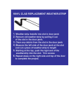
This manual courtesy of
Hudson-Essex-Terraplane Club member
Drew Meyer
I
FOREWORD
This Body Service Manual covers repair procedures applicable
to servicing the bodies of Hudson Cars from 1948 through 1954.
A detailed index is provided in which the parts and operations are
listed in alphabetical order under the assemblies or units to which they
belong. Illustrations and pages of this manual are numbered consecutively.
The times applying to body operations, as shown in the Flat Rate
Manual 1, are based on the procedures and operations covered in this
manual. Mechanics following these procedures and using the tools and
equipment available should have no difficulty in performing the operations in the time specified.
II
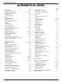
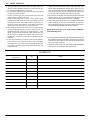
BODY MANUAL
ALPHABETICAL INDEX
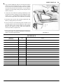
CONVERTIBLE
Adjustment, top control rod
Adjustments, top and window
Bleeding, the hydraulic system
Circuit breaker
Electrical system checks
Fluid level
Hydraulic pump prime
Hydraulic system
Hydro-Lectric service information.
Lock cylinder, door
Lock, door
Lock lubrication
Lock, remote control
Motor and pump assembly
Motor Hydro-Lectric and pump assy
Motor solenoid switch
Multiple switch units
Operating cylinder, top
Operating control valve, top
Operating switches, window
Outside handles
Outside mouldings (wide), header
Pressure relief and flow control valve Quarter
window regulator assembly,
rear
Refilling hydraulic system
Regulator assembly, door
window
Seat cushion and seat back, front
Seat cushion and seat back, rear
Service procedures
Top front header upper seal and top
front header moulding (wide)
Top front header lower seal
Top operating switch test
Top operating valve and switch assembly
Top and rear curtain
Top sealing
Top side rail weatherstrips
Trim panel, door
Trim panel, quarter
Trouble shooting
Valve switch assembly
Ventilator wing glass and frame
assembly, door
Ventilator wing regulator assy., door
Window and glass frame assy., door
Window lift control switch
Window power valve solenoid check
Window regulator cylinder
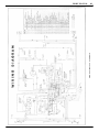
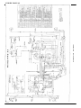
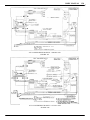
Wiring diagram - 1948-1953
Page
95
100
112,113,114,115
119
116
116
119
119
118
115,116
109
110
110
110
95,98
95,98
117
107
101,102
118,119
106
109
124
118
106
119
102,103,104
109
109
98
124
123
117
99
110
122
125,126
107,108
108
127,128
100
105
105
103
117
118
104
120
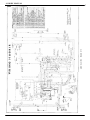
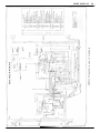
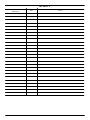
Wiring diagram - 1954
Wiring diagram, top operating
Wiring diagram, window regulator
and cylinder
DOORS
Adjustment, lock release button
Check arm
Door to body alignment
Front door complete
Front pillar seals
Glass, front door
Glass, rear door
Handle adjustment
Handle, outside
Liner, inner
Lock cylinder
Lock, front or rear
Lock, release button
Regulator, front window
Regulator, rear window
Remote control, front or rear
Sealing, scuff plate
Striker plate
Trim panel, door
Ventilator regulator, front
Ventilator regulator, rear
Ventilator wing
Weatherstrip belt seal, front
Weatherstrip, bottom
Weatherstrip, lower front
Weatherstrip opening, upper front door
Weatherstrip, front door
Weatherstrip, front (rear door)
Weatherstrip, rear door
Weatherstrip, rear opening, rear door
FENDER - FRONT
Extension
Stone guard and panel assembly
Tie panel
FENDER - REAR
FRAME AND BODY ALIGNMENT
Aligning and tramming, body
Alignment, door to body
Checking body door openings
Final check of body repair
Resealing after repair
Straightening doors
GENERAL INTERIOR - INFORMATION
ON APPEARANCE
Page
121
96
97
1
11
14
12,13
13,14
14
3
4
9,10
9
19
6
6,7
9
1,2
2,3
8
19
11,12
1
4,5
5
4,5,6
15
17
16
14,15
18
17
18
16
71
73
74
74
74,75
82
83,84,85
82
83
85,86
86
82
56
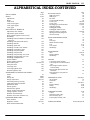
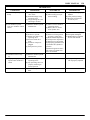
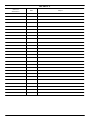
BODY MANUAL III
ALPHABETICAL INDEX-CONTINUED
HE AD LINING
Page
37,38
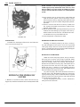
HOOD
Adjustments
Hinge
Lock, lower
Lock, lower support
Lock, upper support
Lock, upper
67,68
69
70
70
68
68
69
HOLLYWOOD - HARDTOP
Adjustment, door window
Adjustment, quarter window
Door window regulator cross arm assy
Headlining
Moulding, body front header to side header
joint cover
Moulding, body side header interior
Moulding, door belt
Moulding, quarter belt
Moulding, rear belt at rear window.
Moulding, rear window, upper
Moulding, roof panel quarter
Moulding, roof panel side
Moulding, roof panel drip cover, front
Moulding, roof panel drip cover, rear
Moulding, windshield lower
Quarter window
Quarter window regulator
Rear window glass
Trim panel, door
Vent wing, door
Vent wing regulator, door
Window regulator, door
129
129
132
129
136
134
134
134
134
134
135
135
135
135
135
135
131
131
132,133,134
129
130
130
129
INSTRUMENT CLUSTER AND PANE L
ASSY
Clock
Gauge, fuel
Gauge, temperature
Instrument panel top covering
Light switch and circuit breaker
Speedometer head
Switch, ignition
Switch starter, ignition
Switch, weather control blower
Voltage regulator, constant
Weather control assembly
Weather control lever and brkt. assy
47
48,49
49,50
50,51,52
54
52
48
53
53
53
50
53
53
QUARTER TRIM PANEL
Glass, window
Regulator, window
Water shed and drain baffle
33
35,36
34,35,36
34
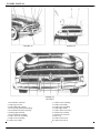
RADIATOR GRILLE
Baffle, side support
Baffle, upper
Bar, center
Louver and baffle assembly
Louver, lower
Louver, upper
Moulding, upper and intermediate
Ornament assembly
Parking light assembly
Parking light ornament or lens
Radiator mounting "U" channel ..
Splash guard and moulding, front
Structure assembly
REAR COMPARTMENT DOOR
Door
Door hinge
Handle and lock assembly
Lock
Lock cylinder
Weatherstrip
REAR WINDOW
Glass
Reveal mouldings
Weatherstrip
SEALING
Cowl panel to frame and pillar
Cowl side panel to toe board and frame
joint
Drain trough and quarter window
reveal moulding
Rear seat under panel to frame and
wheelhouse
Rear under panel to rear panel and
wheelhouse
WINDSHIELD GLASS
Air stop blocks
Drain tubes
Glass
Reveal mouldings
Sealing
Weatherstrip
WINDSHIELD WIPER
Control
Housing and cable, pulley
Motor assembly, wiper
Tension pulley assembly, cable
WIRING DIAGRAMS
Page
60
60
60
60
60
60,63,65
62,63,65
61,62,65
62
62
64
62,64,66
60
63
76
78
78
76
76,77
77,78
78
28
29,30,32
28,31
33
87
93
92
93
90
91
20,21,26,27
24
21
20,21,26,27
25,26
23,24
26,28
55,56
52
55
55
55
40,41,42,43,44,45,46
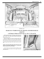
1 BODY MANUAL
DOORS
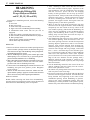
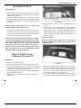
DOOR TRIM PANEL
(Front and Rear)
(Models 1948 thru 1954)
REMOVAL
1. Remove inside door handles.
2. Remove lock release knob and garnish moulding, (on cars
so equipped).
3. Remove two screws from underside of arm rest and remove arm rest.
NOTE: On all 1953 and 1954 models the arm rest is part of
the trim panel. Remove two screws from inside pocket
of arm rest.
4. Remove valance (on cars so equipped by extracting exposed screws and sliding valance up from between door
and trim panel.
5. Re move door pocket trim board (clips). (On cars so
equipped.)
6. Remove door panel held by (clips) using wide bladed putty
knife.
3. Install pocket trim board.
4. Install valance by inserting lower flange between door
and pocket trim board; and, with slots in line with trim
board clips, force valance down into position and install
screws.
5. Install arm rest, (on cars so equipped), garnish moulding,
lock release knob, and door handles.
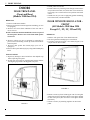
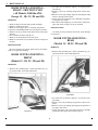
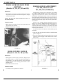
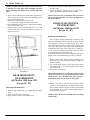
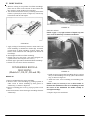
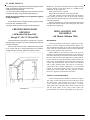
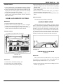
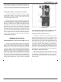
DOOR WINDOW REGULATOR FRONT
(All Models -1948 thru 1954
Except 1C, 1D, 2C, 2D and 3D)
REMOVAL
1. Remove trim panel. See "Trim Panel Removal".
2. Re move garnish moulding spacer wood block.
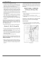
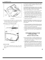
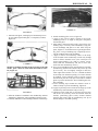
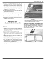
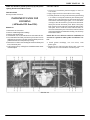
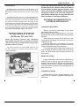
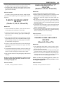
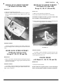
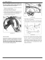
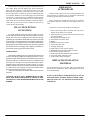
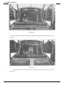
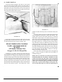
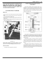
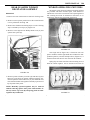
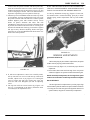
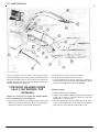
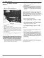
3. Cut liner as shown in Figure 1 for sedans, Figure 2, for
coupes and two door sedans.
INSTALLATION
1. Repair any damage to door inside liner with Mystik tape
before replacing trim panel.
2. In stall door trim panel by engaging the bottom retainer
and aligning clips before driving panel into place.
FIGURE 2
FIGURE 1
4. Remove screw (A) from inside upper end of center glass
channel and screws (B) which attach center glass channel
to door inner panel. (Do not remove center glass channel
from door.)
5. Remove screws (C) attaching regulator to door inner
panel.
BODY MANUAL 2
6. Lower window to bottom of door and release regulator
cross arms from glass channel on sedans. On coupes and
two door sedans disconnect regulator from cross arm
assembly. (A stud on the regulator arm is retained in the
cross arm assembly by a spring clip.)
7. Remove regulator through opening in bottom of door.
INSTALLATION
Reverse procedure of removal and repair damage to
door inner liner with Mystik tape
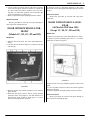
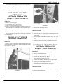
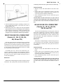
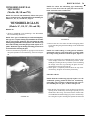
DOOR WINDOW REGULATOR FRONT
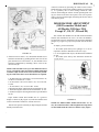
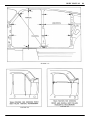
(Models 1C, 1D, 2C, 2D and 3D)
REMOVAL
1. Remove door trim panel. See "Trim Panel Removal",
Page 1.
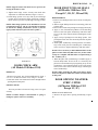
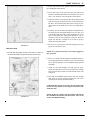
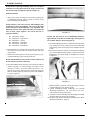
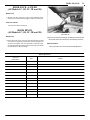
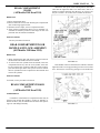
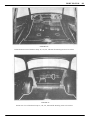
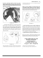
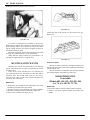
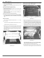
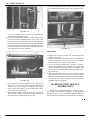
2. Cut inner liner as shown in Figure 3, to expose screws (C)
and hole (E).
5. Remove screws (C) attaching regulator to door inner
panel and remove the regulator through opening at bottom
of door.
INSTALLATION
Reverse the procedure of removal and repair door
inner liner.
DOOR WINDOW REGULATOR REAR
(All Models-1948 thru 1954
Except 1C, 1D, 2C, 2D and 3D)
REMOVAL
1. Remove trim panel. See "Trim Panel Removal", Page 1.
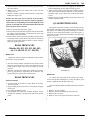
2. Remove garnish moulding spacer block. 3. Cut door
inner liner as shown in Figure 4.
FIGURE 4
FIGURE 3
3. Remove retainer clip from the regulator arm to window
glass channel.
4. Raise the door glass, insert a drift or punch, through
opening in door at (E) Figure 3, the drift should be so
placed below glass channel to hold glass in a raised
position when regulator is removed.
4. Remove four screws (A) holding regulator to door inner
panel.
5. Lower window to bottom of door and release regulator
from glass channel.
6. Remove regulator through opening at bottom of door.
INSTALLATION
Reverse procedure of removal and repair damage to
door inner liner with Mystik tape.
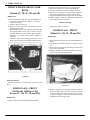
3 BODY MANUAL
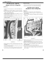
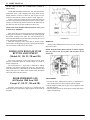
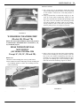
DOOR WINDOW REGULATOR REAR
(Models 1C, 1D, 2C, 2D and 3D)
REMOVAL
1. Remove door trim panel. See "Trim Panel Removal".
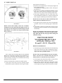
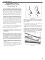
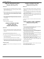
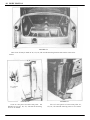
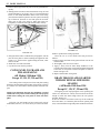
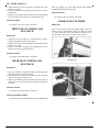
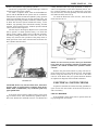
2. Cut inner panel as shown in Figure 5, to expose
screws (G) and (H).
3. Remove the one screw (G).
4. Remove retainer clip from the regulator arm to
window glass control.
5. Raise the door glass, insert a drift or punch through
the opening where screw (G) has been removed.
The drift should be so placed below glass channel to
hold glass in a raised position when regulator is
removed.
6. Remove screws (H) attaching regulator to door
inner panel and remove the regulator through opening at bottom of door.
2. Remove small wood block (on cars so equipped).
3. Remove trim panel, see "Trim Panel Removal".
4. Cut door inner liner as shown in Figures 1 and 2.
5. Remove screw (A) and two screws at (B). 6. Remove
center glass channel (D) or lower it into the door.
7. Tilt glass inward and raise to upper limit of regulator.
8. Release regulator cross arms from glass channel and
remove glass and glass channel.
INSTALLATION
Reverse procedure of removal.
DOOR GLASS - FRONT
(Models 1C, 1D, 2C, 2D and 3D)
REMOVAL
1. Remove door trim panel. See "Trim Panel Removal",
Page 1.
2. Cut inner liner as shown in Figure 3, to expose screws
(D).
3. Remove the two screws (D) attaching center bar glass
run to door inner panel.
4. With the door glass in the down position, remove the
retainer clip from the regulator arm.
FIGURE 5
INSTALLATION
Reverse procedure of removal and repair door inner
liner.
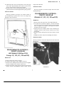
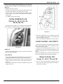
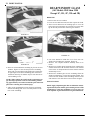
DOOR GLASS - FRONT
(All Models 1948 thru 1954
Except 1C, 1D, 2C, 2D and 3D))
REMOVAL
1. Remove safety lock knob and garnish moulding.
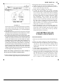
FIGURE 6
5. Remove regulator arm from glass channel, bring the
door glass down and at the same time turn the glass
1/4 turn to bring the narrow side of glass to the top,
as shown in Figure 6. Tilt glass inward and remove
through the top opening in door.
BODY MANUAL 4
INSTALLATION
To install, reverse procedure of removal.
DOOR GLASS - REAR
(All Models 1948 thru 1954
Except 1C, 1D, 2C, 2D and 3D)
REMOVAL
1. Remove safety lock knob and garnish moulding.
2. Remove small wood block.
3. Run glass to within 2" of the top. and pull inward on top of
glass to release glass from glass runs.
4. Tip glass inward and raise window until glass channel can
be released from regulator.
5. Remove glass and glass channel.
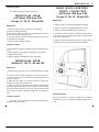
DOOR VENTILATOR WING
FRONT - CRANK TYPE
(All Models 1948 thru 1954
Except 1C, 1D, 2C, 2D and 3D)
-
REMOVAL
1. Remove safety lock knob and garnish moulding.
2. Remove ventilator regulator handle and valance.
3. Remove garnish moulding spacer wood block.
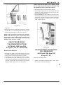
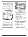
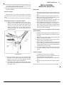
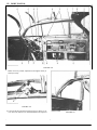
4. Cut hole in door inner liner as shown at (B) in Figure
7, to expose clevis (G) connecting wing to regulator and
remove screw from clevis.
5. Open ventilator wing and press down on top of frame
to release it from upper pivot and lift out ventilator.
INSTALLATION
1. Insert channel and glass through opening and engage regulator.
2. Run regulator up and down to work glass into position.
3. Replace wood block.
4. Replace garnish moulding and safety lock knob.
DOOR GLASS - REAR
(Models 1C, 1D, 2C, 2D and 3D)
REMOVAL
1. Remove door trim panel. See "Trim Panel Removal", Page
1.
2. Cut inner liner as shown in Figure 5, to expose screws (J).
3. Remove the two screws (J) attaching center bar glass run to
door inner panel.
4. With the door glass in the down position, remove the
retainer clips from the regulator arm.
5. Remove regulator arm from glass channel and bring the
door glass down, at the same time, turn glass 1/4 turn to bring
the narrow side of the glass to the top. Tilt glass inward and
remove glass and glass channel through the top opening in
door.
INSTALLATION
To install, reverse procedure of removal and repair any
damage to door inner liner.
FIGURE 7
INSTALLATION
Reverse procedure of removal. Make sure ventilator
weatherstrip lip is over garnish moulding. Repair inner
liner.
5 BODY MANUAL
DOOR VENTILATOR WING FRONT - FRICTION TYPE
(All Models 1948 film 1954
Except 1C, 1D, 2C, 2D and 3D)
REMOVAL
1. Remove safety lock knob and garnish moulding.
2. Remove wood spacer block.
3. Remove screws (B), Figure 1, attaching wing frame.
4. Re move small Phillips head screw (D), from top of door.
5. Remove screw (A), from inside upper end of center glass
channel.
6. Tilt ventilator assembly and lift out.
7. Remove nut and spring from friction pivot.
8. Remove screw from top of channel to release wing from
channel.
INSTALLATION
Reverse procedure of removal. Make sure lip of weatherstrip is over garnish moulding.
DOOR VENTILATOR WING FRONT
(Models 1C, 1D, 2C, 2D and 3D)
2. Cut inner liner as shown in Figure 3, to expose screws
(D) and (G).
3. Remove screw (G), attaching wing frame to door inner
panel.
4. Remove screws (A) and (B), Figure 8, attaching the wing
frame to the upper door frame.
5. Grasp center bar and pull back to dislodge wing frame
from upper door frame.
6. Pull inward and straight up, to remove door wing frame,
glass and center bar glass run as an assembly.
INSTALLATION
To install, reverse procedure of removal, repair damage
to inner liner.
DOOR VENTILATOR WING REAR
(Models 1C, 1D 2C, 2D and 3D)
REMOVAL
1. Remove door window glass - follow operations (1), (3),
(4) and (5) under "Door Glass Removal".
REMOVAL
1. Remove door window glass - follow operations (1), (3),
(4) and (5) under "Door Glass Removal"
FIGURE 9
FIGURE 8
2. Cut inner liner as shown in Figure 5, to expose screws
(F) and (J).
3. Remove screw (F) attaching wing frame to door inner
panel.
4. Remove screws (A) and (B) attaching the wing frame to
the upper door frame.
5. Grasp door glass center bar and pull back to dislodge
wing frame from upper door frame, Figure 9.
BODY MANUAL 6
Pull inward and straight up to remove door wing frame,
glass and center bar glass run channel as an assembly.
INSTALLATION
Reverse procedure of removal and repair door inner liner.
DOOR VENTILATOR WING
REGULATOR
(All Models 1948 thru 1954
Except 1C, 1D, 2C, 2D and 3D)
REMOVAL
1. Remove door trim panel.
2. Cut door inner liner at (B), Figure 7.
3. Remove screw from regulator clevis.
4. Remove two screws (F) attaching regulator to door inner
panel and remove regulator down and out through opening in bottom of door inner panel.
FIGURE 11
2. Pull out lock cylinder assembly.
INSTALLATION
INSTALLATION
Reverse procedure of removal and repair door inner liner
with Mystik tape.
DOOR LOCK CYLINDER
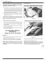
(All Models 1948 thru 1954)
1. From inside of door, insert a piece of pointed spring steel
wire through the hole (C), Figure 10, in the door to the
outside panel.
2. Place recessed end of lock on the point of the wire, pilot
the lock cylinder shaft, at the same time withdrawing the
wire.
3. With lock cylinder in position, install the lock retainer.
REMOVAL
1. Insert a screw driver between the flanged end of the lock
retainer and door panel and pry retainer (B), Figure 10 and
(A), Figure 11, outward.
DOOR LOCK - FRONT OR REAR
(All Models 1948 thru 1954
Except 1C, 1D, 2C, 2D and 3D)
REMOVAL
1. Remove outside door handle.
2. On front doors, remove door lock cylinder.
3. Remove door trim panels, see Page 1.
4. Cut door inner liner at (A), Figure 7, and disconnect
remote control arm from lock at (D).
5. Remove door window channel from lock side of door.
6. Remove three large Phillips head screws
(C) from edge of door and remove lock assembly down and
out through lower opening in door inner panel.
INSTALLATION
FIGURE 10
Reverse the procedure for removal. Repair any damage
to inner liner with Mystik tape.
7 BODY MANUAL
DOOR LOCK - FRONT
(Models 1C, ID, 2C, 2D and 3D)
REMOVAL
1. Remove door trim panel, see "Trim Panel Removal",
Page 1.
2. Cut inner liner as shown in Figure 3, to expose screws (D).
3. Remove window glass - follow operations (3), (4) and (5)
under "Door Glass Removal" .
4. Remove retainer clip from door lock cylinder, see "Lock
Cylinder Removal", Figure 11.
5. Remove retainer spring (A), attaching the remote control
link to door lock, Figure 12.
6. Remove two screws (H), attaching the upper door frame
to door assembly.
INSTALLATION
1. Reverse procedure of removal, repair door inner liner.
2. Install door trim panel. See "Trim Panel Installation".
DOOR LOCK - REAR
(Models 1C, 1D, 2C, 2D and 3D)
REMOVAL
1. Remove door trim panel. See "Trim Panel Removal".
2. Cut inner liner as shown in Figure 5, to expose screws (D),
(E), (F) and (J).
3. Remove retainer spring (D), attaching remote control link
to door lock.
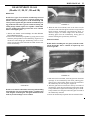
FIGURE 13
FIGURE 12
7. Remove three screws (F), attaching the door lock to door
assembly.
8. From inside of door, pull back on upper door frame, push
door lock inward and down.
9. Turn lock 1/4 turn to by-pass upper door frame anchor
plate and remove lock through bottom opening in door.
4. Remove screw (A) attaching lock release rod pivot to door
inner panel, Figure 13.
5. Remove cotter pin attaching lock connector rod to pivot.
6. Remove screw (F) attaching wing frame to door inner panel.
7. Remove two screws (J) attaching center bar glass run to
door inner panel.
8. Cut weatherstrip at (C) as shown in Figure 13.
9. Remove two screws at (A) and the three screws at the front
section of the door attaching the upper door frame to the
door assembly.
BODY MANUAL 8
10. With door glass in the raised position, raise the upper
door frame approximately four inches to allow clearance to remove the rear door lock assembly.
11. Remove three screws at (B) attaching door lock to door
panel and remove lock through bottom opening in door.
INSTALLATION
Reverse procedure of removal, use rubber cement to
join weatherstrip at points where it was cut. Repair any
damage to door inner liner.
hinge side of the door.
INSTALLATION
Reverse procedure of removal. Repair door inner liner
with Mystik tape.
DOOR REMOTE CONTROL FRONT OR REAR
(Models 1C, 1D, 2C, 2D and 3D)
REMOVAL
1. Remove door trim panel. See "Trim Panel Removal" .
2. Cut inner liner as shown in Figure 3, for the front door
to expose screws (B) and retainer spring (A) for the front
door, or Figure 5, to expose screws (K) and retainer
spring (D) for the rear door.
3. Remove the three Phillips head screws attaching the
triangular bracket of the remote control arm to door
inner panel.
4. Remove retainer spring from lock end of remote control
arm.
5. Withdraw remote control toward hinge side of door.
INSTALLATION
Reverse procedure of removal. Repair door inner liner with
Mystik tape.
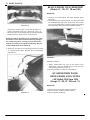
FIGURE 14
DOOR REMOTE CONTROL FRONT OR REAR
(All Models 1948 thru 1954
Except 1C, 1D, 2C, 2D and 3D)
REMOVAL
1. Remove door trim panel, see Page 1.
2. Cut door inner liner at (A) in Figures 7 and 14.
3. Remove three Phillips head screws (E) from triangular
bracket at handle end of remote control arm.
4. Remove anti-rattle spring and pin (D) from lock end of
remote control and withdraw remote control toward
hinge
FIGURE 15
9 BODY MANUAL
DOOR LOCK RELEASE PUSH
BUTTON
(Models 1C, 1D, 2C, 2D and 3D)
DOOR HANDLE ADJUSTMENT
(All 480, 490 Series and
501, 502, 503, 504 Models)
REMOVAL
1. Through the access hole in the door behind the weatherstrip, insert a screw driver as shown in Figure 15, and pry
out door push button.
NOTE: The door push button retainer also can be removed at this time.
INSTALLATION
1. With retainer in position, line up door push button and
snap retainer into position.
2. Reglue weatherstrip as necessary
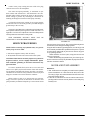
The operation of a door lock is effected b y the relation
of the door handle shoulder screw to the surface of the
trigger lever of the door lock. If there is too much clearance
(lock handle outside push button in the rest position) between the trigger and the shoulder screw at (A), Figure 17,
the door lock will not release properly when the outside
handle push button (K), Figure 18, has been pushed in to
its full travel.
If there is not enough clearance (shoulder screw (L),
Figure 18, is too long, holding the lock trigger, Figure 17,
inward from its free position), it will be impossible to
unlock the door either with the key or the door lock release
button (button cannot be raised) after the door has been
locked by either method.
To check the door lock and door outside handle proceed
as follows:
1. Open the door and raise the lock bolt to the full latched
position, Figure 17.
2. Press the outside handle push button (K), Figure 18, until
contact at the lock trigger is felt. Measure this travel as
shown at (s).
FIGURE 16
DOOR OUTSIDE. HANDLE
(Models 1C, 1D, 2C, 2D and 3D)
REMOVAL
1. Through the access hole (A) in the door, Figure 10 (for
all models except 1C, 1D, 2C, 2D and 3D) and Figure 16
for (Models 1C, 1D, 2C, 2D and 3D), remove the door
handle retaining screw attaching door handle to door
outside panel.
2. Pull handle forward and out.
INSTALLATION
To install, reverse procedure of removal.
FIGURE 17
BODY MANUAL 10
cannot be released by operating the inside remote control
handle after the car has been standing outside in cold weather, it is probably due to water having soaked the cloth
silencer surrounding the remote control operating link causing it to freeze to the door inner panel. This can be permanently corrected by thoroughly saturating the silencer sleeve
with chassis grease.
DOOR HANDLE ADJUSTMENT
(500 Pacemaker Models and
All Models 1951 thru 1954
Except 1C, 1D, 2C, 2D and 3D)
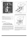
The outside door handles for the 500 model Pacemaker
and the door handles for the "1951 "A" Series all Models",
are identical except for the distance the end of the adjustable
plunger (Y), Figure 19, projects beyond the base of the handle.
To adjust, proceed as follows:
FIGURE 18
3. If the travel is less than 1/16", the handle shoulder screw
should be shortened by grinding off the inner end. If the
push button travel is more than 1/4", the shoulder screw
should be lengthened by installing a drive screw in the
inner end at (Y).
a. All sedans (front doors) turn plunger in or out as
required to obtain a dimension of 23/32" at (X).
b. A 11 broughams and coupes, this dimension should be
51/64".
c. All sedans (rear doors), this dimension should be
1-7/32" at (V).
NOTE: If the shoulder screw (L) is not drilled for a drive
screw, it should be removed from the handle and drilled
as shown at (R). Excess travel can be corrected by installing one of the three drive screws listed below as required.
a. If dimension (S) is more than 5/16" but less than 3/8",
use drive screw Part No. 171221.
b. If more than 3/8" but less than 7/16", use screw No.
171222.
c. If more than 7/16", use screw No. 71249.
d. Dimension (X) for sedan front doors should be 51/64".
e. Dimension (X) for sedan rear doors should be 1-11/32".
f. Dimension (X) for all broughams and coupes should be
29/32".
Super model outside door handles are of a grooved
design as shown at (H), Figure 18, while the handles used
on the Commodore models are smooth and oval.
If door lock operates normally by depressing the outside
handle push button but
FIGURE 19
NOTE: For 500 Pacemaker models and all 1951 "A" Series, the sedan front doors and brougham and coupe doors
use the handle with the contour as shown at (N), Figure
11 BODY MANUAL
19. The sedan rear door uses a handle with a contour as
shown at (U).
On the 480-490 Models and the 501, 502, 503, 504 models,
sedan front door s and brougham and coupe doors use the
handle with the contour as shown at (M), Figure 18. The
sedan rear door handle contour is shown a t (N), Figure 18.
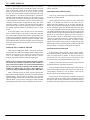
Failure of the lock to hold the door closed may be due to
the door rotor latch being held open because of lack of lubrication or to water having frozen on the lock. Re-lubrication of
the door lock will correct the condition in either case.
NOTE: Door locks should be lubricated at least twice a year
or about every 5000 miles.
This can be done by removing the door outside handle and
cleaning the lock with air, inserting the hose nozzle through
the handle opening in the door. The lock should then be
FIGURE 20
lubricated with Hudson Lock-Ease Oil by inserting the oil can
spout through the handle opening.
With the exception of the correction of frozen remote REMOVAL
control links, the foregoing operations can be performed withRemove three Phillips head screws (1) from striker plate
out removing the inside trim or door locks.
and remove plate.
DOOR LOCK RELEASE PUSH
BUTTON ADJUSTMENT
(Models IC, 1D, 2C, 2D and 3D)
NOTE: With the striker plate removed, to remove tapping
plate (2), loosen trim (4) at pillar and lift plate out of
retainer (5).
The proper operation of the front and rear door push
buttons is obtained when the measurements are made as
shown in Figure 20.
The measurement a t upper left is obtained by adding
washers 1/32" thick as required, at point "A". The measurement shown below is controlled by the threaded plunger and
button. The object is to effect a door release before the button
outer end passes into the retainer.
FIGURE 21
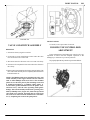
DOOR STRIKER PLATE
(All Models 1948 thru 1953
Except 1C, 1D, 2C, 2D and 3D)
The door striker plate (3), Figure 21, is mounted on the
body pillar and is attached to a tapping plate on the inside of
the pillar.
ADJUSTMENT
1. Loosen the three, Phillips head screws (1) sufficiently to
allow striker plate to be moved easily with the fingers.
2. Adjust height of striker plate to give correct alignment with
the door latch bar.
3. Adjust inward position of striker plate to hold door firmly
against weatherstrips.
BODY MANUAL 12
NOTE: When making inward adjustment, be sure that back
of striker plate is parallel to the inside flange of the body
pillar (A).
4. Tighten screws (1) securely.
5. Close door to bring latch bar into safety catch position. Door
should not open when a reasonable pull is exerted.
6. If door opens easily without pushing the handle button,
loosen screws as in step one and rotate bottom of striker
plate inward
(C). Tighten screws and recheck.
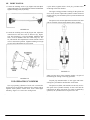
DOOR STRIKER PLATE
(Models 1C, 1D, 2C, 2D, 3D,
4D, 5D and 7D)
The door striker, Figure 22, is mounted on the body pillar
and is attached to a tapping plate on the inside of the pillar.
FIGURE 23
4. The above adjustments can be made by loosening
the two Phillips head screws (C) attaching the
striker assembly to the pillar.
5. After each adjustment, tighten the screws securely.
DOOR TO BODY ALIGNMENT
FIGURE 22
REMOVAL
Remove two Phillips head screws from the door striker and
remove the striker assembly.
ADJUSTMENT
1. Up or down adjustment will determine the actual point of
engagement between the door lock rotor and the striker.
2. If the door lifts as the dovetail (A), Figure 23, enters the door
striker assembly, (B) the striker is too high and must be
lowered.
3. The in and out adjustment controls the tightness of the door
against the body.
Proper door alignment prolongs the life of the door
locks, striker plates, check arms, and hinges and assures ease of door operation.
Check to see that the door properly con- t a c t s the
weatherstrips at the door header weatherstrip, door
opening weatherstrip and/ or the door bottom weatherstrip.
Examine all weatherstrips to make sure they are firmly
and evenly attached to doors and door openings.
(Models 1948 thru 1954
Except 1C, 1D, 2C, 2D and 3D)
1. If door is away from the pillar at the lock side of
door, move the striker plate inward according to
instructions on Page 11.
13 BODY MANUAL
2. A door that is out of alignment at the top
3. or bottom may be adjusted by loosening the screws
attaching the hinge to the hinge pillar and moving the
hinges in or out as required. (Replace any shakeproof
washers damaged in the adjustment process.)
4. Further adjustment at the lock side of the door may be
made by placing a small block of wood or a rubber
mallet against the top or bottom of the door opening and
closing the door on the block. This will spring the door
out slightly where it bears against the block. It may be
necessary to close the door against the block several
times while pressing firmly on part of the door that must
be sprung inward.
5. Door flanges may be adjusted inward by hammering
with a rubber mallet. It is advisable to protect painted
surfaces with masking tape before hammering.
6. In severe cases of door misalignment it may be necessary
to bend or straighten the hinge, using a suitable hinge
bending tool.
NOTE: Be sure hinge attaching screws are tight before
applying the hinge bending tool. To raise the door at the
lock pillar, bend the t op hi n g e outward; to lower the
door, bend hinge inward.
6. Re-adjust striker plate upon completion of door adjustment.
To move the upper section of the door ahead or back,
loosen the upper hinge screws, to move the lower section,
loosen the lower hinge screws and push or pull the door in
the desired direction. Retighten hinge screws securely after
adjustments.
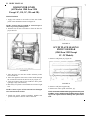
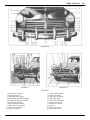
FRONT DOOR - COMPLETE
(All Models 1948 thru 1954)
REMOVAL
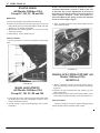
1. Remove hinge pocket covers (D) and (E), Figure 24, on
models so equipped.
2. Drill out check arm rivet (F) using a 1/4" drill.
3. Loosen the hinge screws at the door half of hinge and
remove door.
NOTE: Have a helper hold the door in alignment while
removing screws to prevent screws from stripping.
INSTALLATION
1. In stall all hinge attaching screws and tighten slightly.
2. Attach check arm to check arm bracket using check arm
rivet. Peen rivet securely.
(Models 1C, 1D, 2C, 2D and 3D)
1. To raise or lower the door, place a jack as near the hinge
as possible (this will hold the weight of the door as the
hinge screws are loosened).
2. Use an awl to scribe around the upper and lower hinges
before loosening the hinge to front pillar screws, this will
insure proper horizontal alignment after vertical adjustments have been made.
3. Loosen the upper and lower hinge screws.
NOTE: The amount of vertical hinge movement is very
limited. Do not damage the door with the jack when
making this adjustment.
4. Raise or lower the jack until the desired clearance i s
obtained, then tighten hinge screws securely. Check the
scribe marks to make certain the rear section of the door
did not move forward or rearward during the above
operation.
FIGURE 24
BODY MANUAL 14
NOTE: Support bracket and check arm to prevent distorting the bracket or arm.
3. Tighten door hinge screws securely and check door
adjustment as outlined in Manual, Pages 11 and 12.
4. Install hinge pocket covers (D) and (E) and fill hinge
pockets above and below hinges with body caulking.
Sealer must not project beyond edges of hinge pockets.
NOTE: These hinge pockets can be installed on cars not
so equipped except 1C, 1D, 2C, 2D and 3D. See Figures
24 and 25 for drilling instructions. (Insert (1) for the
upper pocket and insert (2) for the lower pocket.)
DOOR FRONT PILLAR SEALS
(All Models 1948 thru 1954
Except 1C, 1D, 2C, 2D and 3D)
REPLACEMENT
1. Remove two Phillips head screws at front of scuff plate,
Figure 24.
2. Remove eight Phillips head screws attaching pillar seal
to front pillar.
3. Remove all cement and permagum at hinge pockets (H).
4. Apply a coat of weatherstrip adhesive to the attaching
surface of the front pillar weatherstrip and allow adhesive to set for a few minutes before installing the weatherstrip.
5. Apply a strip of permagum in each hinge pocket . The
permagum sealer must not extend beyond area of pillar
weatherstrip.
6. Install pillar weatherstrip entering bottom of weatherstrip under scuff plate and installing the weatherstrip
lower screw first. Align weatherstrip with other holes.
NOTE: If it is necessary to drill additional holes in the
pillar on some of the early 480 series cars, use the weatherstrip as a template and drill holes as required using a
No. 34 drill (.111").
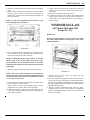
FIGURE 25
DOOR CHECK ARM
(All Models 1948 thru 1954)
REMOVAL
1. Remove trim panel. See "Trim Panel Removal", Page 1.
2. D r i 11 out door check arm rivet, using a 1/4" drill.
3. Push door check arm inward and remove through bottom
opening in door inner panel.
INSTALLATION
Reverse procedure of removal. Using a new rivet peen
securely.
NOTE: If rubber bumper is deteriorated or spring is
damaged, replace with a new assembly.
7. When the pillar seal (weatherstrip) is installed, apply a
bead of Body Sealer in base of the "V" formed by the
pillar face and weatherstrip lip beginning at top of the
weatherstrip, and continuing down to the lower hinge
and over the outer surface of lower hinge continuing to
end of weatherstrip.
NOTE: When replacing the pillar seals always check
front of scuff plate to make sure seal has not been broken
at that point.
DOOR OPENING WEATHERSTRIP - UPPER
(All Models 1948 thru 1953
Except 1C, 2C)
REMOVE AND REPLACE
1. Remove the upper door opening weatherstrip, Figure
26.
15 BODY MANUAL
strip, Figure 26, Insert No. 2.
4. Check to be sure weatherstrip is of the proper length and
for the right or left side
as required before applying rubber cement. See Figure
26, Insert No. 1.
5. Apply an even coating of weatherstrip adhesive to the
body and two sides of rubber weatherstrip. Allow rubber
cement to become tacky before installing weatherstrip.
6. Press upper weatherstrip into rear corner above rear
vertical weatherstrip (Insert No. 2) and proceed forward
until complete weatherstrip has been firmly installed.
NOTE: Do not close door on rubber weatherstrip until
rubber cement has sufficient time to set.
FIGURE 26
NOTE: On the earlier models, remove the "S " Rubber
attached to the cowl panel and front fender rear face at
(6), Figure 24, and roll portion of fender flange forward
approximately 1/4" and 2-3/16" long as shown on Figure 27, Insert (1).
7. Trim upper end of rear door front vertical weatherstrip
to follow contour of door opening upper weatherstrip
lip.
8. Apply rubber cement to top end of the rear door vertical
weatherstrip and seal end firmly to door opening upper
weatherstrip.
NOTE: On complaints of dust and water leaks at door
opening and scuff plates; check door opening weatherstrip, pillar and belt seals, also proper door closing and
scuff plate sealing.
FRONT DOOR FRONT
WEATHERSTRIP BELT SEAL
(All Models 1948 thru 1954
Except 1C, 1D, 2C, 2D and 3D)
REMOVE AND REPLACE
FIGURE 27
This is done to prevent sharp edges of cowl and fender
flanges from cutting the front door front weatherstrip at
belt line. See "Front Door Belt Seal Replacement". Clean
surface formerly covered by the "S" Rubber and touch up
with body color as required.
2. Remove all old rubber cement (use mineral spirits).
3. Loosen upper end of the rear door opening vertical
weatherstrip to permit installation of the upper weather-
1. Turn down upper end of front rubber front weatherstrip
lower and put door belt rubber weatherstrip end (2),
Figure 28, i n place engaging the lower clip of weatherstrip in hole near top of door channel.
NOTE: If the early 480 models do not have this hole,
drill a 1/4" hole 5/16" centerline from outer edge of
channel and 5/8" centerline from top of channel.
2: Cut off upper end of door front rubber to match lower
end of new belt rubber, Figure 27, Insert (2).
3. Apply rubber cement to back face and top face of belt
seal from lower edge of seal (edge of trough in rubber)
to back edge and to upper end of the front door weather-
BODY MANUAL 16
NOTE: If the door belt rubber is to be replaced, install
the door front lower weatherstrip first and follow with
the installation of the front belt seal as outlined.
1. Remove old rubber cement from door channel.
2. Apply rubber cement to the new weatherstrip and to the
weatherstrip channel allowing cement to become tacky
before installing weatherstrip.
5. Install weatherstrip to door channel; top end of lower
weatherstrip should be glued to bottom end of belt seal
weatherstrip. Turn the tabs down and recheck operation
of doors and adjust as required. See "Door Adjustment", Pages 11 and 12.
FIGURE 28
strip lower.
4. Install door belt seal, pressing seal into place and installing three No. 8 x 7/16" binding head sheet metal screws
through tabs and bend clip in door front channel.
NOTE: If the early models do not have these tab holes
drilled in the door inner panel, hold the belt rubber
weatherstrip in place firmly against the door front
flange. Mark location for drilling tab screw holes and
drill three holes .120" (No. 31 drill).
FRONT DOOR FRONT
WEATHERSTRIP LOWER
(All Models 1948 thru 1954
Except 1C, 1D, 2C, 2D and 3D)
REMOVE AND REPLACE
1. Working from inside of car with front door open to its
full width, straighten the lower tab located below lower
hinge and one tab below upper hinge, Figure 28.
2. Straighten the tab retaining the lower end of the door
belt moulding and pull weatherstrip free from door
channel. Separate the door lower weatherstrip from the
door belt weatherstrip at the point where they are glued
together. (Make a good clean cut at that point.)
FIGURE 29
REAR DOOR REAR OPENING
WEATHERSTRIP
(All Models 1948 thru 1953
Except 1C, 2C)
REMOVE AND REPLACE
1. Remove two Phillips head sheet metal screws, Figure
29, and remove the old weatherstrip.
17 BODY MANUAL
NOTE: On some of the early models it may be necessary
to drill the two 7/64" holes when installing t he latest
type weatherstrip. See Figure 29 for location of the two
holes.
door channel but do not install weatherstrip until cement
becomes tacky.
4. Install weatherstrip inserting clips in order shown,
Figure 30, working rubber firmly into channel.
2. Apply rubber cement to door pillar and to weatherstrip.
Allow cement to become tacky before attaching weatherstrip to body door pillar.
3. Attach clips in drilled holes using two No.
6 x 1/4" Phillips binding head sheet metal screws.
4. Press weatherstrip into position working from attaching
clips towards both ends.
5. Trim the upper end of the weatherstrip to f o 11 o w the
contour of the door opening weatherstrip as shown in
Figure 26, Insert 2.
NOTE: If it is necessary to drill these holes on some of
the early models, drill four 1/4" holes spacing holes as
shown in Figure 30.
DOOR PANEL BOTTOM
WEATHERSTRIP
(All Models 1948 thru 1953
Except 1C, 2C)
REMOVE AND REPLACE
After the door opening weatherstrips and pillar seals
have been installed and doors checked for proper closing
and alignment, check the sealing quality of the door
bottom weatherstrip using a shipper's tag or calling card
.010" thick, placing the card between the double lipped
weatherstrip and rocker panel extension. If sealing is
correct, card can be pulled out with little effort but cannot
be inserted without reopening the door.
If the weatherstrip does not contact throughout the entire
length, install a new double-lip type rubber as follows:
1. Remove the stainless steel (painted) moulding from
bottom of door. Use a hardwood wedge to lightly pry
off the moulding.
2. Use a small sharp chisel to remove the flared ends of
the weatherstrip rivets at the moulding retainers and
remove retainers.
3. Remove the weatherstrip.
FIGURE 30
REAR DOOR FRONT
WEATHERSTRIP
(All Models 1948 thru 1953
Except 1C, 2C)
REMOVE AND REPLACE
1. Remove old weatherstrip by straightening attaching
clips.
2. Remove all old cement from metal.
3. Apply rubber cement to weatherstrip and
NOTE: The weatherstrip is cemented as well as riveted
and it is necessary to pry the weatherstrip loose from
inside of door. Care should be used when prying to
eliminate any distortion of the door outer panel.
4. Remove old cement, dirt and rust and apply rubber
cement to the double-lip type weatherstrip and to the
door. Cement should be applied to the top and outside
of weatherstrip for its entire length and positioned as
shown in insert, Figure 31.
NOTE: Allow cement to become tacky before installing
weatherstrip.
BODY MANUAL 18
weatherstrip and the door inner panel and remove weatherstrip.
INSTALLATION
1. Remove all dirt and dried adhesive from door inner
panel.
2. Apply a thin coat of weatherstrip cement to the door
inner panel and the weatherstrip; allow cement to become tacky before installing weatherstrip.
3. Press weatherstrip firmly in place and bend up the
bottom retainer.
FIGURE 31
5. Install weatherstrip and place moulding. retainers over
rivets. Install plain washers 1/32" thick over rivets at
elongated holes only.
6. When flaring rivets, have a helper use a ball peen hammer
against head area of rivet to avoid damage to the weatherstrip.
7. After installing weatherstrips, install the mouldings and
check sealing of weatherstrip as outlined in the first
paragraph of "Door Panel Bottom Weatherstrip Installation".
FRONT DOOR WEATHERSTRIP
(Models 1C, 1D, 2C, 2D, 3D,
4D, 5D and 7D)
The door upper and lower weatherstrip are two separate
pieces vulcanized to form a one piece weatherstrip. The
weatherstrips are mounted on the doors and are cemented
to the door inner panel. The lower (bottom) weatherstrips
a re also held in position with retainers bent over to hold
the weatherstrip to the door panel.
On Models 4D, 5D, 7D the belt weatherstrip ("S"
rubber) is similar in design to the weatherstrip used on
earlier models. The front door front weatherstrip lower is
the same as used on earlier models. See Page 15 for removal and installation.
REMOVAL
Bend down scalloped edges of retainer along the bottom
of the door. Use a putty knife, break the seal between the
NOTE: Make sure door drain slots are open and not
covered by the weatherstrip or the bottom retainer. Do
not close doors until cement has had sufficient time to
dry.
REAR DOOR WEATHERSTRIP
(Models 1C, 1D, 2C ,2D, 3D,
4D, 5D and 7D)
The rear door weatherstrips are in two pieces. The rear
door lower weatherstrip is held in position by retainers
that have scalloped edges that are bent over the weatherstrips after the weatherstrips have been cemented to the
door inner panel. The upper weatherstrip is cemented to
the inner door panel.
REMOVAL
Bend down scalloped edges of retainer along the bottom of the door. Use a putty knife , break the seal between
the weatherstrip and the door inner panel and remove
weatherstrip.
INSTALLATION
1. Remove all dirt and dried adhesive from door inner
panel.
2. Apply a thin coat of weatherstrip cement to the door
inner panel and the weatherstrip; allow cement to dry
until tacky and install weatherstrip.
3. Press weatherstrip firmly in place and bend up the
bottom retainer.
NOTE: Make sure door drain slots are open and not
covered by the weatherstrip or the bottom retainer. Do
not close doors until cement has had sufficient time to
dry.
19 BODY MANUAL
DOOR INNER LINER
(All Models 1948 thru 1954
Except 1C, 1D, 2C, 2D and 3D)
INSTALLATION
1. Apply trim cement to the surface of the door inside
panel in the shaded area shown in Figure 32.
NOTE: Cement must be applied in vertical strips as
shown to prevent pocketing water.
2. Fold the liner on the scored lines to form the liner for
proper door fit.
FIGURE 33
SCUFF PLATE SEALING
FRONT OR REAR
(1948 thru 1953 Except
1C - 2C Models)
1. Remove scuff plates (A), Figure 34.
FIGURE 32
3. Place the liner over the door surface with the pocket
area located first.
4. Insert the regulator and remote control shafts through
the scored and cut holes in the liner at (A), Figure 33.
5. Tuck the bottom ends of liner inside the door panel
openings at (B). (Do Not Seal.)
6. Rub firmly over panel at cemented areas to insure a tight
seal.
NOTE: Cement a piece of liner material over damaged
areas and extra holes in liner.
7. Install trim panels, garnish mouldings, handles and
pocket trim panel in reverse order of removal.
FIGURE 34
2. Remove scuff plate supports (B).
3. Remove the rocker panel extensions, (C).
NOTE: On the 480 and 490 models equipped with rocker panel
mouldings, remove and discard the mouldings as these mouldings are not required with the double-lip door panel bottom
seals.
BODY MANUAL 20
4. Remove old sealer and dirt from frame side rail and pillar
posts.
5. Apply rubber cement to the rocker panel extension rubber
seals (F); allow cement to become tacky and install as
shown at (F), Figure 34, for the front doors and Figure 35,
for the rear doors.
NOTE: Use the latest moulded type seals. Refer to your
Parts Catalogue for part numbers.
11. Apply a bead of permagum on underside of scuff plate
about 1/2" from the outer ro1led end as shown at (L)
and install
s cuff plate and scuff plate attaching screws.
12. In stall the rocker panel rear pillar to frame seal between
rocker panel pocket (J) (at center pillar and front on
sedans and at front pillar and frame on all models as
shown at (M)).
WINDSHIELD GLASS
(All Models 1948 thru 1953
Except 1C, 2C)
REMOVAL
NOTE: On radio equipped cars it is necessary to remove
the radio antenna lead wire assembly prior to the windshield installation.
FIGURE 35
6. Lay a continuous bead of permagum on top of the frame
side rail shown as (E) just outside of the scuff plate screw
holes and joining the extension seals (F).
NOTE: On Broughams and Coupes check to see that the
fibrous sealer covers the drain hole between the rocker
panel and frame side rail and that the hole is not closed
with body sealer. Balance of rocker panel to frame must be
sealed tight.
7. Install rocker panel (C) and install screws (G) and (H).
NOTE: The rocker panel extensions are not drilled for
screws (H). Use an awl and punch these two holes through
extension and into frame rail to accommodate two No. 8
x 7/16" sheet metal screws.
8. Lay a continuous bead of permagum on top of the rocker
panel extension a s shown at (D).
9. Apply rubber cement to the scuff plate support seal (I)
and install seal in outside channel of support (B).
10. Install scuff plate support and seal assembly (B) on
rocker panel extension aligning screw holes with holes in
rocker panel extension.
FIGURE 36
1. Remove the rear view mirror (A), Figure 36, and
antenna control knob.
2. Re move antenna le ad plug from radio. Loosen lock nut
(C) at joint cover (E), and remove nut under dash attaching lead rod assembly at moulding joint cover (E). Lower
the lead rod and detach from lead wire on control. Remove
windshield inside center bar.
3. Remove antenna windshield inside center bar (ID),
moulding joint cover (E), upper and lower windshield
garnish mouldings (B and F), and four steel windshield
retainers (G and H).
21 BODY MANUAL
out when glass is installed, Figure 38. Mask off the upholstery material around the windshield opening to prevent
soiling during the installation.
NOTE: Right and left hand rubber seals are used. When
proper seal is on glass, ribbed surface will be forward and
rubbers will fit properly at inner corners of glass.
FIGURE 37
2. Place rubber weatherstrip on new glass and place glass
in the windshield opening from the inside of the car.
3. Maneuver glass into position by carefully lifting inside
lower corner with a tapered wood wedge. Shim as required along bottom of weatherstrip and glass assembly
to bring inner edge parallel to center bar. Locate shims
so that they will not interfere with installation of windshield retainers (G and H), Figure 36.
4. In stall one center windshield retainer to secure windshield in proper position.
4. Using a dull putty knife, Figure 37, pry between the rubber
weatherstrip and the chrome reveal moulding to loosen and
remove the windshield glass and weatherstrip.
NOTE: When installing t he windshield retainers do not
install the outside retainer, next to front hinge pillar,
(not required).
NOTE: Glass is removed from the inside.
5. Install the remaining two retainers and apply soap stick
to the curved portion of the retainer that contacts the
windshield rubber weatherstrip. The retainers will then
slide down into position when tightened.
6. Remove masking from upholstery and install all trim
and radio parts removed prior to removing windshield.
7. Carefully remove all excess sealer with Hudson Fabric
Cleaner.
WINDSHIELD DRAIN TUBE
INSTALLATION
(Models 1948 and 1949)
FIGURE 38
INSTALLATION
1. Remove all old windshield sealer. With a putty knife
apply enough new sealer around windshield opening to
squeeze
Starting with 490 Series car number 491-38746 all cars
were fitted in production with windshield opening drain
tubes which provide means for carrying away water
entering around the windshield.
A comparable se t of windshield drain tubes can be installed on all 480, 490 Series cars built prior to the above
serial number without the removal of any windshield
trim parts. These trough like drains can be installed from
under the instrument panel with the assistance .of the
drain tube jack shown in F i g u r e 39. This tool can be
quickly made from materials to be found in almost every
shop.
BODY MANUAL 22
over the outer surface of the gasket to insure a seal against
the windshield reinforcement.
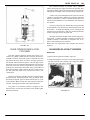
2. Place drain tube on the top end of the jack against the
bottom of windshield reinforcement with the outer screw
hole 1-3/8" from the outer end of the reinforcement.
3. Adjust the lower or telescoping end of the jack downward
with the wing nut until firm pressure is obtained against
the floor. This will hold the drain tube securely in position and leave both hands free for the succeeding operations.
4. Carefully punch two holes through the windshield reinforcement for the attaching Phillips screws (A), (No. 10 x
5/8" Binding He ad) using a punch guided by the screw
holes in the drain tube. This punch should be 1/8" in
diameter at the pin end, ground to a point as shown in
Figure 40, and have a length of 9" in order to project
under the instrument panel.
FIGURE 39
5. Secure d r a i n tube in place with self- tapping screws (A),
Figure 40, and remove jack.
1. Cement drain tube gasket securely to the inside "V" surface of
the drain tube, Figure 40. Spread a thin layer of trim sealer
NOTE: As a protective measure, wear safety goggles for
this operation.
INSTALLATION
6. Drill a 1/4" drain hole through the windshield reinforcement using drain tube as a template. Use care when doing
this to prevent damage to the windshield lower garnish
moulding.
7. Punch 11/32" hole through cowl side panel at point
shown in Figure 40, for lower end of drain hose. Enlarge
hole and insert hose so that it extends outside of the cowl
side panel.
8. Pack end of windshield reinforcement with only enough
dum dum, to seal the opening between the end of the
reinforcement and the garnish moulding.
CAUTION: Do not use an excessive amount of dum dum
because of the possibility of forcing the material over the
drain tube hole.
FIGURE 40
NOTE: If there is evidence of water leaking at the edge of
the windshield beyond the dum dum sealer, refer to the
article "Windshield Sealing".
23 BODY MANUAL
WINDSHIELD SEALING
(All Models Except 1C, 1D, 2C,
3D, 4D, 5D and 7D)
Minor leaks between the windshield rubber and the outside reveal moulding or between the outside reveal moulding and cowl or lower end of the roof panel on the 480
Models and early 490 Models up to and including Serial
No. 491-38746 (cars not equipped with windshield drains),
will result in water collecting in the windshield bottom
channel and dripping down along the cowl kick pads, or
dripping off of the under flange of the instrument panel
NOTE: A leak at the drip moulding will also be evidenced by wetness at the same places and should not be
confused with windshield leaks. To seal minor windshield
leaks, lay a bead of Dolphinite Sealer between the rubber
and outside reveal moulding and between the outside of the
reveal moulding and body panel. These beads of sealer must
be continuous around each rubber and/or reveal moulding.
Work the sealer into the joints and wipe off excess seale r
with cloth dampened with mineral spirits.
If it is necessary to remove the windshield glass to correct
the leak at the windshield, remove the windshield glass as
outlined on Page 20, and proceed as follows:
1. Clean windshield opening with a putty knife removing
all old sealer.
2. Remove the reveal moulding joint clip and remove the
reveal moulding.
FIGURE 41
NOTE: Locate the shims so that they will not interfere
with the installation of the lower retainers (G) and (H),
Figure 36, Page 20
.
5 After marking the location of the shims, remove the
windshield glass, weatherstrip and shims.
6. Caulk joint in lower outside face of windshield channel
at (J), Figure 42, with body sealer. Liberally apply body
sealer.
NOTE: If the reveal moulding has been removed, apply
windshield sealer in the pocket of t he reveal moulding
and press moulding firmly into place. Wipe off all excess
sealer from moulding and body finish.
NOTE: The welded flange joint (A), Figure 41, forming
the windshield opening must be straight throughout the
entire windshield area. A wavy area as shown at (B) must
be straightened t o ensure positive sealing between the
reveal moulding and the windshield flange joint and between the reveal moulding and windshield weatherstrip.
3. Remove all old sealer from the windshield glass rubber
weatherstrip. Install the rubber weatherstrip o n the windshield glass.
4. Install windshield glass and weatherstrip and shims as
required along bottom of windshield. Shim must be
placed so that inner edge of weatherstrip and glass is
parallel to the windshield center bar.
FIGURE 42
BODY MANUAL 24
7. Apply a heavy bead of windshield sealer completely
around windshield opening including the windshield
center bar. Sufficient sealer should be used around
the windshield weatherstrip when the windshield
and weatherstrip i s drawn into place . Figure 43,
shows cross-section (C-C) of the windshield opening
and the final sealer film after the windshield is installed. Sealer must be uniform.
8. Replace shims a s selected in operation No. 4. Apply
body sealer completely around shim but not on top
of shim, Figure 42.
FIGURE 44
12. Install the lower windshield finish moulding (F) entering under the center retainer and aligning with attaching screw holes. Install two screws.
13. Install upper windshield finish moulding (B) using
two long screws at top.
14. Install windshield center bar (D).
15. Tighten the lower finish moulding joint cover screw
and tighten antenna lower nut (C).
16. Install mirror (A).
17. Wipe off excess sealer on outside with cloth dampened with mineral spirits or gasoline.
18. Water test by applying a stream of water at moderate
pressure over the entire surface of the windshield and
front section of roof top.
FIGURE 43
9. Install glass and weatherstrip in windshield opening,
inserting outer end into windshield opening and
swinging inner edge into center bar.
10. Install one center lower windshield retainer (G),
Figure 44, to secure windshield in proper position.
11. In stall the remaining retainers. Apply soap stick to
the curved portion of the retainer that contacts the
windshield rubber weatherstrip. The retainer will then
slide down into position when tightened.
NOTE: Check defroster air blocks to be sure they are cemented securely in place. If necessary to install defroster air
blocks, see "Installation of Defroster Air Blocks", Page 24.
DEFROSTER AIR STOP BLOCKS
(Models 1948 and 1949)
INSTALLATION
1. Remove rear view mirror and bracket.
2. Remove upper right and left windshield finish moulding.
3. Remove windshield finish moulding lower joint cover
screw. (Note: On radio equipped cars, loosen nut
under instrument panel, retaining antenna to allow
finish moulding to be loose from joint cover.)
4. Remove right and left lower finish moulding.
25 BODY MANUAL
5. Remove existing air stop blocks from finish mouldings.
(Care must be taken in the removal of these blocks that
they remain in good condition for reassembly.
6. Join end blocks and rear block by cementing with rubber
cement at points (K) as shown in Figure 45, with the top
surface flush and the ends square.
FIGURE 46
INSTALLATION
NOTE: Apply a very light solution of liquid soap and
water to the weatherstrip to facilitate installation.
FIGURE 45
7. Apply coating of weatherstrip cement to under surf ace of
finish moulding in shaded area marked (H). Assemble
joined blocks to finish moulding, locating square and
flush to ends of defroster slot and tight to the bottom of
front flange.
8. Install right and left lower finish moulding.
9. Install joint cover and screw. (On radio equipped cars
tighten antenna nut and joint cover screw.)
10. Install upper right and left windshield finish mouldings.
11. Install rear view mirror bracket and mirror.
WINDSHIELD REVEAL
MOULDING
(Models 1C, 1D, 2C, 2D and 3D)
REMOVAL
1. Remove windshield wiper arms and blades.
2. Remove lower reveal moulding by pushing upward at
either corner to release moulding lip from groove in
weatherstrip, as shown in Figure 46.
3. Remove moulding joint cover by prying up with a screw
driver.
4. Push downward to release both upper mouldings from the
weatherstrip.
FIGURE 47
1. Install the upper right and left mouldings first by pressing
the lip of the mouldings into the lip joint of the weatherstrip, as shown in Figure 47.
2. Install the lower reveal moulding and moulding joint
cover.
NOTE: It may be necessary to use a rubber mallet to
facilitate the installation of the revea1 mouldings around
the corners of the windshield. Use mallet carefully to
avoid glass breakage.
3. Replace wiper arms and blades.
BODY MANUAL 26
WINDSHIELD REVEAL
MOULDING
(Models 4D, SD and 7D)
NOTE: To release the self locking type weatherstrip,
insert a screw driver into the split joint and work the
blade around the entire weatherstrip.
NOTE: For removal and installation, follow same procedure as outlined under "Windshield Reveal Moulding for
Models 1C, 1D, 2C, 2D and 3D", Page 25.
WINDSHIELD GLASS
(Models 1C, 1D, 2C, 2D and 3D)
REMOVAL
1. Remove windshield reveal mouldings. "See Windshield
Reveal Moulding Removal."
NOTE: Two types of weatherstrip are used interchangeably.
One type uses a separate locking strip installed in the weatherstrip to exert pressure against the glass and against the windshield opening pinchweld to form a positive seal. The other type
has a built in locking and sealing design which requires no expander. With either type the locking and sealing pressure has to
be released before removing the glass.
2. Remove weatherstrip expander by prying out one end and
then pull expander out of weatherstrip, as shown in Figure
48.
FIGURE 49
3. Remove the rear view mirror and the self tapping metal
screws attaching the garnish mouldings to the windshield
opening.
NOTE: To avoid breakage, a steady pressure should be
maintained at the top center of the glass by a helper while
the wedge is being worked to release the glass, Figure 49.
4. Using a tapered fibre or hardwood block, insert the end
of the wedge between the weatherstrip and the windshield glass; starting at the top of either corner and sliding
the wedge across the top releasing the glass from the
weatherstrip as shown in Figure 49.
5. When glass is completely released from the top of the
weatherstrip, lift glass out and away from body.
INSTALLATION
NOTE: With the weatherstrip properly in place over t he
windshield opening pinchweld brush the weatherstrip
thoroughly with a solution of liquid soap and water before installing the new glass, as shown in Figure 50.
FIGURE 48
1. With the aid of an assistant, insert the glass in the bottom
opening of the weatherstrip and using a tapered piece of
hardwood or fibre strip, start at the bottom of either side
of windshield and while lifting up lip of the weatherstrip
force the glass in place working the tapered block around
27 BODY MANUAL
FIGURE 50
the glass until the glass is completely enclosed in the weatherstrip channel, Figure 51.
FIGURE 52
WINDSHIELD GLASS
(Models 4D, 5D and 7D)
FIGURE 51
2. Insert the weatherstrip expander into the channel of the
weatherstrip starting at either lower corner and threading
the expander around the entire glass, using Tool J-2767,
Figure 52.
3. Pull both ends of expander together and trim off any
surplus to form a mitered joint.
NOTE: To lock the self-locking type weatherstrip, insert
the blade of a screw driver into the interlock opening in
weatherstrip and by exerting pressure downward, work
the screw driver around the weatherstrip.
4. Install windshield reveal mouldings, follow same procedure as
outlined under "Windshield Reveal Moulding Installation".
5. Position windshield garnish mouldings and rear view mirror, start
all screws before tightening.
NOTE: Care must be taken to install the proper length
moulding screws in order to avoid damage to the windshield glass or roof panel.
NOTE: For removal and installation, follow same procedure as outlined under "Windshield Glass" for Models
1C, 1D, 2C, 2D and 3D, Page 26.
REMOVAL
1. Remove windshield glass, follow same procedure a s
outlined under " Windshield Glass" for Models 10, 1D,
2C, 2D and 3D.
2. The weatherstrip is held in position over the pinchweld in
windshield opening by the compression action of the
groove in weatherstrip and can be removed by pulling
the weatherstrip away from the windshield opening.
INSTALLATION
1. With a tapered tool, open up the groove of the weatherstrip and press weatherstrip over windshield opening
pinchweld, Figure 53.
2. Reverse procedure of removal on balance of installation.
BODY MANUAL 28
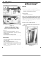
INSTALLATION
1. Use a stout piece of cord (Mason's chalk line) about
twelve inches longer than necessary to encircle one half
of the window. Lubricate the cord with paraffin or
beeswax.
2. Using a tapered fibre or hardwood wedge pry up the
outer lip of the rubber weatherstrip, Figure 54, and
place the cord under the weatherstrip lip starting at the
top center of the rear window and continuing around
one half of window to bottom center of rear window,
leaving sufficient cord at each end to provide a good
hold for pulling release cord, Figures 55 and 56.
FIGURE 53
WINDSHIELD WEATHERSTRIP
(Models 4D, 5D and 7D)
NOTE: For removal and installation, follow same procedure
as outlined under "Windshield Glass" for Models 1C, 1D,
2C, 2D and 3D, Page 27.
REAR WINDOW REVEAL
MOULDINGS
(All Models 1948 film 1954
Except 1C, 1D, 2C, 2D and 3D)
REMOVAL
1. Remove reveal moulding joint covers, top and bottom.
2. Insert a blunt screw driver under edge of reveal moulding and
pry moulding upward to release the moulding from the
rubber weatherstrip.
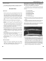
FIGURE 54
FIGURE 55
3. Place a joint cover on each end of the reveal moulding.
Fit the reveal moulding as close as possible to the contour of the rear window weatherstrip and retain the
moulding in it s approximate installed position by placing a piece of masking tape on the moulding to glass,
near both ends of the moulding, Figures 55 and 56.
FIGURE 56
29 BODY MANUAL
REAR WINDOW GLASS
(All Models 1948 thru 1954
Except 1C, 1D, .2C, 2D and 3D)
REMOVAL
1. Remove the rear seat cushion.
2. Cover the rear shelf and seat back with a protector cloth.
3. Place several thicknesses of masking tape to cover the
roof panel area around the rear window to prevent damage to the body finish when removing the window.
FIGURE 57
FIGURE 59
FIGURE 58
4. Have an assistant hold the moulding in place at the rear
window, Figures 57 and 58 and press the moulding
down and in toward glass while pulling the cord slowly
at right angles to the reveal moulding, this will release
and allow rubber lip of weather strip to enter into the reveal moulding recess.
NOTE: When pulling the cord from the weatherstrip apply firm finger pressure on the reveal moulding, following approximately two inches be hind the point where the
pull cord is releasing the weatherstrip lip.
5. After reveal mouldings have been properly positioned,
drift the moulding joint covers over the junction of the
two reveal mouldings.
4. One man should be inside the car to force the rear
window and weatherstrip outward, Figure 59.
5. Remove the complete window assembly from car to
bench.
6. Remove any broken glass fragments from weatherstrip
channel and remove all old sealer from the rear window
recess in the car body and also from the window retainer
weatherstrip recess.
7. Remove the window glass reveal mouldings from the
window weatherstrip. On the 502 and 504 models, also
remove the rear window center moulding retainer screws
and retainers. This will allow removal of the old glass.
INSTALLATION
NOTE: Apply a liquid soap (Do Not use lubricants containing mineral oil) to the window glass retaining recesses of the
weatherstrip to assist the installation of a new glass. No
sealer required in glass channel between glass and channel.
BODY MANUAL 30
FIGURE 63
FIGURE 60
1. Insert the new glass, working lips of weatherstrip recess
up over edge of glass until glass, is completely encased,
Figure 60.
FIGURE 61
NOTE: To facilitate assembly of the new glass on the 500
models, place a block of wood under the window center
bar, Figure 61.
FIGURE 62
2. After the window is installed in the weatherstrip channel
(500 series), tighten the center moulding retainer screws.
3. Carefully slide the reveal mouldings onto the weatherstrip.
4. Install moulding joint covers, Figure 62.
5. Apply a thin coat of rubber cement to the reveal
mouldings and 1-1/2" high on the glass completely
around the glass.
6. After rubber cement becomes tacky, place pieces of 2"
masking tape vertically and horizontally tying the
reveal mouldings and glass as a unit. Place strips 8"
apart, Figure 63. To further insure a good tight assembly, place a strip of masking tape completely encircling the window and reveal moulding.
7. Apply a ribbon of weatherstrip sealer to the body
recess channel in the weatherstrip. Allow only enough
sealer to fill the channel recess. (Use a thin piece of
wood approximately 3/4" wide to remove excess
sealer from the weatherstrip and also to force the
sealer into the weatherstrip recess.)
8. Tie a stout cord (Mason line) around the rear window
weatherstrip (between the inside body rubber lip and
lip of recess). Tie cord tightly enough to draw the
inner edges of the rubber c h a nn e 1 within the limits
of the body rear window opening. Tie cord at bottom
of window. Leave sufficient cord to provide a good
hand hold to pull the cord; tape loose ends to window
glass to prevent interference when installing the window assembly.
9. Place masking tape around the window recess at
inside of body to protect headlining, Figure 63.
10. Apply liquid soap on the inside of the large lip of the
weatherstrip and around the body recess lip.
11. With one man inside the car and one man on each
side of the car (outside), insert the window from the
outside, positioning glass evenly around window
opening with lower edge of weatherstrip over lip of
bottom flange in window opening.
31 BODY MANUAL
NOTE: The glass and weatherstrip assembly must be
positioned correctly as in paragraph 11, above, before
pulling the weatherstrip release strings; otherwise
weatherstrip lip will not seal properly.
INSTALLATION
NOTE: Apply a very light solution of liquid soap and water to
the weatherstrip to facilitate installation of the reveal mouldings.
12. With the two helpers firmly pressing inward and
downward on the glass and weatherstrip assembly and
with glass positioned properly in body recess, pull the
release cord slowly and carefully so that lip of weatherstrip is raised sufficiently to allow the window assembly to properly seat in the body recess.
13. Work the inner lip of the weatherstrip over the body
flange, using your fingers and applying additional
liquid soap as required.
NOTE: When performing the above operation the glass
must be forced into position by blows with a soft rubber
mallet or with the palm of the hand.
CAUTION: Do Not scratch the glass.
FIGURE 64
1. Install lower right and left reveal mouldings, by press in g lip of
moulding into groove in weatherstrip as shown in Figure 64.
14. After the glass and weatherstrip installation is complete, remove all excess sealer from the window weatherstrip and fabric on the inside of car with Hudson
Fabric Cleaner.
15. Remove all masking tape and protective coverings and
install rear seat cushion.
16. Remove all sealer from weatherstrip, glass, and body
finish with mineral spirits.
REAR WINDOW REVEAL
MOULDINGS
(Models 1C, 1D, 2C, 2D and 3D)
REMOVAL
1. Remove upper and lower reveal moulding joint covers
by prying up with a screw driver.
2. Remove the upper right and left reveal mouldings.
3. Remove the lower right and left reveal mouldings.
NOTE: When exerting pressure on the reveal mouldings to release the moulding lip from the groove in
weatherstrip, use care not to scratch the glass with the
moulding.
FIGURE 65
2. Install upper right and left reveal mouldings as shown in Figure
65.
3. Replace both reveal moulding joint covers.
NOTE: It may be necessary to use a rubber mallet to facilitate the
installation of the reveal mouldings around the corners of the rear
window. Use mallet carefully to avoid glass breakage.
BODY MANUAL 32
REAR WINDOW GLASS
(Models 1C, 1D, 2C, 2D and 3D)
REMOVAL
NOTE: Two types of rear window weatherstrips are used
interchangeably. One type uses a separate locking strip
which is inserted in the groove of the weatherstrip and
exerts pressure against the glass and the windshield opening pinchweld. The other type has a built-in locking and
sealing design which requires no expander. With either
type the locking and sealing pressure has to be released
before removing the glass.
1. Remove rear window reveal mouldings. See "Rear Window
Reveal Moulding removal."
2. Remove the weatherstrip expander by prying out one end
and then pull expander out of weatherstrip, Figure 66. To
release the self locking type weatherstrip, insert a screw
driver into the split joint and work the blade around the
entire weatherstrip.
FIGURE 67
3. With the aid of an assistant, start at the lower curved
section on each side of the glass and insert a tapered fibre
block between weatherstrip and behind the glass, as
shown in Figure 67. Work wedge across the bottom,
releasing glass from the weatherstrip. Grasp glass at
bottom and lift glass up and away from body.
INSTALLATION
NOTE: Before installing the new glass, brush the weatherstrip thoroughly with a solution of liquid soap and
water. Figure 68.
FIGURE 68
FIGURE 66
NOTE: Care must be taken when removing and installing
tempered glass. Do not scratch the surface, scratching may
cause the glass to disintegrate. The glass should not be hit
with any tool if breakage is to be avoided.
1. With the aid of an assistant, enter the glass into both side
openings of the weatherstrip and while pushing glass
upward, use a tapered fibre block to open the channel in
the weatherstrip to enter the glass, Figure 69.
2. After the glass has been entered at the top and sides of
weatherstrip, enter the tapered block between the weatherstrip and bottom of glass and carefully pull lip of weatherstrip channel over the glass until entire glass is seated in
the weatherstrip channel.
3. Insert the weatherstrip expander into the channel of the
33 BODY MANUAL
REAR WINDOW WEATHERSTRIP
(Models 1C, 1D, 2C, 2D and 3D)
REMOVAL
FIGURE 69
1. Remove rear window glass. See ''Rear Window Glass
Removal."
2. The weatherstrip is held in position over the pinchweld in
the windshield opening by the compression action of the
groove in the weatherstrip and ban be removed by pulling
the weatherstrip away from the windshield opening.
weatherstrip at either upper corner and thread the expander around the entire glass, using Tool J-2767, as
shown in Figure 70. Pull both ends of expander together
and trim off any surplus to form a mitered joint.
NOTE: To lock the self-locking type weatherstrip, insert
the blade of a screw driver into the interlock opening in
the weatherstrip and by exerting pressure downward,
work the screw driver around the weatherstrip, this procedure will interlock the weatherstrip.
4. Install rear window reveal mouldings, follow procedure
as outlined under "Rear Window Reveal Mouldings
Installation."
FIGURE 71
INSTALLATION
1. With a tapered fibre tool, open up the groove of the
weatherstrip and press weatherstrip over the rear window opening pinchweld, Figure 71.
2. Reverse procedure on balance of installation.
QUARTER TRIM PANEL
BROUGHAMS AND COUPES
(All Models 1948 thru 1954
Except 1C, 1D, 2C, 2D and 3D)
REMOVAL
FIGURE 70
1. Remove rear seat cushion and rear seat back.
2. Remove quarter window regulator handle.
3. Remove garnish moulding.
BODY MANUAL 34
4. On Commodore models remove valance.
5. Remove two screws from under side of arm rest and
remove arm rest.
6. Remove pocket trim panel and lower trim panel, attached
by clips to inner panel.
INSTALLATION
Reverse procedure of removal.
QUARTER WINDOW WATER
SHED AND DRAIN BAFFLE
(Models 1948 and 1949)
INSTALLATION
NOTE: If there is evidence of a water leak at the area
around the rear seat and it has been
d et e r min e d that the door seals and drain troughs have
been properly sealed, check the sealer at the drain baffle
located below the rear quarter window at the top of the
body frame rail and seal along the bas e of the baffle applying body sealer in the areas shown in Figure 72.
To install the water shed and drain baffle on the 480
models and the early 490 models broughams and coupes,
proceed as follows:
1. Remove the rear seat cushion and back.
2. Remove the qua r t e r window garnish moulding.
3. Remove the garnish moulding wood filler strip.
4. Re move the glass run (K), Figure 72. (With window
down, pull top of channel inward and upward to remove.)
5. Remove the rear quarter glass (0). (Guide t op of glass i n
w a r d and turn up until regulator arms are above inner
panel. Disengage regulator arm roller (L) from glass and
channel as an assembly.)
6. Remove the regulator handle. (Concealed pin.)
7. Remove the arm rest - (two screws).
8. Remove the quarter pocket trim panel.
9. Remove the quarter lower trim panel.
10. Remove the quarter inner panel liner.
11. Remove the regulator screws (A), (B),
(C), (D) and (E).
12. Remove the regulator guide channel screws (E) and (F).
13. Remove the glass run channels (M), (N), screws (G), (H),
(I) and (I)
FIGURE 72
14. Bend straight edge of water shed outward along scored
line.
15. Insert rear end of watershed below inner panel and work
upward and backward into position shown. Be sure
forward edge is t u r n e d outward and hold watershed
in position to top of inner panel with a clamp.
16. Install regulator and regulator guide channel (L).
17. Install glass run channels (M), (N) and (K).
18. Install glass and glass run.
19. Put pillar to wheelhouse baffle (P) in place on top of
frame and mark drilling 1 o c at i on at each end. Drill
two 7/32" holes in baffle at (Q).
20. Mark wheelhouse flange and pillar inner flange and drill
a #29 (.136") in each.
21. Attach baffle with two No. 10 by 3/4" binding head
sheet metal screws.
22. Seal baffle full length on both outside and in side with
body sealer. Apply rubber cement to the inner side of the
rocker panel to frame seal and insert the seal between
frame and rocker panel pressing tight against front end of
rear fender to frame seal, both right and left hand side.
35 BODY MANUAL
QUARTER WINDOW REGULATOR
BROUGHAMS AND COUPES
(All Models 1948 thru 1954
Except 1C, 1D, 2C, 2D and 3D)
REMOVAL
1. Remove quarter trim panel. See page 33.
2. Remove quarter panel inner liner.
3. Remove quarter window glass.
4. Remove four Phillips head screws attaching regulator to
inner panel and remove regulator through lower opening in
inner panel.
INSTALLATION
Reverse procedure of removal.
QUARTER WINDOW GLASS
BROUGHAMS AND COUPES
(All Models 1948 thru 1954
Except 1C, 1D, 2C, 2D and 3D)
REMOVAL
1. Remove garnish moulding and small wood block.
2. Lower window and release three clips attaching glass run
channel to top of window opening by pulling in on channel.
3. Remove glass run channel.
4. Pull in on top of glass and raise glass to limit of regulator.
5. Release regulator from glass channel and remove glass and
channel.
INSTALLATION
1. Pull in on top of inner panel to enlarge opening between
inner and outer panels.
2. Insert glass and glass channel through opening and engage
regulator.
3. Lower the window and apply a coating of cement to
window opening to seal glass run channel.
4. Insert glass run channel and engage clips in top of window
opening.
5. Raise window and replace wood block and garnish moulding.
QUARTER WINDOW GLASS
BUSINESS COUPES
(All Models 1948 thru 1954
Except 1C, 1D, 2C, 2D and 3D)
REMOVAL
1. Remove garnish moulding.
2. Remove small wood block.
3. Remove two screws holding window support to inner
panel. Hold window in position and remove support.
4. Lower glass to free it from glass run channel and lift out.
INSTALLATION
Reverse procedure of removal.
QUARTER WINDOW GLASS
SEDANS (PIVOT TYPE)
(All Models 1948 thru 1954
Except 1C, 2C, 1D, 2D and 3D)
REMOVAL
1. Remove garnish moulding.
2. Remove f our sheet metal screws attaching glass frame
to window opening and remove glass and frame.
3. Remove nut and spring from friction pivot.
4. Remove screw from upper pivot and remove window
and frame.
INSTALLATION
Reverse procedure of removal.
QUARTER WINDOW GLASS
SEDANS (PIVOT TYPE)
(All Models 1948 thru 1954
Except 1C, 2C, 1D, 2D and 3D)
REMOVAL
1. Remove the three sheet metal screws attaching garnish
moulding to window opening.
2. Push glass inward and remove glass, weatherstrip and
frame.
BODY MANUAL 36
INSTALLATION
INSTALLATION
Reverse procedure of removal.
Reverse procedure of removal.
QUARTER WINDOW GLASS
(Models 1C, 1D, 2C, 2D and 3D)
QUARTER WINDOW REGULATOR
(Models 1C, 1D, 2C, 2D and 3D)
REMOVAL
REMOVAL
1. Remove rear seat cushion and back.
1. Remove rear seat cushion and back.
2. Remove garnish moulding and regulator handle.
3. Remove quarter trim panel.
4. Lower quarter glass and remove the two retaining clips
from the regulator arm and disconnect arm from glass channel.
5. Cut inner liner to expose the four regulator attaching
screws and remove screws.
6. Remove regulator through lower opening in inner panel.
2. Remove garnish moulding and regulator handle.
3. Remove quarter trim panel.
4. With quarter glass in the down position remove the two
retaining clips from the regulator arm.
5. Remove regulator arm from glass channel.
6. Raise the quarter glass, tilt glass inward and remove
through top opening in quarter panel.
INSTALLATION
Reverse procedure of removal and repair any damage to
panel inner liner.
REFERENCES
Source of
Information
Date
Subject
37 BODY MANUAL
HEADLINING
(All Models 1948 thru 1954
Except Hollywood Models
and 1C, 1D, 2C, 2D and 3D)
Preparatory to headlining removal, remove the following
trim parts:
A. Sun visors
B. Rear view mirror
C. Front dome lamp lens assembly
D. Upper and lower windshield garnish moulding
E. Windshield inside center trim bar (on cars so
equipped)
F. Rear seat cushion, seat back and center arm rest
G. Rear window (see Rear Window Removal), Page 29.
H. Rear package shelf
I. Rear quarter window garnish mouldings
J. Rear dome lamp lens assembly
REMOVAL
1. Remove tacks from around rear window opening and rear
quarter window openings and the cardboard tacking strips
at the extreme rear edge of the headlining on the package shelf.
Pull headlining loose from cement.
2. Remove headlining from glazier's points around upper windshield opening. Use a screw driver to pry open these glazier's
points to facilitate installation of n e w headlining.
3. With a sharp knife slit the headlining on both sides, front to rear,
along the side retainers; remove roof bows from rubber
grommets and remove headlining from body.
4. Loosen screws in the headlining side retainers and remove old
headlining and glue from glazier's points. Retighten
screws securely.
5. Remove all old cement from around rear window and rear
quarter window openings. Apply new cement to these areas and
allow it to become tacky before beginning the installation.
INSTALLATION
NOTE: Before removing roof bows from old headlining,
properly mark or tag each bow to insure correct placement of
the roof bows in the headlining as this is important.
1. After checking to make certain that the roof bows
have been installed in their proper sequence in the
new headlining, start the installation into the body
with the rear bow. (Leave the first two hanging
loosely in their grommets. Do not snap up into the
support brackets. This prevents undo stretching of the
material at this point) . Work progressively toward
the front, installing each roof bow into its rubber
grommet and support bracket leaving the front bow
hanging loosely in the rubber grommets.
2. Move to the rear of the body and snap the two rear
roof bows into the support brackets. Press headlining
temporarily into the cement at the top center of the
rear window opening. (This holds the headlining out
of the way for installation of the cardboard tacking
strips.) Pull headlining down evenly at cardboard
tacking strips on both sides and tack the strips securely at the rear package shelf.
3. Pull headlining tight and press into cement around
rear window opening. Trim the material at the corners of the opening to assure a smooth fit and prevent
pleating. Replace upholsterer's tacks in rear window
opening. Trim surplus material from around rear
window opening. Cut a separate piece of headlining
material wide enough and long enough, and install
into c e me n t at bottom edge of rear window opening. Tuck material under the edges of the headlining
and secure with upholsterer's tacks. (This separate
piece of material covers the panel between the lower
edge of the rear window and the package shelf.)
Material should be wide enough to extend to the
package shelf and be held in place by the rear package
shelf trim boards.
4. Cut the headlining material at the corners of the rear
quarter windows and press firmly into the cement.
Secure with upholsterer' s tacks.
5. Re-install rear package shelf trim board. Cement and
tack into place at the front edge.
6. Now move to the front of the body and snap the front
roof bow into the support brackets . Stretch the headlining forward and, beginning at the center of the
windshield opening, attach headlining to glazier's
points in the upper windshield opening. After the
headlining is securely hooked on the glazier's points,
hammer the points flush with the windshield opening.
BODY MANUAL
38
(This assures perfect fit of windshield sealing strip and
prevents leaks at this point.) Trim away surplus material.
7. Next, using Tool J-2772, carefully tuck the edges of the
headlining up under the side retainers. (Before starting
this operation check to be sure that the side retainers are
fastened securely.) Use the tool carefully in this operation.
Start at the front and we toward the rear, stretching the
headlining as the work progresses.
8. Carefully slit the headlining at the dome lights and install
the dome light lens assemblies.
NOTE: Trim away only enough material at the dome lights to
clear the bulb recess in the lamp base. Headlining is held in
place at this point by the dome lamp lens assembly; therefore
do not trim away more material than is absolutely necessary.
9. Re-install rear window and all trim parts removed prior to
headlining removal operations.
HEADLINING
(Models 1C, 1D, 2C, 2D and 3D)
REMOVAL
1. Remove the sun visors, the antenna knob and knob escutcheons, the rear view mirror, the right and left windshield garnish mouldings, the dome lamp glass and bezel
assemblies (snap-in type).
2. Remove the rear seat cushion and rear seat back.
3. Remove the rear window glass and weatherstrip, as outlined in "Rear Window Removal and Installation", Page
32.
4. Remove the upholsterer's tacks from around the rear
window opening as shown in Figures 73 and 75, pull
headlining loose from cement.
5. Remove headlining from glazier's points at upper windshield opening and pull headlining from cement.
6. Use a screw driver to pry open these glazier's points to
facilitate installation of a new headlining. Remove headlining from retainers at front pillar posts.
7. Use a narrow blade putty knife and working through the
opening between the windlace panel and roof header
FIGURE 73
unhook the headlining cloth from the glazier's points until
complete headlining is removed or as required.
NOTE: If the complete headlining is to be removed and
replaced with a new headlining, slit the headlining along
the retainers on both sides of body, snap out roof bows
and remove headlining. Loosen retainer screws and remove the scrap material from the glazier's points. Retighten retainer screws securely.
FIGURE 74
39 BODY MANUAL
NOTE: Before replacing headlining make sure roof panel
insulation is securely glued and in the proper position and
the retainer strips are aligned as shown in Figure 74.
INSTALLATION
1. Apply trim cement at flange of rear window opening and
at windshield opening. Allow cement to become tacky
before installing new headlining.
NOTE: Remove roof bows from the old headlining and
install them in the new headlining. The correct placement
of the roof bows in the headlining i s very important. The
following roof bow color guide will assist you to place the
bows in their proper sequence. One end of the bow is
painted as follows:
No. 1 Roof Bow - White
No. 2 Roof Bow - Light Green
No. 3 Roof Bow - Yellow
No. 4 Roof Bow - Light Red
No. 5 Roof Bow - Dark Blue
No. 6 Roof Bow - Dark Brown
2. Starting at the rear of body roof panel, hook in each end of
the roof bow into the roof bow anchor bracket and snap
into position.
3. Install the remaining bows in their proper sequence, spacing the headlining evenly between each bow.
FIGURE 76
NOTE: The first seam at rear of headlining should be
approximately six inches from inside edge of roof panel to
rear window flange as shown in Figure 76.
5. Stretch headlining and force it under the metal retaining
strip, using Tool J-2772, starting at the rear on both sides
and working to the front. Keep seams straight from side
to side.
6. Snap front roof bow in position, stretching the headlining
Over the windshield header glazier's points and cement
headlining to the inside flange of windshield, as shown
in Figure 77.
NOTE: Hook number one bow in the roof bow bracket, but
do not snap into position at this time.
4. Stretch headlining down and press into cement around rear
window opening. To avoid wrinkles and pleats in the
material at corners, cut several radial slits about 1-1/2"
apart and 3/4" deep. Work material around the flange of
the rear window opening and tack in place with upholsterer's tacks, Figure 75.
FIGURE 77
FIGURE 75
7. With windcord in position at front pillar posts, securely
hook headlining to t he glazier's points.
8. Install windshield garnish mouldings, see "Garnish
Moulding Installations", rear view mirror, sun visors
and antenna knob and escutcheon.
9. Carefully cut the headlining at the dome light and install
the dome light lens and bezel assemblies.
10. Install the rear window weatherstrip and glass. See "Rear
Window Installation", Page 32.
MODELS 1948-1949
FIGURE 78
BODY MANUAL
40
MODELS 1950
FIGURE 79
41 BODY MANUAL
MODELS 1951
FIGURE 80
BODY MANUAL
42
MODELS 1952
FIGURE 81
43 BODY MANUAL
MODELS 1953 EXCEPT 1C AND 2C
FIGURE 82
BODY MANUAL
44
MODELS 1953-1954 1C. 1D, 2C, 2D AND 3D
FIGURE 83
45 BODY MANUAL
MODELS 1954 4D, 5D AND 7D
FIGURE 83
BODY MANUAL
46
47 BODY MANUAL
INSTRUMENT CLUSTER
AND PANEL ASSEMBLY
INSTRUMENT CLUSTER
AND PANEL ASSEMBLY
(All Models 1948 thru 1950)
(Models 1C, 1D, 2C, 2D and 3D)
REMOVAL
1. Remove ornamental trim.
2. Remove locker box and glove compartment door bumpers.
3. Remove two screws from each end of finish panel. Screws are
exposed when glove compartment and locker box doors are
open. On models not equipped with locker box (left side) remove
screw from inside upper edge of left section of finish panel to
release hinged panel and expose screws. On earlier models three
screws hold this section of the panel in place.
NOTE: On radio equipped cars it is necessary to remove
control knobs and escutcheon nuts.
INSTALLATION
Reverse procedure of removal.
INSTRUMENT CLUSTER
AND PANEL ASSEMBLY
(All Models 1951 thru 1953
Except 1C, 2C)
REMOVAL
1. Disconnect the negative battery cable from the battery.
2. With cars equipped with Weather Control, remove both
control knobs from the heater control assembly and remove the fuse from the lead wire.
3. Remove the two bolts attaching the hand brake support
bracket to the instrument panel which also attaches the
heater control assembly to the instrument panel and
remove the one screw at the opposite side of control.
4. Re move the heater control assembly and carefully place
to one side - (leave all control cables attached).
5. Remove the ignition switch assembly from the instrument panel, (leave all wires attached).
6. Disconnect speedometer cable at speedometer.
7. Using a six inch extension on a 1/4" ratchet set, remove
the six 3/8" nuts from the studs attaching the instrument
cluster assembly to the instrument panel.
8. Pull the instrument cluster assembly forward sufficiently
to expose the back face of the cluster assembly to allow
removal of speedometer head, fuel and temperature
gauge and constant voltage regulator.
REMOVAL
INSTALLATION
1. Remove two nuts and washers attaching top of cluster to
instrument finish panel (3/8" socket).
2. Remove two nuts and washers one at each side attaching
cluster to finish panel using a 3/8" socket with a ferret
handle and 6" extension.
3. Remove one nut and washer located directly above steering column tube using a 3/8" socket with a ferret handle
and 6" extension.
4. Push instrument panel from rear sufficiently to allow disconnecting of the speedometer cable from speedometer head and pull the
panel forward and remove the speedometer head, clock, fuel
gauge and temperature gauge, headlight switch and windshield
wiper control assembly.
To install, reverse procedure of removal.
INSTALLATION
To install, reverse procedure of removal.
INSTRUMENT CLUSTER
AND PANEL ASSEMBLY
(Models 4D, 5D and 7D)
REMOVAL
1. Disconnect the negative battery cable from the battery.
2. Disconnect speedometer c able at speedometer.
3. Using a six inch extension on a 1/4" ratchet set, remove
the eight 3/8" nuts from the studs attaching the instrument cluster assembly to the instrument panel.
BODY MANUAL
4. Pull the instrument cluster assembly forward sufficiently
to expose the back face of the cluster assembly to allow
removal of speedometer head, clock, fuel and temperature
gauge and constant voltage regulator.
INSTALLATION
To install, reverse procedure of removal.
SPEEDOMETER HEAD
(All Models 1948 thru 1950)
48
SPEEDOMETER HEAD (Models 4D,
5D and 7D)
REMOVAL
1. Remove instrument cluster and panel assembly. See
"Instrument Cluster and Panel Assembly Removal".
2. Snap out speedometer bulb and socket assemblies.
3. Remove the four screws attaching speedometer to instrument
cluster panel and remove speedometer.
INSTALLATION
REMOVAL
To install, reverse procedure of removal.
1. Remove instrument cluster and panel assembly. See
"Instrument Cluster and panel Removal".
2. Remove four screws attaching speedometer to instrument panel and remove speedometer from panel.
3. Pull the beam indicator and instrument lamps and sockets from the speedometer and unscrew the cable.
REMOVAL
INSTALLATION
1. Remove the instrument cluster assembly, follow operations 1
Reverse procedure of removal.
SPEEDOMETER HEAD
(All Models 1951 thru 1953
Except 1C, 2C)
REMOVAL
1. Snap out bulb and socket assembly.
2. Disconnect speedometer cable at speedometer head.
3. Remove four Phillips head machine screws and remove
speedometer head as an assembly.
NOTE: If more than one instrument has to be removed at one
time, it is more practical to remove the five screws attaching
the instrument cluster and panel assembly and pull the panel
forward sufficiently to expose the back f ace of the panel. See
"Instrument Cluster and Panel Removal".
INSTALLATION
To install, reverse procedure of removal.
SPEEDOMETER HEAD
(All Models 1C, 1D, -2C 2D and 3D)
through 8 under "Instrument Cluster and Panel Assembly
Removal".
2. Snap out speedometer bulb and socket assemblies and disconnect wire for high beam signal light.
3. Remove four screws attaching speedometer to instrument cluster panel and one small Phillips head screw attaching speedometer head to speedometer bezel and remove the
speedometer.
NOTE: It is also necessary to perform the preceeding operations to replace the speedometer lens or the headlight high
beam signal bulb.
CLOCK
(All Models 1948 thru 1950)
REMOVAL
1. Remove instrument cluster and panel assembly. See
"Instrument Cluster and Panel Removal".
2. Remove four screws attaching clock to instrument panel and
remove clock from panel.
3. Pull the instrument lamp and socket from the clock.
49 BODY MANUAL
FUEL GAUGE
(All Models 1950)
4. On electric clocks, disconnect feed wire at fuse connector.
INSTALLATION
Reverse procedure of removal.
CLOCK
(All Models 1951 thru 1953)
1. Remove the two screws attaching the gauge cluster to
the instrument panel and remove the gauge cluster.
2. Remove fuel gauge unit.
INSTALLATION
Reverse procedure of removal.
REMOVAL
1. Snap out bulb and socket assembly.
2. Remove four Phillips head machine screws attaching clock to
instrument cluster and remove clock assembly.
NOTE: On cars equipped with radio, the clock can be reached
by removing the radio speaker and grille and work through grille
opening.
INSTALLATION
To install, reverse procedure of removal.
CLOCK
(Models 4D, 5D and 7D)
REMOVAL
1. Remove instrument and cluster and panel assembly. See
"Instrument Cluster and Panel Assembly Removal".
2. Remove four screws attaching clock to instrument cluster panel.
3. On electric clocks, disconnect feed wire at fuse connector and
remove clock.
INSTALLATION
Reverse procedure of removal.
FUEL GAUGE
(All Models 1948 thru 1949)
FUEL GAUGE
(All Models 1951 thru 1953
Except 1C, 2C)
REMOVAL
1. Remove the two screws attaching the gauge cluster to the
instrument panel.
2. Remove fuel gauge unit.
NOTE: To facilitate checking and testing gauge and
regulator operation, remove the five nuts and washers
attaching the instrument cluster to finish panel and pull
panel forward, exposing the back face of the cluster and
panel assembly. (See "Instrument Cluster and Panel Assembly Removal".)
INSTALLATION
Reverse procedure of removal.
FUEL GAUGE
(All Models 1C, 1D, 2C, 2D and
3D)
REMOVAL
REMOVAL
1. Remove instrument finish panel.
2. Remove four screws attaching cluster to instrument panel.
3. Remove two screws from base of gauge
and disconnect wires and remove gauge.
1. Follow same procedure as for the "Instrument Cluster
and Panel Assembly Removal"
2. Remove the two screws attaching the fuel gauge to the
instrument cluster assembly, disconnect wires and remove the fuel gauge.
INSTALLATION
Reverse procedure of removal.
INSTALLATION
To install, reverse procedure of removal.
BODY MANUAL
FUEL GAUGE
(Models 4D, 5D and 7D)
REMOVAL
1. Remove instrument cluster and panel assembly. See
"Instrument Cluster and Panel Removal".
2. Remove the four screws attaching gauge cluster to instrument cluster panel, disconnect wires and remove fuel
gauge unit.
INSTALLATION
Reverse procedure of removal.
TEMPERATURE GAUGE
(All Models 1948 thru 1949)
1. Follow same procedure as for "Fuel Gauge
Removal" and "Installation", Page 49.
TEMPERATURE GAUGE
(All Models 1950)
1. Follow same procedure as for "Fuel Gauge
Removal" and "Installation", Page 49.
TEMPERATURE GAUGE
(All Models 1951 thru 1953
Except 1C, 2C)
1. Follow same procedure as for "Fuel Gauge
Removal" and "Installation", Page 49.
TEMPERATURE GAUGE
(All Models 1C, 1D, 2C, 2D and 3D)
1. Follow same procedure as for "Fuel Gauge
Removal" and "Installation", Page 49.
TEMPERATURE GAUGE
(Models 4D, 5D and 7D)
1. Follow same procedure as outlined under "Fuel Gauge
Removal" and "Installation", Page 50.
50
CONSTANT VOLTAGE
REGULATOR
(All Models 1951 thru 1953)
1. Follow same procedure as outlined under "Fuel Gauge
Removal" and "Installation", Page 49.
CONSTANT VOLTAGE
REGULATOR
(All Models 1C, 1D, 2C, 2D and 3D)
1. Follow same procedure as for "Fuel Gauge
Removal" and "Installation", Page 49.
CONSTANT VOLTAGE
REGULATOR
(Models 4D, 5D and .7D)
1. Follow same procedure as for "Fuel Gauge
Removal" and "Installation", Page 50.
FUEL GAUGE CHECK
(All Models 1948 thru 1950)
If the fuel level gauge becomes inoperative, it is recommended that an extra tank unit be used for testing. If there
is any question about the tank test unit being correct, then
hook it up in series with a receiver known to be correct and
6 volts of battery current. Operate the tank unit by hand and
see if the receiver reads "Zero" with tank unit float in bottom
position and "Full" with tank unit float in the top position.
Use two ten-foot lengths of insulated wire equipped with
clip terminals at each end. These lengths will permit checking by one person in front of the dash unit.
Do not remove either the dash or tank unit from the
automobile until the elimination tests outlined below prove
them in need of replacement.
1. Disconnect the lead of the tank unit on the car and
connect this lead to the tank test unit and ground same to
the car frame. Turn on ignition switch and operate tank
test unit float by hand. With the float of the test unit at the
bottom position the car dash unit should register at the
bottom mark on the dial as in Figure 85. Move float rod
up to top position and car dash unit should move to top
mark on the dial, as shown in Figure 86. Allow one minute
51 BODY MANUAL
for dash unit pointer to come to rest.
CAUTION: Do not attempt the repair or calibration of
any dash unit or tank unit.
TEMPERATURE GAUGE CHECK
(All Models 1948 thru 1950)
1. It is impossible to adjust or repair either unit of the temperature
gauge.
2. The method of elimination testing to determine which unit is
faulty is basically the same as for the fuel gauge except that the
test sending unit in this case be installed in the cylinder head when
making the tests.
FIGURE 85
CONSTANT VOLTAGE
REGULATOR, FUEL AND
TEMPERATURE GAUGE
(All Models 1951 thru 1954)
Method of Checking
VOLTAGE REGULATOR CHECK
The constant voltage regulator is common to both the fuel and
temperature system, in that one regulator is used to operate both
systems, Figure 87.
FIGURE 86
a. The tank unit is grounded through the case. Check the
ground connections. See that paint and grease are removed under the flange and that surfaces are making good
contact.
b. If the car is radio equipped, check the condenser on the
tank unit. If the condenser is shorted, it will cause the dash
unit to over-read. When replacing condenser it is preferable to use one of the .10 micro-farad capacity but up to .50
can be used to cut out radio interference.
c. If the ground (see paragraph a) and condenser (see
paragraph b) are correct then replace the tank unit.
2. If the dash unit does not operate, or fails to operate
correctly, then check the wire lead to the dash unit and
replace the wire if faulty.
3. If the wiring is satisfactory, then replace the car dash unit
and check it with the tank unit on the car. If the dash unit
now fails to operate when connected to car tank unit,
install a new tank unit.
FIGURE 87
1. If both gauges read too high, for example, if the gas gauge reads
up the scale with an empty gas tank and the temperature gauge
reads up the scale with a cold engine, the constant voltage regulator is not working properly and should be replaced; (check
ground connections of the voltage regulator, as grounding is
BODY MANUAL
essential to the proper functioning of the regulator).
2. If both gauges read too low, either the input voltage to
constant voltage regulator is below 5.0 volts or the voltage
regulator is inoperative and should be replaced. Check
battery voltage output before replacing regulator.
FUEL GAUGE CHECK
1. Disconnect lead wire at gas tank unit.
2. Hook in a new tank unit of proper calibration. See Figure
87. Place float in empty position. Turn on ignition switch.
Panel gauge should read at (E) on dial.
3. Move float to full position, panel gauge should read full
(F).
NOTE: If check 2 and 3 are O.K., both panel gauge and
lead wire are O.K. If checks 2 and 3 are not O.K., hook up
a new tank unit to proper terminal of panel gauge and
eliminate the lead wire from the panel indicator to the unit
from the regulator circuit. Repeat empty and full check. If
now operating O.K., correct or replace defective wire
between tank unit and panel gauge.
TANK UNIT CHECK
If there is any question about the tank level unit being
O.K., hook the tank unit up in series with a panel indicator
and a constant voltage regulator known to be O.K. and a six
volt battery. Operate tank level unit by hand and see if panel
indicator reads empty (E) with tank level unit float in bottom
position and reads full with level unit float in top position. If
the panel indicator and lead wire function properly with a
new O.K. tank unit, but did not function properly with
original unit, replace original unit.
NOTE: Be sure tank unit is properly grounded to gas tank
and also that the tank is grounded to the frame.
TEMPERATURE GAUGE CHECK
1. If the temperature gauge reads up scale with a cold engine,
and the gas gauge reads up scale with an empty gas tank,
the constant voltage regulator is not operating properly
and should be replaced. (Check ground connections of the
voltage regulator as grounding is essential to the proper
functioning of the regulator.)
52
2. If both gauges read too low, either the input voltage to the
constant voltage regulator is below 5.0 volts or the voltage
regulator is inoperative and should be replaced. Check battery
voltage output before replacing regulator.
3. To check cylinder block sender unit proceed as follows:
a. Submerge unit in water up to the hexagon shoulder.
b. Attach "Ohm" meter to terminal. c. With water temperature at 160 F°, resistance must be 25.8-30.8 Ohms.
NOTE: It is not advisable to attempt any repairs or adjustments to either unit of the gauge since they are factory calibrated and any attempt to repair is impractical.
WINDSHIELD WIPER CONTROL
(All Models 1948 thru 1954)
REMOVAL
1. Loosen screw attaching control wire to wiper motor and
remove wire from motor.
2. Loosen set screw in control knob and remove knob.
3. Using a suitable spanner, remove escutcheon nut and escutcheon.
4. Remove wiper control from panel and pull control wire
through dash.
INSTALLATION
Reverse procedure of removal.
LIGHT SWITCH AND CIRCUIT
BREAKER ASSEMBLY
(All Models 1948 thru 1954)
REMOVAL
1. Disconnect negative battery cable at battery.
2. Loosen set screw in control knob and remove knob.
3. Using a suitable spanner, remove escutcheon nut and escutcheon.
4. Remove switch and remove wires from switch.
INSTALLATION
Reverse procedure of removal. Keep battery disconnected until
operation is completed.
53 BODY MANUAL
STARTER SWITCH
(All Models 1948 thru 1951)
REMOVAL
1. Turn ignition switch to "Off" position.
2. Remove Phillips head screw from the under side of instrument
panel.
3. Remove switch and disconnect wires.
INSTALLATION
Reverse procedure of removal.
IGNITION SWITCH
(All Models 1948 thru 1951)
REMOVAL
1. Disconnect negative battery cable at the battery to prevent
accidental short circuits.
2. Remove Phillips head screw from underside of instrument
panel, and remove switch.
3. Remove wires from switch terminals.
INSTALLATION
Reverse procedure of removal. Keep battery disconnected
until operation is completed.
STARTER-IGNITION SWITCH
(All Models 1952 thru 1954)
WEATHER CONTROL BLOWER
SWITCH
(All Models 1951 thru 1954
Except 1C, 1D, 2C, 2D and 3D)
REMOVAL
1. Loosen Allen set screw in control knob
and remove knob.
2. Remove escutcheon nut and pull switch through mounting
panel.
3. Remove wire from switch.
INSTALLATION
To install, reverse procedure of removal.
WEATHER CONTROL LEVER
AND BRACKET ASSEMBLY
(All Models 1951 thru 1954
Except 1C, 1D, 2C, 2D and 3D)
REMOVAL
1. Remove the screw attaching the weather control lever knob to
the control lever.
2. Remove two screws attaching control bracket to instrument
mounting bracket.
3. Remove the sheet metal screw and clamp, and disconnect the
Bowden wire at the lever pin and remove the control bracket
and lever as an assembly.
INSTALLATION
REMOVAL
To install, reverse procedure of removal.
1. Disconnect negative battery cable from battery.
2. Remove Phillips head screw from underside of instrument
panel.
WEATHER CONTROL ASSEMBLY
(All Models 1C, 1D, 2C, 2D and 3D)
NOTE: On Models 4D, 5D and 7D remove the chrome
Phillips head screw on face of instrument panel.
3. Remove switch and disconnect wires.
INSTALLATION
Reverse procedure of removal.
1. Remove both heater control knobs from heater control assembly.
2. Remove the fuse from the lead wire.
3. Remove the two bolts attaching the hand brake bracket to
the instrument panel which also attaches the heater control
assembly and one screw at the opposite side of the control
assembly.
4. Remove the sheet metal screws and clamps and disconnect
all Bowden wires and remove the assembly.
BODY MANUAL
NOTE: It is advisable to perform operations (1)-(2) and (3) when
replacing Weather Control Blower Switch.
INSTALLATION
Reverse procedure of removal.
INSTRUMENT PANEL TOP
COVERING
(All Models 1951 thru 1954)
REMOVAL
1. Remove the rear view mirror.
2. Remove windshield garnish mouldings.
3. Remove radio speaker grille.
4. On Models IC, 1D, 2C, 2D and 3D remove radio and locker box.
5. From behind the instrument panel at the top loosen the five nuts
sufficiently (do not remove) to allow instrument finish panel to be
pulled forward to remove the panel top covering.
6. Remove the two side screws attaching the instrument finish panel
to the, instrument panel.
7. Pull covering loose by working from windshield towards instrument finish panel.
54
INSTALLATION
1. Clean top of instrument panel thoroughly to insure an
even surface.
2. Apply a light coat of trim cement direct to the covering.
3. Carefully install the covering to the instrument panel allowing
1/2" of fabric to overlap the instrument panel at finish panel.
Where the five studs attached to the instrument finish panel
enter into the instrument support panel, cut 1/4" slots in the
covering to allow the material to go between the instrument
finish panel and the instrument panel. With a blunt putty
knife, start from center and work towards both ends of instrument panel. Trim a round end corners and tuck ends in at
each end of instrument panel. Work from instrument finish
panel towards grille and windshield working out all bumps
and wrinkles in fabric.
NOTE: Do not cover defroster outlets at windshield; cut
and trim as required for radio speaker and defroster outlets.
4. Install garnish mouldings, rear view mirror, radio
speaker grille.
5. Replace the two side instrument finish panel screws and
retighten the five nuts behind the instrument panel.
FIGURE 88
55 BODY MANUAL
(Models 1948 thru 1950)
the burred bushings by a spring clip which is released by
pulling the arm up and away from the windshield.
3. Remove the bolt and clamp from the underside of the
cowl panel.
The windshield wiper mechanism consists of a vacuum operated
motor assembly, two spring loaded cable tension assemblies, two
pulley housing and cable assemblies, wiper arms, blades, and cables.
NOTE: To remove right hand assembly, glove compartment must be removed to gain access to this bolt and
clamp.
WINDSHIELD WIPER
WINDSHIELD WIPER MOTOR
ASSEMBLY
The windshield wiper motor assembly is mounted in the center of
the dash under the hood. The motor is connected by cables to the
wiper arms. A vacuum hose connects the wiper motor directly to the
intake manifold or to a vacuum booster pump. The motor is controlled by a slide valve operated by a wire connected to the dash
control.
REMOVAL
1. Disconnect pulley cables from the wiper motor at (B), Figure 88.
2. Loosen retaining screw and remove control wire from slide.
3. Disconnect vacuum hose from motor at (C).
4. Remove two bolts (D) attaching wiper motor to mounting bracket
and remove motor.
INSTALLATION
Reverse procedure of removal. Adjust cable tension and wiper
arm travel.
PULLEY HOUSING AND CABLE
ASSEMBLY
The windshield wiper pulley housing and cable assemblies, right
and left, are inserted in the openings in the front cowl panel at the
base of the windshield and are retained on the inside by a bolt and
clamp. A burred bushing is provided for attachment and adjustment
of the wiper arm. The small brass tube in each housing is for use with
a windshield washer attachment.
REMOVAL
1. Disconnect cables at the wiper motor and lift free of the tension
assemblies.
2. Remove wiper arms and blades. The wiper arms are retained on
4. Draw cables through dash to the inside of car.
5. From the outside, lift out pulley housing and cables.
6. Remove gasket.
INSTALLATION
Reverse procedure of removal. Adjust tension and wiper
arm travel.
NOTE: Right and left pulley housing and cable assemblies differ slightly. See that small brass tube is on the
inside of the assembly toward the center of the car.
CABLE TENSION PULLEY
ASSEMBLY
Cable tension pulley assemblies (E), Figure 88, are
mounted under the hood on the right and left side of the
dash panel. These cable tension pulley assemblies are spring
loaded to maintain approximately 14 pounds tension in the
cables.
REMOVAL
1. Disconnect cables from wiper motor at (B), Figure 88,
and lift cables free from pulleys.
2. Remove two screws (F) attaching assembly to support
bracket and remove assembly.
INSTALLATION
Reverse procedure of removal and adjust cable tension.
NOTE: Right and left cable tension pulley assemblies are
different. An identification mark is stamped on the top of
the plate on which the pulleys are mounted.
BODY MANUAL
ADJUSTMENT
Windshield wiper cable tension is set at the factory but requires adjustment whenever an over-travel of the blade occurs at
high speed or a reduction of travel occurs on dry or snow packed
glass.
To adjust the tension, insert a 1/2" socket through the hole
provided in the bracket support and loosen the nut at the bottom
of the spring shaft sufficiently to free the lock- washer between
the pulley base and the mounting bracket. The spring (G) will
automatically move the pulleys (H) and take up any slack in the
cables. Hold the pulleys in the new position and retighten the nut.
If necessary after adjustment of cable tension, relocate the wiper
arms on the burred bushings so that the wiper blades rest against
the windshield moulding with wiper in "off" position.
WINDSHIELD WIPER
(All Models 1951 thru 1954)
NOTE: The preceding operations under "Windshield
Wiper Models 1948 thru 1950" are applicable for Models
1951 thru 1954 except for windshield wiper cable tensioner
adjustment which is as follows:
The pulley assemblies are spring loaded, Figure 89, and
the cable instrument is automatic and should not require
manual adjustment.
56
NOTE: If the control knob is in the full "On" position and
the blade speed is slow, check the tension of the cables or
check for a broken or partially plugged vacuum hose. Cable
tension can be increased by pushing the tensioners outward
advancing the tensioner to the next notch. Lubricate the
pulley bearings with light engine oil. Apply Lubri-plate to the
cables. Also check to see that cables are riding free.
GENERAL INFORMATION ON
INTERIOR APPEARANCE
CLEANING UPHOLSTERY
There are a few items of general nature to keep in mind
when cleaning upholstery fabrics.
When reference is made to cleaning fluids, use a good noninflammable fluid in which carbon tetrachloride is the principal
ingredient.
When cleaning seat cushions and seat backs use a clean
cloth dampened only slightly. Do not saturate to the extent of
soaking the seat pads.
In cleaning soiled areas of the headlining, do not clean
against the nap. If this does happen, smooth the material while
damp by rubbing with the nap with a damp cloth.
Do not push against the headlining while cleaning to the
extent of bringing the material in contact with the roof silencer
panels. The damp material may take further stain from the
silencer panels.
REMOVING STAINS
In using cleaning fluids, always follow the procedure that is
commonly used in removing spots from clothing, that is,
dampen a clean cloth with the fluid and start cleaning lightly
around the outside of the spot, gradually working towards the
center. This method keeps the spot from spreading and is less
likely to leave a ring.
CLEANING LEATHER
FIGURE 89
Stickiness and loss of luster on leather upholstery is due
largely to the use of polishes or preparations which injure the
surface finish.
57 BODY MANUAL
To clean the leather: Apply a damp (not wet) cloth with
castile soap or a good grade of saddle soap and rub briskly.
Next apply a moist cloth without soap and go over surface
thoroughly. Finish by rubbing dry with a clean cloth. The
gloss finish of the leather may disappear during the first
application. However, it will be restored by the friction
produced in polishing with a dry cloth.
Under no circumstances use furniture polishes, oils or
varnishes on leather upholstery.
Use Ivory soap suds with a sponge, wipe off the suds with
a second dampened sponge as the cleaning progresses. Do
not use water excessively. When dry, brush with, a whisk
broom.
NOTE: RUG MATERIAL IS SET INTO A RUBBER BASE,
AND THE USE OF ANY FABRIC CLEANER OR GASOLINE SERVES AS A SOLVENT WHICH WILL CAUSE
THE NAP TO BE LOOSENED AND COME OUT.
REFERENCE
Source of
Information
Date
Subject
BODY MANUAL
FIGURE 90
FIGURE 91
FIGURE 92
LEGEND
1. Front fender ornament
2. Grille upper louver
3. Grille baffle side support
4. Front splash guard and moulding
5. Front fender extension assembly
6. Parking light assembly
7. Front ornament assembly
8. Grille center bar moulding
9. Grille lower moulding
10. Grille lower baffle
11. Grille center moulding
12. Grille center baffle
13. Grille upper moulding
14. Grille upper baffle
15. Grille center bar (lower)
16. Hood crest assembly
17. Hood crest ornament
18. Strut cap
19. Grille center louver
20. Grille lower louver
58
59 BODY MANUAL
FIGURE 94
FIGURE 93
FIGURE 95
LEGEND
1. Front fender ornament
2. Grille upper louver
3. Grille baffle side support
4. Front splash guard and moulding
5. Front fender extension assembly
6. Parking light assembly
7. Front ornament assembly
8. Grille center bar moulding
9. Grille lower moulding
10. Grille lower baffle
11. Grille center moulding
12. Grille center baffle
13. Grille upper moulding
14. Grille upper baffle
15. Grille center bar (lower)
16. Hood crest assembly
17. Hood crest ornament
18. Strut cap
19. Grille center louver
20. Grille lower louver
BODY MANUAL
RADIATOR GRILLE
GRILLE UPPER BAFFLE
(Upper Right or Left)
(All Models 1948 thru 1949)
60
INSTALLATION
Reverse procedure of removal.
GRILLE BAFFLE SIDE SUPPORT
(All Models 1948 thru 1949)
REMOVAL
REMOVAL
1. Remove center support bar moulding (8), Figure 90.
2. Remove screw at front and rear of center bar.
3. Remove one screw from under fender and one screw at
grille baffle side supports (3). Remove baffle (14) from car.
1. Remove the screws attaching the radiator grille baffles to
side and center support. Remove baffles.
2. Remove five bolts under fender attaching the side panel
to fender.
3. Remove the three bolts, nuts, and shake-proof washers
attaching the side support (3), Figure 90, to the radiator
mounting channel.
4. Remove three bolts, nuts, and shake-proof washers attaching the side support to the lower front splash guard
(4).
5. Remove the front splash guard and moulding and remove
the side support from the car.
INSTALLATION
Reverse procedure of removal.
FRONT SPLASH GUARD AND
MOULDING
(All Models 1948 thru 1950)
REMOVAL
1. Remove front bumper and center grille guard.
2. Remove one bolt (each side) attaching front splash guard
(4), Figure 90, (center) to front fender and lower splash
guard.
3. Remove two brass nuts and clips (each side) under fender
attaching fender to splash guard moulding.
4. Remove bolt attaching splash guard to grille lower center
bar and remove splash guard.
INSTALLATION
Reverse procedure of removal.
GRILLE BAFFLE SIDE SUPPORT
(All Models 1950)
REMOVAL
1. Remove the fender tie panel and hood lock lower support
panel assembly (6), Figure 96.
INSTALLATION
Reverse procedure of removal.
GRILLE CENTER BAR
(All Models 1948 thru 1949)
1. Remove two screws and remove the center bar support
moulding.
2. Remove bolts attaching grille baffles to center bar.
3. Remove two bolts attaching center bar (8), Figure 90, to
fender tie panel and to front splash guard.
4. Remove center support and splash guard center plate.
Remove bar from car.
FIGURE 96
2. Remove the screws attaching the side support (3) to the
front splash pan (10) and to the upper (5), center (1) and
lower (8) baffles.
61 BODY MANUAL
3. Remove screws attaching the side support (3) to fender
side panel.
4. Remove the support by pulling the support up and forward.
INSTALLATION
GRILLE DEFLECTOR
AND BAFFLE SUPPORT
(All Models 1951 thru 1953
Except 1C, 2C)
To install, reverse procedure of removal.
REMOVAL
GRILLE LOWER LOUVER
(All Models 1950)
REMOVAL
1. On the Super and Pacemaker series remove two nuts and
washers each side under fender extension, Figure 96.
These moulding retainer screws attach right and left side
of moulding to fender front extension (15).
2. Remove one and washer from underside of b baffle at
center of moulding and pull moulding loose from baffle.
NOTE: On the Commodore Series, remove the nuts and
washers attaching the lower louver from the lower baffle
and at joint cover. Mouldings are right and left and can be
removed separately.
INSTALLATION
To install, reverse procedure of removal, replace all
broken spring retainer clips.
GRILLE MOULDING
UPPER AND INTERMEDIATE
(All Models 1950)
REMOVAL
NOTE: The upper moulding (5), Figure 96, and the intermediate moulding (7) as well as the baffles (1), (2) and (8),
can be easily removed after the fender tie panel has been
removed. See "Fender Tie Panel Removal", Page 74.
INSTALLATION
Reverse procedure of removal.
1. Remove the fender tie panel and hood lock lower support
with upper louver and ornament as an assembly.
2. Remove screws and bolts attaching the baffle support to
the front fender, fender extension, grille baffles and center
and lower louvers.
3. Remove three bolts, nuts and washers attaching the baffle
support to the radiator "U" channel.
4. Remove the complete grille assembly as a unit.
5. The grille deflector and baffle support can now be removed by pulling the support up and forward.
INSTALLATION
To install, reverse procedure of removal.
GRILLE LOUVERS AND
BAFFLES ASSEMBLY
(All Models 1951 thru 1953)
REMOVAL
The center (19) and lower louvers (20), Figure 92, can be
removed from the complete grille after removing the grille
triangle strut moulding, on the 1953 Models the triangle
strut moulding has been omitted; however, it is recommended that the fender tie panel and upper louver assembly
be removed and the complete grille and louvers be removed
as an assembly as follows:
1. Remove the bolts attaching the upper baffle to the deflector and baffle support right and left (3/8" socket).
2. Remove the bolts attaching the center baffle to the deflector and baffle support right and left (3/8" socket).
3. Remove front parking light each side.
4. Re move two Hexagon head sheet metal screws attaching
triangle strut to front splash apron brace and remove
grille and baffles to bench for disassembly.
BODY MANUAL
INSTALLATION
To install, reverse procedure of removal. Install all bolts
before tightening to ensure proper grille alignment.
62
PARKING LIGHT ASSEMBLY
(All Models 1951 thru 1953)
REMOVAL
GRILLE UPPER LOUVER
(All Models 1951 thru 1953
Except 1C, 2C)
REMOVAL
Follow same procedure as for the "Fender Tie Panel Removal",
Page 74, and remove the ornament assembly (held by three screws)
and right or left hand louver held by four Hexagon head sheet metal
screw (3/8" socket).
INSTALLATION
To install, reverse procedure of removal, installing all
screws before tightening to ensure alignment.
GRILLE ORNAMENT ASSEMBLY
(All Models 1948 thru 1950)
REMOVAL
1. Raise hood and snap out socket and bulb.
2. Remove the two bolts attaching the ornament to hood
assembly.
3. Remove the two bolts attaching ornament to the grille
upper louver, and remove the ornament assembly.
INSTALLATION
To install, reverse procedure of removal.
GRILLE ORNAMENT ASSEMBLY
(All Models 1951 thru 1953
Except 1C, 2C)
1. Remove three nuts, shakeproof and flat washers
attaching the parking lamp t o fender and fender
extension.
2. Pull lamp forward and snap out bulb and socket
connector.
INSTALLATION
Reverse procedure of removal.
RADIATOR MOUNTING "U"
CHANNEL
(All Models 1948 thru 1953
Except 1C, 2C)
REMOVAL
1. Drain radiator and disconnect hoses.
2. Remove two sheet metal screws attaching deflector shield
to fender tie panel.
3. Remove headlight junction blocks, leave wire attached.
4. Remove two attaching bolts (each side) from radiator
mounting channel to fender.
5. Remove attaching bolts from mounting channel to fender
tie panel.
6. Remove the bolt attaching the bottom of mounting
channel to frame front crossmember. Remove channel
and radiator core as on assembly.
INSTALLATION
Reverse procedure of removal.
GRILLE UPPER MOULDING
(Models 1C, 1D, 2C, 2D and 3D)
REMOVAL
REMOVAL
1. Remove two screws attaching the front ornament to the
fender tie panel (3/8" socket)
2. Remove two screws, washer and retainers attaching the
ornament to the grille upper louver (3/8" socket).
3. Remove one Phillips head screw attaching the ornament
to the ornament support.
4. Pull ornament forward and snap out socket and bulb.
1. The upper grille moulding (13), Figure 94, can be replaced without removing any other part of the grille.
2. From underneath the front fenders, remove two nuts (each side)
attaching the upper grille moulding to the fenders.
3. Raise the hood and remove the six Hexagon sheet metal screws
attaching grille moulding to grille structure and remove the upper
grille moulding.
63 BODY MANUAL
INSTALLATION
To install, reverse procedure of removal, attaching all
screws before tightening to facilitate installation.
GRILLE UPPER LOUVER
(Models IC, 1D, 2C, 2D and 3D)
6. Snap out bulb and remove the parking light and ornament
assembly.
7. From t he opposite side remove the two small sheet metal
screws attaching upper grille louver to the parking light
ornament assembly.
8. Remove the four hexagon head sheet metal screws attaching upper grille louver to
center of grille structure and remove the upper grille louver.
INSTALLATION
REMOVAL
1. From underneath front fender (either right or left side)
remove the two nuts attaching upper grille moulding to
front fender.
2. Raise the hood and remove three of the hexagon head
sheet metal screws attaching the upper grille moulding to
grille structure.
3. Pull upper grille moulding out approximately 2" (Do not
bend) and remove the one screw that is hidden behind the
upper grille moulding, Figure 97. (This screw attaches the
parking light ornament assembly to the front fender.)
Reverse procedure of removal.
NOTE: Install the four hexagon head sheet metal screws attaching upper grille louver to grille structure first, but do not tighten
until all the other screws have been installed .
GRILLE LOWER LOUVER
(Models 1C, 1D, 2C, 2D and 3D)
REMOVAL
1. Perform operations (1), (2), (3), (4), (5) and (6) under
"Grille Upper Louver Removal" and from the opposite
side, remove the three small sheet metal screws attaching
the lower grille louver to the parking light ornament
assembly.
2. Re move the nine sheet metal screws attaching the lower
grille louver to the Lowe r baffle of the grille structure and
remove the lower grille louver.
INSTALLATION
Reverse procedure of removal, installing all screws before tightening.
GRILLE STRUCTURE ASSEMBLY
(Models 1C 1D, 2C, 2D and 3D)
REMOVAL
FIGURE 97
4. Remove the five small sheet metal screws attaching the
parking light ornament assembly to the upper and lower
grille louvers.
5. From underneath the front fender, remove the three nuts
attaching the parking light ornament assembly to the front
fender and the one nut attaching the ornament tab to the
fender.
1. Remove the upper grille moulding.
2. Remove either parking light and ornament assembly.
3. Remove upper and lower grille louvers.
4. Remove the seven screws attaching the lower hood lock
mounting plate to the upper section of grille structure and
remove the lock plate.
5. Remove the three bolts and nuts on each side attaching
the grille structure to the front fenders.
BODY MANUAL
6. Remove the four sheet metal screws on each side attaching
the grille structure to the radiator mounting channel.
7. From either side, slightly pry out the grille structure assembly from under the lip of the front fender and remove the
grille structure assembly.
INSTALLATION
To install, reverse procedure of removal. Install all bolts
and screws before tightening to ensure proper grille structure
alignment.
PARKING LIGHT ORNAMENT
OR LENS
(Models 1C, 1D, 2C, 2D and 3D)
REMOVAL
1. From underneath front fender, remove the two nuts attaching upper grille moulding to front fender.
2. Raise the hood and remove three of the hexagon head
sheet metal screws attaching upper grille moulding to
grille structure.
3. Pull upper grille moulding out approximately 2" (Do Not
Bend) and remove the one screw hidden behind the upper
grille moulding attaching the parking light ornament to
the front fender. See Figure 97.
4. Remove the five small sheet metal screws attaching the
parking light ornament assembly to the upper and lower
grille louvers.
64
RADIATOR MOUNTING "U"
CHANNEL
(Models 1C, 1D, 2C, 2D and 3D)
REMOVAL
1. Drain cooling system and remove radiator hoses.
2. Remove the two screws attaching the wire connectors at each
side of radiator mounting channel (leave wires attached).
3. Remove the hood lock support with lower hook lock
attached.
4. Re move the two sheet metal screws attaching radiator
mounting channel to upper section of grille structure and
three sheet metal screws on each side between upper and
lower grille louvers.
5. From under each front fender, remove two hexagon head
sheet metal screws attaching fender dust shields to the
radiator mounting channel.
6. Remove the bolt attaching the radiator mounting channel
to the front frame bracket and remove radiator mounting
channel and radiator core as an assembly.
INSTALLATION
To install, reverse procedure of removal.
PARKING LIGHT ORNAMENT
OR LENS
(Models 4D, 5D and 7D)
REMOVAL
6. Snap out bulb and remove the parking lamp and ornament
assembly.
1. From underneath front fender, remove two nut s attaching parking light ornament to front f ender and snap out
the bulb and socket assembly.
2. Remove the four metal screws attaching the parking light
ornament assembly to the upper and lower grille louvers.
3. Remove two screws from underneath the parking light
ornament extension attaching the parking light ornament
assembly and remove the parking light assembly.
NOTE: To remove the parking light lens, remove two nuts
attaching parking light socket body and the three screws
attaching parking light lens.
NOTE: To remove the parking light lens, remove two
nuts attaching parking light socket body and three screws
attaching parking light lens.
INSTALLATION
INSTALLATION
5. From underneath the front fender, remove the three nuts
attaching the parking light ornament to the front fender
and the one nut attaching the ornament tab to fender.
To install, reverse procedure of removal.
To install, reverse procedure of removal.
65 BODY MANUAL
GRILLE UPPER MOULDING
(Models 4D, 5D and 7D)
GRILLE LOWER LOUVER
(Models 4D, 5D and 7D)
REMOVAL
REMOVAL
1. Remove right and left parking light ornament assemblies,
perform operations (1), (2), (3) and (4) under "Parking
Light Ornament Removal".
1. Remove parking light ornament assembly, perform operations (1), (2), (3) and (4) under "Parking Light Ornament
Removal".
2. From the opposite side remove the two sheet metal
screws attaching the lower grille louver to the parking
light ornament assembly.
3. Remove the seven sheet metal screws attaching the lower
grille louver to the Lowe r baffle of the grille structure and
remove the lower grille louver.
2. Raise the hood and remove the six hexagon sheet metal
screws attaching upper grille moulding to grille structure
and two metal screws at each end attaching the moulding
to the front fender.
3. From underneath both front fenders remove the two nuts
attaching upper grille moulding to the fenders and remove
the moulding.
INSTALLATION
Reverse procedure of removal.
GRILLE UPPER LOUVER
RIGHT OR LEFT
(Models 4D, 5D and 7D)
REMOVAL
1. Remove parking light ornament assembly, follow operations (1), (2), (3) and (4) under "Parking Light Ornament
Removal".
2. From underneath front fender remove one
sheet metal screw attaching upper louver to grille structure.
3. At the front, remove one sheet metal screw from upper
louver support and one
metal screw attaching right and left louvers together
4. Snap out bulb and socket from grille center ornament and
remove the two bolts attaching the ornament to the right
and left grille upper louvers and remove the grille louver.
INSTALLATION
Reverse procedure of removal, installing all screws before
tightening.
INSTALLATION
Reverse procedure of removal, install all screws before
tightening.
GRILLE STRUCTURE ASSEMBLY
(Models 4D, 5D and 7D)
REMOVAL
1. Remove right and left parking light ornament assemblies,
"See Parking Light Ornament Removal".
2. Remove upper grille moulding.
3. Remove upper and lower grille louvers.
4. Remove the seven sheet metal screws attaching the lower
hood lock support to the upper section of the grille structure and remove the lock support.
5. Remove sheet metal screws (two each side) attaching the
grille structure to the front fenders.
6. Re move three sheet metal screws each side attaching
grille structure to radiator mounting channel.
7. Remove the bolt and nut (one each side), coming in from
radiator channel to underside of front fender.
8. From either side, slightly pry out the grille structure
assembly from under the lip of the front fender and
remove the grille structure.
INSTALLATION
Reverse procedure of removal. Install all bolts, nuts and
screws before tightening to
ensure proper grille structure alignment.
BODY MANUAL
RADIATOR MOUNTING CHANNEL
(Models 4D, 5D and 7D)
1. Drain cooling system and remove radiator hoses.
2. Remove wire connectors at each side of radiator mounting
channel (leave wires attached).
3. Remove the hood lock support with lower hood lock
attached.
4. Remove the two sheet metal screws attaching radiator
mounting channel to upper section of grille structure and
three sheet metal screws on each side between upper and
lower
lower grille louvers.
5. From under each front fender, remove two hexagon head
sheet metal screws attaching fender dust shields to the
radiator mounting channel.
6. Remove the bolt attaching the radiator mounting channel
to the front frame bracket and remove radiator mounting
channel and radiator core as an assembly.
INSTALLATION
To install, reverse procedure of removal.
REFERENCE
Source of
Information
Date
66
Subject
67 BODY MANUAL
ENGINE HOOD
(All Models 1948 thru 1954
Except 1C, 1D, 2C, 2D and 3D)
REMOVAL
1. Raise hood and place prop under front of hood.
2. Remove two hood prop bolts (2), Figure 98, (one on each
side). Hood props (3) remain attached to fender side dust
shields (11), on models so equipped.
3. Remove the two hood hinge bolts, (7 and 8), from each
side at rear of hood.
4. With a helper, remove hood from car.
NOTE: Forward and backward adjustments and up
and down adjustments can now be made at the rear
of the hood. Up or down adjustments at the front of
the hood can be made by raising or lowering the three
rubber bumpers mounted on the front fender tie
panel and adjusting the spring retainer bolt mounted
on the hood lock upper support.
3. After all adjustments have been made, tighten all bolts
and locknuts securely.
INSTALLATION
Reverse procedure of removal and adjust at hood hinge
bolts.
FIGURE 99
HOOD LOCK UPPER SUPPORT (All
Models 1948 thru 1950)
REMOVAL
FIGURE 98
HOOD ADJUSTMENT
(All Models 1948 thru 1954
Except 1C, 1D, 2C, 2D and 3D)
1. Loosen the two bolts, (9 and 10), Figure 98, which attach
the hood hinge to the cowl just enough to allow for backward or forward movement.
2. Loosen screws (7 and 8) attaching hinge arm to hood,
(each side).
1. With a screwdriver remove the spring retainer bolt (2)
from the attaching nut and remove retainer and spring,
Figure 99.
2. Remove the four attaching nuts and washers (1) from
lock support plate.
3. Remove the two sheet metal screws from bracket at rear
of assembly and slide assembly to one side and remove.
INSTALLATION
Reverse procedure of removal. Adjust locking spring by
turning slotted retainer assembly to left or right.
BODY MANUAL
HOOD LOCK LOWER SUPPORT
(All Models 1948 thru 1950)
REMOVAL
1. Disconnect hood lock control wire.
2. Remove 4 bolts attaching hood lock lower support to
fender tie panel and remove lower support from car, Figure 100.
68
HOOD LOCK LOWER SUPPORT
(All Models 1951 thru 1954
Except 1C, 1D, 2C, 2D and 3D)
REMOVAL
1. Remove screw and clip (A), Figure 101.
2. Disconnect hood lock release wire at retainer (B).
CAUTION: Straighten turned up portion of hood lock
wire carefully to avoid breaking the wire.
3. Remove the four hood lock lower support attaching bolts
a n d remove support plate as an assembly.
FIGURE 100
INSTALLATION
Reverse procedure of removal. Lock hood control wire
securely and apply water resistant grease to hood lock release
catch.
HOOD LOCK UPPER SUPPORT
(All Models 1951 thru 1954
Except 1C, 1D, 2C, 2D and 3D)
REMOVAL
1. Remove four bolts, nuts and washers attaching the support
to the hood and remove the support plate with retainer and
spring as an assembly.
INSTALLATION
To install, reverse procedure of removal and adjust the
retainer locking spring by turning the slotted retainer to the
right or left as required.
FIGURE 101
INSTALLATION
To install, reverse procedure of removal and be sure
hood lock handle is in the full released position before
connecting hood release wire.
ENGINE HOOD
(All Models 1C, 1D, 2C, 2D and 3D)
REMOVAL
1. Raise the hood assembly.
NOTE: Mark the original position of the hood hinges
before removing hood assembly to facilitate installation.
69 BODY MANUAL
2. Remove the bolts (A), Figure 102, (two each side) attaching the hood to the hood hinges and with the assistance of
a helper, remove hood from car.
After adjustments are made, tighten plunger lock nut
securely.
HOOD LOCK - UPPER
(All Models 1C, 1D, 2C, 2D and 3D)
INSTALLATION
Reverse procedure of removal and adjust as necessary.
REMOVAL
1. Remove the three bolts (C), Figure 103, attaching hood
lock to hood support and move hood lock.
FIGURE 103
INSTALLATION
FIGURE 102
Reverse procedure of removal and adjust as necessary.
HOOD ADJUSTMENT
(All Models IC, 1D, 2C, 2D and 3D)
1. Loosen bolts (A), figure 102, (two each side) attaching the
hood to the hood hinge; this will allow forward and backward adjustment.
2. The up and down adjustment at the rear of the hood can
be obtained by loosening the bolts (B) attaching hood
hinge to the fender assembly. Loosen the bolts about 1/2
turn. Move hinge up or down a small amount each time
until desired position is obtained. Tighten bolts securely
each time before lowering hood.
3. The up and down adjustment at the front of the hood can
be made by loosening the hood lock plunger nut at (A),
Figure 103, and with a screw driver turn lock plunger (B)
clockwise to decrease and counter-clockwise to increase.
FIGURE 104
BODY MANUAL
70
HOOD LOCK - LOWER
(All Models 1C, 1D, 2C, 2D and 3D)
REMOVAL
1. Remove the four bolts (A), Figure 104, attaching lower
hood lock to lower hood lock support and remove the lock.
INSTALLATION
Reverse procedure of removal.
HOOD HINGE
(All Models 1C, 1D, 2C, 2D and 3D)
REMOVAL
1. Raise the hood, place a block of wood between hood and
cowl panel to support the hood when the hood hinge bolts
are removed, Figure 105. It is advisable to mark the original position of the hood hinge before removing to facilitate
the installation of the new hinge.
FIGURE 105
2. Remove the two bolts attaching the hood hinge to the fender and
the two bolts of the hood and remove the hood hinge assembly.
INSTALLATION
Reverse procedure of removal and check hood adjustment.
REFERENCE
Source of
Information
Date
Subject
71 BODY MANUAL
FRONT FENDER
(All Models 1948 thru 1950)
REMOVAL
1. Raise hood and disconnect headlight wires at junction
block on radiator support.
2. Remove headlight rim (3 Phillips head screws) and remove the headlight housing (4 screws).
3. Remove the attaching bolts from the fender and side dust
shield.
4. Remove two bolts attaching fender tie panel and hood
lock lower support to fender.
5. Remove the upper hood prop bolt and allow hood prop
to be removed with fender side dust shield. Support hood
during this operation.
6. Raise car and remove front wheel.
7. Remove 3 bolts attaching fender to radiator baffle side
shield.
8. Remove 3 bolts attaching fender to lower radiator splash
guard.
NOTE: Front fender front extension is spot welded to the
fender and will have to be removed with the fender.
9. Remove moulding and 4 self-tapping screws attaching
fender and moulding clips to front rocker panel.
10. Remove kick pad in the front seat compartment at the
dash panel.
11. Remove the screw attaching the door opening belt weatherstrip to fender and front cowl panel.
12. Remove the 4 bolts from behind the kick pad which
attach the fender to the dash panel and front hinge pillar.
13. Lift off front fender.
14. Remove all trim and useable parts from damaged fender
and install on new fender.
INSTALLATION
1. With help of an assistant, align fender at cowl panel and
attach screws at kick panel opening and front door hinge
pillar.
2. Attach fender to radiator baffle side shield, fender side
dust shield, and radiator splash guard.
3. Reverse procedure of removal on balance of installation.
NOTE: Reseal fender at cowl panel and at belt moulding
with dolphinite sealer No. 2465. If necessary to replace the
weatherstrip, proceed as follows:
A. Apply a coating of rubber cement to the surfaces of the
front pillar face and the belt weatherstrip.
B. Press weatherstrip into position then insert and tighten
attaching screws.
FRONT FENDER
(All Models 1951 thru 1953
Except 1C, 1D, 2C, 2D and 3D)
REMOVAL
1. Raise the hood and disconnect the headlight wires at
junction block located on radiator support channel.
2. Remove the headlight rim held by one Phillip's head
screw on the Pacemaker and three screws on all other
models.
3. Remove the "Sealed Beam" unit.
4. Remove the five bolts attaching the front fender to the
side dust shield.
5. Remove two bolts at the fender tie panel.
6. Raise car and remove the front wheel.
7. Remove four screws, nuts and washers attaching fender
to radiator grille deflector and baffle support.
8. Remove three bolts attaching front fender to radiator
grille deflector and baffle support.
9. Remove two sheet metal screws from under fender. These
screws hold upper louver to fender; also remove three
nuts and washers that attach the parking light base to the
front fender and pull light away slightly to clear the
fender, also disconnect wire and socket from parking
lamp by snapping socket out of holder.
10. Remove four screws, nuts and washers attaching front
fender extension to the front fender.
11. Remove three bolts attaching radiator grille upper louver to the front fender.
12. Remove moulding and four self-tapping screws attaching fender and moulding clip to front rocker panel.
13. Carefully remove the kick pad at the dash panel, right or
left hand side as required, and remove the three screws
attaching the front fender to the front door hinge pillar.
BODY MANUAL
14. Remove the one bolt attaching the front fender to the
cowl panel at joint of cowl panel and fender (with front
door open) and lift off fender carefully.
15. Salvage all parts that can be re-used and install these parts
on the new fender.
INSTALLATION
With the help of an assistant, align fender at cowl panel
and attach screws at kick panel opening and front door hinge
pillar.
Reverse procedure of removal on balance of installation.
NOTE: Reseal fender at cowl panel as follow:
A. Apply a bead of Dolphinite Sealer to the top or
outside joint of fender and front end panel flange
shown as (1), Figure 106. Apply sealer carefully and
wipe away excess sealer with a clean cloth. If after
wiping, the sealer leaves a poor paint appearance,
touch up with body color after allowing sealer to set
for fifteen minutes.
72
FRONT FENDER
(Models 4D, 5D and 7D)
REMOVAL
1. Raise the hood and disconnect the head lamp wires
at junction block (located on radiator support channel).
2. Remove headlamp ring (one Phillips head screw).
3. Remove the four screws attaching headlamp assembly and remove headlamp as a unit.
4. Remove parking light ornament assembly "See
Parking Light Ornament Removal" Page 64.
5. From underneath fender remove the two nuts attaching upper grille moulding to front fender, remove the six sheet metal screws attaching upper
grille moulding to the grille structure and one screw
at lower end of the moulding.
NOTE: It is not necessary to completely remove the upper
grille moulding.
6. Slightly pull back upper grille moulding and remove
two bolts and nuts attaching front fender to grille
structure.
7. Remove the seven sheet metal screws attaching the
fender to the fender side shield.
8. Remove the two self tapping screws at front, attaching the fender to the grille structure.
9. From inside of car, carefully snap out kick pad at the
side of dash panel and remove the three bolts attaching the front fender to the front pillar assembly
and the one bolt to cowl panel.
10. At the rear underside of the front fender, remove the
two bolts attaching fender to body and remove
fender.
INSTALLATION
FIGURE 106
B. With the front door open, press a strip of Body Caulking to the joint of fender flange and cowl side panel
shown as (3) to form a seal tight between the front
fender filler and door opening weatherseal.
C. Open the hood and apply a bead of Permagum sealer
to the exposed joint of fender and cowl panel shown
as (2), Figure 106.
1. Transfer all useable parts to new fender.
2. With the aid of an assistant, align fender at cowl
panel and attach bolts at front pillar.
3. Attach fender to side dust shield and to grille structure.
4. Reverse procedure of removal on balance of installation.
NOTE: Reseal fender at cowl panel and focus headlights.
73 BODY MANUAL
FRONT FENDER
(Models 1C, 1D, 2C, 2D and 3D)
REMOVAL
1. Raise the hood and disconnect the headlamp wires
at junction block (located on radiator support
channel).
2. Remove headlamp ring (one Phillips head screw).
3. Remove the four screws attaching headlamp assembly and remove headlamp and "Sealed Beam"
unit.
4. From underneath the fender remove two nuts and
washers attaching grille upper moulding to fender
and the three screws attaching the upper grille
moulding to the grille structure.
5. Remove five screws (Phillips) attaching the parking
lamp ornament to the upper and lower grille louvers.
6. From underneath the front fender remove the three
bolts and nuts attaching the fender to grille structure and snap out parking lamp socket and bulb
assembly.
7. Place a block of wood between rear of hood and
cowl panel to support hood, see Figure 105, and
remove the two screws attaching hood hinge support to hood.
8. Remove the five self tapping screws attaching the f
ender to the f ender side shield.
9. From in side of car, carefully snap out kick pad at
the side of dash panel and remove the three bolts
attaching the front fender to the front pillar assembly and the one bolt to cowl panel.
10. At the rear underside of front fender, remove the
two bolts attaching fender to body and remove
fender.
INSTALLATION
1. With the aid of an assistant, align fender at cowl panel
and attach screws at door hinge pillar opening.
2. Attach fender to side dust shield and grille structure.
3. Reverse procedure of removal on balance of installation.
NOTE: Reseal fender at cowl panel and focus headlights.
FRONT FENDER EXTENSION
(Models 1948 thru 1950)
NOTE: The front fender extension is spot welded to the
front fender. It is recommended to r e m o v e the front
fender to facilitate replacement. The fender extension can
be purchased separate as a service item as required.
FRONT FENDER EXTENSION
(Models 1951 thru 1953
Except 1C and 2C)
REMOVAL
1. Raise car and remove the front wheel.
2. Remove two bolts, nuts and washers attaching front
fender extension to the front fender.
3. Remove one bolt, nut and washer attaching extension
to front splash apron.
4. Remove three nuts, lockwashers and flat washers attaching the parking lamp to the front fender and extension.
5. Pull parking light forward and snap out socket and bulb
connector at rear of lamp.
6. Remove four bolts attaching the front fender extension
to the radiator grille deflector and baffle support.
7. Remove the fender extension.
INSTALLATION
To install, reverse procedure of removal. Clean the fender
extension thoroughly; seal seam between fender and fender extension with body caulking.
FRONT FENDER EXTENSION
(Models 4D, 5D and 7D)
REMOVAL
1. Remove parking light ornament assembly. See "Parking Light
Ornament Removal", Page 64.
2. Remove the two bolt s and nuts attaching parking light ornament extension to the fender extension.
3. Remove the three bolts anal nuts attaching the fender extension to the fender and remove the fender extension.
BODY MANUAL
INSTALLATION
Reverse procedure of removal. Seal the seam between
fender and fender extension with body caulking.
74
FRONT FENDER TIE PANEL
(Models 1951 thru 1953
Except 1C and 2C)
REMOVAL
FRONT FENDER STONE GUARD
AND PANEL ASSEMBLY
(All Models 1948 thru 1954)
REMOVAL
1. Remove four bolts attaching stone guard and panel to
front quarter dash panel under the fender, two bolts under
rubber pad, and one located to the left of hood hinge.
2. Remove three Phillips head screws and speed nuts at dust
shield extension rubber shield.
3. Remove the panel and stone guard.
INSTALLATION
Reverse procedure of removal.
FRONT FENDER TIE PANEL
(Models 1948 thru 1950)
REMOVAL
1. Raise hood and disconnect hood lock control wire.
2. Remove two bolts (each side) attaching fender tie panel
and hood lock support to fender bracket.
3. Remove two bolts attaching the fender tie panel and hood
lock support to radiator mounding channel.
4. Remove two bolts attaching fender tie panel to the front
fender skirt.
5. Removing one bolt attaching hood lock support to radiator
grille center support and remove the support assembly
from the car.
INSTALLATION
Reverse procedure of removal.
The fender tie panel should be removed with the upper
louvers and ornament as an assembly as follows:
1. Raise the hood and remove four screws (two each side)
attaching the fender tie panel to the front fender (1/2"
socket).
2. Disconnect the hood lock control wire on models so
equipped.
3. Remove two screws attaching the tie panel to the radiator
"U" support channel.
4. Remove two screws attaching the tie panel to the grille
deflector and baffle support (3/8" socket),
5. Remove four hexagon head sheet metal sc re w s (two
each side) from under the front fender attaching the upper
louver to the fender, (3/8" socket).
6. Disconnect the ornament socket and bulb and the hood
lock control wire and remove the fender tie panel with the
upper louvers and ornament to the bench for disassembly.
INSTALLATION
To install, reverse procedure of removal and adjust the
hood lock lower support for proper hood closing.
REAR FENDER
(Model 1948 thru 1953
Except 1C and 2C)
REMOVAL
1. Remove rear wheel cover and rod assembly.
2. Remove rear seat cushion and remove the end section of
the rear seat back from same side from which fender is to
be removed.
3. Remove rear quarter window garnish moulding and the
valance reveal moulding.
4. Remove rear quarter inside trim panel.
5. Remove three Phillips head screws and two self tapping
screws a t door pillar post
75 BODY MANUAL
NOTE: On Broughams and Coupes it is necessary to remove the rear quarter window to allow removal of the
three fender attaching screws located behind the glass. See
"Quarter Window Glass Removal, Page 35.
6. Remove 7 screws inside rear compartment which fasten
fender to rear quarter panel.
7. Remove rear bumper extension at side.
8. Pry off fender panel lower moulding.
9. Remove the two self tapping screws attaching rear fender
panel and moulding retainers to the rocker panel.
10. Remove the seven bolts and nuts attaching the fender
panel and moulding retainers to the rocker panel.
11. Lift off rear fender. See Figure 107.
FIGURE 108
1. Align fender at door hinge pillar and install attaching
screws. DO NOT TIGHTEN.
2. Attach all upper bolts at quarter panel flange before
attaching fender to rocker panel. DO NOT TIGHTEN.
FIGURE 107
FIGURE 109
INSTALLATION
NOTE: Before installing rear fender apply a bead of Permagum No. 576 Sealer, starting from base of rear door
hinge pillar and crossing quarter panel flange to frame at
rear and to area at 2 as shown in Figure 108. Care must be
taken to assure that the bead of sealer is unbroken and does
not cross any fender attaching bolt holes.
3. Install rear fender seal flush with frame flange, raising the
front end 1/8" to interfere with rocker panel filler, Figure
109, No. 1 and No. 2. Cement seal tightly and allow
approximately 6" from the end of the seal to remain loose
until the fender is completely installed, No. 4, Figure 109.
Then cement seal securely to frame flange, No. 3, and
fender. TIGHTEN ALL ATTACHING BOLTS AND
SCREWS SECURELY.
BODY MANUAL
REAR COMPARTMENT
DOOR
(All Models 1948 thru 1954)
76
Should the door open in the locked position, this indicates that the right latch link is too short and is bent in a
manner to shorten the link. Also the stop "A", Figure 110,
may be cut back 1/8" to allow more rotation of the lever.
REMOVAL
1. Raise compartment door.
2. Remove the bolts on each side attaching the compartment
door to the hinge upper bracket.
3. With the aid of a helper, remove compartment door.
4. If the original compartment door is to be installed, it is
advisable to mark the position of the hinges on the compartment door to facilitate installation.
INSTALLATION
Reverse procedure of removal.
REAR COMPARTMENT DOOR
HANDLE AND LOCK ASSEMBLY
(All Models 1948 thru 1950)
REMOVAL
1. Raise compartment door and remove lock-nut and lockwasher from lock handle and remove handle.
2. To remove the lock cylinder from the handle, insert the
compartment door key into the lock cylinder, then turn
key one-quarter turn clockwise. With key in this position,
press the release pin down with a piece of wire to release
the lock cylinder from the compartment door handle and
remove the cylinder.
FIGURE 110
If the handle cannot be unlocked, this indicates that the
right latch link is too long permitting excessive travel of the
lever. This may be corrected by putting a reverse bend in the
INSTALLATION
To install, reverse procedure of removal.
REAR COMPARTMENT DOOR
LOCK
(All Models 1948 thru 1950)
ADJUSTMENT
A condition in which the rear compartment door may be
opened even though the handle is locked or inability to
unlock the door, may be attributed to the door latch operating lever and linkage assembly.
FIGURE 111
77 BODY MANUAL
right hand link to bring the bend into closer engagement with
the stop of the operating lever.
When in proper adjustment the rear deck handle should have
approximately 1/4" spring back from the full closed position
with the handle unlocked.
REAR COMPARTMENT DOOR
LOCK CYLINDER
(All Models 1951)
REMOVAL
1. Raise compartment door and remove the name plate for
the 4A Series cars. On all other models the lock cylinder
may be removed as outlined in paragraphs 2,3 and 4.
2. Use a small center punch to spot center position for 1/16"
drill and drill out drive screw, Figure 111. The drive screw
has an over-all length of 1/4".
3. When the drive screw has been removed the lock cylinder
retaining set screw can be removed with a 3/32" Allen
wrench.
4. Remove lock cylinder.
NOTE: If it is necessary to replace the door lock cylinder
cover, refer to the insert, Figure 111, covering the 4A
Series installation and the arrow indicating the 5A, 6A, 7A
and 8A Series installation.
have a long shank to cover all models and must be reworked
as illustrated for the different models.
REAR COMPARTMENT DOOR
LOCK
(All Models 1951)
REMOVAL
1. Remove rear compartment door name plate (4A only).
2. Remove rear compartment door license lamp with lock
cylinder as an assembly. (4A only.) On Models 5A, 6A,
7A and 8A, remove the ornament and door lock cylinder
as an assembly.
3. Re move two Phillips head sheet metal screws and tow
1/4-28" x 1/2" screws attaching the rear compartment
door lock cover to compartment door (7/16" socket).
4. Remove one bolt, shakeproof and flat washer attaching
lock to compartment door reinforcement and remove
lock.
INSTALLATION
To install, reverse procedure of removal, and check
door lock striker adjustment.
REAR COMPARTMENT DOOR
LOCK CYLINDER
(All Models 1952 thru 1954
Except 1C, 2C, 1D, 2D and 3D)
INSTALLATION
To install, reverse procedure of removal. Always install a
drive screw to close the opening in set screw.
REMOVAL
1. Raise compartment door and remove the bolts attaching
the name plate and lock cylinder.
2. Remove the retaining clip attaching the lock cylinder to
the name plate and remove lock cylinder.
INSTALLATION
To install, reverse procedure of removal.
REAR COMPARTMENT DOOR
LOCK
(All Models 1952 thru 1954)
FIGURE 112
NOTE: Figure 112, shows the service lock cylinder which
is interchangeable on all "A" Series Models. These service
locks have a
REMOVAL
1.
Remove compartment door lock cylinder
"Compartment Door Lock Cylinder Removal").
(See
BODY MANUAL
78
2. Remove two screws attaching compartment door lock
cover to compartment door.
3. Remove one bolt attaching lock to compartment door
reinforcement and remove lock.
striker in the elongated holes. Raising the striker upward
causes the door to close with less pressure and lowering
the striker causes the door to close more tightly.
3. Tighten both screws securely after making adjustment.
INSTALLATION
NOTE: The striker is positioned properly when the top of
the striker is 3/32" above the top of the channel on the
rear compartment panel, Figure 111.
To install, reverse procedure of removal and check door
lock striker adjustment.
REAR COMPARTMENT DOOR
LOCK CYLINDER
(All Models 1C, 1D, 2C, 2D and 3D)
REAR COMPARTMENT DOOR
HINGE (RIGHT OR LEFT)
(All Models 1948 thru 1954)
REMOVAL
REMOVAL
1. Raise compartment door.
2. Through opening between compartment door and compartment door reinforcement remove lock cylinder housing retainer (spring clip).
3. Remove lock cylinder assembly.
INSTALLATION
To install, reverse procedure of removal.
1. Raise compartment door.
2. Mark original position at both attaching places before
removing hinge to facilitate installation.
3. Place a block of wood between compartment door and
rear roof panel to hold compartment door in position.
4. Remove the attaching bolts from upper hinge bracket to
compartment door and the bolts attaching the lower
hinge bracket to body reinforcement.
5. Remove the hinge assembly.
INSTALLATION
REAR COMPARTMENT DOOR
(All Models 1948 thru 1954)
ADJUSTMENT
1. Adjustment is accomplished by loosening the upper support hinge bolts, this will allow the compartment door to
be shifted forward or toward the rear or side to side.
2. Loosening the body hinge support bolts will allow the
compartment door to be raised or lowered.
3. Adjust compartment door lock striker if necessary.
REAR COMPARTMENT DOOR
STRIKER
(All Models 1951 thru 1954)
ADJUSTMENT
1. The rear compartment door should lock by slight hand
pressure.
2. To adjust, loosen the two screws, then raise or lower the
To install, reverse procedure of removal and check adjustment.
REAR COMPARTMENT DOOR
WEATHERSTRIP
(All Models 1948 thru 1954)
INSTALLATION
1. Prior to installation, make sure all surfaces to be cemented are clean.
2. With a brush, coat both the cementing surface of the
rubber weatherstrip and the corresponding surface with a
light coat of weatherstrip adhesive.
3. Position weatherstrip and working across the bottom and
up each side, press the weatherstrip firmly into position.
NOTE: Allow sufficient time for drying before closing
compartment door.
MODELS 1948-1949
FIGURE 13
79 BODY MANUAL
80
FIGURE 114
BODY MANUAL
Figure 115
81 BODY MANUAL
BODY MANUAL
FRAME AND BODY
ALIGNMENT
(All Models 1948 thru 1954)
FRAME ALIGNMENT
The frames of all Models 1948 thru 1954 are similar in
design although there are differences in dimensions due to
wheelbases and changes in other details as covered in Figures
113, 114 and 115.
To check the frame for any misalignment, determine the
model and refer to the correct frame dimensional illustration.
The various dimensions shown may be used as a guide in
checking alignment and covers only the more important
diagonal measurements that should be checked; however,
many more diagonal measurements may be made in the
same manner.
Diagonal measurements should be taken when straightening the frame, and the measurements from similar points on
the right and left side should be equal. These measurements
make an excellent check for any out-of-square condition and
misalignment and will quickly determine which section of
the frame is bent and where pressure should be applied to
restore correct alignment.
One method of checking is by the use of tram gauges.
When using tram gauges, keep the cross bar level to insure
accuracy when making all measurements.
Another method is by using a "plumb bob": To insure
accuracy, the car should be on a level floor and the points me
a sure d should be transferred accurately from the frame to
the floor, then the distances between chalk marks on the floor
may be easily measured.
After the frame has been straightened, the side rails and
members should be closely inspected. If cracks appear these
members should be reinforced or replaced.
If it is necessary to weld-in a new frame section, localize
the heat in order to retain the original steel hardness. All
welding should be done with arc welding equipment.
82
DOOR STRAIGHTENING
(All Models 1948 thru 1954
Except 1C, 1D, 2C, 2D and 3D)
A door header rail that is found to be too 1 ow can be
pulled up by gripping it with a clamp and raising with a jack
harnessed to pull. The flange is raised and any collapsed box
section of the inner panel is opened in one operation.
A twist in the door is corrected by blocking it open at the
point where the door touches the body opening first in a
closed position and forcing inward on that part of the door
that is farthest from the body opening. When a door has too
low a crown from top to bottom, the crown may be increased by using a door straightener.
DOOR TO BODY ALIGNMENT
(All Models 1948 thru 1954
Except 1C, 1D, 2C, 2D and 3D)
Proper door alignment prolongs the life of the door
locks, striker plates, check arms, and hinges and assures
ease of door operation.
If the door does not properly contact the weatherstrips
at the door header weatherstrip, door opening weatherstrip
and/or the door bottom weatherstrip proceed to adjust the
door as follows:
1. Examine all weatherstrips to make sure they are firmly
and evenly attached to doors and door openings.
2. If door is away from the pillar at the lock side of door,
move the striker plate inward according to instructions
on Pages
3. A door that is out of alignment at the top or bottom may
be adjusted by loosening the screws attaching the hinge
to the hinge pillar and moving the hinges in or out as
required. (Replace any shakeproof washers damaged in
the adjustment process.)
4. Further adjustment at the lock side of the door may be
made by placing a small block of wood or a rubber mallet
against the top or bottom of the door opening and closing
the door on the block. This will spring the door out
slightly where it bears against the block. It may be necessary to close the door against the block several times
while pressing firmly on part of the door that must be
sprung inward.
83 BODY MANUAL
5. Door flanges may be adjusted inward by hammering with a rubber
mallet. It is advisable to protect paint surfaces with
masking tape before hammering.
6. In severe cases of door misalignment it may be necessary to bend
or straighten the hinge, using a suitable hinge bending tool.
NOTE: Be sure hinge attaching screws are tight before applying
the hinge bending tool.
To raise the door at the lock pillar, bend the top hinge outward;
to lower the door, bend hinge inward.
7. Re-adjust striker plate upon completion of door adjustment.
CHECKING BODY DOOR
OPENINGS
(All Models 1948 thru 1954
Except 1C, 1D, 2C, 2D and 3D)
Check the front door openings first, measure back 7" from the
front hinge pillar (A), Figure 116, on the underbody panel and mark
this point as indicated.
Place one end of the rule on this 7" mark and measure upward
to 12", and 24" and 34" o n the front hinge pillar. Use a chalk for
marking and mark accurately. Mark these points B, C and D.
Measure 12”, 24" and 34" upwards on the lock pillar starting
from the bottom of the pillar where it is welded to the
underbody sill (E), Figure 116.
Mark these points F, G and H.
Repeat the measurements on the opposite door.
An actual rectangle is thus laid out that will check the
body opening of any door. The use of the body checking
tram at these fixed points will give a true indication of door
and body alignment.
Refer to paragraphs on vertical, horizontal and diagonal
measurements for full details of checking body door openings and body squaring up.
BODY ALIGNING AND
TRAMMING
(All Models 1948 thru 1954)
MEASURING
The measurements required for squaring up operations are vertical, diagonal, and horizontal, Figure 117.
The measurements taken on one side of the body should
check with the measurements taken between identical
points on the opposite side of the body.
When differences are found in each of the vertical,
diagonal, and horizontal measurements in the relation of
one side of the body to the other between identical points,
the exact position of any misalignment is readily indicated. It can then be easily determined in what position the
body jack or jacks should be placed to produce the proper
results. All measurements may be taken and checked
with a body checking tram. The tram is of telescopic
construction that permits adjustment to the desired
length. A convenient thumb screw is used to lock the
tram exactly on the marks and in the position at which
the first or opposite measurement was taken.
VERTICAL MEASUREMENTS
FIGURE 116
Vertical measurements should be made first, Figure
118. They are taken from the top of the body floor at the
sill upward the same distance on each of the front,
center, and rear quarter panel body pillars -- on both
sides of the body. Chalk should be used to mark the sill
and the body pillars at the exact points where the
measurements were taken. Depending on the type and
BODY MANUAL
FIGURE 117
FIGURE 118
FIGURE 119
84
85 BODY MANUAL
pending on the type and location of the damage, it may be found
practical to make two or three measurements on each body pillar.
These additional marks and measurements will greatly assist in
checking the correct contour of the pillars and in taking horizontal
and diagonal measurements.
HORIZONTAL MEASUREMENTS
Horizontal measurements are taken on a level at the markings set
by the vertical measurements, Figures 119 and 120. They are taken
parallel to the floor or roof assemblies to check the width of the door,
windshield, or rear window openings.
For example, the vertical measurements on both front body pillars and the center body pillars are marked at 12", 24" and 34"
upward from the top of the side sill. The horizontal measurement
then would be the distance between the two center body pillars at
marks which are the same distance from the sill. These measurements are used in checking the correct distance or spacing between
the body pillars for proper and true openings.
FIGURE 120
DIAGONAL MEASUREMENTS
The diagonal measurements in the squaring-up operations are taken at the markings set by the vertical measurements. For Example:
1. Set one end of the tram on the fixed location at the bottom
of the right front body pillar and adjust the other end of the
tram to the top vertical marking on the top of the left front
body pillar. Lock the tram at this measurement. Then
check between a
check between a similar fixed location at the bottom of
the left front body and the top vertical marking on the
right front body pillar. These two measurements should
be the same. If it is found that there is a difference, it will
indicate that this part of the body has been forced sideways. To square up this section of the body, apply the
body jack or power tools to the shortest measurements
and force the body in that direction a little more than
one-half the distance between the two measurements. An
approximate additional 3/16" should be allowed to
compensate for the internal strains pulling the damaged
area back after removal of the forcing tools.
2. Set one end of the tram on the top vertical marking of
the right front body pillar and adjust the other end of
the tram to contact a fixed location at the bottom of the
left center body pillar. Lock the tram at this measurement. Then check between the top vertical marking on
the left front body pillar and a similar fixed location at
the bottom of the right center body pillar. The tram
should touch all four fixed locations exactly. If it is
found that there is a difference, it will indicate that the
body has been forced sideways and back. Then the
body jack should be placed in the same angle as measured to force the body out in the direction of the
shortest measurement.
3. Set one end of the tram on the top vertical marking of
the right front body pillar and adjust the other end of
the tram to contact the bottom vertical marking on the
right center body pillar. Check with the measurement
on the left side of the body. This will indicate to what
degree force should be applied to maintain the correct
measurement in the event it is found necessary to apply
force at another angle on the same body pillar.
FINAL CHECK OF BODY REPAIR
Check the body carefully for minor misalignments.
Check the alignment of the windshield opening by using
an undamaged windshield glass. Use a feeler gauge between the glass and the glass channel to locate the irregularities and high spots. BE SURE TO REMOVE ALL
HIGH SPOTS IN THE GLASS CHANNEL TO PREVENT GLASS BREAKAGE.
BODY MANUAL
Check the door openings by using the repaired doors and
use a feeler gauge to locate high or low spots between the
door and door opening. Cross-checking with a tram will
determine the squareness of the body cross sections. Check
the fit of the quarter windows by using an undamaged glass
as a template. With the use of a feeler gauge, locate and mark
all low spots. A wooden block or a caulking tool will raise the
low spots. Check the body alignment to be certain that the
repair work has not caused any distortion. Check the squareness of the top at the front section. Check the vertical cross
section of the cowl assembly.
FINAL CHECK REPAIR
SUGGESTIONS
If, in final checking, a front body pillar is found to be too far
forward with the roof and too high over the front pillar, proceed as
follows: Place the body jack diagonally across the door opening.
Tightening the jack will then pull the pillar back and lower the top all
in one operation. All existing strains in the body that might tend to
draw the body out of alignment must be normalized with alternate
light applications of heat and hammering. It is particularly important
that reinforcements be thoroughly and completely normalized to
prevent their spring in g back and causing a buckle.
NORMALIZING
Normalizing is a heating process to reduce the internal strains set
up in the metal by the bending and re-aligning operations. It can be
applied to any part of the body where internal strains must be relieved
by heating at the bent or buckled areas. This is accomplished while
the body jack or forcing tool is in place and after that part of the
damaged area has been forced to its proper location. T h e torch
should be applied to heat those parts that are buckled and wrinkled
to a dark red color. The body jack or forcing tool should be left in
place while the metal is allowed to cool slowly.
This process will remove the wrinkle s and will relieve the internal strains.
CAUTION: DO NOT USE A RUBBER HEAD ON THE
BODY JACK WHEN APPLYING HEAT. THE HEAT WILL
NATURALLY CAUSE RAPID DETERIORATION OF THE
RUBBER.
86
RESEALING
AFTER REPAIR
After the body repairs have been made and before the
trim materials are installed, the car should be road-tested
and the body thoroughly checked for leaks.
Refer to Pages 87 through 94 covering the sectional
views which show the various locations where sealers are
used.
The places to inspect and check for resealing are:
a. Joint between body floor assembly and side panels
from front of dash to rear of trunk.
b. Joints between roof panel and side panel main roof
rail drain troughs.
c. Rear deck drain trough corners.
d. All weather seal rubber strips.
e. Hinges.
f. Scuff plates and rocker panels.
g. Door front pillar seals.
h. Tail light mounting.
1 Fender bolts at cowl and rear quarter.
j. Windshield and rear window sealer rubbers.
k. Rear fender gasoline filler well.
1. Dash panel and miscellaneous holes in dash.
m. Cowl side panel and frame joint.
n. Cowl panel to frame and pillar.
REPLACING INSULATING
MATERIAL
On the underside of the roof panel and on the body floor
panel and rear wheel house, heavy insulating pads are used
as sound deadeners.
NOTE: SURFACES TO WHICH SEALER IS TO BE
APPLIED MUST BE FREE FROM WATER, DIRT,
GREASE AND OIL TO OBTAIN SATISFACTORY
ADHESION.
87 BODY MANUAL
FIGURE 121
Inside forward view of skeleton body for all Models 1948 thru 1950 showing interior areas to
be sealed
FIGURE 122
Inside forward view of skeleton body for all Models 1951 thru 1954 except 1C, 1D, 2C,
2D and 3D.
BODY MANUAL
FIGURE 123
Inside forward view of skeleton body 1C, 1D, 2C, 2D and 3D showing areas to be sealed.
FIGURE 12
Inside rear view of skeleton body 1C, 1D, 2C, 2D and 3D showing areas to be sealed.
88
89 BODY MANUAL
FIGURE 125
Rear view of body in white of 1C, 1D, 2C, 2D and 3D showing interior and exterior areas to be
sealed.
FIGURE 126
FIGURE 127
View of cowl panel to frame and pillar. All
Models except 10, 1D, 2C, 2D and 3D showing
areas to be sealed.
View of cowl panel to frame and pillar 1C,
1D, 2C, 2D and 3D showing areas to be sealed.
BODY MANUAL
FIGURE 128
REAR SEAT UNDER PANEL TO FRAME AND WHEELHOUSE
SEALING
(All Models 1948 thru 1954 Except 1C, 1D, 2C, 2D and 3D)
The heavy lines in Figure 128 indicate sealed joints at the
rear seat under panel, frame cross member panels and wheelhouse panels. All of these points should be checked and
sealed with body sealer.
Circle (A) in Figure 129 is shown in detail in Figure 128.
In addition to sealing the seams at the fender and wheelhouse and at the frame; place a rubberized fibre pad into the
front lower corner of the rear fender and frame, one each side
to insure against dust leaks and to allow any water to drain
out.
NOTE: Cement this fibre block in place but do not completely cover this block with body sealer or undercoating
as this would restrict water drainage.
At circle (B), the two drain plug holes should be sealed
with body sealer. Similar holes are on the right and left sides
of the floor panel.
90
91 BODY MANUAL
Circle (C) is shown in Figure 130. This is a cross section
of the seat riser panel and floor tunnel. Use body sealer at
joint of rear seat under panel (seat tray) and vertical riser
panel and at the joint of the bottom of the vertical panel at
lower floor (step-down) panel (rear floor panel) and to frame.
Also along (step-down) panel to frame.
FIGURE 131
FIGURE 130
Circle (D) is the joint of the front end of t he rear compartment panel extension and rear seat tray. This area should
be sealed with body sealer as shown in Figure 128.
REAR UNDER PANEL TO REAR
PANEL AND WHEELHOUSE
SEALING
(All Models 1948 thru 1954
Except 1C, 1D, 2C, 2D and 3D)
In Figure 131, we show a general view of the body rear
section looking through the rear compartment door opening
towards front of car. Flying arrows indicate holes which are
closed by rubber plugs. These holes should be checked to be
sure the plugs are in place and well seated in the floor panel.
Circle "A", Figures 131 and 134, show a coach joint at the
juncture of the quarter panel and the rear frame. This vertical
joint should be sealed with Dolphinite sealer worked into the
joint from the outside of panel. The inside lower corner
should
should be sealed with body sealer on both sides of the joint
flange.
Circle "B", Figures 131 and 133, indicate the attachment
of the wheelhouse and fender to frame side member. The
sponge rubber between the fender and frame is cemented
with rubber cement direct to the frame and must be level
with the top of the frame flange throughout its entire length.
Place a two inch piece of Mystik tape over entire length of
the fender rubber seal, covering the seam between rubber
seal and frame as shown in dotted lines, Figure 132. If the
rubber is not level with the frame, it will expose the top of
the lightening holes in the outside frame face and permit
dust leaks through the holes and above the seals. The position of the rear end of the sponge rubber seal and the frame
rear side member rear hole filler is shown at circle (H),
Figure 134, and also in Figure 132.
If the rear fender seal has dropped below the lightening
holes it will be necessary to remove the rear fender as
outlined on Page 74.
NOTE: The rear end of the rear fender seal is left loose
and held up while the rear fender is installed. It is then
coated on the under side with rubber cement and pushed
down to seal onto the fender flange. If the rear end of the
rubber seal is not down in place, it should be sealed with
body sealer to prevent dust leakage at this point. The
arrow in insert (B), Figure 133, shows the upper flange of
BODY MANUAL
the frame. This flange should be sealed for the entire
length with body sealer. This can b e don e satisfactorily
with an undercoating gun working through the rear compartment at the wheel-housing and flow the undercoating
sealer to the front pillar.
FIGURE 132
Circles (C) and (E), Figures 131, 133 and 134, cover the
gas tank filler neck and gas tank filler door opening. The
arrows indicate points which should be sealed with body
sealer. These points are around the gasoline tank filler neck
and rubber grommet seal and also between the rubber seal
and under panel. Sealer should also be applied to the gas
filler neck drain hose at the underbody panel at point indicated by an arrow.
92
covered with chip board c e m en t e d in place and then
covered with body sealer.
NOTE: On all cars equipped with license lamp in the
center bumper guards, the hole on the body centerline is
covered with a metal plate having a tab on each end.
These tabs retain the plate in position on the under panel.
T his plate must also be sealed with body sealer.
FIGURE 134
Circle (E), Figures 131 and 133, shows the filler compartment. All the weld joints in the filler compartment
should be sealed. Particular attention should be paid to the
end of the front and rear vertical joints where the compartment joins the fender. It is also necessary to seal completely
around the joint of the filler floor panel and the rear fender.
If filler neck grommet does not fit tightly around the filler
neck, it should also be sealed with body sealer.
Sealer should be used to seal the gasoline gauge wire
and grommet shown at (G), Figures 131 and 133.
Body sealer should be applied around wheelhouse panel
and around the inner edge of the rear panel and at joint of
underbody and frame as shown in heavy black lines.
FIGURE 133
Circle (D), Figures 131 and 134, show the hole on the body
centerline and one at each side at rear panel. These holes are
COWL SIDE PANEL TO TOE
BOARD AND FRAME
JOINT SEALING
(All Models 1948 thru 1954
Except 1C, 1D, 2C, 2D and 3D)
1. Remove the cowl side panel trim panel.
2. Fold back the upper corners of the floor mat.
93 BODY MANUAL
3. Remove all foreign matter at joints to insure good adhesive
quality.
4. Starting at the seam above the toeboard riser to top of cowl
panel indicated by (A), Figure 135, lay a bead of Flexseal
sealer or Auto Body Deadener down to the frame along
joint of frame and floor panel to seat riser panel; also along
top of frame at junction of cowl side panel to the front
pillar post at (ID). Care must be taken that joints are
completely covered at both right and left sides of body.
FIGURE 135
5. Using the same sealer as indicated in paragraph 4, seal the
joint of front pillar to frame working through hole indicated at "C". Seal must be applied along the front, outer
and rear welds.
6. Install the cowl side trim board.
7. Lay the floor mat back in position.
COWL PANEL TO FRAME AND
PILLAR SEALING
(All Models 1948 thru 1954
Except 1C, 1D, 2C, 2D and 3D)
The sealing of the cowl panel to frame and pillar sealing
should be checked during front fender replacement or if there
is evidence of a water leak at the front pillar and front kick
pad.
NOTE: First determine that the drip moulding is sealed
and that the cowl panel to frame at kick panel are properly
sealed before sealing the cowl panel to frame and front
pillar.
In Figure 136, the fender has been removed for ease of
illustration; however, it is not necessary to remove the front
FIGURE 136
fender to perform the sealing operation.
Place the car on a free wheel hoist and proceed as
follows:
1. Remove the front fender stone guard at front cowl at rear
of front fender.
2. Thoroughly clean area to be sealed.
3. Apply a heavy bead of Auto Body Deadener to the
vertical joint between the cowl panel and pillar flange and
at the base of cowl panel to frame and pillar to frame as
shown in Figure 136.
4. Replace front fender stone guard.
DRAIN TROUGH AND QUARTER
WINDOW REVEAL MOULDING
SEALING
(All Models 1948 thru 1954
Except 1C, 1D, 2C, 2D and 3D)
During the process of preparing the car for painting, the
sealers are disturbed or entirely removed from the drain
trough or below the drain trough above the rear quarter
window, Figure 137.
If there is evidence of moisture at the top of the windcord
above the doors, or at the door pillar and rear quarter panel
trim; re-seal the drain trough and quarter window as follows:
BODY MANUAL
1. Lay a bead of Dolphinite sealer to the inside of the drain
trough for its entire length shown as (1), Insert A, Figure
137. To insure an even sealer, wad the corner of a cloth to
a size that may be inserted in the drain t r o u g h and wipe
trough for its entire length, taking care that only the excess
sealer is removed.
2. Loosen the end of the door opening weatherstrip at the
rear pillar (Insert B), and apply a bead of Dolphinite sealer
to the u n d e r s d e of the drain trough from the rear pillar
to the end of trough. Sealer must completely seal opening.
3. Re-cement loose end of door opening weatherseal and
finish by wiping off any excess sealer.
4. If it is necessary to seal around the quarter window reveal
moulding, apply a fine bead of Dolphinite sealer around
the outer contact of the quarter window reveal moulding
shown as (2), (Insert A). Force sealer into opening if
necessary to effect a complete seal.
5. Remove all excess sealer with mineral spirits and touch up
areas around sealer as required. Allow fifteen minutes for
sealer to set before applying paint.
FIGURE 137
REFERENCE
Source of
Information
Date
Subject
94
95 BODY MANUAL
HUDSON CONVERTIBLE
(All Models 1948 thru 1954 Except 1C, 1D, 2C, 2D and 3D)
The following Convertible Models have as standard
equipment, the Hydro-Lectric power system for raising and
lowering the folding top and windows. 492, 494, 502, 504,
6A, 7A, 8A, 6B, 7B, 7C and 7D.
All other Convertible Models feature the hydraulicaly
operated folding top with manually operated windows.
The operation of the Hydro-Lectric system' is accomplished through the combined use of electrical energy from
the battery and hydraulic fluid pumped under pressure to the
various operating units.
The fluid reservoir is correctly positioned on the pump
housing by dowels in the pump casting and is held in place
by a "U" shaped spring wire bail. A detent in the bail fits
into a circular depression in the bottom of the reservoir and
firmly anchors the reservoir to the pump. A synthetic rubber
gasket fitted into an undercut in the pump base seals the
reservoir to the pump.
FIGURE 139
LEGEND
FIGURE 138
HYDRO-LECTRIC MOTOR
AND PUMP ASSEMBLY
This assembly is a single unit consisting of an electric
motor, a hydraulic pump, and a fluid reservoir, Figure 138,
shows the hydraulic pump and reservoir in cross-section.
1. Motor
2. Hydraulic pump
3. Pump reservoir
4. Spring wire bail
5. Solenoid
6. Fluid port
7. Reservoir gasket
8. Fluid level marker
9. Rubber cushioned mounting brackets
10. Ground strap terminal
11. Pressure relief valve
FIGURE 140
Figure 140 is a schematic diagram of the convertible top operating system; actual location of the units in the car may differ from the position shown in the
illustration. Operation of the folding top is accomplished with a convenient, dash mounted operating knob which operates through an operating valve assembly
to the master hydraulic pump and motor assembly. The top is raised or lowered by moving the top operating knob in or out.
BODY MANUAL
96
FIGURE 141
Figure 141 is a schematic diagram of the window regulator and cylinder system. The door windows and the rear quarter windows are operated by a single action
hydraulic cylinder mechanism. The cylinder piston pushes the window upward to a closed position; spring tension lowers the window to an open position. Individual
electrical window control switches are conveniently located at each window. A master control switch panel for all windows is located on the left door, handy for
driver operation.
97 BODY MANUAL
BODY MANUAL
98
A hole in the pump casting near the relief valve plug
vents the reservoir to the atmosphere.
The motor and pump assembly ,is cushioned on synthetic rubber and mounted in a well behind the rear seat.
Flexible rubber tubing connects the pump to the metal hydraulic tubing to prevent any loosening of connections or
breaking of tubing from vibration of the pump assembly.
A solenoid switch on the outside of t he motor housing
activates the unit. An electrical ground is provided through a
ground strap to the car body.
The pump is provided with a combination spring loaded maximum pressure relief and piston type flow control valve. See 11 in
Figure No. 139. This valve is adjusted to a mini mum fluid pressure
of 250 pounds and a maximum of 260 pounds.
THIS PRESSURE SETTING MUST NOT
CHANGED TO GIVE HIGHER PRESSURES.
BE
SERVICE PROCEDURES
NOTE: Before removing any hydraulic unit, two precautionary steps are to be taken.
1. Disconnect negative battery cable at battery.
2. All hydraulic fluid must be removed from the system.
CAUTION: This fluid is extremely injurious to painted or
lacquered surfaces, and it is highly inflammable. Sparks
from accidental grounding of electrical connections may
ignite the fluid.
To remove hydraulic fluid, raise the car on a hoist and
remove cover plate (A) from the bottom of the well containing the Motor and Hydraulic Pump Assembly. See Figure
142. Remove the reservoir bail (C) and the reservoir (D), and
empty the contents into a clean dust-free container.
With a helper in the car to operate the top, hold the
empty reservoir in position on the bottom of the motor and
pump assembly so that the fluid pick-up is two to three inches
FIGURE 142
from the bottom of the reservoir. This prevents fluid being drawn
back into the system during the bleeding operation.
Using the dash mounted top operating button, move the top up and
down manually until all fluid is expelled from the system. Top must
be moved slowly and steadily to prevent excess strain on top parts
or top operating cylinders.
When all fluid is out of the system, empty the reservoir and
replace it on the pump.
Before disconnecting any hydraulic lines, place clean rags under the connection to soak up any fluid that may drip from the line
when the connection is broken.
MOTOR AND PUMP ASSEMBLY
REMOVAL
1. After all fluid has been completely removed from the hydraulic
system and while the car is still raised on the hoist, remove the
two nuts (E), Figure 142, and lockwashers from the lower motor
and pump assembly support.
2. Lower the car and remove the rear seat cushion and seat back.
(See Page 109 for seat back removal.) Remove motor and pump
assembly cover.
99 BODY MANUAL
FIGURE 144
FIGURE 143
With the operating knob pulled out, fluid from the
pump is directed to the top of the cylinders, and fluid from
the bottom of the cylinders is returned to the fluid reservoir.
3. Disconnect battery cable and wires at motor solenoid (F),
Figure 143.
4. Disconnect ground strap at (B) on motor.
5. Disconnect hydraulic inlet and outlet flexible hoses at (H)
and remove vent tube (C) from rear of pump.
6. Remove nut and lockwasher from upper motor support
(D) and lift complete unit up and out of well.
INSTALLATION
To install, reverse procedure of removal.
FOLDING TOP OPERATING
VALVE AND SWITCH ASSEMBLY
The top operating valve and switch assembly, is mounted
on a support under the left end of the instrument panel. The
valve connects the motor and pump assembly to the top or
bottom of the double action top operating cylinder s, depending on the position of the control knob on the instrument
panel. Operation of the valve is controlled by a push-pull
knob at the left of the steering column. At the extreme end of
the knob operation, in and out, the valve switch is closed to
activate the motor and pump assembly.
FIGURE 145
Figure 144. With the valve in this position, the top is lowered. When the knob is released, springs inside the valve
return it to a neutral position, Figure 145.
To raise the top, the knob is pushed in. In this position,
Figure 146, fluid from the pump is directed to the bottom of
the cylinders, and fluid from the top of the cylinders flows
back to the fluid reservoir.
BODY MANUAL
100
FIGURE 147
FIGURE 146
INSTALLATION
VALVE AND SWITCH ASSEMBLY
REMOVAL
1. Disconnect battery negative terminal.
2. Loosen the set screw attaching the control rod to the valve
cover and remove the control rod.
3. Disconnect the wires from the valve cover and valve body.
To install, reverse procedure of removal.
FOLDING TOP CONTROL ROD
ADJUSTMENT
Proper adjustment of the folding top control rod is very
important to insure full and complete operation of the
folding top to either the up or down positions.
To properly adjust the top control rod, proceed as follows:
4. Disconnect four hydraulic inlet and outlet tubes from the
valve body.
5. Remove the screws attaching valve body to support bracket. The
valve and switch assembly is now completely disconnected for
removal from the car.
NOTE: The Phillips head screws attaching the valve and
switch assembly to the support bracket are best removed
with an offset Phillips head screw driver. The moulded
plastic cover is he Id i n place by four attaching screws and
is sealed from leakage by a synthetic rubber gasket. A
second rubber gasket installed between the plastic valve
and inner cover, seals the valve operating shaft against
leakage. The switch assembly is held to the operating valve
shaft by a Phillips screw, Figure 147, shows the top control
valve with cover removed. Operating the top control rod
moves the cover until contact is made between 1 and either
2 or 3, completing the circuit to the pump motor.
FIGURE 148
101 BODY MANUAL
1. Loosen the retaining screw at (A), Figure 148, and adjust
control rod so that 1/8" extends thru the retainer as illustrated.
Tighten retaining screw (A) securely.
a yoke which, together with a clevis pin, provides secure
anchorage to the floor bracket.
The upper casting provides a bearing for the piston rod
and a cavity for the replaceable synthetic rubber fluid seal
and felt. The se parts are held in place by metal washers and
a snap ring.
The piston rod is chrome plated and contains at its inner
end an assembly of metal and synthetic rubber washers
FIGURE 149
2. Loosen the retaining screw at (B), Figure 149, adjust the
control knob to the clear- ance as shown at (C), Figure
150. This clearance is 1-3/8" for Models 1948 thru 1950
and 1-3/16" for Models 1951 thru 1954 except 1C, 1D,
2C, 2D and 3D. This adjustment is made with the control
valve in the neutral position. Tighten retaining screw (B)
securely after adjustment ha s been made.
FIGURE 151
FIGURE 150
which seal the inner piston chamber against a by-pass of
fluid during the raising or lowering operation.
TOP OPERATING CYLINDERS
Dryseal pipe threaded holes in the upper and lower
castings are provided for the fluid line connections.
The top operating cylinders of steel tube construction
are fitted at each end with crimped-in die castings which,
together with synthetic rubber seals, form a fluid tight
assembly, Figure 151. The lower casting forms
The piston rod, fluid, seal and felts are the only serviceable parts of the cylinder assembly. In the event that the
replacement of these parts does not result in satisfactory
operation, the cylinders must be replaced as a unit.
BODY MANUAL
CAUTION: MINERAL OIL MUST NOT BE USED ON THE
PISTON ROD OR UPPER SEAL AS SWELLING AND
PREMATURE DETERIORATION OF THE SYNTHETIC
RUBBER WILL OCCUR. USE A FEW DROPS OF
CASTOR OIL OR BRAKE FLUID WHEN LUBRICATION
AT THESE POINTS IS NECESSARY.
TOP OPERATING CYLINDERS
102
DOOR WINDOW REGULATOR
ASSEMBLY
The window regulator frame assembly, Figure 153, is
designed as a unit to provide a mounting for the cylinder
assembly (1) and retracting springs (2), and for the cross
arms (3), which control the window and hold it in alignment. The cross arms are conventionally connected to the
window by sliding studs.
REMOVAL
1. Remove the rear seat cushion and rear seat back. See Page
109.
2. Remove all rear quarter panel trim on side on which work
is to be performed. See Page 108.
3. Remove upper (A) and lower (B) hydraulic flexible hoses,
Figure 152.
4. Remove upper (C) and lower (D) clevis anchor pins and
remove cylinder from car.
FIGURE 153
The cylinder is mounted at the lower end on a spherical
seat formed in an expansion arm (4), which is pivoted to the
fixed stanchion (5), and is held from upward movement by
a hardened steel roller, which fits over a hardened bushing,
riveted in place.
FIGURE 152
NOTE: When replacing top operating cylinders, be sure to
replace the two rubber bushings (E) in the lower clevis.
INSTALLATION
To install, reverse procedure of removal.
The retraction springs, at the lower ends are connected
to this same expansion arm (4), Figure 153, between the
cylinder and the stanchion side member. The upper ends of
the retraction springs are connected to the moveable cross
arm (3).
The purpose of this method of construction is as follows: When the window is raised to its upper limit, fluid is
trapped in the cylinder by the action of the solenoid valve at
the bottom of the cylinder. Expansion of the trapped fluid
may occur if it becomes heated
103 BODY MANUAL
through a rise in temperature. Since the piston rod is rigidly
connected to the glass channel through the regulator assembly, no upward movement of the piston can occur. Provision
for a downward movement of the cylinder body is made by
connecting the lower end of the cylinder to the pivoted
expansion arm. Any expansion of fluid forces this arm down
against the tension of the retraction springs.
2. Remove window glass and frame assembly, see Page 103.
The tension of the springs and the leverage of the expansion arm have been chosen so that in their extended position
the springs just overbalance the normal thrust of the cylinder.
5. Remove regulator assembly thru bottom opening in door
inner panel.
3. Disconnect hydraulic tube (A), Figure 154, and solenoid
electrical connection (B).
4. Loosen two 1/2" hex nuts (C) and remove upper retaining screw (D).
INSTALLATION
For this reason pump pressure must not be raised above
260- P.S.I. With any higher pressure the expansion arm
would be moved downward i n normal operation, allowing
no movement of the expansion arm in the event the fluid
became heated. Any expansion of the fluid under such conditions would undoubtedly damage the regulator assembly.
DOOR WINDOW REGULATOR
ASSEMBLY
REMOVAL
1. Remove inside trim and hardware. See. Page 108.
Replace in reverse procedure of removal. See Page 114,
"Adjustment".
NOTE: Manually operated regulator is re moved as above
except that it is fastened by screws to the inner panel near the
regulator handle and behind the remote control.
DOOR WINDOW AND GLASS
FRAME ASSEMBLY
REMOVAL
1. Remove all inside trim and hardware from door. See
Page 108.
2. With window in lowered position, loosen the 7/16" hex
head bolts attaching window rest channel to regulator
upper cross member. These bolts are located behind the
side members of the regulator assembly and are accessible thru the bottom opening of the inner panel.
NOTE: These bolts need only be loosened as the tabs on
the lower glass rest channel are slotted.
3. Slide window and frame assembly up and out of the top
of the door.
INSTALLATION
Reverse procedure of removal and adjust window as
described under "Convertible Top and Window Adjustment", Page 112.
FIGURE 154
NOTE: Removal and installation procedure is the same
for both hydraulically and manually regulated windows.
BODY MANUAL
104
The solenoid assembly is provided with a synthetic
rubber sealing ring at its upper end above the winding. This
ring makes a leakproof seal for the lower end of the cylinder.
The cylinder is crimped over to provide unitary construction.
A short wire lead extending from the lower end of the
cylinder is provided with a bullet type terminal to which an
electrical connection i s made to operate the solenoid. The
solenoid is grounded thru a wire soldered to the outside of
the cylinder.
A boss (7) containing 1/8" internal dry-seal pipe threads
for the hydraulic line connection is formed at the lower end
of the sleeve . A mushroom-shaped, press-in stud (8) at the
extreme lower end provides a ball joint mounting identical
to that at the upper end of the piston rod.
FIGURE 155
DOOR WINDOW REGULATOR
CYLINDER
The door window regulator cylinder unit, Figure 155,
consists of a tubular cylinder which is closed at one end by a
crimped-in formed cup which houses a saturated felt. This
felt prevents the entry of dirt or water to the upper portion of
the cylinder and lubricates the piston rod. The upper end of
the piston rod (2) is mushroom shaped and fits into a formed
seat on the cross arm. It is he ld in position by a spring steel
retaining clip. At the lower end of the rod (3), an assembly of
metal and synthetic rubber washers form the piston assembly. The lower end of the rod is riveted over to form a unit
construction.
The upper end of the cylinder barrel is lubricated permanently with a synthetic graphite compound, and since the
cylinder assembly is sealed with a crimped-in end, no repairs to the internal parts are possible.
When service is required the entire cylinder unit must be
replaced.
DOOR REGULATOR CYLINDER
REMOVAL
1. Remove door regulator assembly, Page 103.
2. Clamp the regulator cross arm in a vise and remove upper
and lower spring steel retaining clips, using Tool KM0623, Figure 156, and remove cylinder.
The lower end of the cylinder is closed by a spring seated,
normally closed, solenoid operated valve (4), which, when
electrically energized, opens to allow fluid to flow in or out
of the cylinder. When closed, this valve traps the fluid in the
cylinder, retaining the window in any desired position.
The piston in its extreme position is stopped on the
solenoid sleeve to limit the movement of the window glass
when fully lowered.
FIGURE 156
105 BODY MANUAL
INSTALLATION
Reverse procedure of removal. See NOTE for Door
Ventilator Wing Regulator Assembly Installation.
DOOR VENTILATOR WING
REGULATOR ASSEMBLY
REMOVAL
1. Remove inside door trim and hardware, Page 108.
2. Remove pivot to regulator screw (F), Figure 157.
3. Remove two regulator mounting screws (I). Regulator
may now be removed down thru forward end of door and
out through bottom opening in inner panel.
INSTALLATION
Reverse procedure of removal.
NOTE: To assure a water tight seal around the window of the
Convertible, it is essential that the windows and top be properly
aligned. Whenever any regulator unit or glass is removed and
replaced, it is necessary to check the alignment and make adjustments before replacing interior trim.
Instructions for making adjustments to top and windows may be found on Pages 112 thru 115.
FIGURE 157
Water test the windows after adjustment and correct if
leaks are found.
DOOR VENTILATOR WING
GLASS AND FRAME ASSEMBLY
REMOVAL
1. Remove inside door trim and hardware, Page 108.
2. Remove two hex head bolts (E), Figure 157, from wing
mounting bracket.
3. Remove wing pivot to regulator screw (F).
4. Remove Phillips head screws (G and H) and lift door wing
assembly up and out of door.
INSTALLATION
1. Insert wing assembly in the door so that lower pivot fits
into regulator shaft.
2. Insert pivot to regulator screw (F).
3. Insert, but do not tighten screw (G) and bolts (E).
4. Carefully raise door window and check alignment at wing
assembly with door window. Then tighten screw (G) and
bolts (E). 5. Insert and tighten screw (H). (Use a screw
driver to align bracket.)
FIGURE 158
BODY MANUAL
REAR QUARTER WINDOW
REGULATOR ASSEMBLY
REMOVAL
1. Remove rear seat cushion and rear seat back. See Page 109.
106
WINDOW OPERATING SWITCHES
The double acting electrical window operating switches
are provided with three terminal posts, each marked to
indicate the correct wire connections. The operating knob is
self centering and must be mounted so that there is no
interference with the free movement of the knob.
2. Remove an rear quarter panel trim on side on which work
is to be performed. See Page 108.
3. Remove the windlace and tacking strips as a unit. Tacking
strip is retained by two clips (A), Figure 159.
4. Remove screws (B) and one Phillips head screw (C) and
quarter inner panel (G).
FIGURE 160
One single switch, Figure 160, is located at each rear
quarter window and the right-hand door window for independent operation; and one multiple switch, Figure 161, is
mounted on the left door for the control of all windows.
Spring clips at either end of the switch housing serve to
hold the switch together, and to provide snap locks for
holding
FIGURE 159
5. Remove quarter window pivot bolt (D) and three (3) hex
head cap screws (E) from quarter window regulator. Disconnect hydraulic inlet-outlet tube (F) and solenoid lead
wire and lift window and regulator assembly up and out of
top of quarter inner panel.
NOTE: Manually operated regulator may be removed
without removing quarter inner panel. With window removed, remove cap screw (B) and spring panel out until
regulator may be lifted out.
FIGURE 161
107 BODY MANUAL
holding the switch in position when mounted.
FIGURE 163
toward the end of the switch case and remove the pin,
Figure 164.
FIGURE 162
To remove a switch from its mounting, a special tool,
KMO-685, is available. This tool fits in a notch at either end
of the housing, Figure 162, to unlock the snap locks, releasing the switch assembly for removal straight out from its
mounting in the door panel.
Removal of switches must be done carefully as the switch
housings are molded of plastic, except 5D and 7D.
When defective single switches are encountered, it is
advisable to replace them as a complete unit
MULTIPLE SWITCH UNITS
Separate switch units are replaceable in the multiple
switch, eliminating the necessity of replacing the whole
quadruple unit.
If one of the center switches has to be replaced, first
move the end unit next to the defective center unit This is
necessary since the control knob pivot pin can not be
removed from either of the center switches without first
removing, the end switch.
REMOVAL
1. Remove the two parallel buss bars attached to the motor
and battery terminals of the switch units.
2. Depress, the unit spring retaining clips with tool KMO685 while pressing in on the control knob, Figure 163.
3. With a wire, push the brass pivot pin out
FIGURE 164
INSTALLATION
Reverse procedure of removal, placing the insulator into
the opening in the plastic case before starting the switch unit
into the switch case.
The unit should be assembled in the case with terminal
post marked "MOT" toward the top of the case.
DOOR TRIM PANEL
Convertible
(Models 482, 484, 492, 494, 502, 504,
6A, 7A, 8A, 6B, 7B, 7C, 7D )
REMOVAL
1. Disconnect battery cable at negative battery terminal.
2. Remove vent wing regulator handle and inside door
handle.
BODY MANUAL
3. Remove remote control knob (unscrew), garnish moulding, and valance.
4. Remove two screws from under side of arm rest and
remove arm rest.
5. Remove window regulator switch (electric) using Tool
KMO-685, Figure 162.
NOTE: The door trim can be removed at the left door
without disconnecting wires from the switch by tipping the
switch sideway s and pushing the switch through the panel
opening. At the right side, the switch must be disconnected
before the panel can be removed.
6. Remove door pocket trim panel, (clips).
7. Remove door trim panel ash receptacle and pocket moulding (clips). Pocket moulding is retained by the same clips
that hold the door trim board.
8. Remove door pocket corner trim and fillers front and rear
(cemented). Care must be taken in the removal of the front
and rear corner fillers and trim leather to allow reassembling with good appearance.
108
5. Install the door trim board by engaging the bottom retainer and aligning the clips before driving in place.
6. Install valance panel by inserting lower flange between
door and pocket trimboard with slots in line with the
trimboard clips. Force down into position and install
screws.
7. Install arm rest, garnish moulding, lock release knob, and
window regulator switch.
QUARTER TRIM PANEL
The quarter trim panel consists of two separate panels;
the forward (triangular) panel is held in place by two screws
(B), Figure 165, under the garnish moulding (A) and two
screws (C) and countersunk washers at the door pillar. A
clip at the rear of the panel enters behind the rear half of the
quarter trim panel.
DOOR TRIM PANEL
(Models 481, 483, 491, 493, 501, 503,
4A, 5A, 4B, 5B, 4C, 5C, 4D, 5D)
REMOVAL
Follow the same procedure as outlined for the Commodore Series, except as follows:
1. The trim cloth or leather cemented to the pocket bottom
and front and rear corners are also part of the door trimboards (held by staple clips) and care should be used in
removal.
2. Window regulator and inside door handles are held in
place by pin retainers. Depressing the escutcheon and
spring will allow removal of the retainer pins.
DOOR TRIM PANEL
INSTALLATION
1. Cement pocket front and rear corner fillers to the door
with trim cement.
2. Apply coating of trim cement over corner fillers and apply
corner trim.
3. Lay pocket moulding in place.
4. On left-hand door draw the window regulator switch
through the opening in pocket panel and install pocket
panel.
FIGURE 165
REMOVAL
To remove the front half of the quarter trim panel,
remove the garnish moulding (A), screws (B) and (C), and
switch or regulator handle (D), Figure 165.
To remove the rear half of the quarter trim panel, proceed as
follows:
1.
2.
3.
4.
Remove rear seat cushion.
Remove garnish moulding (A) and screws (E).
Remove rear seat back.
Remove two screws (I) from bracket in seat back.
109 BODY MANUAL
5. Snap bottom trim strip from base of quarter panel and
remove screw (H).
6. Raise rear corner of trim panel facing and remove screws
(F) and (G).
7. Remove screw behind panel. This screw is located under
the carpet that covers the pillar to wheelhouse brace.
INSTALLATION
To install, reverse procedure of removal.
FRONT SEAT CUSHION AND
SEAT BACK
REMOVAL
screw (A), Figure 166, from edge of door. Push handle
forward and lift handle out of door.
INSTALLATION
To install, reverse procedure of removal.
DOOR LOCK CYLINDER
REMOVAL
Insert a screw driver under the flanged edge of the lock
retainer and pry outward, (B), Figure 166 and (A), Figure
167. This will release the lock cylinder assembly for removal from the door. (Do not remove lock retainer.)
1. Remove front seat cushion by raising front of cushion
slightly and pulling cushion up and out.
2. Remove the four bolts attaching the bottom of front seat
frame to seat track.
3. Remove two screws attaching seat adjusting lever to seat
frame and remove seat back from car.
INSTALLATION
To install, reverse procedure of removal.
REAR SEAT CUSHION AND
SEAT BACK
FIGURE 166
REMOVAL
1. Rear seat cushion is removed by lifting the forward edge
and pulling the seat cushion forward.
2. Removal of seat exposes four hex head screws at bottom
of seat back. Remove these screws.
3. Remove two Phillips head screws from each side of the top
of the back at rear quarter trim panel support and remove
seat back.
INSTALLATION
To install, reverse procedure of removal.
DOOR OUTSIDE HANDLE
To remove the door outside handle remove Phillips head
FIGURE 167
BODY MANUAL
INSTALLATION
1. Insert a stiff wire or an awl through the hole (C), Figure
166, on the inside of the door opposite the cylinder opening.
2. Place recessed end of lock shaft on the end of the wire and,
keeping the two firmly together, press the lock assembly
into the door using the wire as a guide.
3. Press the lock retainer into position by hand as far as
possible, then, using a fibre hammer, drive the retainer in
flush with the door.
110
4. Raise window and remove window guide channel screws
(B and C), Figure 168, and remove channel by pulling
channel down.
5. Remove three large Phillips head screws (A) attaching
lock to edge of door.
6. Remove remote control anti-rattle spring (C) and pin
connecting remote control arm to lock.
7. Remove lock down through lower opening of door inner
panel.
INSTALLATION
DOOR LOCK REMOTE CONTROL
REMOVAL
To install, reverse procedure of removal.
LOCK LUBRICATION
1. Remove all door trim panels, Page 108.
2. Remove three screws (E), Figure 168, from triangular
bracket (F) at the handle end of remote control arm.
3. Remove anti-rattle spring (D) and pin from lock end of
remote control arm and remove remote control.
INSTALLATION
To install, reverse procedure of removal.
Whenever door locks, lock cylinders, or remote control
arms are removed, they should be cleaned and lubricated
before replacement. Special Hudson "Lock Ease" lubricant
should be used to insure operation in cold weather. Ordinary oils and greases are not suitable for lock mechanisms.
To prevent the remote control arm from freezing and sticking, lubricate the arm under the silencer sleeve and the
outside of the sleeve that contacts the door inner panel.
FIGURE 169
CONVERTIBLE TOP AND REAR
CURTAIN
FIGURE 168
REMOVAL
DOOR LOCK
REMOVAL
1. Remove door outside handle, Page 109.
2. Remove door lock cylinder assembly.
3. Remove all door trim panel. Page 108.
Rear curtain removal includes items 1 thru 6. Top and
rear curtain r e m oval includes items 1 thru 8. Removal of
top decking only includes items 1. 2, 3, 4, 7 and 8.
1. Remove snap fasteners and chrome moulding from rear
belt line (A), Figure 169.
111 BODY MANUAL
2. Remove six Phillips head screws and tacks from top and
rear curtain at belt line (A).
3. Remove chrome moulding and retainer from top at rear
bow (B).
4. Remove all tacks from top at rear bow
(B). Fold top material forward over bows.
5. Remove tacks from top side pads at rear bow (B). Fold
pads forward over bows.
6. Remove tacks from rear curtain at rear top bow (B) and
remove rear curtain.
7. Remove top, front header rear chrome moulding (C)
(narrow) and retainer.
8. Remove all tacks from top at front header
(C). Remove top material and clean all sealing compound
from area between two top front header chrome mouldings. Lightly hammer down all tack holes in all tacking
strips.
INSTALLATION
NOTE: The rear curtain alignment gauges can be made up
in your shop. See Figure 173 for details.
FIGURE 171
Rear curtain installation includes items 1, 2, 3, 4 and
items 7, 8 and 9.
Top and rear curtain installation includes items 1 thru 11.
Top decking only includes items 3 thru 11.
1. Install two rear curtain alignment gauges with the slotted
ends engaging the rear bow and the tapered end (with the
metal retaining strap on) braced against the rear belt line
of the body, one on each side, 19" from center line of
body, Figure 170.
2. Insert two sharp-pointed tools thru the two outer screw
holes at the bottom of the rear curtain and into corresponding two screw holes in the body at belt line, Figure
171. Remove the tools and install the two Phillips head
screws at 1 and the two screws at 2. (This procedure will
position and center the rear curtain for tacking at the top rear
bow.) Pull the rear curtain straight and snug to top rear bow
and securely tack
FIGURE 172
FIGURE 170
and securely tack in place. Trim excess material closely.
Allow the alignment gauges to remain in place until top
decking and curtain are installed, Figure 172.
3. Tack top pads in place on top rear bow, making certain
that the lower outside edge joins the outer end of the rear
curtain
BODY MANUAL
FIGURE 173
curtain at the top rear bow. Pull top pads securely to produce a
clean, smooth contour and tack to front header. Tack pad to
each bow with one tack through u p p e r and one through the
lower edge of pad.
4. Unfold top over rear top bow and rear curtain. Secure rear ends
of top at the belt line with the two awls used for the rear curtain.
Be certain that the top fits squarely in line with the body.
5. Insert stiff top retaining flaps into retainers at side belt line, and at
rear quarter windows. At this point, move forward and pull top
material into position at each front corner. Secure with an awl
on each side inserted into the top front header rear chrome
moulding (narrow) screw holes. Stretch and tack material to top
front header, starting at the outside edge and continuing upwards along top front header for approximately 6" on both sides.
Fit and tack rear edge of slotted opening in top material to rear
bow first and trim excess material closely. Then overlap front
edge of opening and tack securely to rear bow. Trim excess
material to form smooth joint over rear bow and cover tacked
area thoroughly with waterproof top sealer.
NOTE: The tacking operation must be done carefully at
the rear top bow to produce a smooth contour.
6. Finish stretching and tacking top at front header and trim off
all excess material. Apply waterproof top sealer liberally over
112
tacking area of the top material at front header.
7. Install top rear bow chrome moulding and retainer.
8. Install a Phillips head screw and necessary tacks to
secure curtain and top at belt line.
9. Install chrome moulding at rear belt line.
10. Install top front header rear chrome moulding
(narrow) and retainer. This moulding must be spaced
3/16" from top front header front chrome moulding
(wide) to allow sufficient area between the moulding
for proper application of sealing compound. Apply
gray Dolphinite sealer between two top header
chrome mouldings. Apply slowly and with enough
pressure to force sealer into the bottom of the opening. After sealer is applied the full width of the top,
wipe the sealer in thoroughly to remove air bubbles.
Wipe carefully so as to remove only the excess sealer
and produce a smooth well sealed joint.
11. Allow Dolphinite to set 1/2 hour before water test.
Wet top thoroughly and allow to dry completely in a
warm room. This will shrink out any minor wrinkles
which may have occurred due to the top material
being folded before installation.
CONVERTIBLE TOP AND
WINDOW ADJUSTMENTS
TOP ADJUSTMENT
1. Raise top and clamp securely to the windshield header.
2. Raise rear quarter windows to full closed position.
3. Back out the side rail adjusting screw at (A), Figures
174 and 175. This screw must not be making contact
inside of the rail hinge when starting a major top
adjustment.
4. Loosen anchor bolt attaching top balance link to top
pivot bracket at (B), Figure 174.
5. Loosen the hex head bolts attaching top pivot bracket
support to rear pillar to wheelhouse brace at (C) and
(D). Bolt holes at (C) are slotted. Bolt (D) is a pivot
bolt for movement of bracket (E) forward or backward in an arc to lengthen or shorten the top assembly in relation to the windshield header. Make
windshield
113 BODY MANUAL
FIGURE 174
Make necessary lateral adjustment and tighten bolts (C
and D) securely.
FIGURE 175
6. Loosen bolts (F) and move bracket (G) up or down, in or
out, until 5/8" clearance is obtained between the top front
FIGURE 176
BODY MANUAL
corner of the rear quarter window and the top side rails,
and 5/8" between the lower rear corner of the rear quarter
window and the side rails at the belt line, Figure 176. Use
a 518" wood gauge as shown. This 5/8" measurement is
important in producing correct operation of the top.
7. Unhook top from windshield header and raise top about
6" from header. Cut two wooden blocks to fit over top of
the quarter window and hold side rail 4" off the quarter
window (highest point with window raised). Locate
blocks on quarter windows and allow side rails
(weatherstrip removed) to rest on blocks. With the blocks
in position, the balance link anchor bolt is correctly positioned in the slotted hole of the top pivot bracket. Tighten
bolt (B) securely. Remove adjusting blocks and again
clamp the top to the windshield header. Raise door windows to the closed position.
114
NOTE: THIS SETTING IS NOT TO BE ALTERED UNLESS ALL OTHER POSSIBLE ADJUSTMENTS HAVE
FAILED TO PRODUCE THE DESIRED RESULTS.
10. The top hold-down clamps (Q), Figures 174 and 178,
are attached with a serrated mounting plate (D) to allow
suitable spring tension adjustment and top front header
sealing.
FIGURE 178
WINDOW ADJUSTMENTS
QUARTER WINDOW
Before attempting any door window adjustments, the quarter
window must be properly positioned as follows:
FIGURE 177
8. If, after these adjustment s have been carefully made,
the top side rails are not level with the top of the door
window, adjust screw at (A), Figure 175. Turning the
screw in lowers the side rails; turning the screw out
raises the side rails. Retighten jam nut on adjusting
screw.
9. The top side rail front corner bracket (J), Figures 174
and 177, is preadjusted at the factory with three bolts
set midway in the adjustment slots.
1. Loosen screws (R), Figure 174, to obtain the proper forward
adjustment.
2. Insert rubber shims under the front edge of the rear quarter
window to align the rear quarter window with the door glass.
NOTE: In the fully raised position, the front edge of the quarter
window rests on the rubber weatherstrip on the door lock pillar.
DOOR WINDOW
The door glass has four adjustments to provide proper alignment with the top side rails and the rear quarter window as follows:
1. To bring the rear of the door glass into alignment with the rear
quarter window, the glass run channel may be adjusted in
115 BODY MANUAL
5. The door window glass rest channel is also slotted and
may be adjusted in the same manner as the regulator assembly.
FIGURE 179
or out by moving screw (N), Figure 179, attaching the
channel to the lock edge of door.
2. If satisfactory adjustment cannot be made at this point due
to bottom of channel striking the door outer panel, it will
be necessary to remove the channel and cut off part of the
lower outer corner of the channel to allow outward adjustment of the channel to the limit of the adjusting screw slot.
In extreme cases it may be necessary to extend the screw
slot by filing the slot with a round file.
FIGURE 181
VENT WING
FIGURE 180
3. The adjustable window stops shown at (P), Figure 180,
which are accessible when the door garnish moulding is
removed, are for the purpose of making minor adjustments of the door window travel to assure full contact
with the side rail weatherstrip.
4. The hydraulic window regulator mounting is slotted to
allow raising, lowering, or tilting forward or rearward of
the regulator as required see (H), Figure 181.
1. Remove two screws (S), Figure 174, attaching the wing
cradle to inner panel.
2. Loosen screw (T) attaching center glass channel to upper
edge of inner panel and remove screw (U) attaching
lower end of center channel to inner panel.
3. To tilt vent wing inward insert a washer or washers
between wing cradle and inner panel at the upper wing
cradle attachment screw (S). Install and tighten both
screws, (To tilt outward, insert washers at lower attaching screws (S).)
4. Tilting the glass inward moves the bottom of the center
glass channel away from the inner panel. Washers
should be inserted between the lower end of the channel
(U) and the inner panel to hold channel in position.
Retighten screws (T) and (U).
HYDRO-LECTRIC SERVICE
INFORMATION
The operation of the hydraulic top an d window units in
the Hudson Convertible Brougham is accomplished
through the use of a n d electrically operated hydraulic
pump, single action hydraulic window cylinders, and double
BODY MANUAL
double action hydraulic top operating cylinders.
The electric pump motor is operated through a solenoid
switch incorporated in the cylinder.
To make a complete check, both the ELECTRICAL
system and the HYDRAULIC system must be considered.
The hydraulic system includes the hydraulic pump, pressure
relief valve and fluid reservoir, the top operating valve, top
and window operating cylinders, fluid lines, and the hydraulic fluid. The electrical system includes the battery, circuit
breakers, top operating valve and switch assembly, window
switches, motor solenoid, motor, window cylinder solenoid
valves, and all connecting wires.
The first step in checking any Hydro-Lectric system that
fails to operate, or which operates slowly, is to check the
battery gravity reading, Figure 182. For efficient operation,
the battery reading should not be lower than 1.225. A low
battery may result in slow operation of the pump motor or
faulty operation of the motor solenoid switch and the window cylinder solenoid valves.
116
usually indicated when the pump operation is noisy or
when it is impossible to raise all the windows; that is, one,
two, or three windows may go up satisfactorily, but pump
may become noisy and only partially close the fourth window while the other three are up.
To check the fluid level in the reservoir, lower all windows and raise the car.
FIGURE 183
NOTE: It is not necessary to lower the top to check fluid
level. Since the top operating cylinders are double action
cylinders, the amount of fluid in the cylinders remains
constant.
Remove the plate from bottom of pump well and remove fluid reservoir. If the fluid level is low, add enough
fluid to bring the fluid level up to the line on the fluid
reservoir. If the fluid is dirty, the system should be drained
as explained on Page 98, and new fluid substituted.
FIGURE 182
CAUTION: Before any check of fluid level, disconnect
negative cable at negative battery terminal. Since the hydraulic fluid is inflammable, any accidental sparks may
ignite spilled fluid.
If the pump motor operates and the battery gravity reading is at least 1.225 at 70°F, unsatisfactory operation may be
due to low fluid level in the fluid reservoir. Low fluid level is
usually
ELECTRICAL SYSTEM CHECKS
Inoperative solenoids or switches shorted, grounded, or
open circuits will cause failure of the electrical system as
will a low battery.
CIRCUIT BREAKER
If the hydraulic pump motor fails to operate when the
top operating knob is moved in
117 BODY MANUAL
or out, or when window switches are moved to "up" position,
electrical current may not be entering the system. Use a test
lamp to check the current at the circuit breaker located
under the instrument panel to the left of the steering
column. On Convertibles equipped with hydraulic window regulators, a 30 ampere circuit breaker is provided in
addition to the standard 20 ampere circuit breaker. Apply
one lead of the test lamp to the battery (forward) terminal
of the standard circuit breaker, which is located above the
30 ampere circuit breaker, and ground the other lead. If the
lamp fails to light, no current is reaching the system and the
power lead to this terminal from the "BAT' terminal of
the voltage regulator should be checked for short or open
circuit.
If the lamp lights, move the test lead to the auxiliary
(rear) terminal. Failure of the lamp to light here indicates
the circuit breaker is faulty and should be replaced. Move test
prod to rear terminal of 30 ampere circuit breaker if car is
equipped with hydraulic wind o w regulators. No light at this
point indicates faulty connection between "BAT" terminal of
20 ampere circuit breaker and "BAT" terminal of 30 ampere
circuit breaker.
WINDOW LIFT CONTROL SWITCH
With current reaching the "AUX " side of the 30 ampere
circuit breaker, the pump motor should operate when window
switches are moved to "up" position. If motor fails to operate, or if windows fail to open with switch in "down"
position, each switch should be removed and checked.
NOTE: If motor operates when quarter window switches
are moved "up" but fails to operate from door switches, a
loose connection or broken wire at the forward terminal on
the top operating switch is indicated. The window control
switches are held in place by spring c lip s and may be
removed by using Switch Removing Tool No. KMO-685.
With terminals on back of switch exposed, ground one
lead of the test lamp and attach one lead to the center terminal,
marked "BAT". This terminal is normally "hot", and the
light should light with the switch control knob in any position.
With the knob in "up" position, the upper or "MO" terminal
should light the test lamp. Current should reach the lower or
" CYL" terminal with the control knob in both "up" and
"down" positions.
TOP OPERATING SWITCH TEST
If top is up, unhook top from windshield header before
testing top operating switch.
Check adjustment of top control rod. The rod should
extend 1/8" through the retainer on the switch at (A),
Figure 148. There should be 1-3/8" clearance between the
base of the top control knob and the face of the retaining nut
on the instrument panel for Models 1948 thru 1950 and
1-3/16" for all Models 1951 thru 1954, shown at (C), Figure
150. Make adjustment at (B), Figure 156. The pump motor
should operate when the top operating knob is pulled out or
pushed in. If motor fails to operate, use the test lamp to
check whether current is reaching the switch. Current is
-carried to a terminal on the face of the switch from the
"AUX" terminal on the circuit breaker. If current is reaching the switch, failure of the test lamp to light from the side
terminal when the top operating knob is pulled out indicates
that the switch i s inoperative and should be replaced.
MOTOR SOLENOID SWITCH
If the foregoing tests indicate correct battery gravity,
and if window and top operating switches operate satisfactorily, but motor fails to operate, it will be necessary to
remove the rear seat cushion and rear seat back to gain
access to the well containing the Hydro-Lectric unit.
Check the connections from the battery to the solenoid
switch and from the solenoid to the motor.
Current should reach the switch (center) terminal of the
motor solenoid when window switches are moved up or top
control knob is moved in or out. A distinct "click" will be
heard if solenoid is operating satisfactorily.
If current does not reach the switch terminal, wires from
the window and top operating switches should be checked
for open or short circuit. Operation of the solenoid may be
checked by disconnecting the wires from the switch terminal
BODY MANUAL
118
and connecting a jumper from the battery terminal to the
switch terminal. If solenoid is satisfactory, the solenoid will
"click", and the motor will operate. If no click is heard with
the jumper in place, the solenoid switch should be replaced.
WINDOW POWER VALVE SOLENOID CHECK
In normal operation the window power valve solenoid
should make a distinct "click" when the window control
switch knob is moved up or down. If this click is not heard,
check the window control switch.
When the window control switch operates satisfactorily,
remove the trim panel to expose the window operating cylinder. The solenoid valve can frequently be freed by several
sharp taps on the base of the cylinder. If the solenoid continues inoperative, check the small copper ground wire on the
base of the cylinder to see that it is not broken or unsoldered.
Break the snap connection in the wire from the switch to the
cylinder and connect a jumper from the cylinder wire to the
hot " BAT" terminal of the window operating switch. If the
click is still not heard, the solenoid is defective and cylinder
must be replaced. If the click is heard with the jumper in
place, the wire between the window operating switch arid the
cylinder should be replaced.
HYDRAULIC SYSTEM
PRESSURE RELIEF A ND FLOW CONTROL VALVE
A piston type, spring loaded pressure relief and flow
control valve controls the fluid pressure of the hydraulic
pump, Figure 184. The valve (A) is adjusted to a minimum
of 250 pounds and a maximum of 260 pounds per square
inch, and under no circumstances should it be changed to
provide a higher pressure. In conjunction with. the tension
spring on the valve, washers are also added under the head
of the plug to allow for necessary adjustment or variation in
pressure. The addition of washers reduces the pressure while
the removal of washers increases the pressure. When cleaning and servicing this valve, USE THE SAME WASHERS
THAT WERE REMOVED, AND ALWAYS BE SURE
THAT
FIGURE 184
THAT THE SAME NUMBER OF WASHERS ARE REPLACED WHEN REINSTALLING THE PLUG.
TOP OPERATING CONTROL VALVE
Unsatisfactory operation of the hydraulic system may
result from scored or worn faces in the top operating valve,
allowing internal leakage from one port to another. A check
of this condition may be made at the top operating valve.
First make sure the top control rod has proper clearance and
that the self centering springs in the valve return it properly
to a neutral position. Then, holding a cloth below the
connection to catch any spilled fluid, disconnect the fluid
return line at the top operating valve. (The fluid return line
is the lower of two lines entering the left side of the top
operating valve.) DO NOT MOVE TOP OPERATING
KNOB WHIT THIS LINE IS OPEN.
With the fluid return line open, raise one or two windows. Any internal leakage or pressure loss in the valve will
be indicated by a discharge of fluid from the valve port.
Such discharge indicates a defective valve and replacement
should be made.
119 BODY MANUAL
NOTE: Inasmuch as the two top operating cylinders have
a fluid capacity nearly double that of the reservoir, more
than one filling is necessary before the folding top can be
raised or lowered with the exclusive use of the hydraulic
system.
FIGURE 185
FLUID LEVEL
2. Raise and lower the top several times to admit fluid and
expel air from the system. It will be necessary to assist
the movement of the top manually until sufficient fluid
has entered the system to afford independent hydraulic
operation.
3. Remove reservoir and refill as necessary to fluid level
line. Operate all windows several times to expel air from
that part of the system.
4. With all hydraulic units operating satisfactorily, lower all
windows and the folding top and again check the hydraulic fluid level in the reservoir. The fluid in the reservoir should now be up to the fluid level line.
5. Check all hydraulic connections for leaks.
BLEEDING HYDRAULIC SYSTEM
Procedure for checking the fluid level in the fluid reservoir is to be found on Page 116.
Bleeding, as ordinarily meant by the term, is unnecessary with the Hydro-Lectric system. An air vent is provided
in the pump body to allow air to enter and escape from the
system . Operating the units several times while refilling the
system frees the lines and cylinders of air.
HYDRAULIC PUMP PRIME
FIGURE 186
REFILLING THE HYDRAULIC
SYSTEM
1. With the car raised on a hoist, remove the reservoir (A),
Figure 186, and fill to the fluid level line with hydraulic fluid.
When the motor and pump operate, but top and windows fail, lack of "prime" in the pump is indicated. Make
sure the fluid level is up to the line on the fluid reservoir. To
check for priming, remove seat cushion and disconnect
flexible line from TEE in front of pump. This flexible line is
the pressure line from the side of the pump. Insert this
flexible line into a container to avoid spilling fluid and
operate pump briefly two or three times. NO fluid flow from
this line indicates the pump lacks prime.
To prime the pump, disconnect the fluid re turn line at
the front of the pump. Hold thumb tightly over return port
in pump and run pump a few seconds until fluid is expelled
from the pressure line. Reconnect lines and check the fluid
level in the reservoir, Figure 186.
If pump frequently loses prime, a leak is indicated at
some point in the return line.
BODY MANUAL
ALL CONVERTIBLE MODELS - 1948 thru 1950
FIGURE 187
ALL CONVERTIBLE MODELS - 1951 thru 1953
FIGURE 188
120
ALL CONVERTIBLE MODELS - 1954
FIGURE 189
121 BODY MANUAL
BODY MANUAL
CONVERTIBLE TOP
SEALING
(All Models 1948 thru 1954)
The first step in weather sealing the top is to determine
where the water is making entry. With all windows fully
closed and the top secured to the windshield header, direct a
medium heavy spray of water over the entire windshield
header area and the forward edge of the top, moving the
spray from side to side and covering the door ventilator
wings. Spray is to be directed against these areas from the
front of the car so as to assimilate rain beating against the car
while the car is in motion. An observer seated in the car will
determine the points of water entry.
If during the water test, water appears to be dripping off
either end of the top header lower inside chrome moulding,
the following operations should be performed:
1. Lower top about twelve inches and brace top open to
facilitate repairs.
2. Remove front header lower inside chrome moulding (R),
Figure 190. (Snap-on type.)
3. Remove the first two Tinnerman nuts (L) at moulding
retainer at the side where leak occurred.
4. Remove the inside corner screw (A) from the bottom of the
header (to release end of lower weatherstrip).
5. Turn the lower weatherstrip back to expose the lap joint
(B) between the header casting and sheet metal panel.
6. Apply a strip of Body Caulking along header joint (B) and
at hole (G) to obtain a
complete seal; then cover with Mystik Tape as shown at (H).
7. After the Mystik Tape has been installed securely, pierce a
hole in the Mystik Tape at the drain hole and check with
a wire to be sure drain hole in header is open.
8. Seal at header corner with Dolphinite sealer and install
fibre blocks at (C).
122
9. Apply rubber cement in the channel and on the lower
and back face of the header lower rubber. Reassemble
lower rubber seal in channel and secure the weatherstrip
end by installing screw (A).
10. Install the two Tinnerman Nuts (L) and the inside
chrome moulding (R).
11. Raise top and clamp top s e c u r el y with the top hold
down clamps.
12. If the top lip of the front header upper seal does not
press firmly against the body front header at any point
along the body header, remove the seal from the retaining channel back to the point or points in question to
expose the upper retaining screws (I), Figure 190.
CAUTION: Recheck drain holes in header after lower
rubber has been installed to determine that the drain hole
is open and in line with recess (E) in the lower rubber.
13. Loosen the screws slightly and press the retainer up or
down as required.
NOTE: If the upper seal lip does not follow the body
header contour and extend outward to the drip moulding,
replace the upper weathers t r i p as outlined under "Top
Front Header Upper Seal Replacement", Page 124.
14. After retainer adjustment has been properly made
tighten all moulding screws (I); apply rubber cement to
back face or rubber seal and install upper seal (N).
NOTE: Be sure, when installing the upper seal, that the
depressions for screws head clearance (17 in number)
shown at (E) in the back face of the rubber seal are in their
proper position and line up with the retainer screw heads.
Notch (D) in nearest end of the upper weatherstrip must
be in line with notch (E) in the lower weatherstrip.
15. Pull top header down against body front header and lock
both top hold down clamps.
16. Repeat water test to be sure all points are tight.
NOTE: If leaks occur at door glass frame or quarter window
frame, this may be corrected by adjusting the side rail adjusting
123 BODY MANUAL
FIGURE 190
screw (A) Figure 175, up or down to insure proper contact
of the weatherstrip center lip to both door window frame and
the quarter window frame. It may be necessary to adjust the
windows for proper sealing. See "Door Window and Quarter
Window Adjustments", Page 114.
TOP FRONT HEADER LOWER
SEAL CONVERTIBLE TOP
(All Models)
NOTE: If it is necessary to replace the complete header
lower weatherstrip, proceed as follows:
1. Remove lower inside chrome weatherstrip (R), Figure 190.
2. Remove the thirteen Tinnerman Nuts (L) retaining the
weatherstrip retainer to header and weatherstrip.
3. Remove screws (A) one each side of header.
4. Pull corner seal (M) loose from lower seal.
5. Lower weatherstrip can now be removed by pulling out
weatherstrip at each end of the header and release weatherstrip rivets working towards center of header.
INSTALLATION
1. Clean header channel thoroughly.
2. Apply a strip of Body Caulking along header joint (B) and
at hole (G) to obtain a complete seal; then cover with
Mystik Tape as shown at (H).
3. After the Mystik Tape has been installed securely, pierce
a hole in the Mystik Tape at the drain hole and check
with a wire to be sure drain hole in header is open.
BODY MANUAL
124
4. Seal at header corner with Dolphinite sealer and install
fibre blocks at (C).
5. Apply rubber cement in the channel and on the lower and
back face of the header lower rubber. Reassemble lower
rubber seal in channel and secure the weatherstrip end
by installing screw (A).
6. Install header lower weatherstrip entering the thirteen
rivets into holes provided in the header and press seal
firmly into header channel.
7. Install two screws (A), one each side of header.
8. In s t a 11 weatherstrip, retainer (T) over rivets.
9. Install the Tinnerman Nuts working from the middle
towards both ends.
10. After all the Tinnerman Nuts have been secured tight
against moulding retainer use a pair of end cutters and
cut off ends of tubular Civets sufficiently so that rivet
ends will not interfere when installing the finish moulding (R).
11. Install inside finish moulding to retainer, working moulding
onto retainer from the middle to both ends.
12. Check sealing of lower seal and trim as required.
the header moulding. (Use a narrow dull edge putty knife.) Pull
weatherstrip from retainer.
6. Remove the sheet metal screws (I) and remove the moulding
(S).
CONVERTIBLE TOP FRONT
HEADER UPPER SEAL AND
TOP FRONT HEADER OUTSIDE
MOULDING (WIDE)
(All Models)
CAUTION: Use care when punching these holes. The awl
should be equipped with a stop to control depth and size for a
No. 8 binding head sheet metal screw. If moulding clips are
raised due to punching the holes through the moulding, flatten clips to avoid piercing the "Alumi-Seal" sealer.
REMOVAL
1. Lower top and brace securely so that top cannot close
down on windshield body header.
2. Remove top front header rear chrome moulding (Q),
Figure 190, and moulding retainer, (narrow moulding).
3. Remove all tacks from top covering at front header and
remove top material from header and clean all Dolphinite
sealing compound from the area between the two top
front header chrome mouldings.
4. Lightly hammer down all tack holes in all tacking strips.
NOTE: Replace any cracked tacking strips.
5. Remove the upper rubber seal by prying the right or left
corner of the seal out of
INSTALLATION
1. Remove old rubber cement at top header and check Mystik
Tape (H), Figure 190, to be sure it completely covers header
joint (B).
2. In stall weatherstrip seal (P) (Alumiseal Tape No. 217342)
over tacking strips allowing approximately 1" to overlap
header (as shown) for the complete length of the header.
3. Install top finish moulding (S) and screws (I), installing center
screw first and working to both ends adjusting moulding up or
down as required.
NOTE: If a new moulding is to be installed, note position of
holes in the old moulding and, with moulding in position on
the top header, push holes through moulding and into header
using an awl.
4. Apply rubber cement to weatherstrip and channel of finish
moulding, and install top weatherstrip seal engaging the lower
lip onto the lower flange of the moulding retainer, and then
working the upper lip weatherstrip onto the upper lip of the
retainer using a dull putty knife and rolling the weatherstrip
over the retainer.
NOTE: Trim each end of weatherstrip as shown at (N) and
(0), Figure 190. Trim area (N) so that the upper weatherstrip
will not interfere with the end screw retaining moulding (S)
and form a good seal at the corner with the top lower seal.
5. Trim both ends of the top upper seal (N), Figure 190, so that
it is flush along the top of the side header triple lip seal and the
top of the front header lower seal.
6. Pull top header down against body front header and lock both
holding clamps.
7. Water test to determine that all points are water tight.
125 BODY MANUAL
CONVERTIBLE TOP SIDE RAIL
WEATHERSTRIPS
(All Models)
Water leaks between weatherstrip lip (U) or (V), Figure
191 and 192, and top of door window frame or at front end
of weatherstrip (U) at front pillar post can usually be corrected by performing top adjustments and window adjustments, as outlined on Pages 110 and 111. If these
adjustments do not remedy the condition or the weatherstrips may be hard or weatherworn, replace the front and
intermediate top side rail weatherstrips (U) and (V) and
retainers as follows:
1. Remove the screws attaching the front and intermediate
side rail weatherstrips and remove the weatherstrips with
the retainers.
2. Install the intermediate weatherstrip (V), Figure 192, first,
secure front screw and check clearance between rear end
of intermediate rubber with rear quarter window rubber.
Trim rubbers so as to have smooth butt joints and install
the two remaining screws.
3. If the rubber filler (M), Figure 190, is to be replaced,
apply rubber cement to the top and inside surfaces of
.the new rubber filler (M), and install the filler to the
outside forward end of the header with front flap of
filler cemented across the front of the fibre block (C).
4. Lay 6" of the Body Caulking or Permagum on top front
end of the front side rail weatherstrip retainer leaving
approximately 1" of caulking extending over the front
end of the retainer, Figure 191.
NOTE: This caulking seals the opening at the front
telescoping side rail bracket and if any adjustment is
attempted at this point after sealing has been made, it
will be necessary to remove the top side rail front
weatherstrip and reseal the opening.
5. Install the front side rail weatherstrip and retainer (X).
Be sure that rear end of weatherstrip butts up squarely
with front of intermediate weatherstrip; then install
rear screw first but do not tighten.
6. Trim front end of the front rubber so that center lip will
follow the contour of the front pillar and form a seal
between the door vent wind moulding and door pillar
seal inner lip to form a perfect seal at front pillar and
vent wing; outside lip to be cut at an angle so that water
drainage will be continuous along outer lip to front
pillar seal, Figures 191 and 193.
FIGURE 191
NOTE: On the early 480 Models equipped with the cloth
covered front and intermediate weatherstrips, it will be
necessary to drill one 3/32" hole into the top side rail as
shown in Figure 192.
FIGURE 192.
BODY MANUAL
7. After properly fitting the side rail front rubber, press front of weatherstrip and retainer assembly against the sponge rubber and fibre
block and install front screw. Install the balance of the screws and
tighten all screws evenly using a rubber hammer to tap the front
end of the weatherstrip to seat the retainer into the Body Caulking.
DO NOT tighten screws too tight as this will cause distortion in
the sealing
FIGURE 193
the sealing of the weatherstrip. Bend the extending 1" of
caulking around fibre corner block and tuck the caulking
under front header weatherstrip.
8. Carefully trim front end of top side rail front rubber and
header rubber so that a smooth closed joint is obtained.
This is important in correcting water leaks at this point.
9. Raise door windows fully and close door. Inspect weatherstrips to make certain that center sealing lip is in contact with the full length of the top window frame, and the
inner sealing lip is turned inward and in full contact with
the inner face of the top window frame. Adjust top
upward or downward at adjusting screw (J), Figure 192,
as necessary to assure an even seal at top of window at
front header to front pillar. Be sure to tighten locknuts on
adjusting screws after adjustments have been completed.
REFERENCE
Source of
Information
Date
126
Subject
127 BODY MANUAL
REFERENCE
CONDITION
HYDRAULIC
ELECTRICAL
1. Top will operate in one direction only
(A) Top control valve shaft and
rotor not assembled properly.
(A) Top control valve switch
contacts at one point only.
2. Top will not operate.
(A) Foreign material in fluid
lines.
(B) Broken port plate in control
valve.
(C) Broken or disconnected
fluid line.
(D) Defective top operating
cylinder.
(E) Pump has lost "prime".
(A) Battery low.
(B) Motor solenoid not operating.
(C) Pump motor in operative.
(D) Short or ground in switch
circuit.
(E) Switch connection loose or
broken.
(F) Defective ground connection
to motor.
(G) Defective circuit breaker.
(H) Connection from battery to
solenoid defective.
3. All units operate
slowly.
(A) Pump pressure relief valve
stuck.
(B) Crimped fluid lines.
(C) Internal leakage in top
operating valve.
(D) Improper hydraulic fluid in
system.
(A) Low battery.
(B) Oilite bearing in top of
motor binding.
4. Window raises when
top
control valve is operated.
(A) Defective window cylinder
solenoid valve.
(A) Window switch shorted.
(B) Battery wire in contact with
cylinder wire.
5. One window will not
fully close.
(A) Insufficient hydraulic fluid.
6. Window lifts operate downward slowly.
(A) Pump pressure relief valve
stuck.
(B) Hydraulic fluid containing
sludge.
(C) Improper hydraulic fluid in
system.
MECHANICAL
(A) Top valve control rod
improperly adjusted.
(A) Units possibly misaligned.
(A) Glass run channel misaligned.
(B) Stops improperly adjusted.
(C) Glass misaligned.
(A) Units possibly binding.
(B) Window run channels
excessively wet.
(C) Window lift spring broken.
BODY MANUAL
128
REFERENCE
CONDITION
HYDRAULIC
ELECTRICAL
MECHANICAL
7. Window lifts operate upward
slowly.
(A) Pump pressure relief
valve stuck.
(B) Internal leakage in top
operating valve.
(C) Top operating valve not
returning to neutral.
(A) Low battery.
(B) Oilite bearing on top of
motor binding.
(A) Top control rod improperly
adjusted.
(B) Units possibly binding.
(C) Window run channels
excessively wet.
8. Two windows operate
from one window control
switch.
(A) Defective window cylinder
solenoid valve.
(A) Short circuit in window
operating switch.
(B) Battery wire in contact
with cylinder wire.
9. Window lift inoperative.
(A) Insufficient fluid.
(B) Defective cylinder.
(C) Broken port plate in top
operating valve.
(D) Pressure relief valve
stuck.
(E) Fluid line crimped or
plugged.
(F) Pump has lost "prime".
(A) Low battery.
(A) Glass run channel misligned.
(B) Defective motor ground
(B) Glass guide misaligned.
or battery connection.
(C) Window lift not connected
(C) Motor solenoid inoperative.
to lower sash channel.
(D) Pump motor inoperative.
(E) Defective circuit breaker.
(F) Improperly grounded circuit.
(G) Window lift cylinder inoperative.
(H) Solenoid ground connection to base of cylinder broken or unsoldered.
10. Windows will not stay
up.
(A) Defective window cylinder
solenoid valve.
11. Top operating cylinders
operate when window is
raised.
(A) Internal leakage in top
operating Valve.
(B) Top operating valve not
properly returning to
neutral position.
12. Motor noisy.
(A) Insufficient hydraulic
fluid.
(A) Top operating control
rod improperly adjusted.
129 BODY MANUAL
NOTE: Install the door trim panel by engaging the panel
retainerat bottom of door and aligning trim clips with
holes in door before driving panel into place. Re-cement
the pocket corner fillers with trim cement.
HOLLYWOOD
HARD TOP COUPE
(1951 thru 1954)
This part of the manual covers only such operations that
are special for the Hard Top Coupe - Hollywood Models. All
other service procedures can be found in the previous pages
of this manual as follows:
Door Lock Cylinder Removal and Installation
Door Outside Handle
Removal and Installation
Door Lock Assembly Removal and Installation
Door Lock Remote Control Removal and Installation
Door Window and Glass Frame Assy.
Removal and Installation
Door Striker Plate - Adjustments
Quarter Trim Panel Removal and Installation
Front Seat Cushion and Seat Back
Removal and Installation
Rear Seat Cushion and Seat Back
Removal and Installation
Windshield Replacement -
Page
109 - 110
109
110
8 - 10
FIGURE 194
103
11
DOOR WINDOW REGULATOR
33 - 34
109
109
26
DOOR TRIM PANEL
REMOVAL
1. Remove the vent wing regulator handle and door window
regulator handle.
2. Remove the remote control knob, garnish moulding and
valance.
3. Remove the two screws from the under side of the arm rest
and remove the arm rest.
4. Remove the door pocket trim panel (held by clips) and the
pocket moulding (retained by the same clips that hold the
door trim board).
5. Remove the door trim panel. (The pocket corner trim and
fillers front and rear are cemented to the door.) Use care
when removing this panel.
INSTALLATION
To install, reverse procedure of removal.
REMOVAL
1. Remove garnish moulding, valance, regulator handles,
pocket trim panel an d lower door trim panel.
2. Cut the inner liner to expose the regulator attaching
screws (0), Figure 194.
3. Remove screws (0) attaching the regulator to the door
inner panel.
4. Disconnect the regulator from the cross arm assembly
and remove the regulator through the opening in bottom
of door.
NOTE: A stud on the regulator arm is retained in the
cross arm assembly by a spring clip.
INSTALLATION
To install, reverse procedure of removal. Repair damage
to the inner liner with Mystik Tape and recheck door window adjustment.
DOOR WINDOW ADJUSTMENT
1. Lower the door glass to its lowest position. The top edge
of the door glass frame should be even with the top edge
of the door belt moulding, and top of glass frame must
solidly contact the door opening upper weatherstrip (on
body header).
BODY MANUAL
2. If it is necessary to adjust the door window, loosen the two
screws (J), Figure 201, and slide window up or down as
required.
NOTE: These 7/16" Hexagon head bolts are accessible
through the holes provided in the inner panel at (J). These
bolts need only be loosened as the tabs on the lower glass
rest channel are slotted.
DOOR WINDOW REGULATOR
CROSS ARM ASSEMBLY
REMOVAL
1. Remove door inside hardware and trim.
2. Cut inner panel along remote control arm to expose screws
(N), Figure 194.
3. Remove screws (N), lower window to bottom of door and
release regulator cross arms from door glass channel.
4. Disconnect regulator arm from cross arm assembly by
removing the spring clip retainer.
5. Remove regulator cross arm assembly through opening in
bottom of door.
INSTALLATION
To install, reverse procedure of removal.
DOOR VENT WING
1. Remove door inside hardware and trim.
2. Remove the vent wing mounting bracket screws (E),
Figure 194.
3. Remove the wing pivot to vent wing regulator screw (F).
4. Remove screws (G) and (H) attaching door w in g frame
and door window front guide channel to inner panel.
5. Lift door wing assembly up and out of door.
INSTALLATION
1. Insert door vent wing and frame assembly so that the
lower pivot fits into the regulator shaft.
2. Insert pivot to regulator screw (F). 3. Insert, but do not
tighten, screws (E) and (G).
130
4. Raise door window and check alignment with the door
window. Then tighten screws (E) and (G).
5. Insert and tighten screw (H). See "Vent Wing Adjustment", before installing trim and hardware.
DOOR VENT WING REGULATOR
REMOVAL
1. Remove the inside hardware and trim.
2. Remove the pivot to regulator arm screw (F), Figure 194.
3. Remove the two regulator to inner panel mounting
screws (1) and remove the regulator down through forward end of the door and out through bottom opening in
inner panel.
INSTALLATION
To install, reverse procedure of removal.
DOOR VENT WING
ADJUSTMENT
1. Remove the two vent wing mounting bracket screws (E),
Figure 194.
2. Loosen screw (G) and remove screw (H).
3. To tilt the vent wing frame assembly inward, insert a
washer or washers between the wing support and the
inner panel at the upper attaching screw (E). (To tilt
frame outward, insert washers at lower screw (E).
NOTE: Tilting the glass inward moves the bottom of the
center glass channel away from the inner panel. Washers
should be inserted between the lower end of the channel
(H) and the inner panel to hold channel in position.
4. Retighten screws (G) and (H).
NOTE: Top of door vent wing must solidly contact door
opening upper weatherstrip. To adjust, reposition screws
(E) and bend bracket (H) upward as required.
If complete frame does not contact rubber weatherstrip,
loosen door hinge screws and raise complete door. Recheck
door adjustment and door window adjustment.
131 BODY MANUAL
QUARTER WINDOW
REMOVAL
1. Remove the rear seat cushion and the rear seat back.
2. Remove the garnish moulding, valance and moulding
spacer wood block.
3. Remove the regulator handle and arm rest.
2. With the window 3/4 of the way down, engage the
regulator arm in the glass channel.
3. Install the pivot support attaching screws (E), Figure 195,
but do not tighten.
4. Adjust the window upward by the two screws located at
(E). The two screws (E) and the two screws located on
the inside b e t w e en the inner and outer panel also
control the up and down and the front and rearward
adjustment.
NOTE: Determine that the drain trough located at the
quarter pillar post does not interfere with the guar t e r
window operation, the outer liner panel wraps around the
drain trough at (C) and is held in place by body sealer.
Check to see that there is no water seepage between outer
liner and inner panel.
FIGURE 195
4. Remove the pocket trim panel, ash receptacle and pocket
moulding.
5. Remove the lower trim panel.
6. Raise the quarter window to approximately full closed
position and remove the regulator arm from the glass
channel.
7. Remove the two screws (E), attaching the pivot support
bracket to the quarter pillar post adjustable pivot mounting
bracket, Figure 195.
8. Spring inner panel (A) out towards inside of car and lift out
the quarter window, pivot, pivot hinge bracket as an assembly (towards inside of car).
INSTALLATION
NOTE: Check window stop bumper (located on pillar) and
replace if damaged or missing. Also check to see that water
drain holes are not plugged up restricting water drainage.
1. Enter the rear quarter window through opening between
the inner and outer quarter panels, entering the channel
roller in the quarter window guide channel.
5. Tighten screws (E) after adjustment.
6. Using a regulator handle, run window up and down
several times to check for window frame to channel
interference. If adjustments are necessary, see " Quarter
Window Adjustment".
7. After adjustments and water test, install trim, hardware
and seats in the reverse order of removal.
QUARTER WINDOW REGULATOR
REMOVAL
1. Remove the rear quarter garnish mouldings, valance,
hardware and trim panels.
2. Remove the four Phillips head screws (B) attaching the
window regulator to the inner panel, Figure 195.
3. With the quarter window in the full raised position,
disconnect the regulator arm from the glass rest channel,
slide the regulator rearward to clear the guide channel
and remove the regulator through the lower opening in
the inner panel.
INSTALLATION
To install, reverse procedure of removal and adjust as
necessary. Repair damaged areas of the inner panel inner
liner using Mystik Tape.
BODY MANUAL
132
QUARTER WINDOW
ADJUSTMENT
1. Insert rubber shims under the front edge of the rear quarter
window (D) to align the rear quarter window with the top
of the door glass frame.
2. Adjust the window and frame up or down, front or back
by loosening the pivot support bracket attaching screws (E)
and move the glass frame as required. Re- tighten adjusting
screws (E).
NOTE: Quarter window must not rub in upper guide
channel or bind in lower guide channel.
3. To adjust the quarter window inward or outward, lower
the quarter window and loosen the pivot support bracket
screws located at the top of the rear quarter panel front
pillar (between the inner and outer panels).
NOTE: Water test around the area of the quarter window.
Check the drain trough at the pivot hinge bracket to insure
that water is being directed towards the outer panel and
away from the inner liner panel. Also check water drains
to determine that they are open (drain holes located at
frame rail and at junction between quarter pillar post and
frame rail). After water test, install trim panels, garnish
moulding, valance and regulator handle.
FIGURE 196
6. Remove the rear window vertical mouldings inner and
outer (2).
7. With one man working from inside of car and two helpers
on the outside of car, carefully push out one of the rear
outer windows right or left side while lifting up and
releasing the lip of the rear window weatherstrip from the
inside of the car. The three section rear window is removed as a unit.
INSTALLATION
NOTE: If it is necessary to replace one or more sections
of the rear window always install the center glass in the
weatherstrip first.
REAR WINDOW GLASS
(All Models 1951 thru 1953)
REMOVAL
1. Remove the rear seat cushion.
2. Cover the rear shelf and seat back with a protector cloth.
3. Using a wedge-shaped fibre tool, snap off the rear window
exterior lower belt mouldings (1), Figure 196, right and
left hand and remove the moulding retainers.
4. Snap off the right and left hand roof panel quarter mouldings (4) (held by two clips).
5. Remove the rear window exterior upper moulding and
retainers (3).
FIGURE 197
1. With the three glass section installed in the weatherstrip,
pull the weatherstrip tight around the glass and place
pieces of 2" mask in g tape completely around the glass
and also vertically tying the weatherstrip and glass sections tightly together as a unit, Figure 197.
2. Tie a stout cord around each section of the rear window
weatherstrip (between the inside body rubber lip and lip
of
133 BODY MANUAL
the area being worked. Apply additional liquid soap as
required to facilitate the installation.
8. After the center and left sections have been properly
positioned, proceed to the right hand side, proceeding as
in paragraph 7 above.
NOTE: When performing the above operation the glass
must be forced into position by blows with a soft rubber
mallet or with the palm of the hand. Recheck to see that
the outside lip of rubber is spaced evenly around rear
window opening (reposition as necessary).
FIGURE 198
side body rubber lip and lip of recess, Figure 198). Tie
cords tightly enough to draw the inner edges of the rubber
channel within the limits of the rear window sections.
Leave sufficient cord to provide a good hand hold to pull
the cords, tape loose ends to window glass (to inside).
3. Place a protective cloth over the rear seat back and package shelf.
4. Apply liquid soap on the inside of the large lip (inner lip)
of the rubber weatherstrip.
5. With one man inside the car and one man on each side of
the car (outside of car), position the glass and weatherstrip
so that inside lip of weatherstrip is over the lip of the
bottom flange in rear window opening, and that the window is evenly spaced over the rear window opening.
CAUTION: Do Not Scratch the Glass.
9. Remove the masking tape from window and weatherstrip
and install the rear window inner and outer vertical
mouldings.
10. Install Part No. 228715 Sealing Tape 1/8" thick, 1/2"
wide over groove, between weatherstrip and outside
body recess completely around the window in a uniform
thickness, Figure 199.
11. Install the upper and lower moulding retainers over the sealing
tape and weatherstrip. Place a small wad of Permagum under
the moulding retainers at the area of the screw holes. Draw the
screws down carefully and evenly to spread the sealer uniformly
and to avoid distorting the moulding retainers.
NOTE: If the glass and weatherstrip is not properly positioned before the release cords are pulled, it will be necessary to remove the assembly and perform operations 2, 4
and 5 again.
6. With the two helpers firmly pressing inward and downward on the glass and weatherstrip assembly and the
assembly properly positioned in rear window opening,
pull the center release cord slowly and carefully so that the
lip of the weatherstrip is raised sufficiently to allow the
weatherstrip to seat properly in the body recess.
7. After seating the center section, release the cord on the left
hand section, working the inner lip of the weatherstrip
over the body flange, using your fingers to pull and position the rubber while the helpers steadily push and strike
the window with the palm of the hand immediately over
FIGURE 199
12. Install the roof panel quarter mouldings, (4), Figure 196, the
upper mouldings outer (3) and lower rear belt mouldings (1).
NOTE: When installing the finish mouldings work from
the ends to the center to avoid damaging the mouldings.
BODY MANUAL
13. Install the rear window vertical mouldings (2) inner and outer.
14. After the glass and weatherstrip installation is complete, remove
all excess se ale r around outside mouldings and clean fabric on the
inside of car if necessary. Use "Hudson Fabric Cleaner".
15. Remove all masking tape and protective coverings and install the
rear seat cushion.
16. Remove all sealer from glass and body finish with mineral spirits.
134
DOOR BELT MOULDING
The door belt moulding attaching screws are accessible
after the door glass and frame assembly and the door vent
wing glass and frame assembly have been removed.
These mouldings are held in place with spring c lip s and
can be pried off with a wedge-shape fibre tool.
BODY SIDE HEADER INTERIOR
MOULDING (RIGHT OR LEFT)
The body side header, interior moulding can be replaced
by removing the screws attaching the moulding to the
moulding retainers and loosening the sun visor hinge
bracket attaching screws.
FIGURE 200
LEGEND
1. Rear Belt Moulding R.H.
2. Rear Window Vertical Moulding Outer R.H.
3. Rear Window Upper Moulding Outer R.H.
4. Roof Panel Quarter Moulding R.H.
5. Rear Quarter Belt Moulding R.H.
6. Roof Panel Side Moulding R.H.
7. Door Belt Moulding R.H.
8. Roof Panel Drip Moulding Cover Rear R.H.
9. Roof Panel Drip Moulding Cover Joint Cover R.H.
10. Roof Panel Drip Moulding Cover Front R.H.
11. Windshield Side Moulding R.H.
12. Windshield Lower Moulding Outer R.H.
REAR WINDOW GLASS
(1954 Models 5D and 7D)
The Rear Window on the 5D-7D Hollywood Hard Top
Models is a one piece window.
The removal procedure is the same as the three piece
window used on previous Models . See Page 132 for removal
procedures.
BODY FRONT HEADER TO SIDE
HEADER MOULDING JOINT
COVER (RIGHT OR LEFT)
The body front header to side header moulding can be replaced
by removing the sun vi so r hinge attaching screws and one screw
attaching the front header moulding joint cover to the front header
moulding.
QUARTER BELT MOULDING
The quarter belt moulding can be removed after the
quarter window and glass frame assembly have been removed.
REAR BELT MOULDING AT REAR
WINDOW (RIGHT OR LEFT)
REMOVAL
1. Using a wedge-shape fibre tool, pry up the front edge of
the moulding at the rear of the quarter belt moulding and
carefully remove the moulding.
2. Remove the moulding retainer attaching screws and flat
washers and remove the retainer.
135 BODY MANUAL
INSTALLATION
1. Place the retainer into position and install the retainer
attaching screws; use a small amount of Permagum sealer
under the moulding at each attaching screw hole.
NOTE: Do not distort the retainer when installing screws.
Moulding retainer must be snug with the body panel.
2. Remove surplus sealer and install t he moulding, starting
at the rear window and finishing at the quarter belt moulding.
REAR WINDOW UPPER
MOULDING (RIGHT OR LEFT)
To remove the rear window upper moulding follow same
procedure as outlined for removal and installation of the rear
belt moulding.
ROOF PANEL QUARTER
MOULDING (RIGHT OR LEFT)
The roof panel quarter moulding is held in place by the
rear belt moulding, the roof panel side moulding as well as
two moulding retainers. It is necessary to remove the rear b
e 1 t moulding before the roof panel quarter moulding can be
pried loose from the moulding retainers.
ROOF PANEL SIDE
MOULDING
(RIGHT OR LEFT)
REMOVAL
1. Re m o v e the moulding joint cover at the front of the roof
panel, and with a wedge-shape fibre tool, pry up the front
edge of the moulding to release the moulding from the
moulding retainer and carefully re - move the moulding.
NOTE: When replacing the moulding retainer, apply Permagum sealer at the area of the attaching screw holes to
form a good seal.
WINDSHIELD SIDE MOULDING
(RIGHT OR LEFT)
To remove the windshield side moulding it will be
necessary to remove the windshield lower moulding outer
and pry the windshield side Moulding loose from its retainers.
ROOF PANEL DRIP MOULDING
COVER REAR (RIGHT OR LEFT)
REMOVAL
1. Remove the roof panel drip moulding cover joint cover,
Figure 200.
2. Pry the roof panel drip moulding cover loose starting at
the rear quarter belt line and carefully working forward.
INSTALLATION
To install, start at the rear quarter belt line and snap the
moulding into place and install the joint cover.
ROOF PANEL DRIP MOULDING
COVER FRONT (RIGHT OR LEFT)
To remove the roof panel drip moulding cover r front,
pry off joint cover and remove the cover by starting at belt
line and working up.
WINDSHIELD LOWER
MOULDINGS
(RIGHT, CENTER OR LEFT)
(1951 thru 1953)
REMOVAL
1. Remove the right and left hand body side header interior
mouldings.
2. Remove the screws attaching the trim bow s to the trim
bow bracket retainers and remove the trim bow.
INSTALLATION
To install, reverse procedure of removal, starting at roof
panel quarter moulding and working towards the front.
NOTE: The No. 4 trim bow has two special retainers to
hold the trim bow in position above the rear window.
Carefully pry the bow loose from these retainers.
BODY MANUAL
INSTALLATION
To install, reverse procedure of removal. Position
bows before tightening bow bracket attaching screws.
HEADLINING
REMOVAL
1. Remove the sun visors, the antenna knob and escutcheon, the body front header moulding joint cover, the
body front header to side header moulding joint cover
right and left hand, the body side header interior moulding and retainers, the four roof trim bows and retainers,
the dome lamp glass and bezel assemblies (Snap-in),
rear view mirror, and upper windshield garnish mouldings.
2. Re move the rear seat cushion and rear seat back.
3. Remove the quarter window finish mouldings and valances.
4. Remove the rear window vertical mouldings inner and
outer right and left hand and force out rear window as
outlined in "Rear Window Removal and Installation".
5. Remove the upholsterer's tacks from around the rear
window opening and at package shelf.
6. Pull headlining loose from cement around rear window,
package shelf and at area around rear quarter window.
7. Remove headlining from retainer glazier's points above
windshield opening. Use a screw driver to pry open the
s e glazier's points to facilitate installation of a new
headlining.
8. Slit the headlining along the headlining retainers, snap
out roof bows and remove the headlining.
9. Loosen side retainer screws and remove the scrap
material from the glazier's points. Retighten retainer
screws securely.
10. Remove old cement at rear window and windshield
openings.
INSTALLATION
1. Apply trim cement at top flange of the rear window
opening, area between quarter window and rear window and at windshield opening. Allow cement to become tacky before installing new headlining.
136
NOTE: Remove old roof bows from the old headlining and
install them in the new headlining . The correct placement of
the roof bows in the headlining is very important.
The following roof bow color guide will assist you to place the
bows in their proper sequence. One end of the bow tip is painted
as follows:
No. 1 Roof Bow Black
No. 2 Roof Bow Light Green
No. 3 Roof Bow Yellow
No. 4 Roof Bow Dark Red
No. 5 Roof Bow Light Gray
No. 6 Roof Bow Tan
No. 7 Roof Bow Light Blue
2. Starting at rear of body roof panel, hook in each end of the rear
roof bow into the roof bow anchor bracket and snap bow into
position.
3. Install the remaining bows in their proper sequence spacing the
headlining evenly between the bows as they are installed.
NOTE: Hook the number one bow in the roof bow bracket but
do not snap the bow into position at this time.
FIGURE 201
4. Pull headlining tight and press headlining into cement around
rear window opening. First seam at rear of headlining should
be six and one half inches from inside edge of roof panel to rear
window flange, Figure 201. To avoid wrinkles and pleats in the
material at the corners, cut several radial slits about 1-1/2"
apart and 3/4" deep. Work the material around the flange of
the rear window opening and replace the 12 oz. upholsterer's
tacks (approximately 4" apart) at upper rear window opening
flange to a point approximately 2" above body belt line.
137 BODY MANUAL
5. Cut the headlining material at the lower edge of the rear
quarter window moulding, Figure 195, and cement securely, stretching headlining to a contour fit.
6. Trim surplus headlining around rear window opening and
around rear quarter window.
7. Cement and tack the rear package shelf trim board and
replace shelf trim filler if removed.
8. Using a dull putty knife or Tool J-2772, push surplus
headlining through opening between headlining retainer
and wind-cord. This action will force the headlining over
the glazier's point in the retainer. Form and fit the headlining up to the rear pillar before proceeding further.
9. Snap the front roof bow into the roof bow retainers stretching the headlining forward. Pull the headlining over the
windshield header, cement to the inside flange a t windshield opening pulling headlining tight making sure that
the first seam is straight from side to side. Then attach
headlining to the glazier's points in t h e windshield upper
opening.
10. After the headlining is securely hooked on the glazier's
points, hammer the points down flush with windshield
opening to insure a good fit of the windshield weatherstrip.
Trim surplus headlining around windshield opening and
front pillar post.
1. Install the windcord retainer strips at the front pillar post
before tightening headlining retainer strips. Place an extra
piece of trim to cover the sharp edges of the trim retainers, at
each side of front pillar at joint of windcord trim retainer and
at each side of the roof side header (2 places each side).
2. The front door front pillar trim is glued to the front pillar with
3M trim cement, form a good smooth fit at the front pillar
posts and above doors before trimming at windshield.
3. Using a dull putty knife or Tool J-2772 carefully tuck the edges
of the headlining up between windcord and side retainers.
Start at the front pillar post and work toward the rear stretching the headlining carefully as the work progresses.
NOTE: Work both sides of car evenly to insure straightness
of the headlining seams.
14. Carefully slit the headlining at the dome lights and install the
dome light lens and bezel assemblies. Trim away only enough
material at the dome lights to clear the bulb recess and switch
knob in the dome lamp base.
15. Install rear window, trim parts, seat, seat back and all mouldings
removed prior to headlining removal operations.
REFERENCE
Source of
Information
Date
Subject
REFERENCE
Source of
Information
Date
Subject
REFERENCE
Source of
Information
Date
Subject
REFERENCE
Source of
Information
Date
Subject
REFERENCE
Source of
Information
Date
Subject