1
Technical Service Manual
SSPA-1 & SSPA-MP SPA PACKS
SERVICE MANUAL
• by Gecko Electronics Inc. •
Visual step-by-step guide to easily
identify & correct technical problems!
GECKO
Table of Contents
Topics covered in this manual are as follows:
Power & Ground Check
Electrical Wiring
GFCI
6
7
Programming
Jumper Positions
10
Error Conditions
3 Flashing Dots Appearing on Keypad Display
Display Is Flashing
Wrong Temperature Appearing on Keypad Display
FLO
FLC
Prr
HL
11
13
15
17
21
23
25
Troubleshooting
Nothing Seems to Work!
Spa Does Not Heat!
Pump 1 Does Not Work!
Pump 2 (or Blower) Does Not Work!
Light Does Not Work!
Ozonator Does Not Work!
Keys Do Not Work!
29
33
37
41
45
47
49
How to ...
Replace The Spa Pack
Adjust The Pressure Switch
51
54
Miscellaneous
Parts List
Wiring Diagrams
Professional Repair Kit Info
57
58
60
In an attempt to make this manual as useful as possible, it has been presented in two
formats. Problem-solving solutions are described with Troubleshooting Flow Charts
and also with Step-by-Step Procedures.
The two formats together should provide an overall complete explanation, with flow
charts providing an overview of specific problems, and step-by-step procedures giving
more detailed information.
Tools & Parts
Tools, test equipment and components needed to carry
out SSPA power spa pack service calls.
Required tools:
Pliers
Phillips & flat screwdrivers
11/32" nut driver
1/4" open end wrench
3/8" open end wrench
Jumper cable
Multimeter
GFCI tester & digital thermometer (optional)
Required pack parts:
Fuses
Regulation sensor
SSPA complete pack
Pressure Switch
Top side control (keypad)
Gecko Electronic Inc. sells Professionnal Repair Kits that include everything needed for SSPA power spa pack servicing.
For more information, go to the last page of this manual.
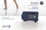
Keypads
SSPA single- and dual-pump systems are available with
a selection of keypads.
All the procedures and instructions described in the next pages are applicable to
SSPA systems equipped with one of the following keypads. Please note that the
TSC-9 model is used througout this manual to illustrate specific actions.
SSPA-MP (only)
TSC-35 Keypad (7" • 3 1/4")
SSPA
TSC-19 Keypad (7" • 3 1/4")
TSC-18 Keypad (5" • 2 1/2")
TSC-9 Keypad (2" • 4 1/2")
5
SSPA Spa Pack Service Manual
Electrical Wiring
Correct wiring of the electrical service box, GFCI box and pack terminal
bloc is essential.
1• Carry out a visual inspection to check for signs of miswiring.
Refer to supplied wiring diagrams.
Call an electrician if necessary.
For 240 VAC systems:
L2
N
G
L1
Electrical Box
GFCI
Pack Terminal Block
For 120 VAC systems:
L2
N
G
L1
Pack Terminal Block
SSPA Spa Pack Service Manual
6
GFCI Flow Chart
If GFCI trips, follow this Troubleshooting Flow Chart to identify
the problem:
yes
no
Is GFCI
properly connected?
yes
no
Verify
Wiring Diagram
and reconnect it.
Is spa pack
a 120 VAC system?
yes
no
Is Jumper #1
in LC position?
(see page 10)
Change
Jumper #1 position.
yes
no
Is GFCI
still tripping?
yes
no
Unplug everything
including the two blades
of the heater & light cord.
Is GFCI
still tripping?
yes
There is
a problem
with the
cable.
Call an
electrician!
no
If GFCI is
still tripping,
disconnect
incoming
power line.
Reconnect
one component
at a time until
GFCI starts tripping.
Replace defective
component.
Replace
GFCI.
Is GFCI
still tripping?
Replace Spa Pack
if GFCI
is still tripping.
7
SSPA Spa Pack Service Manual
GFCI Trips!
If all connections are made, but nothing seems to be working, you
probably have a power supply problem. Carry out the following tests
to identify and correct the problem:
Note that for new installations, GFCI trippings due to miswiring are common.
If breaker is wired properly, GFCI trippings may occur when total amount of current
drawn by spa exceeds breaker rating.
A current leak to ground will also cause GFCI to trip. If any of the components is faulty
and a leak of more than 5mA occurs, GFCI will trip to prevent electrocution.
There are different GFCI models on the market. Note that illustrations are generic only.
For 120 VAC systems:
For 240 VAC systems:
Jumper location
1• Verify if Jumper #1 is set in
the LC position. If it is not,
set Jumper #1 in the LC
position.
Refer to page 10 for more
information on jumpers.
From electrical box
To spa
1• Verify if GFCI is properly
connected.
Important
connections:
Neutral of GFCI
must be connected
to neutral bus.
Neutral from spa
must be connected
to breaker.
From electrical box
To spa
2• If it is not, verify GFCI wiring
diagram and reconnect it.
SSPA Spa Pack Service Manual
8
GFCI Trips!
If GFCI continues to trip even after having replaced the transformer,
carry out the following tests to correct the problem:
1• If GFCI is properly connected, but
still tripping, (or Jumper #1 is set in
LC mode for 120 VAC systems),
unplug all outputs
including the
two blades of
the heater
and light cord.
3• If problem is not solved yet,
disconnect incoming power
lines.
2• If GFCI still trips, replace Spa Pack.
4• If GFCI stops tripping, replace
GFCI.
If it stops tripping, reconnect one
component at a time until GFCI
starts tripping. Replace defective
component.
9
If GFCI still trips, there must be
a cable problem.
Call an electrician!
5• If GFCI trips again, replace
Spa Pack.
SSPA Spa Pack Service Manual
Jumper Positions
Certain SSPA spa pack parameters can be modified by changing the
position of jumpers on the board.
To access jumpers, first remove SSPA power box cover.
In some cases, jumper functions may differ from the following. Please check wiring
diagram on power pack box cover to verify specific functions for your pack.
Position 1
Position 2
Jumpers
1• Jumpers are located in the lower
right section of the board.
2• To change a setting, simply pull cover
off and replace in desired position.
Jumper 1: Current Limiting Option
Jumper 1 is used to limit amount of current drawn when the 2 pumps are on.
Position 1 (HC):
Position 2 (LC)*:
*Mandatory for 120 VAC systems
System turns heater off when the two pumps are on
at high speed.
System turns heater on when one pump is on at high
speed. The "Heater" icon flashes on display indicating
that more heat is requested, but heater is not allowed
to start.
Jumper 2: Temperature Unit
Jumper 2 is used to select the temperature unit.
Position 1:
Position 2:
Temperature will be displayed in Fahrenheit degrees.
Temperature will be displayed in Celsius degrees.
Jumper 3: Pumps
Position 1:
Position 2:
SSPA Spa Pack Service Manual
Single-pump.
Dual-pump (or blower).
10
Flashing Dots Flow Chart
If 3 flashing dots appear on keypad display, follow Troubleshooting Flow
Chart below to identify the problem:
3 flashing dots appear on the display!
(FLO, FLC or HL errors)
yes
no
Remove pack cover.
Is board LED on?
Flashing dots indicate an
hi-limit (HL) condition.
Refer to HL pages of this
manual to correct the problem.
Turn off pump that heats water
(circulation pump or Pump 1).
yes
no
Are dots
still flashing?
11
It's an FLC
problem.
It's an FLO
problem.
Refer to FLC
pages of this
manual to
correct the
problem.
Refer to FLO
pages of this
manual to
correct the
problem.
SSPA Spa Pack Service Manual
Display Flashing Flow Chart
On SSPA-NE packs, if system detects temperature at 112°F or higher,
the display will start flashing. Follow Troubleshooting Flow Chart below to
identify the problem:
yes
no
Press
any key.
A power failure
has occurred.
Has display
stopped flashing?
System
works fine.
yes
no
Are you getting correct
water temperature
reading on the display?
yes
no
Is weather
very hot?
Verify if
temperature probe
is touching water
or if cold air from
back can affect
reading.
If so, replace probe
and reset breaker.
Remove
spa cover
(even during
the night).
Start
blower, if
spa is
equipped
with one.
Wait until
spa cools
down (add
cold water
if needed).
13
yes
Replace
board.
Verify if
temperature probe
is properly connected.
Replace
board if
problem
still persists.
no
Lower set point
below actual
water temperature.
"Heater" indicator
on keypad display
should disappear.
Do you get a
240 VAC reading
between two
heater wires on
the board?
Pump is
overheating
water during
filter cycle.
Lower
filter cycle
duration.
SSPA Spa Pack Service Manual
Wrong Temperature Flow Chart
On SSPA-NE packs, if system detects that temperature is not within
normal limits, wrong temperature will be displayed. Follow Troubleshooting Flow Chart below to identify the problem:
Make sure to use the right probe!
MSPA-1 probe does not work on an SSPA spa pack.
Probe wires should be in this order:
PIN #4
Black
Green
Red
PIN #1
Press any key after each step to reset the system.
Check if regulation
probe is properly connected.
Unplug probe connector
and clean pins on the
board (even a small coating
of film may cause a bad
connection).
Reconnect the probe.
Replace probe with
a spare and verify if
problem is solved.
If it is, replace
probe with spare.
Replace board if
problem persists.
15
SSPA Spa Pack Service Manual
FLO Flow Chart
If FLO error condition occurs (problem with the pressure switch: pump is
on but no water pressure detected), follow Troubleshooting Flow Chart
below to identify the problem:
Make sure circulation pump parameter is set correctly
(depending on your system configuration).
There must be adequate water
in spa for normal use.
yes
no
Is pump working
when you try to start
it from keypad?
yes
Refer to "Pump not
Working" section.
no
Is anything limiting
flow of water into pipes?
Remove
anything
obstructing
filter.
Clear any
air locks
and verify
water valves.
Verify if
pressure switch
cable is properly
connected
to pressure
switch.
yes
Adjust or
replace
pressure switch.
17
no
Lower Set Point at 60°F and
turn pump off.
Short two pressure switch
terminals with a jumper cable.
Does FLC
error condition
persist?
Replace
Spa Pack.
SSPA Spa Pack Service Manual
FLO Error Condition
An FLO error condition indicates a pressure switch problem. If system
does not detect any pressure when pump is manually or automatically
turned on, an FLO error condition will occur.
There must be enough water in the spa for normal operations. FLO error condition may
occur if spa filter is dirty or if something restricts flow of water in piping.
The heater will automatically shut down when an FLO error condition occurs.
Power may remain On when the following steps are carried out.
Make sure circ. pump parameter is set correctly (depending on your system configuration).
1• Verify if pump is working.
If pump is not working right,
refer to "Pump does not
Work" section.
2• Clean filter and check for air
blockages, closed trap valves
or anything that could be
restricting water flow.
3• Verify if pressure switch cable is
properly connected to pressure
switch.
SSPA Spa Pack Service Manual
18
FLO Error Condition
4• If problem has not been solved,
lower Set Point at 60° by pressing
on Down arrow key and turning
pump off; then short two pressure switch terminals with jumper
cable.
5• An FLC error condition should
occur.
FLC error condition identifies
pressure switch as source of
problem.
Try readjust pressure switch. If
this isn't possible, replace switch.
(Refer to "How to Adjust the
Pressure Switch" section of this
manual.)
6• If FLC error condition does not
occur, problem may be either
with switch cable or board.
Replace Spa Pack.
19
SSPA Spa Pack Service Manual
FLC Flow Chart
If FLC error condition occurs, follow Troubleshooting Flow Chart below to
identify problem (usually pressure switch problem - pump is off but water
pressure is detected):
yes
no
Disconnect
pressure switch cable
on pressure switch.
Does FLO error condition
occur when pump is on?
Adjust
pressure
switch.
Replace
pressure switch
if FLC error
condition
persists when
you start or
stop pump.
21
Replace
Spa Pack.
SSPA Spa Pack Service Manual
FLC Error Condition
An FLC error condition indicates a pressure switch problem. If
system detects any pressure when pump is off, an FLC error
condition will occur.
Power may remain On when the following steps are carried out.
1• Disconnect pressure switch cable
on pressure switch.
2• Replace Spa Pack if FLO error
condition does not occur.
If FLO error condition occurs when
pump is started, adjust pressure
switch or replace it.
(Refer to "How to Adjust the
Pressure Switch" section of this
manual.)
SSPA Spa Pack Service Manual
22
Prr Flow Chart
If Prr error condition occurs (potential regulation sensor problem), follow
Troubleshooting Flow Chart below to identify the problem:
Make sure to use the right probe!
MSPA-1 probe does not work on an SSPA spa pack.
Probe wires should be in this order:
PIN #4
Black
Green
Red
PIN #1
Press any key after each step to reset the system.
Note that water temperature
must be over 35˚F to operate spa.
Check if regulation
probe is properly connected.
Unplug probe connector
and clean pins on the
board (even a small coating
of film may cause a bad
connection).
Reconnect the probe.
Replace probe with
a spare and verify if
problem is solved.
If it is, replace
probe with spare.
Replace Spa Pack
if problem persists.
23
SSPA Spa Pack Service Manual
Prr Error Condition
The Prr error condition indicates a problem with regulation sensor.
The system is constantly verifying if temperature probe reading is
within normal limits.
Note that water temperature must be over 35°F in order to carry out the following steps.
Press any key after each step to reset the system.
Power may remain On.
Note: Make sure to use the right
probe! MSPA-1 probe does not
work on a SSPA spa pack.
Probe wires should be in this order:
Probe
connector
pins
PIN #4
Black
Green
Red
PIN #1
2• Disconnect probe connector
and clean probe connector pins.
Even a small coating of film may
cause a bad connection.
3• Reconnect probe.
If Prr error condition still persists,
replace probe with a spare and
place probe head directly in spa
water.
1• Verify if regulation probe is
properly connected.
If problem is solved, replace
probe.
4• Replace Spa Pack if problem
persists.
SSPA Spa Pack Service Manual
24
HL Flow Chart
If HL error condition occurs (potential hi-limit probe problem), follow
Troubleshooting Flow Chart below to identify the problem:
Press any key after each step to reset the system.
yes
no
Take water temperature
with a digital thermometer.
yes
no
Is water temperature
119°F or higher?
Are you getting correct water
temperature reading on the display?
yes
no
Is weather
very hot?
Remove
spa cover
(even during
the night).
Start
blower, if
spa is
equipped
with one.
Wait until
spa cools
down (add
cold water
if needed).
Verify if
temperature probe
is touching water
or if cold air from
back can affect its
reading.
yes
Replace
Spa Pack.
Verify if
temperature probe
is properly connected.
If so, replace
probe.
no
Lower Set Point
below actual
water temperature.
Pump is
overheating
water during
filter cycle.
"Heater" indicator
on keypad display
should disappear.
Replace
Spa Pack if
HL error
condition still
persists.
Lower
filter cycle
duration.
Do you get a
240 VAC reading
between the
two heater wires
on the board?
yes
Verify if anything
is obstructing water
flow (closed traps or
dirty filters).
No
When HL error
condition occurs,
does heater
barrel feel hot?
Verify if
Hi-Limit probe is
properly connected.
Try to clean pins
and reconnect
probe.
If HL error condition persists,
replace Spa Pack.
25
SSPA Spa Pack Service Manual
HL Error Condition
The HL error condition is related to the Hi-Limit sensor.
Steady message: Means system has shut down heater because water
temperature at the heater has reached 119ºF.
Blinking message: Means except for the Smart Winter Mode, system has shut
down because water temp. in the spa has reached 112ºF.
Press any key between each step to reset the system.
Power may remain On.
1• Take water temperature with
digital thermometer.
2• If reading is below 119°F:
a- Check if heater barrel feels hot.
If it's hot, verify if anything is
obstructing water flow
(closed valves or dirty filter).
b- If HL error condition persists,
replace Spa Pack.
3• If reading is 119°F or higher:
Proceed to following page if
keypad display shows correct
temperature.
Proceed to page 22 if keypad
doesn't show correct temperature.
SSPA Spa Pack Service Manual
26
HL Error Condition
If digital thermometer water temperature reading is 119°F or higher
and keypad display indicates correct temperature, carry out the
following tests.
If weather is very hot:
To shorten filter cycle duration:
1• Remove spa cover (even during
the night). Start blower if spa is
equipped with one. Wait until
spa cools down (add cold water
if necessary).
5• Press and hold
Light key for
5 seconds.
Display will
show a value
that represents the filter
cycle duration in hours.
If hot weather is not a factor:
Use Down
arrow key
to lower
the number
of hours.
0 = no filtration
12 = continuous filtration
2• Lower Set Point below current
water temperature.
The "Heater" indicator should
disappear from keypad display.
When the
desired setting
is displayed,
press Light key
again. The filter
cycle will start
immediately.
6• If you do read 240 VAC,
replace Spa Pack.
3• Remove plastic cover. With
a voltmeter, read voltage
between the two heater
wires on the board.
4• If you do not read 240 VAC,
pump may be overheating
water during filter cycle.
Shorten filter cycle duration.
27
SSPA Spa Pack Service Manual
HL Error Condition
If digital thermometer water temperature reading is 119°F or higher
and keypad display isn't showing correct temperature, carry out the
following tests.
1• Verify if temperature probe
is in contact with water and if
cold air from the back could
be affecting readings.
Use foam to isolate probe from
cold air if that is the problem.
2• Make sure temperature probe
is properly connected.
If it is, replace probe.
3• Replace Spa Pack if HL error
condition still persists.
SSPA Spa Pack Service Manual
28
"Nothing Seems to Work!" Flow Chart
If nothing seems to work, follow Troubleshooting Flow Chart below
to identify the problem:
yes
no
For 240 VAC systems:
Verify if
keypad is
connected
correctly
to board.
All eight pins
must be plugged in
and black wire
must be on top
of the plug.
Do you read
≈ 240 VAC
between
line 1 & line 2,
≈ 120 VAC
between
line 1 & neutral,
≈ 120 VAC
between
line 2 & neutral
on the board?
For 120 VAC systems:
Do you read
≈ 120 VAC
between
line 1 & neutral?
There is
an electrical
wiring
problem.
Call an
electrician.
Is there a
jumper cable
connected
between
line 2 & neutral?
Replace Spa Pack
if there is still nothing
on keypad display.
29
SSPA Spa Pack Service Manual
Nothing Works!
If everything is connected, but nothing seems to work, there is probably a
power supply problem. Carry out the following tests to identify and correct
the problem:
For 240 VAC systems:
4• If you do not get good readings,
this probably indicates an electrical
wiring problem.
Call an electrician!
1• On the terminal block, measure
voltage between line 1 and line 2.
You should get ≈240 VAC.
For 120 VAC systems:
2• Measure voltage between
line 1 and neutral.
1• Measure voltage between
line 1 and neutral.
You should get ≈120 VAC.
You should get ≈120 VAC.
3• Measure voltage between
line 2 and neutral.
You should get ≈120 VAC.
SSPA Spa Pack Service Manual
2• Verify that there is a jumper cable
connected between line 2 and
neutral.
30
Nothing Works!
If you are getting good voltage readings, but nothing seems to work,
carry out the following tests to correct the problem:
1• Verify if keypad is correctly
connected to the board.
2• If nothing works, replace
Spa Pack.
31
SSPA Spa Pack Service Manual
"Spa Not Heating" Flow Chart
If the spa does not seem to be heating the water, follow Troubleshooting
Flow Chart below to identify the problem:
yes
Refer to
specific section
referred to
error message.
no
Any error messages
(FLO, FLC, 3 flashing dots, etc.)
on keypad display?
yes
Ensure temp.
Set Point is
higher than
actual water temp.
no
Has "Heater" indicator appeared
on keypad display?
yes
no
yes
no
Take water temp.
and compare with
temp. value displayed
on keypad.
Do you get a 240 VAC
reading between
the two heater
terminals
on the board?
Is difference
greater than ±2°F?
System
works fine.
Is temp. probe
touching water or
hot air rear
affecting reading?
Replace
Spa Pack.
yes
Isolate back of
probe with foam.
no
Are heater nuts
connected
properly
to the
element?
Replace
temp. probe
with spare.
yes
no
Try tightening nuts
to element.
Still not heating?
If water temp.
still doesn't
match temp.
on keypad display,
replace Spa Pack.
Replace
element.
33
SSPA Spa Pack Service Manual
Spa Not Heating!
If the spa does not appear to be heating the water, carry out
the following tests to correct the problem:
If "Heater" indicator does not
light up:
1• Check for an error message on
keypad display. If there is one,
refer to section indicated by
the error message.
"Set Point"
indicator
4• Use a digital thermometer to take
water temperature and compare
your reading with the value on
keypad display.
If values are different (±2°F), verify if
sensor is touching water or if hot air
from rear could be affecting readings.
5• If so, use foam to isolate behind
the probe.
2• If there is no message, try to
increase temperature by raising
temperature Set Point. Press Up
arrow key to increase Set Point.
"Heater"
indicator
6• If not, replace temperature sensor
with a spare one.
3• Verify if "Heater" indicator appears
on the display.
7• If spa is still not heating, replace
Spa Pack.
"Heater" indicator will be on when
heater is on. It will flash if more
heat has been requested, but
heater has not yet started.
SSPA Spa Pack Service Manual
34
Spa Not Heating!
If "Heater" indicator appears on the display, but spa is still not heating,
carry out the following tests to correct the problem:
If "Heater" indicator lights up on the display:
1• Remove plastic cover and measure
voltage between the two heater
screws on the board.
Replace board if you are not
getting a reading of ≈240 VAC.
2• If voltage reading is correct,
verify if heater nuts are
properly connected to the
element.
If not, tighten nuts to the
element.
3• If problem persists, replace
the element.
35
SSPA Spa Pack Service Manual
Pump 1 Flow Chart
If Pump 1 is not working, follow Troubleshooting Flow Chart below
to identify the problem:
yes
no
Have any error
messages (FLO, FLC,
3 flashing dots, etc.)
appeared on
keypad display?
Refer to
specific section
indicated by
error message.
yes
Verify if Jumper #3
is set properly.
no
Does "Pump 1"
indicator
appear on
keypad display
when you press
Pump 1 key?
Replace
keypad.
If still not working,
replace Spa Pack.
yes
no
Is Pump 1 working
in either speed?
yes
no
Replace Pump 1 fuse.
Pump 1 still not working!
yes
no
Measure voltage on
the board for both speeds.
Replace
Pump 1.
37
Do you get a 240 VAC
reading (or 120 VAC
for a 120 VAC pump)
for both speeds?
Replace
Spa Pack.
SSPA Spa Pack Service Manual
Pump 1 Does Not Work!
If Pump 1 is not working, carry out the following tests to correct
the problem:
To increase the life of the relay, we use a "snubber" circuit on the pump relay.
With this type of circuit, if no pump is connected to an output and relays are open,
the voltmeter will continue reading around 60 volts. This is normal.
It is important to measure voltage when pump is connected to pack.
Power must remain On.
1• Check for an error message on
keypad display. If there is one,
refer to specific section indicated
by error message.
4• If "Pump 1" indicator does not appear,
use a spare keypad to verify if keypad
is defective.
Jumpers
If it is, replace keypad.
2• Also, verify that Jumper #3 is
set properly for 1 or 2 pumps
(refer to page 10 for more info).
"Pump 1"
indicator
If not, replace Spa Pack.
5• If "Pump 1" indicator appears when
Pump 1 key is pressed, verify if pump
works in either speed.
3• Verify if "Pump 1" indicator appears
on keypad display when you press
Pump 1 key.
SSPA Spa Pack Service Manual
38
Pump 1 Does Not Work!
If Pump 1 does not work in either speed, carry out the following tests
to correct the problem:
Pump 1 fuse
1• If Pump 1 does not work in either speed,
replace Pump 1 fuse.
2• If replacing the fuse is not effective or
if Pump 1 works in only one speed,
take voltage reading on the board for
both speeds.
3• Turn Pump 1 to low speed and take
voltage reading between white and
black wire connectors:
240 VAC pump: P14 & P18
120 VAC pump: P7 & P14
Your reading shoud be:
≈240 VAC for a 240 VAC pump
≈120 VAC for a 120 VAC pump
4• If voltage is as it should be,
replace Pump 1.
5• If not, replace Spa Pack.
Turn Pump 1 to high speed and take
voltage reading between white and
red wire connectors:
240 VAC pump: P12 & P18
120 VAC pump: P7 & P12
Your reading shoud be:
≈240 VAC for a 240 VAC pump
≈120 VAC for a 120 VAC pump
39
SSPA Spa Pack Service Manual
Pump 2 or Blower Flow Chart
If Pump 2 or blower does not work, follow Troubleshooting Flow Chart
below to identify the problem:
For SSPA Dual-Pump Systems only!
yes
no
Have any error
messages (FLO, FLC,
3 flashing dots, etc.)
appeared on
keypad display?
Refer to
specific section
indicated by
error message.
yes
Verify if Jumper #3
is set properly.
no
Does "Pump 2"
or "Blower"
indicator
appear on
keypad display
when you press
Pump 2 or
Blower key?
Replace
keypad.
If still not working,
replace Spa Pack.
yes
no
Is Pump 2
or blower working?
yes
no
Replace blower fuse.
Pump 2 still not working!
yes
no
Measure voltage on
the board.
Do you get a 240 VAC
reading (or 120 VAC
for a 120 VAC pump)?
Replace Pump 2
or blower.
41
Replace
Spa Pack.
SSPA Spa Pack Service Manual
Pump 2 or Blower Does Not Work!
If Pump 2 or blower does not work, carry out the following tests to
correct the problem:
For SSPA Dual-Pump Systems only!
To increase the life of the relay, we use a "snubber" circuit on the pump relay.
With this type of circuit, if no pump is connected to an output and relays are open,
the voltmeter will continue reading around 60 volts. This is normal.
It is important to measure voltage when pump is connected to pack.
Power must remain On.
1• Check for an error message on
keypad display. If there is one,
refer to specific section indicated
by error message.
4• If "Pump 2" or "Blower" indicator
does not appear, use a spare keypad to verify if keypad is defective.
Jumpers
2• Also, verify that Jumper #3 is
set properly for 2 pumps (refer
to page 10 for more info).
If it is, replace keypad.
If not, replace Spa Pack.
"Pump 2"
indicator
3• Verify if "Pump 2" or "Blower"
indicator appears on keypad
display when you press Pump 2
or Blower key.
SSPA Spa Pack Service Manual
42
Pump 2 or Blower Does Not Work!
If Pump 2 or blower does not work, carry out the following tests
to correct the problem:
Pump 2 or blower fuse
3• If voltage is as it should be,
replace Pump 2 or blower.
4• If not, replace Spa Pack.
1• If Pump 2 or blower does not work
even when indicator is on, replace
Pump 2 or blower fuse.
2• If replacing the fuse is not effective,
take voltage reading on the board.
Turn Pump 2 or blower on and take
voltage reading between white and
black wire connectors:
240 VAC pump or blower: P11 & P17
120 VAC pump: or blower: P9 & P11
Your reading shoud be:
≈240 VAC for a 240 VAC pump or blower
≈120 VAC for a 120 VAC pump or blower
43
SSPA Spa Pack Service Manual
Spa Light Flow Chart
If spa light does not appear to be working, follow Troubleshooting Flow
Chart below to identify the problem:
no
yes
Have you
tried replacing
the spa
light bulb?
yes
yes
Try
replacing
light bulb.
Is light
still not
lighting
up?
no
Does "Light"
indicator
appear on
keypad
display when
you press
Light key?
no
Replace
keypad.
If still not
working,
replace
Spa Pack.
yes
Replace spa
light socket.
no
Do you get a
12 VAC reading
on light output
on board?
Replace spa
light fuse.
Replace Spa Pack
if light is still not working.
45
SSPA Spa Pack Service Manual
Spa Light Does Not Work!
If spa light is not working, carry out the following tests to correct
the problem:
It is important to measure voltage when light is connected to pack.
Power must remain On.
1• The first step is to replace the
spa's light bulb.
"Light"
indicator
2• If light still isn't working, verify if
"Light" indicator appears on
keypad display when you press
Light key.
4• If "Light" indicator appears, but
light still isn't working, remove
plastic cover and measure
voltage between two light wires
on the board.
If you get ≈12 VAC, replace light
socket.
Light fuse
3• If "Light" indicator doesn't appear,
use a spare keypad to verify if spa
keypad is defective.
If it is, replace keypad.
If not, replace Spa Pack.
SSPA Spa Pack Service Manual
5• If you aren't getting a voltage
reading, replace light fuse on
the board.
6• If problem persists, replace
Spa Pack.
46
Ozonator Flow Chart
If the ozonator is not working, follow Troubleshooting Flow Chart below
to identify the problem:
Ozonator output will be shut down when
Pump 1, Pump 2 or blower have been turned on manually.
yes
no
Has "Filter Cycle"
indicator
appeared on
keypad display?
yes
Start up
a filter
cycle.
no
Do you read
120 VAC for a
120 VAC ozonator
(or 240 VAC for 240 VAC)
on the board?
yes
no
Is Pump 1
working?
Replace
ozonator.
47
Replace Spa Pack
if you still
aren't getting
a voltage reading.
Refer to
"Pump 1 does
not Work!"
section.
SSPA Spa Pack Service Manual
Ozonator Does Not Work!
If ozonator isn't working, carry out the following tests to correct
the problem:
To increase the life of the relay, we use a "snubber" circuit on the ozonator relay.
With this type of circuit, if no ozonator is connected to an output and relays are open,
the voltmeter will still get a reading of around 60 volts. This is normal.
It is important to take voltage reading when ozonator is connected to pack.
Power must remain On.
Please take note that ozonator output will be shut down when Pump 1, Pump 2 or
blower have been turned on manually.
"Filter Cycle"
indicator
1• Verify if "Filter Cycle" indicator
appears on keypad.
2• If not, start up a filter cycle.
Press and hold
Light key for
5 seconds.
The display
will show a
value that
represents the filter
cycle duration in hours.
Press Light key
again. The filter
cycle will start
immediately.
3• Measure voltage between
ozonator black and white
connectors:
240 VAC ozonator: P16 & P19
120 VAC ozonator: P16 & P8
You should read ≈240 VAC
(≈120 VAC for a 120 VAC
ozonator).
4• Replace ozonator if you get a
good voltage reading.
5• Check if Pump 1 is working.
If so, replace Spa Pack.
If Pump 1 is not working, refer
to "Pump 1 does not Work!"
section.
SSPA Spa Pack Service Manual
48
Keys Flow Chart
If any of the keys on the keypad do not seem to be working, follow
Troubleshooting Flow Chart below to identify the problem:
Make sure to use the proper keypad: TSC-35 keypad with SSPA-MP spa pack.
TSC-18, TSC-19 or TSC-9 keypad with SSPA-1 spa pack.
Also refer to Jumper Section (p. 10) to see if outputs are set correctly.
yes
no
Is Jumper #3
set properly for 1 or
2 pumps?
Set Jumper #3
properly.
Unplug spa keypad
and replace with
spare keypad.
yes
no
Are keys
working?
Replace
keypad.
49
Replace
Spa Pack.
SSPA Spa Pack Service Manual
Keys Don't Work !
If any of the keys do not seem to be working, carry out the following tests
to correct the problem:
Make sure to use the proper keypad: TSC-35 keypad works with a SSPA-MP spa pack. TSC-18,
TSC-19 or TSC-9 keypad works with a SSPA-1 spa pack. Also refer to Jumper Section (p. 10) to
see if outputs are set correctly.
Jumpers
1• Verify that Jumper #3 is set properly for 1 or 2 pumps (refer to
page 10 for more info.)
3• Verify if keys respond correctly.
4• If they do, replace keypad.
5• If they do not respond,
replace Spa Pack.
2• Replace spa keypad with a
spare keypad.
SSPA Spa Pack Service Manual
50
How To Replace The Spa Pack
When replacing an SSPA spa pack, it is important to make sure to turn
power off before proceeding.
1• Unplug Pump 1, Pump 2 (or blower)
and ozonator connectors.
2• Remove 2 screws from front pack cover.
3• Lift the Spa Pack cover.
51
SSPA Spa Pack Service Manual
How To Replace The Spa Pack
When replacing an SSPA spa pack, it is important to make sure to turn
power off before proceeding.
4• Disconnect power input cables.
Light
Keypad
Probe
5• Disconnect light cables, keypad
and temperature probe connectors.
7• Disconnect heater ground
cable.
6• Disconnect pressure switch
cable.
8• With wrenches, free the
board blades by removing
the 2 heater nuts.
SSPA Spa Pack Service Manual
52
How To Replace The Spa Pack
When replacing an SSPA spa pack, it is important to make sure to turn
power off before proceeding.
9• Slide the pack out of the heater
barrel.
13• Reconnect light cables, keypad
and temperature probe.
10• Check if high-limit sensor is
properly in place in its slot and
slide new pack into position.
14• Plug in Pump 1, Pump 2 (or
blower) and ozonator connectors.
11• Connect heater to the board
blades. It is important to hold
both nuts when tightening. If
you bend or twist the end of
the element, you may damage
it.
15• Reconnect power input
cables.
16• Close pack cover.
12• Reconnect heater ground
cable and pressure switch
cables.
53
SSPA Spa Pack Service Manual
How To Adjust The Pressure Switch
When a voltmeter is available:
1• Set voltmeter to "Ω" (while both
probes are touching one another,
voltmeter should beep to show
there is continuity).
2• Turn pump off.
3• Do you have continuity on pressure switch?
If you have no continuity, go to
step 4.
If you do have continuity, increase
pressure switch setting by turning
clockwise until voltmeter stops
beeping. Then, decrease another
1/4 of turn.
4• Turn pump on at low speed and
wait a few minutes.
If FLO does not appear, you have
adjusted the pressure switch successfully.
If FLO appears, decrease pressure
switch setting by turning counter
clockwise until voltmeter starts
beeping (there is continuity). Then,
decrease another 1/4 of turn. Turn
pump off.
FLC Should not appear (restart procedure if FLC appears).
5• When adjustment procedure is
completed, apply Loctite 425 to
the adjustment screw to secure
it in place.
SSPA Spa Pack Service Manual
54
How To Adjust The Pressure Switch
When a voltmeter is not available:
1• Turn pump on at low speed.
2• Increase the pressure switch
setting to 4 P.S.I. or until FLO
message is displayed.
3• Start decreasing pressure switch
setting by very slowly turning
adjustment screw counter
clockwise until FLO message
disappears. Then, decrease
another 1/4 of turn.
4• Turn pump on at high speed for
30 seconds; there should be no
FLO message.
5• Turn pump off and wait 30 seconds.
You should not see an FLC message.
6• Turn pump to low speed for 30
seconds. You should not see an
FLO message.
7• If you see an FLO or an FLC
message, restart the adjustment
procedure.
If you are not able to adjust the
pressure switch, change it.
8• When adjustment procedure is
completed, apply Loctite 425 to
the adjustment screw to secure
it in place.
55
SSPA Spa Pack Service Manual
Parts List
We recommend that field service technicians keep the items
identified with an * in stock.
57
Ref.: Part Number
Description
1
1
2
4
6
6
6
6
6
6
6
6
6
6
6
6
12
12
13
19
22
23
29
30
Tail piece for 2" heater
Gasket for 2" tail piece (package of 5)
Nut for 2" heater
Light cords (option LS)
J&J mini connector for pump 1
J&J mini connector for pump 2, single speed
J&J mini connector for pump 2, two speeds
J&J mini connector for ozone
J&J mini connector for blower
J&J mini connector for circulation pump
AMP connector for pump 1
AMP connector for pump 2, single speed
AMP connector for pump 2, two speeds
AMP connector for ozone
AMP connector for blower
AMP connector for circulation pump
In-line 5.5Kw heater
5.5Kw 240V element for in-line heater
Pressure switch
Ground screws (package of 25)
Fuses for light (package of 10)
Fuses for pumps (package of 10)
Fuses for transformer
10-foot temperature probe
530AB0061
530AB0042-P5
282CA0071
9920-400178
9920-400200
9920-400199
9920-400200
9920-400204
9920-400203
9920-400205
9920-400277
9920-400276
9920-400277
9920-400278
9920-400278
9920-400276
530AA0107
530AB0087
510AD0064
282AD0038-P25
430AC0103-P10
430AE0033-P10
430AD0066-P10
9920-400262
Retail U.S.
CDN
5.39
8.00
4.90
7.57
7.26
6.68
7.26
5.92
5.92
5.92
7.26
6.68
7.26
6.68
6.68
6.68
143.17
88.20
28.42
9.86
11.14
56.57
11.14
19.20
7.33
10.88
6.67
10.3
9.88
9.09
9.88
8.06
8.06
8.06
9.88
9.09
9.88
9.09
9.09
9.09
194.79
119.99
38.67
13.42
15.15
76.97
15.15
26.12
*
*
*
*
*
*
*
SSPA Spa Pack Service Manual
Wiring Diagram (SSPA-1)
The wiring diagram below provides a general idea of SSPA-1 wiring, but it is important to
note that it may not apply to all systems. The wiring diagram including on inside power
box cover is the one to be used as main reference for the spa you are servicing.
Pump 1
Voltage
Green / Ground
Black / Low Speed
Red / High Speed
White / Com
240v
P4
P14
P12
P18
Pump 2
Voltage
Green / Ground
Black / Line
White / Com
240v
P6
P11
P17
Jumper Settings
Refer to page 10
Ozonator
Voltage
Green / Ground
Black / Line
White / Neutral
120v
P5
P16
P8
Light Connector
White / 0 VAC
Black / 12 VAC
P23
P22
Heater
Black 1
Black 2
P20
P21
Pressure Switch
Green
Red
P25
P24
Wiring Diagram (SSPA-MP)
The wiring diagram below provides a general idea of SSPA-MP wiring, but it is important
to note that it may not apply to all systems. The wiring diagram including on inside
power box cover is the one to be used as main reference for the spa you are servicing.
Pump 1
Voltage
Green / Ground
Black / Low Speed
Red / High Speed
White / Com
120v 240v
P4
P4
P14 P14
P12 P12
P7
P18
Pump 2
Voltage
Green / Ground
Black / Line
White / Com
120v 240v
P6
P6
P11 P11
P9
P17
Jumper Settings
Refer to page 10
Ozonator
Voltage
Green / Ground
Black / Line
White / Com
120v 240v
P5
P5
P16 P16
P8
P19
Blower
Voltage
Green / Ground
Black / Line
White / Com
120v 240v
P37 P37
P34 P34
P35 P36
Fiber Box
Voltage
Green / Ground
Black / Line
White / Neutral
120v
P1
P33
P35
Light Connector
White / Light
Black / 12 VAC
P23
P22
Heater
Black 1
Black 2
P20
P21
Pressure Switch
Green
Red
P24
P25
Professional Repair Kit
All you need in one case!
Gecko's professional repair kit contains
all you need to service and repair
Gecko's line of power spa packs.
•
•
•
•
•
•
•
•
•
•
•
•
•
•
•
Call 1.800.78.GECKO
to order or for more info!
Top side controls (keypads)
Temperature probes
Pressure switch cables
Flow switches
Elements
Heater wires
Transformer
Ground lugs
Grommets
Standoffs
Light cords
Strain reliefs for light cord
Plugs
Fuse kits
Screws
SSPA SERVICE MANUAL
COMPLETE SERVICE GUIDE WITH
STEP-BY-STEP INSTRUCTIONS ON:
GFCI Troubleshooting
•
Jumper Setup
•
Understanding
& Correcting
Error Messages
•
System Malfunctions
•
Part Replacement
Procedure
•
& More
GECKO
1.877.GECKO • www.gecko-electronic.com
9919-100298
A Handy-Dandy
Guide to Heaters
with
Information on the Causes &
Corrections of the Bad Things That Can
Happen
v
,
.
Mechanical Failures
Brand New Element
The term “Mechanical Failure” covers everything from
shipping damage to dog bite, but the most common
mechanical failures in electric heaters are caused by
improper handling - destroying the Epoxy End Seal, and
breaking or twisting the Cold Pin until it breaks are the two
leaders in this failure mode. Because they are so closely
related we'll look at them together.
WHAT HAPPENS?
Any form of rough handling can put pressure on the part of the heater that sticks
out the most - the Electrical Terminal, which is welded to the Cold Pin, which in
turn passes through the Epoxy End Seal to get to the Heating Coil inside of the
A Sidebar
element. If the Electrical Terminal is
When
we
talk
about
“Mechanical” failure we
broken away from the Cold Pin there is
must remember that heaters have no moving
obviously no way to connect electrical parts. There is nothing to “wear out”. There
wires to the heater, and it becomes a are no parts that spin, turn, jerk, or slide, and
no gears to mesh, or hinges to squeak. All of
throwaway.
the mechanical failures we can name are
More often the rough handling results caused by people doing things they shouldn’t
in the destruction of the Epoxy End Seal. do, or neglecting to do the things that they
This will allow moisture to get into the should do.
inside
of
the
element where it will be absorbed by the MGO Filler and
will eventually cause an electrical short circuit between
either the electrically "hot" Cold Pin or Heating Coil, and
the electrically grounded Outer Sheath of the heater. With
luck, there will be a GFCI on the system that will open the
BROKEN EPOXY SEAL
circuit.
If you don't know what caused the GFCI to turn the power off, you might
start investigating "nuisance tripping".
Without the GFCI there will eventually be arcs, sparks, flames and anger - you can
bet on that.
HOW CAN THIS BE PREVENTED?
BAD COLD PIN WELD
TWISTED COLD PIN
Moisture may get inside of the element when it is off.
Part of the cooling off process is to suck in any surrounding
air through any crack. Then, the next time the element is
energized, the moisture in the element may provide a path for
current to flow, and the GFCI will trip. But, a BIG BUT - the
heater may have been on just long enough to produce
enough heat to drive that moisture out of there. You come
along and reset the GFCI - and the heater will come back on
again. Drive ya nutty, as they say. Check that Cold Seal
carefully.
Never bend, push, pull or twist the Electrical Terminal 1 Always use two
wrenches to tighten or loosen the Terminal Nut 2 . One wrench holding the Terminal Hex
4 to keep it from turning, and one on the Terminal Nut to do the tightening or loosening.
The trick to analyzing this failure is to carefully examine the Cold Seal. Signs of
severe fracture or chipping are an almost sure bet that the Cold Seal is no longer able to
do its job - to seal. If the heater has been acting strange - erratic - sometimes working
fine and other times tripping the GFCI: look at that Cold Seal.
THE NOISY HEATERS – HUMS, VIBRATIONS, SQUEALS, TWITTERS,
SHREKS, SCREAMS, RATTLES, WHISTLES, TWEETS, & CHIRPS
Rarely, maybe never, is the element itself at fault when noise is reported in a
heater, even though it is the element that is usually making the noise. The huge amount
of water moving rapidly past the element can set up some wild vibration patterns as it
twists and turns through the heater. Usually it is simply a matter of re-aligning the
element by a bit of gentle bending to move it away from the heater housing; or tying the
noisy part down with a clip or wire made for the purpose. Check with us.
Dry Fire – The Ultimate Element Destroyer
SETTING THE STAGE
SHEATH BURNEDOUT DUE TO DRY
FIRE
In normal operation the heaters that we deal with daily
in pools and spa operate at temperatures only a few degrees
above the temperature of the water that is flowing past them.
If the thermostat in a spa is set to maintain the water at 102o,
for example, the temperature of the Incoloy Outer Sheath
will be about 110o. The water flowing past the element is
carrying the heat away just about as fast as the element can
produce it. Everyone is happy.
WHAT GOES WRONG?
One of three things can happen - A) the water flow slows
down too much, B) the water flow stops, or C) the heater is
somehow turned on with either no water in the housing, or
only partially filled. The results will be the same: the Incoloy
Outer Sheath temperature will rapidly rise - 200o - 500o DISCOLORED
1,000 o - 1,500o in a matter of just a minute or two. The
HEATER TUBE
melting point of the Sheath is 1700o to 1800o F, and it will get
DUE TO DRY FIRE
there quickly unless it isn't turned off by some safety device
like a high-limit switch. The failure can show up in several different ways:
ü The Outer Sheath splits open. The Heating Coil
wire is hanging out in all directions
and the MGO Filler is cracked, smashed and blown away. The element is totally
destroyed, and frequently the Stainless Steel Heater Housing may be damaged as
well.
ü Just one or two small holes are blown through the Sheath - not as dramatic as a
complete, explosive meltdown, but just as costly. The element is destroyed.
üNo holes are visible, but the walls of the Sheath are bulged outward in spots, the
normally smooth surface of the Sheath is now bumpy and has become discolored.
Inside of the element the Heating Coil may be broken; or it might be electrically
shorted against the Sheath. Or both.
WHY? WHY? WHY?
That’s three good questions. Lets take a look at a few of the
things we have learned from a lot of field experience plus a
ton of hours in the engineering lab:
MELTED PRESSURE
SWITCH
HIGH LIMIT PROTECTION – the primary job of the
High Limit Switch in the finished product is to prevent
scalding water from ever reaching the people using the
product. Sure, the Thermostat should shut the heater off
long before the point at which the High Limit Switch is
needed, but Thermostats, like everything else, fail.
Will the High Limit do its job? It hasn’t had to
operate for months or years – is it ready? Is it in the right
place to do the job? If the High Limit is not sensing the water temperature close to the
element, and the pump suddenly quits – its dry fire time in just a minute or two. The
element will boil the water in the heater housing – and create its own “dry” condition.
Following that, the service technician arrives and finds the heater assembly full
of water again, and claims it couldn’t have been a dry fire. Check that High Limit.
FLO/PRESSURE SWITCHES – Various types of devices are used to detect
whether there is any water flowing through the heater assembly. Unfortunately, when
these things fail, they generally fail in the closed position and there is no indication that
they are not doing their job. In most cases a spa system will work just fine with a stuck
pressure or flow switch – until there is a need for it.
If a full-scale dry-fire destroys the flow or pressure switch along with the element,
it’s impossible to determine which went first; but one thing is certain – the heater was
doing its job. It isn’t very smart – it just makes heat.
Attack of the Killer Chemicals
CORROSION – the Bad Guy
It's a mean, angry sounding word, bringing visions of all sorts of nasty things. Even
the dictionary makes it sound pretty evil "...akin to RODENT" no less. Come to think of
it, we've seen a few heaters that looked like rats had been gnawing on 'em.
cor ž rode (kä rod´) v.
1. to eat or wear away gradually as if
by gnawing, esp. by chemical action
ME (<MF) <L corrodere to gnaw; akin
to RODENT
BULKHEAD CORROSION
We think it's a safe bet to say that one of
the major causes of heater failure has always
been corrosion. Given any chance at all, this
demon will destroy a heater element or , in
many cases, the entire heater.
The corrosion we come across in our
industry, particularly in spa equipment, comes in many
varieties, each with it's own name and characteristics - we
are faced with galvanic corrosion, chemical pitting,
intergranular corrosion, stress corrosion cracking,
corrosion fatigue, electrochemical corrosion - we even
have a strain of bacteria: Ferrobacillus in the
Siderocapsaceae family, also called "iron eating bacteria,"
to contend with. Gee Whiz.
WHAT CAUSES ALL THIS?
Well, a full discussion of the chemistry and
electrochemistry involved with this pretty complex subject
is beyond the intent of this Handy-Dandy Guide. It's much
easier to describe what doesn't cause it than to attempt to
explain all the chemistry that does. Consider this: if all
BAD CORROSION ON
those spas out there were filled with clean, pure water,
ELEMENT
and no one ever added any chemicals to them, the word
corrosion would soon leave our vocabulary.
Unfortunately, that's not going to happen, and all those spas are going to continue
being filled with water of every type, from the Cascade
Mountain's rain water to big-city sludge.
A DEADLY SOUP
ZIPPERED ELEMENT
EXTREME
CALCIFICATION
Then, to add to the problem, we have learned that many,
many spa owners are not following all of the instructions they've
been given about pH, Total Alkalinity, Calcium Hardness and
Total Dissolved Solids; or about how to handle those unique
water problems that may exist in their spa when it is filled with
water from their tap.
LOW pH – BOO! HISS!
If we had to pick the worst offender in the corrosion list, it
would definitely be LOW pH, because, as we all learned long ago: when a test sample of
the water shows a LOW pH (below 7.0), it indicates the water is ACIDIC. Remember
now, this is not just saying that there is ACID in the water - it says that the water has
become an ACID. It doesn't matter at all what kind of ACID caused this to happen hypochlorous, hydrochloric, hypobromous, muriatic or whatever - when the water
becomes an ACID it becomes a starving, hungry, corrosive beast looking for lunch.
ACIDS will corrode – eat away – almost any metal in their path in order to satisfy that
hunger.
An element or heater corroded because the water has a LOW pH is easy to spot – it
has pieces eaten away from its surface. Gone, disappeared, departed. It looks like the
craters of the moon. And people are putting their bodies in there!
SCALE/CALIFICATION – HISS! BOO!
At the other end of the ---- we have SCALE. In some ways SCALE can be considered
as the opposite of ACID: with SCALE the water has too much of something and wants to
get rid of it, and the nice warm heating element is a good place to deposit it, The
problem is that it’s like asking a Hawaiian to run a marathon in Honolulu dressed in a fur
coat, wool cap and mukluks. He’s going to have a rough time getting rid of the heat he’s
generating, and probably won’t finish the race.
MORE UGLINESS
Bad-chemistry corrosion can show up where the element sheath is brazed to the
bulkhead fitting, or welded to a mounting plate. Even though all of the parts are
“stainless” steel, and selected just for this purpose, the ingredients (mostly iron,
chromium, nickel and molybdenum) in the steel must vary – the mix has to be different
for parts like the Bulkhead Fitting that needs to be machined, vursus the thin, high
temperature Incoloy Outer Sheath that must be bent and formed.
Very special welding techniques are used at these joints
to make sure that no impurities are left behind that might
corrode. But, if the water gets bad enough, you may see
anywhere from a rust-like deposit to crack and fissures in
the metal.
RUST BUILD-UP ON
ELEMENT
At its worst it can result in “corrosion fatigue”, causing
the Bulkhead Fitting to breakaway from the Outer Sheath.
This corrosion is bad stuff.
AND THEN: THERE’S THE IRON EATER
BACTERIA RESULT
A slippery, brownish coating on the inside wall of a spa
may not be any form of algae, but can be the effects of an
“iron eating bacteria” that is gnawing away at the heater.
This one is easy to correct – the water simply needs some
sanitizer: chlorine, bromine or ozone here, a drain and refill
if it won’t go away.
WHAT’S THE BOTTOM LINE ON CORROSION?
Corrosion of the metal in a pool or spa heater happens when the water becomes
corrosive because somebody makes mistakes with its chemistry.
There are more than 2,000,000 spas in the USA alone that have never shown any
signs of corrosion – some more than twenty years old.
Their owners follow the instructions of the professionals at their local pool/spa store,
and maintain a good sanitizer level along with a non-corrosive pH level, and monitor
their Total Alkalinity, Calcium Hardness and Total Dissolved Solids for a good water
balance. They do not “Throw in a little of this or a little of that.” That’s like signing a
Pledge Of Corrosion.
Electrical Failures
DO THEY EVER JUST “BURN OUT”?
It's correct to say that the only "natural" - like in "died of natural causes," - electrical
failure that a resistance-wire heater ever suffers is when the Heating Coil
breaks,
causing an OPEN in the circuit. This is also the only electrical failure ever covered by
our warranty.
It's exactly the same as a light bulb burning out - it just gets tired of the tremendous
trauma it goes through each time the power is applied. Picture it - it goes from cold to
very, very hot in less than 1/10th of a. second - it opens its door to see who's knocking
and a thousand billion billion electrons (that's 21 zeros!) rush in during the first second.
Because of the careful selection of components in the Heating Coil, this sort of failure
is actually quite rare. (You will rarely see a light bulb burn out while it was on? Probably
never - they always burn out just as you turn them on. That's "turn-on trauma")
However, it can be brought on more quickly by switching the heater on and off rapidly this can happen with a defective control, such as a chattering contactor or thermostat,
for example. Be very suspicious if a replacement heater burns out quickly. Watch for
this.
Another suspect in an OPEN situation is a reduced water flow that causes the
element to operate at a much higher temperature than normal, but not high enough to
cause a dry-fire condition. There may be no signs of the problem on the outside of the
element - it just got tired of working too hard.
A Special Note To Our Manufacturer and Assembler Customers:
Please remember that both Aquatemp and the original manufacturer of the heater
element have run the required Dielectric Voltage Withstand Test ("Hi Pot Test") on every
unit we build. Both of us are very careful to keep the test time to the absolute minimum
allowed to prevent any degradation of the dielectric material within the element.
everything You always wanted to know
about testing of the electric part
of electric heaters
TYPICAL TEST
METER
Of any piece of equipment you might find on a spa or tub
today, the electric heater is probably the most simple - we're
not talking here about the controls, now - just the heater itself.
What makes it simple is that it is a straight resistive device. It
doesn't have any coils like motors and transformers, giving
them inductive charact- eristics; and it isn't anything at all like
a solid state, printed circuit board mounted, micro- processor
based control system. With heaters, the electrical is plainJane.
THE IMPORTANT NUMBERS
You can learn just about all there is to know about an electric heater by applying a
little knowledge and a smidgen of easy math, along with a decent test meter. We'll start
with the basic numbers:
¥ These first two numbers are stamped or marked on the heater .
Rated Voltage, like:
Rated Wattage, like:
115, 120, 240, or 230 volts
1500, 5500 watts or
¥ These next two are calculated using the above numbers:
Calculated Amperage, like:
Calculated Ohms, like:
12.5, 22.9, 25, or 48 amps
5.0, 9.6, or 10.5 ohms
The math part is kept simple by
using our Handy-Dandy Decoder
Ring, shown at right. Let's say you
want to figure the amps rating of a
heater marked 240 volts & 5500 watts.
Use W/V that would be 5500 divided
by 240, and the answer is 22.9 amps.
Simple.
W
A2
V
A
V2
W
W
O
O = A=
OHMS
WxO
VOLTS WATTS
V= W =
V
O
V x A
A2 x O
A xO
W
A
¥ The next three are measured
with a meter at an operating heater:
Measured Voltage, like:
Measured Amps, like:
112, 227, or 238 volts
11.5, 21, 24.6, or 44 amps
USING THE NUMBERS
AMPS
W
V
2
V
O
Measured Ohms, like:
All that follows applies to all electrical heaters. The task is
simple – to determine if the heater is producing heat (watts); and
then make sure that it is safe – these are the facts, ma’am.
USING TEST
METER
First, measure and compare the voltage at the heater
terminals with the voltage at the panel board, receptacle or other
power source. Don’t blame the hater for poor performance if this
Measured Voltage is more than 10% below the heater’s Rated
Voltage. (Do the math V2/O, to see how quickly the watts drop as
the volts drop.)
¥
If the Measured Voltage was much different than the Rated Voltage, you’ll have
to re-figure the Calculated Amps using V/O. (You can’t use W/V because you’re not sure
what the wattage is anymore.) Then, with power still on, put your clamp-on ammeter
around ONE of the heater wires – either one, but only one. You’re now reading
Measured Amps, which should match the Calculated Amps number, within 10%.
¥
Turn OFF all power, then DISCONNECT BOTH WIRES from the heater
terminals. Set the meter to the OHM;s scale and take the following readings at the
element terminals:
Terminal – to terminal: the Measured Ohms should read within 10% of
Calculated Ohms.
From each terminal, one at a time, to the element sheath or element mounting
plate: should read OPEN or INFINITY. ANY OTHER READING says the element is
internally shorted. This is a bad element. Look for signs of dry fire damage.
That’s it. You now know all there is to know about the electric stuff in the heater. You can
now re-calculate the wattage using the voltage, amps and ohms numbers you have
measured, confident in your knowledge.
The Meter Sidebar
A good test meter is a must if we are to learn what's going on in the electric heart of that
heater. Take full advantage of today's technology and check out the latest units that
combine the digital volt/ohm meter with a clamp-on ammeter. It's like they knew about
electric heaters when they designed these guys. Check out B&K Precision's 330 & 340;
A.W. Sperry's DSA-2007,
and others by Radio Shack, Fluke and Scope. All are available in the $80 - $100 range.