1
ServiceInsights
FOR
INDEP E N D E N T
S E R V I C E
C E N T E R S
JUL–SEP 2015
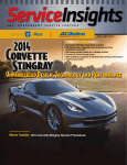
2016 CORVETTE ZO6
MOST CAPABLE CORVETTE EVER!
More Inside:
■ Service Procedures for the Corvette
■ GM Unveils Reman Option for Duramax Turbocharger
gmserviceinsights.com
GMSERVICE
M
IN
Contents
3 / GM 6-Speeds, TEHCM
Programming Front and Center
at Fall ATRA Powertrain Expo
GM ServiceInsights Online
Read more at GMServiceInsights.com
More Genuine GM Parts
resources and links.
3
4 / New, Revised Training Topics
in Place for GM Technical Training
Clinic Program
Download this issue and past issues
of GM ServiceInsights magazine at...
Read more at GMServiceInsights.com
4
www.gmserviceinsights.com
GM ServiceInsights Headquarters
2604 N.E. Industrial Dr., #230
N. Kansas City, MO 64117
Email: [email protected]
5 / GM Clinic Instructor Jerry Mungle
Makes Learning Fun
We Support Voluntary Certification
National Institute for
AUTOMOTIVE SERVICE EXCELLENCE
www.ase.com
5
6 / Gen V Marine Debut
Nautique Boats Powered by GM/
Pleasurecraft Engines at 2015
Masters Tournament
Compliments of your GM dealer.
We invite your input and suggestions.
Please address letters to the editor to the above address. Letters submitted imply the right to edit and publish.
Every effort is made to ensure the accuracy of the information in the offers contained in this magazine. However,
printing and typographical errors may occur. These are not intentional and are not the responsibility of GM, any
dealer or the companies or individuals who create, produce and distribute this magazine. Offers and pricing may
change at any time without prior notification. The descriptions and specifications in this publication were in effect
at the time of approval for printing. General Motors reserves the right to change specifications without notice and
without obligation. Published letters do not necessarily reflect the opinions of General Motors or General Motors
Parts. General Motors, Detroit, MI 48202.
© 2015 General Motors • All rights reserved.
6
Read more at GMServiceInsights.com
8 / GM Unveils Reman
Turbocharger Line for Duramax
Engines
Read more at GMServiceInsights.com
8
9 / TIS2Web Subscription Opens
Up New World of GM-Vehicle
Diagnostics, Programming
Read more at GMServiceInsights.com
9
10 / 2016 Corvette ZO6 Most
Capable Corvette Ever
Read more at GMServiceInsights.com
10
12 / 2015 Corvette Service Procedures
www.gmtechinfo.com offers access for
service manuals and other repair resources.
Follow this example for the Corvette.
12
16 / TechConnect Insert
Diagnosing Voltage Drops
•
Place the
service
Trouble-
Free Program
components and wiring in the circuit, through vehicleit’s
ground,
and back toPC
thenext
battery
negative terminal. Components include the
to or
a laptop
inside
Several
ming
compute
• A
vehicle on
factors to
battery, wiring, terminals, relays, switches and other
controls,
other items,the
depending
r).
laptop the load, and various
(if the circuit.
consider
compute
include:
to help ensure
r should
the laptop
be plugged
trouble-f
battery
in to ensure
ree program
will bethe
Measure
voltage between
the battery positive post and the
program
maintain
ming
ming event.
Dedicate
ed
positive feed at the fuelduring
pump connector
with the fuel pump
the service
the
Connect
the PC to
PC (laptops
PC inside
commanded
on (using a scan tool) and with a load
applied,
the Internet/
the such
preferre
quality LAN
vehicle during
d) — Placing
TIS2Web headlamp. Thededicate
cable as
program
a small sealed-beam
multimeter
orfrom
via a
d towill
a laptop
reliable
access point.
that
ming ensures
Business
accidentthe two function. This
display the difference Grade
in voltage potential between
the PC remains
ally interrupt
helps
Wi-Fi
Connect
the PC to points — the voltage drop.
ing the program to minimize risk
PC. Laptops
the J2534
device using
are preferre
ming process of someone
program
in the vehicle
d because
the USB
ming interface
• Connect
cable
their portabili by multitasking
and the
Measure Resistance?
a battery Why Notmethod.
the
internal
the event
ty permits
battery
maintain
of a tempora
maintain
placemen
If excesser
resistance
is the cause of the problem
in a
or equivale
proper battery
ry AC power provides additiona
A power
t
nt
supply
to
l insuranc
when required
interrupt
voltage circuit, it may seem logical to use an
malfunctioning
should be
e in
during program
ion during
used at all
.
• To
program
T ensure
ohmmeter to measure
and locate
the excess resistance.
times.
ming
ming.
the compute
Prevent
But
this is not a good idea for several reasons. PC going
Microsof
r remains
into sleep
t Window
active, adjust
to conserve
mode
s®
“Power
—
power using
the
a circuit. Current, also called amperage, is the“High
measure
of
performa
Options.
adjust the of an
Power Managem
nce” power
” Select
First, the ohmmeter
sends only
Window
sleep in
the a few thousandths
plan
s® Power
ent techniqu
either ‘On
going
set it tothough the circuit.
amp, calledand
a milliamp,
This
to does
Options
Battery’
sleepnot
es. Disable
“Never”
during
to prevent
or
or
simulate‘Plugged
the reality
a circuit that normally carries higher the program
the compute
In’ofmodes.
Recomm
some amount of resistance. When electrons
are held
back by
ming event.
r from
ended
Choosin
Process
amperage.
During
g an MDI
a resistance, fewer of them are available
to do the
the
Rational
SPSwork
e
connecti
program
connecti
on method
ming, the
circuit was designed for.
ons are critical
required
for SPS
Second,
thedata/c
ohmmeter uses its
Reliabilit
to the success
—
J2534
/ alibration
y takes preceden
device
of module
own power supply, so the
Connect
The difference between the amount service
of electrons on either
ce over convenie
program
ing the device
ming.
PC before
circuit being tested
nce,
recomme
directly
side of the resistance is the amount of electrons that
didn’t
module
to the service so keep it simple.
nded in
program
mustming
be isolated
order to
make it through — that “dropped out.” This results in voltage
PC via the
the PC and
can
maintain
and the
USB cable
vehicle module
(disconnected) begin. When
an errorrequired
drop. Excessive resistance causes excessive voltage
drop,
and
r free connecti
is
method
data
(via the
is then transmit
the vehicle
is simple,
temporarily from
on between
J2534 device
easy and
module
problem
ted from
and DLC).
eliminate
by way of the vehicle’s
battery.
to interfere
the PC to
This
the J2534
in a malfunctioning circuit.
while transmit s any potential for
program
device
Again this
does not
ming.
and DLC.
a network
ting data
to the module
simulate reality.
retrieval diagnosis calls for
For example, if a fuel pump isn’t operating,
during
, it may be
Quality/
necessar
y Reliabilit
verifying system voltage and ground at the fuel pump electrical
y to restart
y of shop
And third,
a very small amountuseGE\U
of
or recover
network
connector using a digital multimeter
But if there is
error(DMM).
HSDLUVKR
and
develops
(LAN) —
SVYDULHV
resistance — possibly too small
to be
recomme
Wi-Fi hardwar
while transmit
JUHDWO\D
corrosion on the fuel pump relayiscontact
nds Business
a risk ofor ground connection
QGLVGLIĆ
ting to
e
damage
measured
accurately with an(AP).
ohmmeter — can
have a very
the vehicle,
FXOWWRTX
Grade hardwar
to the chassis, there might be enough
voltage potential
for the
to the
Hard-wir
unrecove
DOLI\*0
vehicle module
there on high amperage
ed cable
e for the
large effect, particularly
circuits
likeconnecti
the
rable.
reliable
Because
multimeter to read correctly, but
the
circuit
voltage
may
drop
Wi-Fi
that
may be As an example, athan
Access Points
the service
ons to the
of this, a starter motor
Wi-Fi and
resistance
of only
USB connecti circuit.
PC to MDI
LAN are
off under load.
Fi connecti
may be
consider
is a best
on.
from 12-volt circuit will
0.01 ohm in aon
200-amp
cause
a drop of 2 more suitable
ed more
Beware
practice.
if not
such as deteriora
that cables
volts (Ohm’s Law: voltage = current
x resistance).
are still prone near a reliable
tion of the
Wivisually
to
cable or
physical
evident.
connecto
damage,
If a cable
r which
r,
is suspect
is not alw
substit
What Is Voltage Drop?
•
•
13
TechConnect is a magazine to help
professional technicians improve their
knowledge and understanding of
today’s increasingly complex vehicles.
18 / Arkansas Body Shop Owner
Indulges his passion with GM Rewards
18
2 Jul – Sep 2015 ServiceInsights
GM 6-Speeds, TEHCM Programming
Front and Center at ATRA Powertrain Expo
GM will share important information on
profitably working with advanced GM
transmissions at this fall’s ATRA 2015
Powertrain Expo.
GM Customer Care & Aftersales will present a
comprehensive seminar on servicing GM 6-speed
transmissions. It will cover the finer points of diagnosing,
servicing and replacing 6-speeds.
A special emphasis will be the Transmission Electro
Hydraulic Control Module. The TEHCM is a component of
all GM 6-speed transmissions. It optimizes shifting, fuel
economy, operating life and overall performance.
But it must be programmed to operate correctly. The
seminar will review how Independent Service Centers (ISCs)
working on 6-speeds do that using a TIS2WEB interface
and a scan tool.
The event will be patterned after the TEHCM . . . You Can
Fix ’EM seminar presented at the ATRA 2014 Powertrain
Expo. It was well attended by service technicians
interested in GM 6-speed service business opportunities.
GM has made that possible by expanding access to TEHCM
programming beyond GM dealer service centers.
GM continues to make it easy for ISCs to try their hand
at GM 6-speed work. Through the end of 2015, ISCs can get
a no-cost, 2-day TIS2WEB subscription with the purchase
of a GM 6-speed transmission.
“Independent service centers have a great opportunity
to expand into GM 6-speed transmission service work,”
says Michelle Francisco, product specialist, transmission
& transfer case assemblies with GM CCA. “Attending the
ATRA show and taking in our 6-speed and TEHCM clinic is
an ideal way to begin testing the waters of this promising
line of business.”
GM CCA is also planning an 8-speed-transmission
display at its show booth. The 8-speed is a next-generation
GM transmission that service technicians will be required to
understand as they are installed in more GM vehicles.
The ATRA 2015 Powertrain Expo will be held at the
Rio All-Suite Hotel & Casino Oct. 29–Nov. 1, 2015. For
registration information, visit www.powertrainexpo.com.
Jul – Sep 2015 ServiceInsights
3
GMSERVICE
M
IN
GM OE Parts Update
New, Revised Training Topics In Place
For GM Technical Training Clinic Program
GM Customer Care & Aftersales is expanding
its commitment to Independent Shop
technical education in 2015.
GM CCA is adding four brand new service topics to
its course offerings in the GM Technical Training Clinic
program. The clinics are hosted by GM Parts dealers and
the dealer invites their local independent shops to attend
the FREE training.
The new clinics address areas certain to be of interest
to Independent Shops. Two clinics, HVAC Technology
and Service and Brake Service Tips, examine technological
advances making that work more challenging. Today’s
Top Service Concerns offers a wide-ranging discussion of
emerging challenges in diagnostics and repair procedures.
TEHCM Programming reviews procedures for working with
the Transmission Electronic Hydraulic Control Module for
GM 6-speed transmissions.
“We evaluated the entire program with an eye toward
keeping the topics fresh, relevant and on top of new
automotive technology,” says Amyy Hartley GM CCA
wholesale channel associate.
fferings
“That meant taking a look at offerings
re
that covered technologies that were
g or
no longer as relevant and removing
urses
tweaking them, and adding new courses
that cover important automotive
technologies that most impact
shops today.”
g and
GM CCA spent months reviewing
evaluating the clinic program. The effort
drew on input from trainers, dealerss
ned
and independent shops. The combined
insights helped GM CCA refine their
course offerings.
4 Jul – Sep 2015 ServiceInsights
“Feedback from the field team and our customers
was essential to determining the expansion of our clinic
program and its more comprehensive offerings,” says Dale
Tripp, manager, engineering, training, quality and brand
protection. “What we’re offering now is very responsive
to what our customers are looking for in the area of GM
education and training.”
GM CCA has been expanding the geographic reach
of the Technical Training Clinic Program. A network
of experienced and knowledgeable trainers has been
assembled. Now scores of GM Parts dealers across the
country are able to host training for independent shops in
their local markets.
In addition to refining the service clinic offerings, GM
CCA has been revamping the collision repair component of
the clinic program. Clinic offerings for Independent Body
Shop customers of GM Parts dealers have been extensively
updated and enhanced.
e ding a total of 12 brand new clinics this year
“We’re fielding
in hopes of keeping training topics fresh and on top of new
technology,” says Hartley.
GM Clinic Instructor Jerry Mungle Strives to Illuminate
Specifics of GM Vehicle Repair
Just as blind spots put drivers at risk, they
exist in the vehicle repair world, too, and
spell potential trouble for repair technicians.
“Sometimes you don’t know what you don’t know,” says
Jerry Mungle, an instructor in the GM Technical Training
Clinic program.
Mungle is guided by a keen understanding of the need
to confront that problem. In teaching GM dealer-sponsored
clinics for mechanical service and body repair techs, Mungle
tries to highlight specialized facets of GM vehicle repairs.
“It’s getting harder to say that one size fits all anymore,
across different vehicle makes and even within the GM
family of vehicles,” he says. “Two GM vehicles side by side
can be completely different in their structure and design.”
The clinics address that problem by focusing on GMspecific information that can guide techs in the nuances
of repairing GM vehicles. And, while there’s a general script
for each subject area, instructors bring their own style to
the mix. Mungle, who has taught GM repair for 15 years,
is no exception.
Training Should Be Fun
“I really try to make it enjoyable and relevant to what
techs are working on and seeing in the course of their GM
vehicle work,” he says. “I’ve changed my approach over
the years to where it’s a more relaxed and less formal
environment. I like group discussions, question-and-answer
formats and taking the approach of ‘let’s work through this
stuff together.”
It also helps that Mungle has a common bond with his
audience. Before moving into training, he was a Cadillac
master technician. He grew up around cars, too, and has
been involved in drag racing since he was 15.
Mungle found his calling as a trainer after trying his
hand as a contract instructor for the GM Training Center
in Houston while working as a Cadillac tech. He quickly
found that he had a knack for it and joined GM as a regional
instructor. Based in Houston, Mungle teaches GM training
clinics in southern Texas and Louisiana.
“What I like most about it is helping people, knowing
that I’ve made techs’ work lives a little easier and the
service centers that employ them more profitable,” Mungle
says. “The key to becoming a good instructor is being a
good listener. In a roundabout way, if you’re listening your
audience will tell you what they need to know.”
Knowing he can’t cover topics exhaustively in a
three-hour clinic, Mungle’s primary aim is to address key
knowledge points. He supplements that with a discussion
of the availability of extensive additional resources from
GM that techs can consult. He never loses sight of the goal:
arm techs with the understanding that
repairing GM vehicles requires specialized
knowledge, and strive to make sure
they know how to find it and use that in
their work.
“Knowledge is nothing more than
another tool, and the more you have the
better off you’re going to be,” he says.
GM Technical Training Class with Instructor, Jerry Mungle
Jul – Sep 2015 ServiceInsights
5
GM OE Parts Update (contd.)
GM Powered Nautique Boats
Make Their First Appearance at Masters Tournament
slalom, trick and jump events. In earlier qualifying events
for the tournament, held in Orlando, a Ski Nautique 200
pulled a competitor to a world ski jump record. That put
another feather in the boat’s cap. Since its introduction,
At the 56th Annual Masters Water Ski & Wakeboard
it has pulled competitors to 20 world records in different
Tournament, GM and its partners unveiled a brand new
events, triple the number of all competing boats, combined,
GM Gen V engine application.
according to Nautique.
Meanwhile, other GM
“This was absolutely
powered boats pulled several
huge for the engine’s debut
competitors to new records,
tournament,” says Brad
and GM Marine Engines
Gearheart, Nautique senior
shared the spotlight as a
marketing communications
presenting sponsor of the
coordinator.
sport’s premier event.
Meanwhile, another GM
The Gen V GM engine,
engine-equipped Nautique
marinized and supplied by
boat pulled a Master’s
PCM Marine Engines, powered
competitor to a perfect score
Ski Nautique 200 boats built
in the wakeboard competition.
by Nautique Boat Company,
Behind a Super Air Nautique
The
Gen
V
delivers
outstanding
Orlando, FL. PCM is a longtime
G23 equipped with a PCM LSA
GM Marine Engine OEM
engine, Australian superstar
performance, including greater fuel
Partner and exclusive power
Harley Clifford rode to a perfect
efficiency . . . It’s truly the next generation
supplier to Nautique, a leading
100-point run. Perfection had
engine
that’s
superior
in
numerous
ways
ski boat manufacturer.
never been achieved before in
The Ski Nautique 200
any certified wakeboard event.
— Greg Meloon
to the previous engine.
is one of the top water ski
In a press release, Nautique
boats around. It’s even more
president Greg Meloon was
formidable with the new Gen
quoted as saying that the
V engine. Incorporating the
“Super Air Nautique G23
latest GM technology, the
proved once again why it is
Gen V enhances the power,
clearly the best boat in the
efficiency, maneuverability
history of wakeboarding. The
and overall performance that
first-ever perfect 100-point
professional-grade ski boats
run could not have happened
must deliver.
behind any other boat. Equally
In the tournament, staged
impressive were the water
on Robin Lake at Callaway
ski athlete performances
Gardens, Pine Mountain, GA,
behind the amazing Ski
Ski Nautique 200s pulled
Nautique 200; the boat that
scores of competitors to
has dominated the water ski
impressive performances in
world for several years.”
GM Marine Engine Technology made a huge
splash over the 2015 Memorial Day weekend.
“
”
6 Jul – Sep 2015 ServiceInsights
For PCM, too, the tournament was the ideal stage
to unveil the new Gen V-powered Ski Nautique 200.
“The Gen V delivers outstanding performance,
including greater fuel efficiency,” he says. “It’s truly the
next generation engine that’s superior in numerous ways
to the previous engine.”
GM Marine leveraged its role as a presenting sponsor of
the tournament to tout its ski and wakeboard boat-power
solutions. Their display highlighted the new GM/PCM power
options for Nautique boats, which included powering the
Nautique G23 with the Gen V engine beginning with the
2016 model year. GM also brought its Chevy Truck Tour
to the event, which treated attendees to an up-close,
interactive look at the features of the Silverado, Tahoe,
Suburban and all-new Colorado.
“GM has been in the marine business just as long as the
prestigious Masters Tournament, and our partnership this
year reflects our commitment to excellence in the sport
and marine powertrains,” says Patrick Koenigknecht, GM
director of Marine OEM sales.
For more pictures and to read the rest of
the story on Gen V Marine Debut, go to
gmserviceinsights.com
Jul – Sep 2015 ServiceInsights
7
GM to Unveil Reman Turbocharger Line for Duramax Engines
Visit www.gmserviceinsights.com on August 28, 2015 to read the story.
NSIGHTS.COM
TIS2Web Programming Opens
Up New World of GM Vehicle
Diagnostics, Programming
GM’s online Techline
Information System
(TIS2Web) service is the ticket
to performing expanded GM
vehicle service work. In fact,
to be fully capable on GM
repairs, it’s the best game
in town.
TIS2Web is the gateway to
calibration and diagnostic software
specific to GM vehicles. It’s the onestop, go-to source. With it, problems
can be quickly isolated and targeted
repairs performed.
TIS2Web is a web-based subscription
service with various programming
and diagnostic software packages to
fit any business need. Subscribe to
TIS2Web for Global Diagnostic System
2; Tech2 Scan Tool diagnostic software;
Tech 2 Win and Service Programming
System software. The packages
range from limited-duration access
to basic diagnostics capabilities and
unrestricted, year-round passes to the
full suite of GM service resources.
Access to Live Help
Subscribers also get access to live
GM Assistance. That’s a benefit when
help is needed with diagnostic matters.
Assistance is available via phone, e-mail
or remote control of a tech’s PC.
At any level, a TIS2Web subscription
is a modest investment. That’s a
benefit when help is needed with
diagnostic software concerns. An ISC
can tap deeply into the GM vehicleservice database. Paired with the
right hardware, it can yield profitable
work that previously may have gone
to dealer service lanes and specialized
competitors. In addition, it helps
ensure the work is done efficiently and
correctly.
With TIS2Web, shops can keep that
specialized GM vehicle work in house.
In a competitive business where every
piece of business matters, that can be a
game-changer.
“We know many shops send their
customers to their competitors — or
outsource the service programming
— because they didn’t have the right
tools to confidently identify and make
the repair,” says Bob Stewart, with GM
Customer Care & Aftersales. “Or, they
ate into their profits and productivity
by spending hours on a vehicle that
could have been diagnosed and repaired
quickly. That impacts customer service.”
Transmission Flashing
More ISCs are seeing opportunities
in GM 6-speed automatic transmission
work. To do that work, techs must be
able to flash the transmission’s TEHCM
— Transmission Electro Hydraulic
Control Module. TIS2Web is the only
source for those programming tools.
Complete GM Service Support Package
$3,125 per year, includes:
• GMSi
• Tech2 Diagnostic Software Updates
• Tech2 Snapshot
• GDS2*
• Tech2Win**
• Service Programming Software
Tech2 and Service Programming
Package
$1,395 per year, includes:
• Tech2 Diagnostic Software Updates
• Tech2 Snap Shot
• Tech2Win**
• Service Programming Software
Service Programming System (SPS)
Only
$55 2-days, $275 3-months, $995 per
year, includes:
and Saturn software to update
• GM
vehicle calibrations
(GM vehicle calibrations may be looked
up at no charge)
Tech2 Diagnostics
$750 per year, includes:
• Tech2 Diagnostic software updates
GM Global Diagnostic System 2 (GDS2)*
$57 3-days, $227 monthly, $575 per year,
includes:
for specific vehicles
• Diagnostics
beginning in MY2010***
Tech2Win**
$55 3-days, includes:
to emulate Tech2 diagnostics
• Software
on a PC or laptop. (Does not provide
programming capability.)
GM Vehicle Communication Interface
Package
$775 per year, includes:
• GDS2*
• Tech2Win**
For more information about
subscribing to TIS2Web, go to:
www.acdelcotechconnect.com
and click on TIS2Web, under the
title, “Toolbox.”
*GDS2 requires a GM MDI or J2534-2 equivalent.
**Tech2Win requires an ISO 22900 PDU API compliant
device.
***View a list of GDS2 supported vehicles
Jul – Sep 2015 ServiceInsights
9
2016 CORVETTE Z06
MOST CAPABLE
CORVETTE EVER
When the Z06 rejoined the Corvette lineup in 2015
as the most capable model in the car’s long, storied
history, it also joined an elite fraternity of the world’s
most capable supercars. It returns for 2016, offering
more choices for personalization to complement its
world-class levels of performance — including an allnew C7.R Edition.
The C7.R Edition pays tribute to the Corvette Racing
C7.R racecars. It’s offered in Corvette Racing’s signature
yellow livery — or black — with coordinated exterior and
interior accents. Only 500 will be built, all with the Z07
Performance Package with carbon ceramic brakes, and a
specially serialized vehicle identification number.
The Corvette Z06’s capability is rooted in its LT4 supercharged 6.2L V8 engine, which is SAE-certified at 650
horsepower (485 kW) at 6,400 rpm and 650 lb-ft of torque
(881 Nm) at 3,600 rpm — making it the most powerful production car ever from General Motors and one of the most
powerful production cars available in the United States.
With the available Z07 package, its capability enables:
• 0-60 mph acceleration in 2.95 seconds with the eightspeed automatic and 3.2 seconds with the seven-speed
manual transmission
10 Jul – Sep 2015 ServiceInsights
• Quarter-mile times of 10.95 seconds at 127 mph with the
eight-speed and 11.2 seconds at 127 mph with the sevenspeed transmission
• Lateral acceleration of 1.2 g
• 60-0 mph braking in only 99.6 feet — the best of any
production car tested by General Motors.
The Z07 package adds adjustable front and rear aero
components for true aerodynamic downforce, Michelin
Pilot Super Sport Cup tires for enhanced grip, and Brembo
carbon ceramic-matrix brake rotors that improve braking
performance and contribute to greater handling through
reduced un-sprung weight.
The unique grille also features dedicated brake-cooling
intakes and wider grille outlets on the bottom serve as air
diffusers. The grille is complemented with a larger hood
vent, which vents hot air from the engine compartment
and contributes to downforce by allowing air driven through
the grille to exit through the hood rather than being forced
under the car, which could create lift.
Additional cooling elements include larger front fender
vents and unique air blades over the inlets on the rear
fenders of Coupe models, which force about 50 percent
more air into the cooling ducts for the transmission and
differential coolers than those on the Stingray. Convertible
models feature under-body inlets. To cope with the
additional airflow, Z06 Coupe and Convertible also have
larger rear-fascia openings than the Stingray.
Standard front and rear brake-cooling ducts, including
Z06-signature rear ducts integrated in front of the rear
fender openings, are also part of the functional design
changes over Stingray models.
The Z06 also benefits from interior details designed for
high-performance driving, first introduced on the Stingray,
including a steel-reinforced grab bar on the center console
for the passenger and soft-touch materials on the edge of
the console, where the driver naturally braces during highload cornering.
SD-card slot in the glove box for recording and transferring
video and vehicle data (SD card not included). Recording
time depends on the capacity of the memory card, but an
8-gigabyte card can record approximately 200 minutes,
while a 32-GB card stores up to about 800 minutes — more
than 13 hours of driving time.
The PDR system can record video with three data
overlay options, each rendered in real time:
Performance Data Recorder
• Touring Mode — simply records and displays video and
audio of the drive with no data overlay
The award-winning, industry-first Performance Data
Recorder — or PDR — enables users to record high-definition
video, with telemetry overlays, of their driving experiences
on and off the track. It was developed with Cosworth,
the motorsports-engineering company that supplies the
Corvette Racing team’s data acquisition and telemetry
electronics system.
The PDR system includes three major components, all
seamlessly integrated into the Corvette Z06’s interior. First
is a high-definition camera, mounted within the windshield
header trim, which records the driver’s point-of-view
through the windshield. Audio is recorded via a dedicated
microphone in the cabin.
Second is a self-contained telemetry recorder, which
uses a dedicated GPS receiver that operates at 5 hertz,
or cycles per second — five times faster than the in-dash
navigation system, which allows more precise positioning
and corner traces. Finally, the system features a dedicated
• Track Mode — shows the maximum level of data on the
screen, including speed, rpm, g-force, a location-based
map, lap time and more.
• Sport Mode — shows fewer details on the overlay but
includes key data including speed and g-force
• Performance Mode — records performance metrics, such
as 0 to 60 mph acceleration, 1/4-mile speed and elapsed
time, and 0-100-0 mph runs.
The video can be viewed on the Corvette Z06’s
eight-inch color touchscreen when the car is parked, or
downloaded to a computer for further editing, and sharing
video via social media sites. For users who want a more indepth understanding of their performance, the PDR vehicle
data can be opened in the included “Cosworth Toolbox”
software, which combines Cosworth’s professional-level
motorsport data analysis with an easy-to-use graphic
interface.
The Corvette Z06 is built at GM’s Bowling Green, Ky.,
assembly plant.
For more pictures and videos on the
2016 Chevrolet Corvette ZO6, go to
www.gmserviceinsights.com
Jul – Sep 2015 ServiceInsights
11
The Technical Side
2015 Chevrolet Corvette Repair Procedure
Even though the Chevrolet Corvette is a new vehicle, service and repair information resources are a click away at www.gmtechinfo.com
— Electronic Service Information. Technicians and shop owners can log on to the site to gain access to subscription services for service
procedures and repair manuals. A complete Service Manual is accessible 24/7 through a subscription to the site. Free collision repair
procedures will soon be available for the vehicles by going to www.genuinegmparts.com.
Rear Differential Hydraulic System Service Fill/Bleed
Rear Differential Hydraulic System Service Fill/
Bleed Procedure
The rear differential hydraulic system service bleed is used to remove
air from the system, check for proper system and solenoid function, and
determine if full pressure can be achieved at the apply piston. Any time a
rear differential hydraulic line is disconnected or any repairs are made, this
procedure must be performed.
Special Tools
For equivalent regional tools, refer to Special Tools
Connect scan tool and check the rear differential clutch control
module for any DTCs and perform repairs as necessary. The scan tool
may not allow the hydraulic system service fill/bleed if certain DTCs are
present.
1
Raise vehicle. Refer to Lifting and Jacking the Vehicle.
Remove the left rear tire and wheel assembly. Refer to Tire and Wheel
Removal and Installation.
Remove the rear stabilizer shaft clamps and pull shaft backwards for
clearance. Refer to Stabilizer Shaft Replacement.
Disconnect high
pressure line on the
clutch pack (2). Refer to
Limited Slip Differential
Clutch Pipe Connector
Disconnection and
Connection
5
Attach the DT51381 to the high
pressure line. Lead the
high pressure line to a
drain pan.
6
7
8
Remove the fill plug (1). Refer to Differential Clutch Oil Inspection.
Top off Rear Drive
Clutch fill hole with
the appropriate fluid.
Refer to Adhesives,
Fluids, Lubricants, and
Sealers
9
Disconnect the Q49
Rear Differential
Clutch Solenoid Valve (1).
10
11
12
Start engine.
Reconnect the Q49 Rear Differential Clutch Solenoid Valve.
From the scan tool menu, select Rear Differential Clutch Control
Module, then select Control Functions, then Rear Differential
Hydraulic Line Fill.
DT-51381 Limited Slip Differential Clutch Pipe Connector
2
3
4
5
Warning: While engine is operating, the exhaust system will become
extremely hot. To prevent burns avoid contacting a hot exhaust
system.
8
Verify that fluid comes out of the high pressure line through the
DT-51381 three times during the Rear Differential Hydraulic Line
Fill procedure.
13
Note: This is a visual check that will tell if the procedure was done
correctly. If fluid does not come out of the high pressure line three
times, verify there are no internal/external leaks, valve stuck, or the
motor seized before proceeding to the next step.
Top off Rear Drive Clutch fill hole again with appropriate fluid
and repeat Rear Differential Hydraulic Line Fill with scan tool
once more.
14
15
16
17
18
19
20
21
22
Turn engine off.
Remove DT-51381. Reattach high pressure line to clutch pack.
Top off Rear Drive Clutch fill hole again with appropriate fluid.
Install fill plug
Reattach the rear stabilizer shaft clamps. Refer to Stabilizer Shaft
Replacement
Install the left rear tire and wheel assembly. Refer to Tire and
Wheel Removal and Installation
Lower vehicle back down.
Restart engine.
From the scan tool menu, select Rear Differential Clutch Control
Module, then select Control Functions, then Rear Differential
Hydraulic System Service Bleed.
Note: The Rear Differential Clutch Control Module can run this
procedure up to 3 attempts to get a Pass. If this step does not pass,
repeat procedure from step 2.
Note: Status will change to “Complete” when done.
12 Jul – Sep 2015 ServiceInsights
Diagnosing Voltage Drops
components and wiring in the circuit, through vehicle ground, and back to the battery negative terminal. Components include the
battery, wiring, terminals, relays, switches and other controls, the load, and various other items, depending on the circuit.
What Is Voltage Drop?
Measure the voltage between the battery positive post and the
positive feed at the fuel pump connector with the fuel pump
commanded on (using a scan tool) and with a load applied, such
as from a small sealed-beam headlamp. The multimeter will
display the difference in voltage potential between the two
points — the voltage drop.
Why Not Measure Resistance?
If excess resistance is the cause of the problem in a
malfunctioning circuit, it may seem logical to use an
ohmmeter to measure and locate the excess resistance.
But this is not a good idea for several reasons.
a circuit. Current, also called amperage, is the measure of
some amount of resistance. When electrons are held back by
a resistance, fewer of them are available to do the work the
circuit was designed for.
The difference between the amount of electrons on either
side of the resistance is the amount of electrons that didn’t
make it through — that “dropped out.” This results in voltage
drop. Excessive resistance causes excessive voltage drop, and
in a malfunctioning circuit.
For example, if a fuel pump isn’t operating, diagnosis calls for
verifying system voltage and ground at the fuel pump electrical
connector using a digital multimeter (DMM). But if there is
corrosion on the fuel pump relay contact or ground connection
to the chassis, there might be enough voltage potential for the
multimeter to read correctly, but the circuit voltage may drop
off under load.
First, the ohmmeter sends only a few thousandths of an
amp, called a milliamp, though the circuit. This does not
simulate the reality of a circuit that normally carries higher
amperage.
Second, the ohmmeter uses its
own power supply, so the
circuit being tested
must be isolated
(disconnected)
temporarily from
the vehicle’s battery.
Again this does not
simulate reality.
And third, a very small amount of
resistance — possibly too small to be
measured accurately with an ohmmeter — can have a very
large effect, particularly on high amperage circuits like the
starter motor circuit. As an example, a resistance of only
0.01 ohm in a 200-amp 12-volt circuit will cause a drop of 2
volts (Ohm’s Law: voltage = current x resistance).
Jul – Sep 2015 ServiceInsights
13
How to Measure Voltage Drop
4.
5.
If the test leads are reversed, the measurement will be
indicated as negative voltage, although the numerical
value will be accurate.
Operate the circuit.
While the circuit is operating, the multimeter displays
the difference in voltage between the two points.
Because the excessive resistance you’re looking for may be
in the ground connection of the component, be sure to do a
voltage drop test between the circuit’s ground stud and the
battery’s negative terminal.
The voltage drop test is ideal for locating excessive resistance
in a circuit. First, the circuit being tested is not disturbed
in any way by the test, so reality is maintained. Second, the
voltage drop test actually requires the circuit to be operating
during the test. And a high-impedance multimeter offers
very high resistance through its circuitry, so it does not cause
confusion by introducing an alternative path for current to
Never measure voltage in a computer-controlled circuit
unless instructed to do so by a service procedure. Done
incorrectly, or with the wrong instrument, the test could
cause more problems than it locates.
In addition, do not insert digital multimeter test probes
into any connector or fuse block terminal. The diameter
of the test probes will deform most terminals. A deformed
terminal will cause a poor connection, which will result in a
system failure. Always use the properly sized probe from an
appropriate terminal test probe kit in order to front probe
terminals. Do not use paper clips or other substitutes to
probe terminals.
Use a digital multimeter when performing voltage drop tests.
1.
2.
3.
Set the digital multimeter to the V (DC) position.
Connect the positive (red) lead of the multimeter to one
point of the circuit to be tested. Generally, the positive
lead should be connected to the side of the component
closest to the battery positive terminal.
Connect the negative (black) lead of the multimeter
to another point of the circuit. Generally, the negative
lead should be connected to the side of the component
closest to the battery negative terminal (ground).
The amount of voltage drop that is acceptable depends on
the current being carried by the circuit. A lower current
equates to a lower acceptable voltage drop. According
to standards established by the Society of Automotive
Engineers (SAE), 8 milllivolts (mV) is the maximum acceptable
voltage drop in a 16-gauge wire carrying 15 amps.
For a fuel pump, as mentioned earlier, an acceptable voltage
drop should be close to zero, but no more than 1/10 of a volt
for each connection in the circuit.
Repairing the Cause of an Excessive Voltage Drop
If any voltage drop is higher than acceptable, disconnect the
appropriate connections and look for corrosion. Perform
the necessary repairs and test again. Often the very act of
pulling a terminal apart will scrape offending corrosion away.
But to be sure, use approved cleaning procedures. If cleaning
the connectors does not decrease the voltage drop to an
acceptable level, the component itself may be defective, or
may require further examination or testing.
After making the repair, perform the voltage drop test again
Another Consideraধon
To this point, only voltage drops that are higher than design
intent have been discussed. However, voltage drops that are
too low can be a problem, too. Some circuits are controlled
resistance and its resulting voltage drop are too low, the
circuit will fail to operate as designed. For instance, many
sensors in a computer-controlled engine management system
operate on the voltage drop principle. The amount of voltage
drop is interpreted by the computer as a variable operating
condition. A sensor that drops too little voltage (or too much)
will cause improper operation.
(Article originally appeared in ACDelco News & TechConnect)
14 Jul – Sep 2015 ServiceInsights
GM Service Programming System Video
Tutorial on ACDelco TechConnect
GM has added the Service Programming
System (SPS) tutorial to its lineup of videos
covering programming and scan tool
diagnosis for service technicians in
aftermarket repair shops. The SPS video
covers a critical aspect of repairing today’s
vehicles that have an increasing number of
electronic control modules, sensors and
actuators running on multiple data networks
in a vehicle. For most shops, service
programming provides an important revenue
stream and can be a key competitive
differentiator.
SPS is available through an online TIS2Web
VXEVFULSWLRQWRXSGDWHWKHćDVKFDOLEUDWLRQ
ĆOHVVWRUHGLQDYHKLFOHèVRQERDUGFRQWURO
modules. Using a J2534 programming
interface device, SPS communicates with
a vehicle control module to modify it or
reprogram it with newer calibration
information downloaded from the GM
Technical Delivery System website.
Service programming is not complicated, but
it must be done right. Shops that use GM’s
VHUYLFHSURJUDPPLQJVXEVFULSWLRQPD\ĆQG
the service programming learning curve is
smaller than expected. With the right tools and a
$50 SPS subscription, independent service
centers can program vehicle control modules
themselves to maximize the potential of many repairs,
reducing the time and expense of outsourcing the work.
GM’s short SPS video is a key resource along with 11
additional TIS2Web tutorial videos that are now
available to help support independent repair shops that
diagnose and program GM vehicles using GM software
applications. Visit the GM TechConnect website to view
the Service Programming tutorial and other videos. Click
TIS2Web in the Tool Box to learn more about TIS2Web
online or to purchase a subscription.
TAKE ADVANTAGE OF BOSCH DIAGNOSTIC EQUIPMENT REBATE
If you’ve recently purchased Bosch diagnostic equipment for your shop, you
may qualify to receive one or more rebates from the manufacturer this year.
Several products, including the Tech 2 Pro Optima, SMT 300 and CANDI
module, are eligible for the Bosch Diagnostic Equipment Rebate, which has
been extended into 2015. You could receive rebates ranging from $50 to $250.
To see a complete list of qualifying purchases and to access the rebate form, go
to acdelcotechconnect.com. (Also note that Bosch will accept the 2014 form
until an updated version is established online.)
Jul – Sep 2015 ServiceInsights
15
SPS Programming Tips
Before programming a vehicle control module using the
GM Service Programming System (SPS), there are
several steps technicians can take to assist in completing
a successful programming event.
While every repair shop may have a different network
environment, here are a few recommended best
practices.
•
•
•
•
•
•
Place the service PC next to or inside the vehicle (if
it’s a laptop computer).
A laptop computer should be plugged in to ensure
the laptop battery will be maintained during the
programming event.
Connect the PC to the Internet/TIS2Web via a
quality LAN cable or reliable Business Grade Wi-Fi
access point.
Connect the PC to the J2534 programming interface
device using the USB cable method.
Connect a battery maintainer or equivalent to
maintain proper battery voltage during programming
when required.
To ensure the computer remains active, adjust the
Microsoft Windows® “Power Options.” Select the
“High performance” power plan and set it to “Never”
sleep in either ‘On Battery’ or ‘Plugged In’ modes.
Recommended Process Rationale
During SPS programming, the required data/calibration
service PC before module programming can begin. When
and the required data is then transmitted from the PC to
the vehicle module by way of the J2534 device and DLC.
Trouble-Free Programming
Several factors to consider to help ensure trouble-free programming
include:
Dedicate the service PC (laptops preferred) — Placing a laptop
PC inside the vehicle during programming ensures the PC remains
dedicated to that function. This helps to minimize risk of someone
accidentally interrupting the programming process by multitasking the
PC. Laptops are preferred because their portability permits placement
in the vehicle and the internal battery provides additional insurance in
the event of a temporary AC power interruption during programming.
A power supply should be used at all times.
Prevent PC going into sleep mode —
to conserve power using Power Management techniques. Disable or
adjust the Windows® Power Options to prevent the computer from
going to sleep during the programming event.
Choosing an MDI connection method for SPS — J2534 device
connections are critical to the success of module programming.
Reliability takes precedence over convenience, so keep it simple.
Connecting the device directly to the service PC via the USB cable is
recommended in order to maintain an error-free connection between
the PC and vehicle module (via the J2534 device and DLC). This
method is simple, easy and eliminates any potential for a network
problem to interfere while transmitting data to the module during
programming.
Quality/Reliability of shop network (LAN) — Wi-Fi hardware
useGE\UHSDLUVKRSVYDULHVJUHDWO\DQGLVGLIĆFXOWWRTXDOLI\*0
retrieval, it may be necessary to restart or recover and
error develops while transmitting to the vehicle, there
is a risk of damage to the vehicle module that may be
unrecoverable. Because of this, a USB connection from
the service PC to MDI is a best practice.
16 Jul – Sep 2015 ServiceInsights
recommends Business Grade hardware for the Wi-Fi Access Points
(AP). Hard-wired cable connections to the LAN are considered more
reliable than Wi-Fi and may be more suitable if not near a reliable WiFi connection. Beware that cables are still prone to physical damage,
such as deterioration of the cable or connector, which is not always
visually evident. If a cable is suspect, substitute another cable.
Throttle it Back: Check Connections Before Replacing the
Throttle Body or Accelerator Pedal
Automotive engineers continue to work to design vehicle
systems that reduce weight, improve engine performance and
increase fuel economy. One of those systems is the electronic
throttle control system (ETC).
The electronic throttle control system is made up of an
electrically controlled throttle body, an electronic accelerator
pedal and wiring to connect these components to an electronic
control unit, or ECU. Analysis of throttle bodies returned under
warranty shows most are found to be fully functional.
Common Issues
The most
common reason
for electronic
throttle control
malfunctions is high
resistance in one or
more of the sensor circuits between the accelerator pedal and
the ECU or between the ECU and the throttle body. These low
voltage signals can be affected by resistance in the circuits as a
result of poor terminal tension or corrosion.
Another condition is higher than normal idle speed and high
engine speed during deceleration after replacing the throttle
body or cleaning carbon from the area around the throttle
blade.
How to Repair the ETC System
For Diagnostic Trouble Codes (DTC) related to the throttle or
accelerator position sensors, GM offers a variety of wiring
pigtails to repair wiring concerns.
A common pigtail used to repair
the ETC system is part number
PT2713. This pigtail connector
attaches to the throttle body and
comes with six blunt-cut wires and
six crimp ‘n seal splice sleeves to make the electrical
connection to the vehicle wiring harness.
To connect the pigtail to the vehicle harness:
1. Strip 5/16 inch (8 mm) of insulation from the wires to be
joined.
2. Insert one of the wires into the splice sleeve until it hits the
stop position and crimp using Kent-Moore J-38125-8 or
equivalent. Use the crimp tool nest that corresponds to the
3.
4.
5.
color of the splice sleeve. The handles will release when
the crimp is complete.
Repeat step 2 with the remaining wires.
Gently tug on the wires to make sure they are securely
crimped.
Apply heat evenly from the center to the outside of the
splice sleeve using a Mastertech UT-100 or UT-100si
Ultratorch with hot air attachment or a heat gun capable of
producing at least 500° F. The sleeve will shrink around the
metal clip and sealant will come out the ends of the splice.
To help prevent corrosion or fretting concerns in the future,
coat the terminals with dielectric lubricant, GM part number
10-4071.
Idle Learn/Reset Procedure
If there is higher than normal idle speed and high engine speed
during deceleration
after the throttle
body is replaced or
carbon is cleaned
from the area around
the throttle blade:
•
Perform an Idle Learn/Reset. Some vehicles require an Idle
Learn/Reset procedure after throttle body replacement
or cleaning using a Tech 2, GDS2 or equivalent scan tool.
This procedure must be performed with the key on/engine
off. If it is performed with the engine running, the scan tool
may indicate that the procedure is complete when it is not.
The procedure can be found at the following path on the
Tech 2 scan tool (using a 2009 GMC Sierra as an example):
Engine Control Module > Module Setup > Idle Learn Reset.
•
•
viewing the TB Idle Air Flow Compensation PID in scan
tool data. If the procedure was successful, this PID will
show 0%.
If high idle is not corrected by following these steps,
reprogram the Engine Control Module (ECM) to reset the
Idle Air Flow Compensation PID to 0%.
Jul – Sep 2015 ServiceInsights
17
GMSERVIC
M
The Business of Repairs
Points for Pars
Hardworking Arkansas Body Shop Owner Indulges
His Passion With GM Rewards Purchase
For years, Bob Morey has used Genuine GM Parts
to ensure he repairs vehicles professionally, but now
Genuine GM Parts are even helping him on the
golf course.
Morey owns Bob Morey’s Auto Body, Inc., in Bentonville,
AR, and recently cashed in 500 Genuine GM Rewards points
collected for buying qualifying Genuine GM Parts.
18 Jul – Sep 2015 ServiceInsights
Morey said, “I was looking through the golf equipment
section of the reward program merchandise catalog, and
there it was, the exact club I had been thinking about
buying,” he says. “It was great timing. I was able to get it
for nothing out-of-pocket.”
GHTS.COM
Morey’s new driver is helping him improve his
distance and accuracy off the tee. A 15-handicapper,
he’s a regular in a group that plays weekly at courses
in nearby Bella Vista, AR. They all like to show off
the latest gear, and now it’s Morey’s turn to show off
his new Titleist 915 driver.
“I’ve had Titleist drivers before, and this is their latest
and greatest,” he says. “So far, it’s a great club.”
Morey has been enrolled in Genuine GM Rewards for
a couple of years. He started thinking about cashing in
when he noticed his account balance was around 1,000
points. When he learned points could be redeemed for
golf equipment, he made a beeline for the online catalog.
It’s Easy to Claim Your Rewards
“My rep at our GM dealer told me how easy it was to
shop with the Genuine GM Rewards program,” Morey says.
“He knew I wanted that driver, too, and he suggested I
check it out. It took me about five minutes to complete
the purchase and I had the club a few days later.”
With a 500-point balance remaining in his account,
Morey’s plan is to let the points accumulate. That won’t
be a problem because a third of his business is GM
vehicles, and every chance he gets, he chooses Genuine
GM Parts.
“I really prefer to put factory parts on because they’re
consistently higher quality and they fit the first time,”
he says. “My first option is always to see if OE will match
the aftermarket price. It’s a great feeling when you can
tell a customer they’ll get OE parts even when their
insurer will only pay for aftermarket parts.”
Morey isn’t sure what he’ll purchase next with his
Genuine GM Rewards points. Something for his wife and
business partner, Amber, perhaps. Maybe something
for the business. Then, again, there’s always golf. “I saw
that you can get a golf cart for 7,000 points,” he says.
That’s a lot of Genuine GM Parts. But after hearing his
enthusiasm, I’m certain he’ll have those points in no time.
Jul – Sep 2015 ServiceInsights
19