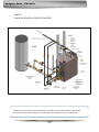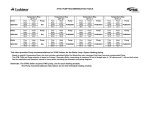
1
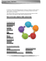
O CM M RC L EO RI LSE R D EHSIIGG HN EERF’ FS I CG IUEI N DC E YS YC N C OE M M IEARLC IBAOL I B Up to 98% Thermal Efficiency w w w . L o c h i n v a r .c o m Designer’s Guide / SYNC Boiler Table of Contents 1 Combustion & Ventilation Air …………………… Page 2 2 Venting 3 Gas ….….…………….……………….………………… Page 13 4 Water …..……………………..……………………….. Page 15 5 Electricity & Controls ……………………………….. Page 21 6 Other Details ..……………………………………….. Page 26 7 Appendix A ….……..…………………………………. Page 29 8 Appendix B …………………………………………… Page 34 ….…………………………………………….. Page 5 . 0 Designer’s Guide / SYNC Boiler At Lochinvar, we know that designing a boiler is hard work. Designing a boiler system is no picnic either. Demands for greater efficiency and elaborate system control have made systems more complex. This designers guide will break down the system requirements that match the SYNC boiler to assure safe operation, highly efficient heating and long life. There are five major elements of boiler system design: Combustion & Ventilation Air Combustion & Ventilation Air (See page 2) Venting (See page 5) Venting Electricity & Controls Gas (See page 13) Water Water Gas (See page 15) Electricity & Controls (See page 21) Plus many other important details: Locations (See page 27 for “Location of Unit”) Suggested Piping Diagrams (See Appendix “A”) High Altitude Requirements (See page 28 for “High Altitude Applications”) Component List (See Appendix “B”) 1 Designer’s Guide / SYNC Boiler Chapter 1 – Combustion and Ventilation Air The first, important design consideration is air. Everybody’s gotta breathe. Even boilers need air. Air seems easy enough. You stand in the equipment room and you breathe comfortably, don’t you? Open a door. Open a window. This is a big room. There’s lots of air in here for the boiler, right? The average person inhales 400 to 500 cubic feet of air in a 24 hour period. A one million Btu/hr boiler will draw 226.38 cubic feet of air every MINUTE! A 20 by 20 by 8 foot equipment room holds 3200 cubic feet of air. That’s a volume of air to last you or me over six days. A one million Btu/hr SYNC will consume 3200 cubic feet of air in 14 minutes. Therefore, a good, easy flow of clean air is 100% necessary for clean, efficient combustion. So, we need to provide a permanent and uninterrupted flow of air to the boiler. The SYNC boiler is designed to receive combustion air by one of TWO methods. The boiler may draw combustion air from the room or have the air ducted directly to the boiler from an exterior space. This chapter explains the methods for “air from the room”. Chapter 2 explains “air ducted directly to the boiler”. Again, this chapter lists several techniques to size the air openings that will deliver room air. If there are other appliances in the room requiring air, their air requirements must be including when sizing the air openings. Provisions for combustion and ventilation air must be designed and installed in accordance with “Air for Combustion and Ventilation”, of the latest edition of the National Fuel Gas Code, ANSI Z223.1, (in Canada, the latest edition of CGA Standard B149 Installation Code for Gas Burning Appliances and Equipment) or applicable provisions of the local building codes. Air NEGATIVE PRESSURE IN THE EQUIPMENT ROOM It is important to NEVER have a negative pressure on the equipment room. Exhaust fans are popular in equipment rooms to exchange the air. If the exhaust fan pulls air OUT, then a negative pressure occurs in the room. The combustion and ventilation air must be sized to supply all the equipment PLUS the air for the exhaust fan. COMBUSTION AND VENTILATION AIR SIZING CALCULATIONS The sizing calculations in this section are based on “Free Area”. The louvers or grill used on the air openings must have a net free area equal to or greater than the value derived in the calculations. The Free Area in a louver or grill is defined as the open, unblocked area. The louvers, grills, mesh, blades, all will block a given amount of space in the louver’s overall dimension. Consult the louver manufacturer for exact net free area of the louver. 2 Designer’s Guide / SYNC Boiler 1. COMBUSTION AIR FROM OUTSIDE If air is taken directly from outside the building with no duct, provide two permanent openings to the equipment room: (a) Combustion air opening, with a minimum free area of one square inch per 4000 Btu/hr input (5.5 cm² per kW). This opening must be located within 12" (30 cm) of the bottom of the enclosure. (b) Ventilation air opening, with a minimum free area of one square inch per 4000 Btu/hr input (5.5 cm² per kW). This opening must be located within 12" (30 cm) of the top of the enclosure. Did you Know? THE SYNC COMES WITH LOUVER CONTACTS AS STANDARD EQUIPMENT. THE CONTACTS WILL OPEN AND CLOSE A MOTORIZED LOUVER ON EACH CALL FOR HEAT. 2. COMBUSTION AIR THROUGH DUCTS If combustion and ventilation air is taken from the outdoors using a duct to deliver the air to the equipment room, each of the two openings should be sized based on a minimum free area of one square inch per 2000 Btu/hr (11 cm² per kW) of input. 3. COMBUSTION AIR FROM INTERIOR SPACE If air is taken from another interior space, each of the two openings specified above should have a net free area of one square inch for each 1000 Btu/hr (22 cm² per kW) of input, but not less than 100 square inches (645 cm²). 3 Designer’s Guide / SYNC Boiler 4. DIRECT OUTSIDE AIR, SINGLE OPENING If a single combustion air opening is provided to bring combustion air in directly from the outdoors, the opening must be sized based on a minimum free area of one square inch per 3000 Btu/hr (7 cm² per kW). This opening must be located within 12" (30 cm) of the top of the enclosure. The combustion air must be free of any contaminants or chemical fumes. Salts, refrigerants and solvents introduced into the combustion process will result in the formation of corrosive acids that will damage the appliance and the vent. 4 Designer’s Guide / SYNC Boiler Chapter 2 – Venting Venting is another important design element for the installation of a gas fired appliance. It has a variety of choices, many different vent configurations to chose from, rules and regulations that govern the installation and most important of all, it bears a requirement for human safety. Warning SPILLAGE OF FLUE PRODUCTS AND CARBON MONOXIDE EMISSIONS PRODUCED BY THE COMBUSTION PROCESS CAN CAUSE SEVERE PERSONAL INJURY OR DEATH. Lochinvar offers five different vent configurations on the SYNC boiler to meet the building’s requirements. They are… Vertical Vent with Air from the Equipment Room Vertical Vent with Air from the Rooftop Vertical Vent with Air from the Sidewall Sidewall Vent with Air from the Equipment Room Sidewall Vent with Air from the Sidewall Venting Part 1 Vent Categories Lochinvar offers five venting options with the SYNC that must be installed with approved Category IV vent material. Below is the vent category diagram, standard throughout the industry. CATEGORY I CATEGORY III Non-Condensing Non-Condensing Non-Positive Pressure Positive Pressure CATEGORY II CATEGORY IV Condensing Condensing Non-Positive Pressure Positive Pressure The four basic Vent Categories are determined by two characterisitics, Condensation and Pressure. In all vent configurations, the SYNC boiler will operate in Category IV. The modulation of the burner down to 10% of the boiler’s input will put low temperature flue products in the stack that will condense. The boiler’s blowers are designed to push the flue products through the exhaust system with a consistent positive pressure. Always use Category IV approved non-corrosive vent material and always seal the joints and connections 100% gas tight in order to prevent condensation and flue gas leakage. 5 Designer’s Guide / SYNC Boiler VERTICAL VENT WITH COMBUSTION AIR FROM EQUIPMENT ROOM. The flue outlet terminates on the rooftop. The combustion air is drawn from the equipment room. BULLET POINTS Category IV vent material is required, such as AL29-4C or PVC/CPVC. All vent joints and seams must be sealed gastight and may not be common vented. All vent material for this configuration including vent termination will be obtained locally. The air is delivered to the equipment room by means defined in Chapter 1 of this designer’s guide. When venting with PVC, the first ten feet of pipe must be CPVC for heat protection. See page 12 of the installation manual for details. MODEL SBN1000 SBN1300 SBN1500 VENT DIAMETER 6" 6" 6" VENT MIN. LENGTH 12 ft 12 ft 12 ft VENT MAX. LENGTH 100 ft 100 ft 100 ft Did you Know? A 90° VENT ELBOW IS EQUAL TO 5 LINIER FEET OF VENT PIPE AND ALL VENT ELBOWS MUST BE ACCOUNTED FOR IN THE TOTAL VENT LENGTH. SEE SYNC I & O MANUAL FOR DETAILS. 6 Designer’s Guide / SYNC Boiler SIDEWALL VENT WITH COMBUSTION AIR FROM EQUIPMENT ROOM. The flue outlet terminates out the sidewall. The combustion air is drawn from the equipment room. BULLET POINTS Category IV vent material is required, such as AL29-4C or PVC/CPVC. All vent joints and seams must be sealed gastight and may not be common vented. All vent material for this configuration including vent termination will be obtained locally. The sidewall termination plate may be used with PVC or CPVC vent material. The air is delivered to the equipment room by means defined in Chapter 1 of this designer’s guide. When venting with PVC, the first ten feet of pipe must be CPVC for heat protection. See page 12 of the installation manual for details. MODEL SBN1000 SBN1300 SBN1500 VENT DIAMETER 6" 6" 6" VENT MIN. LENGTH 12 ft 12 ft 12 ft 7 VENT MAX. LENGTH 100 ft 100 ft 100 ft Designer’s Guide / SYNC Boiler VERTICAL VENT WITH COMBUSTION AIR FROM THE ROOFTOP. The flue outlet terminates on the rooftop. The combustion air is ducted to the appliance from outdoors through the rooftop. This is true Direct Vent with the flue termination and the air inlet port in the same pressure zone. BULLET POINTS Category IV vent material is required, such as AL29-4C or PVC/CPVC. All vent joints and seams must be sealed gastight and may not be common vented. All other vent material for this configuration including vent termination will be obtained locally. The air is delivered to the appliance via a separate duct. The air intake material can be galvanized pipe, PVC, CPVC or ABS and must be sealed gas tight. When venting with PVC, the first ten feet of pipe must be CPVC for heat protection. See page 12 of the installation manual for details. MODEL SBN1000 SBN1300 SBN1300 SBN1500 SBN1500 AIR INTAKE DIAMETER 6" 6" 7" 6" 7" AIR INTAKE MIN. LENGTH 12 ft 12 ft 12 ft 12 ft 12 ft AIR INTAKE MAX. LENGTH 100 ft 50 ft 100 ft 50 ft 100 ft 8 VENT DIAMETER 6" 6" 7" 6" 7" VENT MIN. LENGTH 12 ft 12 ft 12 ft 12 ft 12 ft VENT MAX. LENGTH 100 ft 50 ft 100 ft 50 ft 100 ft Designer’s Guide / SYNC Boiler SIDEWALL VENT WITH COMBUSTION AIR FROM THE SIDEWALL. The flue outlet terminates on the sidewall. The combustion air is ducted to the appliance from outdoors through the sidewall. This is true Direct Vent with the flue termination and the air inlet port in the same pressure zone. BULLET POINTS Category IV vent material is required, such as AL29-4C or PVC/CPVC. All vent joints and seams must be sealed gastight and may not be common vented. All other vent material for this configuration will be obtained locally. The vent termination plate for PVC/CPVC venting is supplied with the boiler. The vent termination plate for Stainless Steel venting is an optional kit available through Lochinvar. The kit part numbers are KIT30028 for 6” termination and KIT30029 for 7” termination. The air is delivered to the appliance via a separate duct. The air intake material can be galvanized pipe, PVC, CPVC or ABS and must be sealed gas tight. When venting with PVC, the first ten feet of pipe must be CPVC for heat protection. See page 12 of the installation manual for details. MODEL SBN1000 SBN1300 SBN1300 SBN1500 SBN1500 AIR INTAKE DIAMETER 6" 6" 7" 6" 7" AIR INTAKE MIN. LENGTH 12 ft 12 ft 12 ft 12 ft 12 ft AIR INTAKE MAX. LENGTH 100 ft 50 ft 100 ft 50 ft 100 ft 9 VENT DIAMETER 6" 6" 7" 6" 7" VENT MIN. LENGTH 12 ft 12 ft 12 ft 12 ft 12 ft VENT MAX. LENGTH 100 ft 50 ft 100 ft 50 ft 100 ft Designer’s Guide / SYNC Boiler VERTICAL VENT WITH COMBUSTION AIR FROM THE SIDEWALL. The flue outlet terminates on the rooftop. The combustion air is ducted to the appliance from outdoors through the sidewall. This is NOT true Direct Vent where the flue termination and the air inlet port are in the same pressure zone. BULLET POINTS Category IV vent material is required, such as AL29-4C or PVC/CPVC. All vent joints and seams must be sealed gastight and may not be common vented. All other vent material for this configuration will be obtained locally. The vent termination plate for PVC/CPVC venting is supplied with the boiler. The vent termination plate for Stainless Steel venting is an optional kit available through Lochinvar. The air is delivered to the appliance via a separate duct. The air intake material can be galvanized pipe, PVC, CPVC or ABS and must be sealed gas tight. When venting with PVC, the first ten feet of pipe must be CPVC for heat protection. See page 12 of the installation manual for details. MODEL SBN1000 SBN1300 SBN1300 SBN1500 SBN1500 AIR INTAKE DIAMETER 6" 6" 7" 6" 7" AIR INTAKE MIN. LENGTH 12 ft 12 ft 12 ft 12 ft 12 ft AIR INTAKE MAX. LENGTH 100 ft 50 ft 100 ft 50 ft 100 ft 10 VENT DIAMETER 6" 6" 7" 6" 7" VENT MIN. LENGTH 12 ft 12 ft 12 ft 12 ft 12 ft VENT MAX. LENGTH 100 ft 50 ft 100 ft 50 ft 100 ft Designer’s Guide / SYNC Boiler VENT TERMINATIONS, SIDEWALL AND ROOFTOP The flue outlet and the air intake pipe may terminate out the sidewall or the rooftop in the patterns shown on pages 6 through 10. Approved vent terminations are shown below. The most popular method for a new installation is sidewall venting. The Vent Termination Plate and Vent Termination Cap seen in the illustration are supplied with every SYNC boiler as standard equipment. Prior to the development of the Vent Termination plates, PVC and CPVC sidewall venting was accomplished with basic and locally acquired plastic fittings. This configuration is known as “Snorkel piping” or “Elephant Trunk piping.” For aesthetic purposes the elbows on the exhaust pipe are installed inside the building. If space is not available, the elbows may be installed outside the building. Even though the SYNC boiler is supplying Vent Termination Plates with every model, Snorkel pipe terminations are approved and acceptable. Important READ THE INSTALLATION AND OPERATION MANUAL FOR SPECIFIC RULES GOVERNING SIDEWALL AND ROOFTOP TERMINATION WHICH INCLUDE LOCATIONS AND CLEARANCES FOR SINGLE AND MULTPLE APPLIANCES. 11 Designer’s Guide / SYNC Boiler Vertical vent and air intake termination is also approved for the SYNC boiler. The exhaust and air intake terminations may be installed 12” apart minimum side by side or with the air intake below the exhaust maintaining a 12” seperation. Never install the air intake above the exhaust in either rooftop or sidewall termination. Due to the potential for high exhaust temperatures in the event of high water temperatures in the system, the SYNC requires the installation of CPVC pipe for the first 10 feet of exhaust pipe. This may be accomplished with 10 straight feet of CPVC pipe or with one 90° CPVC elbow and 5 straight feet of CPVC pipe. Do not install two 90° elbows. The sharp changes in flow direction cause a restriction in the pipe that exceeds the equivalent length in vent material. 12 Designer’s Guide / SYNC Boiler Chapter 3 – Gas Supply Lochinvar products are designed with the concept of flame control. We develop combustion systems that tightly control the flow of air and gas to deliver a clean and efficient burn. In Chapters 1 and 2, we showed the various methods to deliver an ample quantity of air to the appliance. In Chapter 3, we discuss delivering a steady and reliable supply of gas to the appliance. The key to the gas supply is sizing the gas line properly from the meter to the boiler. The SYNC will require less than a half a pound of pressure. The following Sizing Chart is based on less than ½ pound of pressure or less than 14 inches of water column. The table is derived from the ANSI Z223.1, the National Fuel Gas Code. Simply calculate the total linear feet of straight gas pipe. Figure each elbow as equal to five straight feet of pipe. Working down the column that matches your pipe length, find the value GREATER THAN the total Btu/hr input of the boiler or boilers. This will identify the minimum nominal iron pipe size. GAS PIPE SIZING CHART Nominal Iron Pipe Size 3/4" 1" 1 1/4" 1 1/2" 2" 2 1/2" 3" 4" Length of Pipe in Straight Feet 10 369 697 1,400 2,150 4,100 6,460 11,200 23,500 20 256 477 974 1,500 2,820 4,460 7,900 16,100 30 205 384 789 1,210 2,260 3,610 6,400 13,100 40 174 328 677 1,020 1,950 3,100 5,400 11,100 50 155 292 595 923 1,720 2,720 4,870 10,000 60 141 267 543 830 1,560 2,460 4,410 9,000 70 128 246 502 769 1,440 2,310 4,000 8,300 80 121 256 472 707 1,330 2,100 3,800 7,690 90 113 210 441 666 1,250 2,000 3,540 7,380 100 106 200 410 636 1,180 1,900 3,300 6,870 125 95 179 369 564 1,100 1,700 3,000 6,150 150 86 164 333 513 974 1,540 2,720 5,640 175 79 149 308 472 871 1,400 2,500 5,130 200 74 138 287 441 820 1,300 2,340 4,720 The SYNC features a Negative-Regulation or Neg-Reg gas combustion system. The gas is introduced upstream of the combustion blower. As the blower draws air in, the negative pressure on the inlet of the blower pulls the gas from the gas valve. The gas/air mixture is pushed through the blower into the burner. The gas/air mixture filters through the micro-metal fiber burner mesh and is ignited by the spark Igniter. On full fire, a mostly blue flame rises off the surface of the burner. As demand decreases, the operating control reduces the blower speed and the gas follows the air in proportion. The flame is reduced and touches the burner surface. The micro metal fiber burner material is designed to burn infra-red safely without being damaged by direct contact of the flame. Even at this reduced Btu/hr input, the gas/air mixture is balanced to provide clean, efficient combustion. 13 Gas Designer’s Guide / SYNC Boiler The SYNC features an 1-1/2” gas connection. The gas pipe size from the meter to the boiler may be larger than the appliance connection and must be properly calculated using the chart below. In some cases, a gas pressure regulator will be required to reduce the supply pressure to the boiler. The table below lists the Minimum and Maximum Inlet Gas Pressures. Model Number SBN1000 SBN1300 SBN1500 INLET GAS PRESSURE Firing NATURAL GAS Code Max. w.c. Min. w.c. M13 14.0 5.0 M13 14.0 4.0 M13 14.0 4.0 L.P. GAS Max. w.c. Min. w.c. 14.0 8.0 14.0 8.0 14.0 8.0 L.P. GAS MODELS If you require a model for connection to L.P. gas, make sure that is noted on your design specification. Example, the model number changes from SBN1500 to SBL1500 from natural to L.P. gas. The SYNC must be factory trimmed for the chosen gas type and may not be field converted from Natural to L.P. gas or from L.P. to Natural gas. GAS PRESSURE REGULATORS Lochinvar recommends the use of “Lock-Up Type” gas pressure regulators on the system gas supply. A Lock-Up Type gas pressure regulator features a seat that seals the regulator orifice when the appliance is off and there is no demand for gas. The seat will seal against the orifice shutting off the flow of gas to the appliance. A standard regulator without a Lock-Up mechanism will allow the system pressure to reach the boiler when it is off. The system pressure can “creep up” pressing against the appliance gas train with excessive system pressures. This can damage the components in the gas train. Important HIGH PRESSURE GAS REGULATORS MUST BE THE LOCK-UP VARIETY AND MUST BE INSTALLED NOT LESS THAN 10 EQUIVALENT FEET FROM THE BOILER TO PROVIDE AN ADEQUATE VOLUME OF GAS FOR SMOOTH IGNITION. 14 Designer’s Guide / SYNC Boiler Chapter 4 – Water Water flow, water temperature and water volume in modern hydronic heating systems are all elements of system design that need to be carefully planned. Today’s high efficiency, low-mass heating boilers require a closer look at these design parameters in order to maximize the efficiency and the life of the appliance. IMPORTANT BULLET POINTS FOR WATER PIPING 1. Water Connections All models have two 2 inch black iron NPT inlet connections and one 3 inch black iron NPT outlet connection. Installed piping to and from the boiler must be a minimum of 3 inch diameter. 2. Maximum Flow Rate The SYNC models have a max flow rate of 90 GPM per heat exchanger. 3. Working Pressure The boiler should not be operated at less than 12 PSIG. 4. Minimum Inlet Water Temperature The minimum inlet water temperature returned to the boiler is 40°F (4.44°C). 5. Flow Rate The boiler requires a constant flow rate through each heat exchanger. Do not vary the flow rate through the boiler during a call for heat. 6. Unions and Ball Valves The water piping to the boiler should have unions and ball valves at the inlet and outlet of the boiler to isolate the boiler for service. Use only full port ball valves. There are three major concepts to consider when designing the near boiler piping system. They are… WATER FLOW WATER TEMPERATURE WATER VOLUME Water A boiler or bank of boilers has a given range of operation under these three concepts. A boiler has a water flow rate range, a water temperature range and a water volume range. If you design a system that lets the boiler operate within its comfort zone, it performs efficiently and will have a good life expectancy. If the system forces the boiler to operate outside any one of the three comfort zones; the boiler suffers. WATER FLOW Minimum and maximum Flow Rates must be maintained per the design parameters of the boiler. Does the maximum planned flow rate for the system loop exceed the maximum allowable flow rate through the boiler? The maximum flow rate for the SYNC 1000-1500 models is 90 GPM per heat exchanger. 15 Designer’s Guide / SYNC Boiler Because system flow rates and boiler flow rates need to be controlled separately, you will want to design a Primary / Secondary piping loop. The Primary Loop, hereafter referred to as the “System Loop” flows water around the building and delivers heat to the building. The Secondary Loop, hereafter referred to as the “Boiler Loop” branches off the system loop to flow water through the boiler and deliver heat to the system loop. The purpose of System / Boiler Loop piping is to separate or “decouple” the system flow rate from the boiler flow rate. The System Loop will have its own dedicated pump flowing at one flow rate and the separate Boiler Loop will have two dedicated pumps to flowing into and out of the boiler’s two heat exchangers. The Boiler pumps are sized based on the head loss of the boiler and related pipe and fittings in the Boiler Loop only. Multiple boilers may also be installed with a System / Boiler Loop format with a manifold system that connects the multiple boilers to the System Loop. Multiple boilers should be connected to the common manifold in Reverse / Return to assist in balancing flow to multiple boilers. See diagram A4 on page 33. Reference Drawing A1 – Page 30 BOILER CIRCULATOR REQUIREMENTS There will be a minimum of three pumps in a SYNC System / Boiler Loop, one pump for the System Loop and two pumps for each heat exchanger in the Boiler Loop. All pumps are provided by the installer. A pump is required on each heat exchanger and must be wired into the boiler controls. This is required to get maximum efficiency out of each exchanger when fired separately. In addition to the two pumps, check valves are required to reduce the potential for water recirculation when only one pump is flowing. Also, Wye Strainers are recommended to remove particles from the piping system that could damage the boiler’s heat exchanger and cause a nonwarrantable failure. The stainless steel coils inside the heat exchanger are small and can become clogged if there is loose debris floating in the water piping. 16 Designer’s Guide / SYNC Boiler Wye Strainers (typical) Pump 1 Pump 2 Check Valves (Typical) To Drain The boiler pumps must be sized to provide adequate flow through the boiler and the Boiler Loop piping. A pressure drop chart is provided to assist in proper pump selection the chart lists the values for EACH heat exchanger. This table provides GPM and boiler head-loss at various temperature rises for each model based on Btu/hr input. Pipe diameter and length are critical to ensure proper flow through the boiler. From the table, choose the temperature rise and the flow rate for best operation of the boiler. 17 Designer’s Guide / SYNC Boiler Reminder: the flow rates and other values listed on the preceding page are for each heat exchanger. When combined in common water piping, the flow rates will double. Increase pipe size accordingly. Use 3” minimum common manifold pipe size. ADDITIONAL CIRCULATOR PUMP SPECIFICATIONS 1. Maximum operating pressure for the pump must exceed system operating pressure. 2. Maximum water temperature should not exceed the nameplate rating. 3. Cast iron circulators may be used in closed loop systems. Important THE BOILER PUMP MUST BE A CONTINUOUS SPEED PUMP THAT KEEPS A CONSTANT FLOW THROUGH THE BOILER. WATER FLOW Is the minimum planned flow rate for the system loop below that of the minimum allowable flow rate through the boiler? The lowest potential System Loop Flow Rate MUST be ~10% greater than the Boiler Loop flow rate. 18 Designer’s Guide / SYNC Boiler LOW SYSTEM FLOW RATE In situations where the boiler loop flow is less than the system flow, heated water from the boiler will backfeed down the System line and recirculate back into the boiler taking the path of least resistance. This means the boiler is recirculating already heated water in a very small volume which will cause the inlet water temperature to heat up quickly and cycle the boiler off. The result is the building will not receive the heat and the boiler will short cycle. Many modern hydronic heating systems are designed to vary the flow rate in the system loop as an energy efficiency measure. The system pumps can provide proper flow for the heat distribution system by measuring the pressure differential on the system and providing just enough flow to march the requirements of the heat emitters that are calling for heat at that specific time. When a system is designed with a Variable Frequency Drive for the system loop pumps, precautions must be taken to verify that the boiler loop flow rate will not be greater than the system loop flow rate. Additionally, the use of 3-way valves on the heating system to reset the system loop temperature will cause the flow rate to vary through the boiler. When using a low mass boiler such as the SYNC, a 3-way valve used for system loop temperature reset must be avoided or the boiler should be decoupled from the system loop with the use of a Buffer Tank or a Low Loss Header. A Buffer Tank is preferred. BUFFER TANK OR LOW LOSS HEADER A Buffer Tank or Low Loss Header solves this problem. These devices add water volume at the point where the System Loop and the Boiler Loop meet. Classic System / Boiler Loop piping isolates the flow rates well but a Buffer Tank or Low Loss Header will isolate the flow rates completely and add water volume to provide a more effective “decoupler” for the boiler. WATER TEMPERATURE Water temperature also needs to be taken into consideration. What is the return water temperature from the System Loop? The minimum return water temperature to the SYNC boiler is 40°F (4.44°C). The SYNC operates more efficiently the lower the return water temperature is as it enters the boiler. Therefore, ideal condensing operation will be achieved at temperatures below 140°F, the colder the better. Temperatures below 100°F will deliver thermal efficiencies at 98% and above. 19 Designer’s Guide / SYNC Boiler WATER VOLUME It is important to keep an amount of water in the system to support the heating capacity of the boiler during the lowest possible demand. What is the minimum Btu/hr system demand? The minimum system demand must be GREATER than the minimum boiler output. The SYNC boiler has a 10:1 Turndown ratio. Or a minimum Btu/hr output rate down to 10% of the heater’s total output rate. This will greatly increase the boiler’s Btu/hr ability to match the system demand. Example: Imagine an installation consisting of five air handlers with 400,000 Btu/hr rated heating coils for a total demand of 2,000,000 Btu/hr system demand. The system is heated by two SYNC 1000 boilers for a total input of 2,000,000 Btu/hr. Each boiler is the standard model that fires at 10:1 Turndown. On a very cold winter day, all five air handlers will call for heat and both SYNC boilers will fire at 100% input rate to meet the demand. On a comparatively cool autumn day, only one 400,000 Btu/hr air handler might be calling for heat. The boilers, connected together with their Smart Touch controls will fire only one boiler at its reduced input and output rate. The minimum 10% output rate of a single SYNC 1000 is 98,000 Btu/hr well below the 400,000 Btu/hr minimum system demand. The SYNC 1000 will actually fire closer to 42% of its potential modulation rate to meet this minimum system demand. The following table shows the maximum and minimum input and output rates for every SYNC. Calculate the minimum load of your design to make sure the system demand or system volume will support minimum boiler output rate. MODEL NUMBER SB(N,L)1000 SB(N,L)1300 SB(N,L)1500 MAXIMUM INPUT 1,000,000 1,300,000 1,500,000 MAXIMUM OUTPUT 980,000 1,240,000 1,470,000 MINIMUM INPUT 100,000 130,000 150,000 MINIMUM OUTPUT 98,000 124,700 147,000 If the minimum Btu/hr system demand is SMALLER than the boiler’s minimum Btu/hr output then there may be insufficient water volume. If that is the case, then a Buffer Tank should be used. BUFFER TANK The Buffer Tank adds water volume to the system providing the volume needed to support the minimum output rate of the boiler and keep the boiler from short cycling Tip SEE THE BUFFER TANK BROCHURE AT www.Lochinvar.com. FOR A TANK SIZING FORMULA. 20 Designer’s Guide / SYNC Boiler Chapter 5 – Electrical & Controls The first consideration is to supply power to the boiler. A 120 VAC, 15 Amp, 1 ph, 60 Hz circuit is required for operation of the boiler. The boiler, when installed, must be electrically grounded in accordance with the requirements of the authority having jurisdiction, or in the absence of such requirements, with the latest edition of the National Electrical Code ANSI/NFPA No. 70. When the unit is installed in Canada, it must conform to the CAE C22.1, Canadian Electrical Code, Part I and/or local Electrical Codes. WIRING REQUIREMENTS 1. All wiring between the appliance and field installed devices shall be made with type T wire [63°F (35°C) rise]. 2. All voltage wire exterior to the appliance must be enclosed in approved conduit or approved metal clad cable. 3. The appliance must be provided with proper overload protection. Electricity & Controls SMART TOUCH™ CONTROLS The SYNC features the Smart Touch™ control. The Smart Touch control is designed to operate all the various elements of a hydronic heating system plus Domestic Hot Water. The Smart Touch control can operate the boiler pump, the system pump and the DHW pump. It has outdoor reset as standard equipment. But its best feature is Cascade, the organized control of up to eight separate boilers. The Smart Touch control is designed to provide many of the operating features of a remote Building Management System on the boiler’s touch screen display and in its operation. Control at your fingertips! BUILDING MANANGEMENT SYSTEM CONTROL SYNC boilers are designed to integrate with Building Management Systems and will operate via a 0-10 VDC input signal to control the boilers. The signal can be programmed to call the boilers to fire on a range of modulation or on a temperature range. MODBUS® PROTOCOL The SYNC features the Smart Touch™ control with Modbus® protocol. Modbus is a building communication language that allows the Building Automation System (BAS) to “converse” with the SYNC boiler. The BAS can monitor and control the operation of the boiler remotely, communicating via the Modbus language. Note: Modbus is an option that must be specified and ordered with each SYNC boiler. 21 Designer’s Guide / SYNC Boiler Modbus is one of the industries leading communications protocols and can easily couple with other communications protocols through an inexpensive gateway device. Lochinvar offers preprogrammed gateways for BACnet and LonWorks. Via Modbus, the BAS can monitor 49 datapoints and adjust another 9 control settings. Modbus is easily wired to the SYNC through twisted pair cable with a shielded ground. Via Modbus, the BAS can control the boiler with a simple Enable/Disable signal or control through full Modulation or Setpoint Temperature and will operate with the SYNC’s built-in Cascade function. CASCADE SEQUENCER The Cascade feature in the Smart Touch control will operate up to eight boilers. Connected with 2-wire Daisy chain, any one boiler in the group is chosen as the Leader. The other boilers operate as Members. The Leader boiler makes the decision on which boiler is firing and at what rate to meet the demand. Each day, a different boiler is assigned the role as first in the firing sequence. This built-in “LeadLag” feature distributes even usage over the life of the boilers. The Cascade function also operates with Outdoor Reset to increase system temperature as the outside temperature decreases. Built-in Cascade of up to eight boilers Leader Member 1 Member 2 Member 3 Member 4 Member 5 Member 6 Member 7 SMART-TOUCH PUMP CONTROL The Smart Touch control also has the capacity to control the boiler pumps, the system pump and the Domestic Hot Water pumps. All pumps are wired through the High Voltage Terminal strip. All pumps are field supplied. The terminal strip is rated for 1 HP pumps maximum. For larger horse power pumps, plan to insert a switching relay or contactor to decouple the pump from the terminal strip contacts. Boiler Pump Control The Smart Touch control will activate and deactivate the two pumps for each System Heating call for heat. Intermittent pump operation. 30 second pump delay (programmable). System Pump Control The Smart Touch control will activate and deactivate the pump for each System Heating call for heat. Intermittent pump operation. 30 second pump delay (programmable). Domestic Hot Water (DHW) Pump Control The Smart Touch control will activate and deactivate the pump for each DHW call for heat. Intermittent pump operation. 30 second pump delay (programmable). 22 Designer’s Guide / SYNC Boiler OTHER HIGH VOLTAGE TERMINAL STRIP CONNECTIONS Alarm on Any Failure Contacts Should the Smart Touch control detect a fault, it will send an alarm signal through these dry contacts to a remote control board or activate an alarm bell. Run Time Contacts The Smart Touch control will “make” these dry contacts for the duration of the Main Burner. LOW VOLTAGE CONNECTION BOARD Every SYNC is equipped with a Low Voltage Connection Board for a variety of other field connections and control features. Remote Enable / Disable Wired through the Low Voltage Terminal Strip, the Smart Touch control can be activated by a remote thermostat or controlled with an enable / disable signal. Domestic Hot Water (DHW) Mode via Sensor or Thermostat The Smart Touch control will operate the DHW based on a signal from a tank sensor with a resistance signal or a tank thermostat with an enable / disable signal. Louver Contacts The Smart Touch control will open and close equipment room louvers on a call for heat with Louver Proving Switch for control safety. Low Voltage Connection Board 23 Designer’s Guide / SYNC Boiler Flow Switch Flow Switches are not required due to the boilers built-in LWCO and Low Water Temperature Protection programming. However, contacts are provided for field installation of Flow Switches if required by state or local jurisdiction. BMS Control with 0-10 vdc Input The Smart Touch control can be activated by a Building Management System with a 0-10 Vdc signal. The signal can control either the setpoint or the modulation directly. It can control a single boiler or multiple boilers through Cascade. Domestic Hot Water (DHW) Tank Sensor When a sensor is mounted in the Domestic Water Storage tank, the Smart Touch will operate the DHW from this sensor. System Supply Sensor A system sensor must be mounted in the supply line of the primary system loop. When the Smart Touch is programmed to operate off the outlet sensor (default setting), and the system supply sensor is connected, it will control the firing rate based on this sensor. This sensor MUST always be installed. Outdoor Air Reset with Outdoor Sensor When the outdoor air sensor is installed, the Smart Touch control will adjust system temperature based on the outdoor air temperature. Tip DRAW THE SENSORS AND THE SENSOR LOCATIONS INTO YOUR BUILDING AND PIPING PLANS. SMART TOUCH OPERATIONAL FEATURES The following is a list of just a few of the many other operational features built-in to the Smart Touch control For the complete list of features with more detailed explanations plus programming parameters, refer to the Installation & Operation Manual, the Service Manual or the User Manual. Clock The Smart Touch has a clock for date and time. This must be set for record keeping and night setback functions. Domestic Hot Water (DHW) Priority On a DHW call for heat, the Smart Touch control will interrupt a SH call for heat, switching off the boiler pumps and turning on the DHW pump. Freeze Protection The Smart Touch control automatically monitors the water temperatures and will operate the pump and if necessary, fire the appliance to protect the heat exchanger from freezing. Anti-Cycling The Smart Touch control will monitor burn cycles and force a minimum off time to reduce short cycling. Night Setback The Smart Touch will reduce the SH or DHW setpoints during periods where the building is unoccupied. This is a programmable parameter. Service Reminder The Smart Touch control can display a reminder to the customer that it is time for preventative maintenance. This time frame is a programmable parameter. 24 Designer’s Guide / SYNC Boiler ADDILTIONAL SMART TOUCH OPERATING FEATURES… Open / Shorted Sensor Detection Monitoring of Safety Devices Fan Speed Low & Fan Speed High Ramp Delay Flame Current Support Run Time and Cycle Count Flue Temperature Limiting Temperature Rise Limiting Outlet Temperature Limiting Gradient Limiting DHW versus SH Cycling High Limit Operation Low Voltage Blocking Low Water Cutoff Protection PC SOFTWARE All of these features are built into the Smart Touch control standard on every model. For easy access to all parameters, Lochinvar offers PC Software. The PC software program can be downloaded onto a laptop computer and with the connection cable provided in the PC Software kit; you can connect to the PC port on the ECS board on every SYNC control panel. SCREEN SHOT OF PC SOFTWARE 25 Designer’s Guide / SYNC Boiler Chapter 6 – Other Details of Great Importance STANDARD CODES, STANDARD CONSTRUCTION The SYNC boiler is design certified to the latest edition of ANSI Z21.13. The third party certification was performed by CSA International and the boiler bears the American Blue Star emblem and the Canadian Blue Flame emblem. The heat exchanger inside the boiler conforms to the latest edition of the ASME Boiler and Pressure Vessel Code, Section IV and the vessel bears the ASME “H” Stamp. The installation of a heating boiler is governed by local boiler codes. The boiler shall be installed in accordance with those installation regulations and shall be carefully followed in all cases. Authorities having jurisdiction shall be consulted before installations are made. The local code may require a feature on the boiler above and beyond the ANSI requirements. Review the local code especially in regard to the venting requirements. In the absence of local codes, U.S. installations shall conform to the latest edition of the National Fuel Gas Code, ANSI Z223.1. In Canada, the installation must comply with the Canadian Gas Association Code, CAN/CGA-B149.1 and/or B149.2 and/or local codes. CSA International Blue Star for United States CSA International Blue Flame for Canada Details ASME, Section IV “H” stamp for Boilers OPTIONAL CODES, ADDITIONAL CONSTRUCTION Many local authorities require the boiler installation conform to CSD1, the American Society of Mechanical Engineers Safety Code for Controls and Safety Devices for Automatically Fired Boilers. CSD-1 is subject to different interpretation by different boiler inspection offices. The SYNC boiler is factory trimmed to meet CSD-1 code per standard interpretation. Factory Mutual is an insurance driven code and the SYNC boiler must be factory trimmed to meet Factory Mutual. The well known Industrial Risk Insurers code has been purchased by General Electric Company and replaced with their own “GE Gap” code. The SYNC boiler is factory trimmed to meet Factory Mutual and GE Gap per standard interpretaion. STATE CODES, ADDITIONAL CONSTRUCTION All states have their own boiler installation code, but some states have codes that require special equipment on the boiler itself. Currently, California, Massachusetts, Minnesota and Kentucky have state codes that may require additions to Lochinvar products. Check with your local Lochinvar sales office or Lochinvar Customer Service for details. 26 Designer’s Guide / SYNC Boiler DETERMINE THE UNIT LOCATION 1. Locate the appliance so that if water connections should leak, water damage will not occur. When such locations cannot be avoided, it is recommended that a suitable drain pan, adequately drained, be installed under the unit. The pan must not restrict combustion airflow. Under no circumstances is the manufacturer to be held responsible for water damage in connection with this unit, or any of its components. 2. DO NOT install this appliance in any location where gasoline or flammable vapors are likely to be present. 3. The appliance must be installed on a level floor. Combustible floor locations may be used. Maintain required clearances from combustible surfaces. 4. The appliance must be installed indoors where it is protected from exposure to wind, rain, and weather. 5. This appliance may condense the products of combustion if operated at water temperatures below 140°F (60°C). Ensure that the appliance is located near an acceptable drain where condensate that may form in the venting system can be properly collected and disposed. 6. Access to the rear of the appliance MUST be maintained. CLEARANCES FROM COMBUSTIBLE CONSTRUCTION Right Side Zero inches Left Side Zero inches (Minimum 24" suggested for service) (Minimum 24" suggested for service) Rear 6” (Minimum 24" suggested for service) Front 6” - Closet / Zero - Alcove (Minimum 24" suggested for service) Top 6" (Minimum 24" suggested for service) Flue 2" Hot Water Pipes 1" An Alcove is a closet without a door. Closet Installation Alcove Installation 27 Designer’s Guide / SYNC Boiler CONDENSATE TRAP The SYNC is fitted with a condensate trap to be field mounted on the floor behind the appliance. The trap is a requirement of the ANSI standard for any Category IV vented appliance with condensation forming in the stack. If no neutralization kit is installed, the condensate trap must be piped to a drain. NEUTRALIZATION KIT The SYNC will produce condensate as heat is transferred from the flue produces into the heat exchanger. This condensate will have a pH imbalance of 2 or 3 pH. In some areas, condensate may not be placed into the drainage or sewer system unless is has been returned to a relatively normal pH level. For this purpose, Lochinvar sells KIT3046, an optional neutralization kit. Installed as seen in the figure, the kit will bring the condensate back to a pH level near 7 pH. HIGH ALTITUDE APPLICATIONS Atmospheric pressure decreases as the height above sea level increases. At any altitude above sea level, a cubic foot contains less gas than a cubic foot at sea level. Thus, the heating value of a cubic foot of fuel gas will decrease as height above sea level increases. Therefore a recalculation of heat input rate should be performed on any appliance beginning at 2000 feet. Ratings should be reduced at the rate of 4 percent for each 1000 feet above sea level. The SYNC boiler must be factory trimmed for installation at an altitude range GREATER than 4500 feet above sea level. 28 Designer’s Guide / SYNC Boiler Appendix A Boiler Piping Diagrams 29 Designer’s Guide / SYNC Boiler PAGE A1 NEAR BOILER PIPING The illustration is for concept only and should not be used for actual installation without engineering or technical advice from a licensed engineer. All necessary system equipment may not be illustrated. 30 Designer’s Guide / SYNC Boiler PAGE A2 NEAR BOILER PIPING WITH LOW LOSS HEADER The illustration is for concept only and should not be used for actual installation without engineering or technical advice from a licensed engineer. All necessary system equipment may not be illustrated. 31 Designer’s Guide / SYNC Boiler PAGE A3 SINGLE BOILER WITH HOT WATER GENERATOR The illustration is for concept only and should not be used for actual installation without engineering or technical advice from a licensed engineer. All necessary system equipment may not be illustrated. 32 Designer’s Guide / SYNC Boiler PAGE A4 DOUBLE BOILERS WITH HOT WATER GENERATOR The illustration is for concept only and should not be used for actual installation without engineering or technical advice from a licensed engineer. All necessary system equipment may not be illustrated. 33 Designer’s Guide / SYNC Boiler Appendix B Technical Data and Boiler Component Breakdown 34 Designer’s Guide / SYNC Boiler SYNC – the components, the design 1. Access Cover - Front The removal of this panel is accomplished without tools and provides access to the gas train and the heat exchanger. 2. Air Intake Adapter Allow for the connection of the air intake pipe to the boiler. 3. Air Pressure Switches The air pressure switches detect blocked flue and other vent conditions. 4. Air Shrouds (1.0 model only) The air shrouds control air and gas flow into the boiler. 5. Automatic Air Vents Each heat exchanger is equipped with an air vent designed to remove trapped air from the heat exchanger coils. 6. Blowers The blower pulls air and gas into the venturi (item 41). Air and gas mix inside the blower and are pushed into the burners. Burner ignition occurs and flame appears 360° on the outer surface of the burner to transfer heat into the heat exchanger coils in the Primary chamber of the heat exchanger. 7. Boiler Drain Port This is the location from which the heat exchanger coils can be drained. 8. Boiler Inlet Temperature Sensor Each heat exchanger is fitted with a sensor to monitor return water temperature from the boiler system. If selected as the controlling sensor, the control module adjusts the boiler firing rate so the inlet temperature matches the setpoint. 9. Boiler Outlet Temperature Sensor Each heat exchanger is fitted with a sensor to monitor supply water temperature going out to the boiler system. If selected as the controlling sensor, the control module adjusts the boiler firing rate so the outlet temperature matches the setpoint. 10. Burner Each heat exchanger is fitted with a burner constructed of micro-metal fibers and stainless steel. The burners use pre-mixed air and gas to provide a wide range of firing rates from 20% to 100% of the burner’s Btu/hr heating capacity. 11. Condensate Drain Connection This is a ½” PVC union to connect the drain pipe to the boiler. The condensate trap collects the condensation from both heat exchangers. 12. Control Modules Two per boiler, the control modules respond to internal and external signals to control the combustion process. The modules will control the burners, the gas valves, the blowers and the pumps to meet heating demand. 13. Electronic Display This is the digital control of the boiler with touch screen technology and full color display. 14. Flame Inspection Window Each heat exchanger is fitted with a quartz glass window to view the burner surface and the flame. 15. Flame Sensors Each heat exchanger is fitted with a flame sensor monitored by the control modules to detect the presence of the burner flame. 16. Flap Valves Each heat exchanger is fitted with a flap valve designed to prevent the recirculation of flue produces when one burner in one heat exchanger is firing and the other burner in the other heat exchanger is at rest. 17. Flue Gas Sensors Each heat exchanger is fitted with a flue gas sensor. The sensor is monitored by the control module to maintain correct flue gas temperature and protect the flue pipe from overheating. 18. Flue Pipe Adapter Provides for connection of PVC vent material to the boiler. 19. Gas Connection Pipe A single 1-1/2” NPT threaded black pipe connection for incoming gas supply. 20. Gas Shut Off Valve (Inside the boiler) Downstream of each gas valve is a manual valve provided to stop the flow of gas to the venturi, for test purposes. . 35 Designer’s Guide / SYNC Boiler 21. Gas Shut Off Valve (Outside the boiler) A manual valve provided to isolate the boiler from the flow of incoming gas supply. 22. Gas Valves Combination gas valves, one on each heat exchanger. Operating on negative air pressure from the blower, the valves allow gas to flow only if the valves are powered and the combustion air is flowing. 23. Heat Exchanger Access Cover It allows access to the combustion side of the heat exchanger coils. 24. High Gas Pressure Switches Two per boiler, the high gas switches protect the boiler from firing with an excess of gas pressure. 25. High Limits One per heat exchanger, these devices monitor the outlet water temperature. If the water temperature exceeds the temperature setting of the switches, they shut off burner operation. 26. Ignition Electrodes Each burner is fitted with an electrode to provide direct spark ignition of the gas/air mixture. 27. Line Voltage Junction Box This junction box provides connection points for line voltage power and connection to all the pumps. 28. Line Voltage Wiring Connections (Knockouts) Conduit connection to the high voltage junction box. 29. Low Gas Pressure Switch One per boiler, the low gas switch protects the boiler from firing with low gas pressure. 30. Low Voltage Connection Board This connection board provides various connections to safeties and other external, low voltage devices. 31. Low Voltage Wiring Connections (Knockouts) Conduit connection to the low voltage junction box. 32. Low Water Cut Off device (LWCO) Device used to ensure adequate water is supplied to the boiler and in the event of inadequate water levels, will shut off burner operation. 33. Power Switch Rocker switch turns 120 VAC ON or OFF to the boiler. 34. Pump Relay Board The pump relay boards are used to connect the boiler pump, the system pump and the Hot Water Generator pump in with the sequence of operation of the boiler. 35. Relief Valve Protects the heat exchangers from over pressure conditions. The standard relief valve is set for 50 psi. 36. Reset Switch Reset switch for the Low Water Cut Off. Hold for 10 seconds to reset. 37. Stainless Steel Heat Exchanger Two per boiler, these are the ASME pressure vessels that will contain the combustion process. Each heat exchanger features stainless steel coils in a primary chamber and a secondary chamber for maximum heat transfer. 38. Temperature and Pressure Gauge Monitors the outlet water temperature and the outlet water pressure. 39. Test Switch Test switch for the Low Water Cut Off. Hold for 10 seconds to test. 40. Top Panel Removable panel to gain access to the internal components. 41. Venturi One on each blower, the venturi controls air and gas flow into the burners. 42. Water Inlet Connections Two per boiler, these are 2” NPT water connections for incoming water flow into each heat exchanger. 43. Water Outlet Connections One per boiler, this is a 3” NPT water connection for hot water flowing out to the system. 36 Designer’s Guide / SYNC Boiler SYNC 1000 – 1500 Front View Rear View Left Side (inside view) Right Side (inside view) 37 Designer’s Guide / SYNC Boiler Go to www.lochinvar.com for more information on all Lochinvar products. This is a screen shot of the SYNC webpage. From the home page, click the “Boilers” button on the left side of the page. This takes you to a new page listing all the Lochinvar product families. Click on the SYNC in the top row. In this SYNC webpage, you will be able to download the Installation Manual, the Service Manual, the SYNC Brochure, Piping Diagrams, Plan View Drawings and much more. 38 Designer’s Guide / SYNC Boiler Notes ______________________________________________ ______________________________________________ ______________________________________________ ______________________________________________ ______________________________________________ ______________________________________________ ______________________________________________ ______________________________________________ ______________________________________________ ______________________________________________ ______________________________________________ ______________________________________________ ______________________________________________ ______________________________________________ ______________________________________________ ______________________________________________ ______________________________________________ ______________________________________________ ______________________________________________ ______________________________________________ ______________________________________________ ______________________________________________ ______________________________________________ ______________________________________________ ______________________________________________ ______________________________________________ ______________________________________________ 39 3 0 0 M a d d o x S i m p s o n P a r k w a y, L e b a n o n, T N 3 7 0 9 0 | 6 1 5 - 8 8 9 - 8 9 0 0 | f a x : 6 1 5 - 5 4 7 - 1 0 0 0 | w w w . L o c h i n v a r .c o m SYNC-DG-01 (Revised SYNC-DG-01 5/10) 10/10-Printed in U.S.A.