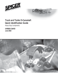
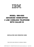
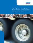
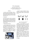
1
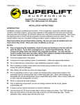
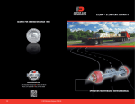
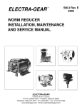
TECHNICAL
PROCEDURE
HENDRICKSON TRAILER AXLES
SUBJECT: Service Procedures
LIT NO: L1061
DATE: January 2009
TABLE OF CONTENTS
INTRODUCTION . . . . . . . . . . . . . . . . . . . . . . . . . . . . . . . . . . . . . . . . . . . . . . . . . . . . . . . . . . . . . . . . . .2
SAFETY PRECAUTIONS . . . . . . . . . . . . . . . . . . . . . . . . . . . . . . . . . . . . . . . . . . . . . . . . . . . . . . . . . . . . .3
AXLE IDENTIFICATION . . . . . . . . . . . . . . . . . . . . . . . . . . . . . . . . . . . . . . . . . . . . . . . . . . . . . . . . . . . . . .4
AXLE INSTALLATION . . . . . . . . . . . . . . . . . . . . . . . . . . . . . . . . . . . . . . . . . . . . . . . . . . . . . . . . . . . . . . .9
TRAILER AXLE ALIGNMENT . . . . . . . . . . . . . . . . . . . . . . . . . . . . . . . . . . . . . . . . . . . . . . . . . . . . . . . . .10
GENERAL WELDING RECOMMENDATIONS . . . . . . . . . . . . . . . . . . . . . . . . . . . . . . . . . . . . . . . . . . . . . . .11
WHEEL BEARINGS . . . . . . . . . . . . . . . . . . . . . . . . . . . . . . . . . . . . . . . . . . . . . . . . . . . . . . . . . . . . . . .13
RECOMMENDED BRAKE ADJUSTMENT PROCEDURE . . . . . . . . . . . . . . . . . . . . . . . . . . . . . . . . . . . . . . .15
BRAKE DISASSEMBLY / ASSEMBLY . . . . . . . . . . . . . . . . . . . . . . . . . . . . . . . . . . . . . . . . . . . . . . . . . . . .16
WELDING ABS WHEEL SPEED SENSOR BLOCKS . . . . . . . . . . . . . . . . . . . . . . . . . . . . . . . . . . . . . . . . . .18
TORQUE SPECIFICATIONS . . . . . . . . . . . . . . . . . . . . . . . . . . . . . . . . . . . . . . . . . . . . . . . . . . . . . . . . . .19
SUGGESTED PREVENTATIVE MAINTENANCE . . . . . . . . . . . . . . . . . . . . . . . . . . . . . . . . . . . . . . . . . . . . .19
HENDRICKSON TRAILER AXLE SERVICE PROCEDURES
HN (D22) Straight Axle
HN (D22) Bent or Drop Center Axle
INTRODUCTION
Hendrickson presents this publication to aid in
understanding the Hendrickson Trailer Axle and its
application requirements. Hendrickson Trailer Axles
are engineered to meet the demanding requirements
of the industry and incorporate the latest design
and manufacturing technologies. This manual is
provided to help maintain the safety, dependability
and performance designed into Hendrickson trailer
products. Read this manual carefully before you
perform installation or maintenance procedures.
CAUTION: Indicates hazards or unsafe
practices which could result in
damage to machine or minor
personal injury.
NOTE: Indicates that you must do something in order
for the axle or brake to function properly.
If you have any questions about this manual or its
instructions, contact Hendrickson Trailer Suspension
Systems at 1-866-RIDEAIR (743-3247).
You will find DANGER, WARNING, CAUTION and
NOTE symbols and statements throughout this
manual.
DANGER:
INDICATES IMMEDIATE HAZARDS
WHICH WILL RESULT IN SEVERE
PERSONAL INJURY OR DEATH.
WARNING: INDICATES HAZARDS OR UNSAFE
PRACTICES WHICH COULD RESULT
IN SEVERE PERSONAL INJURY OR
DEATH.
2
L1061
HENDRICKSON TRAILER AXLE SERVICE PROCEDURES
SAFETY PRECAUTIONS
WARNING: BEFORE PERFORMING ANY
MAINTENANCE OR REPAIR WORK
REQUIRING RAISING OF VEHICLE,
ENSURE VEHICLE IS PROPERLY
SUPPORTED WITH LIFT STANDS OF
SUFFICIENT RATED CAPACITY. DO
NOT RELY ON JACKS ALONE FOR
SUPPORT OF VEHICLE.
WARNING: SAFETY GLASSES SHOULD BE WORN
AT ALL TIMES WHEN ASSEMBLING
OR DISASSEMBLING AXLES AND
THEIR COMPONENTS.
WARNING: A SERIOUS OR FATAL INJURY CAN
OCCUR IF YOU...
• LACK PROPER TRAINING
• FAIL TO FOLLOW PROPER
PROCEDURES
• DO NOT USE PROPER TOOLS
AND SAFETY EQUIPMENT
• ASSEMBLE AXLE COMPONENTS
IMPROPERLY
• USE INCOMPATIBLE AXLE
COMPONENTS
• USE AXLES OR AXLE
COMPONENTS IN A NONAPPROVED APPLICATION
WARNING: THIS MANUAL CONTAINS DETAILED
SAFETY INSTRUCTIONS. READ,
UNDERSTAND AND FOLLOW THIS
MANUAL.
• GET PROPER TRAINING
• LEARN AND FOLLOW SAFE
OPERATING PROCEDURES
• USE PROPER TOOLS AND
SAFETY EQUIPMENT
• USE PROPER COMPONENTS
THAT ARE IN GOOD CONDITION
L1061
3
HENDRICKSON TRAILER AXLE SERVICE PROCEDURES
AXLE IDENTIFICATIONS
Standard Hendrickson Trailer Axles are available
in various spindle and tube combinations and are
designed for on-highway use. Axles are available
in straight, drop- or raised-center axles and can be
ordered fully dressed with hubs and brake drums (as
shown in figures). Other miscellaneous components
such as slack adjusters, air chambers, cam tubes,
etc. can also be specified.
Straight Axle
Drop-center Axle or Raised-center axle
STANDARD PRODUCT OFFERINGS
The part number, a description, and a serial number
are all imprinted on a tag that is attached to the axle
beam center (as shown in figure 1). The part number
is used to identify the axle specifications. This
number should be referred to when contacting
Hendrickson to determine the appropriate service
parts. The serial number is used to identify a
particular axle along with all of the component parts
as specified by the customer at the time of order. The
axle description serves as a generic description of the
axle assembly and can be used to determine some
specific axle configuration parameters.
Axle ID•Tag
Figure 1
4
L1061
HENDRICKSON TRAILER AXLE SERVICE PROCEDURES
INTERPRETING TRAILER AXLE PART NUMBERS
D22
AX
5
0
3
AXXXX
Axle Model and Spindle Type
Application Specific
Axle Type
Wheel-End Configuration
Wall Thickness
Seventh Digit
AXLE MODEL AND SPINDLE TYPE
•
•
•
•
•
•
•
•
•
•
WHEEL-END CONFIGURATION
A45 - Tapered spindle, solid bar
A65 - Tapered spindle, solid bar
D10 - Tapered spindle
D22 (HN) - Tapered spindle
K22 - Tapered spindle, press-up
S22 - Tapered spindle, solid bar
K30 - Tapered spindle, press-up
S30 - Tapered spindle, solid bar
P22 (HP) - Proper style spindle
T24 - Drive axle / Truck spindle
• 0 - With spider / flanges, no brakes, hubs or
drums
• 1 - With brakes, hubs and drums
• 2 - With spiders / flanges and hubs, no brake
drums
• 3 - With brakes, no hubs or drums
• 4 - With hubs, no spiders / flanges or brakes
• 5 - No spiders / flanges, brakes, hubs or drums
NINTH DIGIT
• A - Assemble to order options are picked at the
time of placing the axle order. Options include
brake shoe lining, ABS sensor installation and
brand selection. Assemble to order options are
for double anchor pin (DAP) axles only.
AXLE TYPE
• AX - Straight axle
• AU - Bent-tube (drop-center) axle
• AD - Straight axle, air disc brake
WALL THICKNESS
•
•
•
•
•
•
•
1
2
3
5
6
7
8
-
TENTH DIGIT UP
Stub axle (an axle cut in half) right
Stub axle (an axle cut in half) left
Stub axle (an axle cut in half) ambidextrous
1
/2" wall thickness, 5.00" OD
5
/8" wall thickness, 5.00" OD
3
/4" wall thickness, 5.00" OD
Solid bar
• Axle specific - Numbers are sequential and are
used to record the bill of material for each axle
SEVENTH DIGIT
•
•
•
•
•
•
•
•
L1061
0 - Standard trailer axle
1 - iPAC suspension axle, no longer used
2 - AdVANtage suspension axle
5 - Nominal 1/2" wall stub axle
6 - Nominal 5/8" wall stub axle
7 - Nominal 3/4" wall stub axle
8 - Machined from solid bar stub axle
H - 5/8" HD wall
5
HENDRICKSON TRAILER AXLE SERVICE PROCEDURES
INTERPRETING TRAILER AXLE DESCRIPTORS
D22
FC
167
W
NH
A
Axle Model and Spindle Type
Air Chamber
Brake Shoe Type
Wheel-end Type
Brake Size
Spider Type
AXLE MODEL AND SPINDLE TYPE
•
•
•
•
•
•
•
•
•
•
BRAKE SIZE
A45 - Tapered spindle, solid bar
A65 - Tapered spindle, solid bar
D10 - Tapered spindle
D22 (HN) - Tapered spindle
K22 - Tapered spindle, press-up
S22 - Tapered spindle, solid bar
K30 - Tapered spindle, press-up
S30 - Tapered spindle, solid bar
P22 (HP) - Proper style spindle
T24 - Drive axle / Truck spindle
•
•
•
•
•
•
•
•
•
•
•
•
•
•
•
•
•
•
BRAKE SHOE TYPE
•
•
•
•
•
•
•
•
•
CS - Cast shoe
FB - Fabricated, bolted lining
FC - Fast change fabricated
FCXX - Fast change Xtra Life II
FT - Fabricated, tapered
N - No brakes, flanges spiders
NBW - No brakes, with spiders
NB - No brakes, with flanges
ADB - Air disc brakes
123 - 121/4" X 3"
1235 - 121/4" X 31/2"
1250 - 121/4" X 5"
1255 - 121/4" X 51/2"
1275 - 121/4" X 71/2"
153 - 15" X 3"
154 - 15" X 4"
155 - 15" X 5"
157 - 15" X 7"
1586 - 15" X 85/8"
165 - 161/2" X 5"
166 - 161/2" X 6"
167 - 161/2" X 7"
1680 - 161/2" X 8"
1686 - 161/2" X 85/8"
1610 - 161/2" X 10"
187 - 18" X 7"
208 - 20" X 8"
SPIDER TYPE
• B - Bolt-on
• F - Flanges only (for bolt-on)
• W - Weld on
WHEEL-END TYPE
•
•
•
•
•
•
•
•
•
•
•
NH - No hub or wheel
W - Cast spoke wheel
WD - Cast spoke wheel and drum
B6 - 6 stud 83/4 BC hubs
B8 - 8 stud 61/2 BC hubs
B10 - 10 stud 111/4 BC hubs
B13 - 10 stud 133/16 BC hubs
B18 - 10 stud 83/4 BC hubs
SW6 - 6 stud 83/4 BC hubs
SW8 - 8 stud 61/2 BC hubs
SW10 - 10 stud 111/4 BC hubs
AIR CHAMBER
• A - Air chambers mounted on axle
6
L1061
HENDRICKSON TRAILER AXLE SERVICE PROCEDURES
In general, the TRLAXLE product will allow all of the
same standards and options currently available on
INTRAAX, such as:
TRLAXLE MODEL NUMBERS
In June 2008, Hendrickson announced the
implementation of a new configuration system for
nonintegrated trailer axles called TRLAXLE. Your
customer service representative will be able to
create a TRLAXLE model number and provide a
price on most HN (D22) and HP (P22) axles
when you send in your completed Axle Ordering
Guide (L964) or Electronic Axle Ordering Guide
(E964). Other specialty axles (drop- or raisedcenter axles, A45/A65, K22/K30, D10/D21 and T24)
will continue to use their current model number designations, like D22AU603A2-2 or K30AX603A22-2.
• Hendrickson proprietary wheel-end packages:
HVS (3-year limited warranty), HLS (5-year
limited warranty) and HUS® (7-year limited
warranty)
• TIREMAAX® CP and EC
• Brake sizes, plus 121/4" × 71/2", 121/4" × 51/2"
and 121/4" × 5"
• Brake lining options
In addition to a new TRLAXLE model number,
Hendrickson made the axle description more
meaningful. Below is a guideline for interpreting
the new description of your TRLAXLE model number.
Newly created, non-configurable axle specs and
specialty axles will also adopt this new description
logic. The following page gives an explanation of
all the new axle description codes.
Most HN and HP axle specs will be converted to
new TRLAXLE.### model numbers. In most cases,
the TRLAXLE bill of material will be identical to the
D22 or P22, except with following component
changes, if applicable:
• Stemco Guardian or Voyager will be the
standard seal replacing Chicago Rawhide
• Abex 3030-197 brake lining will become
the standard brake lining; Spicer Silver
Supreme and Haldex brake linings are
being discontinued
• Hendrickson's patented axle filter will
become standard on all axles
• New configurations will require specifying (1)
slacks only, (2) both slacks and chambers or
(3) neither slacks or chambers; we cannot
configure chambers only
• ABS sensors on drum brake specs will be
90 degrees, not straight
• ABS sensors on air disc brake specs will
be straight, not 90 degrees
• Castellated nuts will not be configurable
and must be ordered separately
Model Number: TRLAXLE.13
L1061
7
Dust Shields
RTR Lube
RTR Packages
Brake Adjusters
Chambers
ABS Option
Cam Length
Cam Option
Brake Size
Brake Type
Spider Type
Auto Lube
Tire Inflation
Axle
Track
Tube Wall
Tube Size
Axle Type
HN- S 50 5 - 0774 - W F 1670 L - S H M 1-C O Spindle
DESCRIPTION:
HENDRICKSON TRAILER AXLE SERVICE PROCEDURES
HENDRICKSON AXLE DESCRIPTION MATRIX
Spindle
HN - Tapered Spindle
HP - Parallel Spindle (Pro-Par Type)
P90 - HUS Unitized
Axle Type
S - Straight
U - Bent
C - Cambered
H - Half / Stub
Tube Size
50 - 5" Round
56 - 53/4"" Round
Tube Wall
4 - 1/2" Nominal
5 - 5/8" Nominal
H - 5/8" Nominal (Heavy Duty)
6 - 3/4" Nominal
0 - Solid Bar
Tire Inflation
T - TIREMAAX® or TIMS
P - MTIS / PSI Prepped
V - Axle Vent Only
3 - 3-Hole Prep Only
M - Military Set-up
- (Dash) - None
Axle Track
### - Track Length (inches) 1st 3 Digits
# - Track Length (1/8") 4th Digit
Auto Lube
L - Lube System - Fittings Installed
- (Dash) - None
Spider Type
B - Bolt-on Spider
F - Flange Only
W - Weld-on Spider
T - Torque Plate for Air Disc Brake
- (Dash) - No Spider / No S-Cams
Brake Type
B - B-Lock
S - Single Anchor Pin (SAP) Service Only
F - Std. Service - Dual Anchor Pin (DAP)
P - Pin Style
X - HXS / XLII - Dual Anchor Pin (DAP)
D - Air Disc Brake
- (Dash) - No Brake Shoes
Brake Size
1250 - 121/4" × 5" Brakes
1255 - 121/4" × 51/2" Brakes
1274 - 121/4"" × 71/2" Brakes
1585 - 15" × 85/8" Brakes
1650 - 161/2" × 5" Brakes
1670 - 161/2" × 7" Brakes
1685 - 161/2" × 85/8" Brakes
1610 - 161/2" × 10" Brakes
1870 - 18" × 7" Brakes
2080 - 20" × 8" Brakes
430_ - 430mm Air Disc
16N_ - 161/2" Spider Only
15N_ - 15" Spider Only
12N_ - 121/4" Spider Only
---- (4 Dashes) - No Brakes
Cam Length
S - Std. Short Length (175/8")
M - Std. Medium Length (205/8")
L - Std. Long Length (233/4")
X - Special Length (Non-Std.)
- (Dash) - No S-Cams
Cam Option
C - Cam Tube
B - RM Cartridge Bushing
- (Dash) - No Special Cam Options
ABS Option
B - ABS Mounting Bracket Only
S - ABS Sensor Installed
- (Dash) - No ABS Sensors / Brackets
8
Brake Adjusters
B - Bendix
G - Gunite
H - Haldex
- (Dash) - No Brake Adjusters
Chambers
B - Bendix
H - Haldex
M - MGM
K - Knorr - Air Disc Brake Only
- (Dash) - No Chambers
RTR Packages
1 - 10-stud, hub-piloted - 1st Digit
6 - 6-stud, hub-piloted - 1st Digit
8 - 8-stud, hub-piloted - 1st Digit
- (Dash) - No Hubs - 1st Digit
V - HVS 3-yr. - 2nd Digit
L - HLS 5-yr. - 2nd Digit
U - HUS 7-yr. - 2nd Digit
P - ConMet PreSet - 2nd Digit
- (Dash) - No RTR or 1-yr. Std. Service 2nd Digit
- (Dash) - No Drums - 3rd Digit
C - Cast Drum - 3rd Digit
F - Fused Drum - 3rd Digit
315 - 3-spoke, 15" wheel - all 3
520 - 5-spoke, 20" wheel - all 3
622 - 6-spoke, 22" wheel - all 3
624 - 6-spoke, 24" wheel - all 3
Digits
Digits
Digits
Digits
RTR Lube
G - Grease
F - Syn. Semi-Fluid Grease
O - 80 / 90 Oil
S - SAE 50
- (Dash) - None
Dust Shields
D - Dust Shield Included
- (Dash) - None
L1061
HENDRICKSON TRAILER AXLE SERVICE PROCEDURES
AXLE INSTALLATION
To ensure safe operation and maximum durability
on parts such as brakes linings and tires, it is
necessary to position and install the axle properly.
It is recommended that the axle assembly be
installed so the cams rotate in the same direction
as the wheels (see figure 2).
TOP-CENTER HOLE
AXLE
TOP-CENTER
HOLE
WHEEL ROTATION
CENTERLINE
Figure 3
Cam and wheels rotate in the same direction
Figure 2
AXLE REPAIR
Installation in which the camshaft rotation is opposite
that of the wheel rotation could cause noisy brakes,
chatter and wheel “hop”. With this is mind, the axle
should be ordered with the placement of air chamber
and slack adjuster assemblies that will ensure the
correct directional rotation of the cams when the axle
is installed.
WARNING ANY AXLE FOUND WITH CRACKS
SHOULD NOT BE REPAIRED, BUT
REPLACED IMMEDIATELY. REPAIR
WELDING CAN BE DETRIMENTAL TO
THE STRUCTURAL INTEGRITY OF THE
AXLE BEAM, WHERE THE BENEFIT OF
THE ORIGINAL TUBE HEAT
TREATMENT MAY BE NULLIFIED BY
THE WELDING. AN AXLE SHAFT
WEAKENED BY WELDING COULD
FAIL AND CAUSE AN ACCIDENT,
WHICH COULD RESULT IN SERIOUS
INJURY OR DEATH.
Unless otherwise specified by the customer,
Hendrickson Trailer Axles are manufactured without
camber. If the axle is cambered, the top dead center
of the axle will have a small die mark on each end of
the axle close to the inboard side of the brake spider
(see figure 3).
NOTE: Cambered axles must be installed with the die
marks in the top center center position
It is the responsibility of the axle installer to adjust
the brakes properly. See the recommended brake
adjustment procedure covered in this manual.
L1061
9
HENDRICKSON TRAILER AXLE SERVICE PROCEDURES
TRAILER AXLE ALIGNMENT
RECOMMENDED ALIGNMENT SPECIFICATIONS
Remove tire
Proper preparation is a must for effective axle
alignment. The vehicle, tools, equipment and work
site must all be appropriate for axle alignment. The
process also requires a trained technician using the
correct specifications.
A
I. VEHICLE PREPARATION
B
C
American Trucking Associations Technology and
Maintenance Council (TMC) RP 708, Trailer Axle
Alignment, addresses all the steps needed to make
the trailer ready for alignment.
To review these:
A-B
C-D
1/8"
1/16"
D
Remove tire
Figure 4
ALIGNMENT
Axles should be adjusted to an alignment of no more
than 5 MOA scrub with the true center of the trailer
frame if it is a single axle. If the trailer has multiple
axles, each axle should be adjusted to not more
than 2.5 MOA scrub relative to the front (or reference)
axle. (This adjustment was previously stated as a
difference of not more than 1/16 inch between the right
and left centers of adjacent angles).
1. Inspect the suspension and axles for any
obvious damage.
2. Tighten, repair or replace, as needed, any
parts that do not meet suspension or axle
manufacturer criteria for serviceability.
3. Check tires for proper inflation and matching
diameters.
CAMBER
4. Park the trailer on a smooth and level pad with
the parking brakes released.
Typical trailer axles exhibit 23-29 MOA of TOTAL
camber change from an off-ground free state to
a fully loaded condition. Cambered axles are
engineered to flex to a straight beam under load.
New Hendrickson Trailer Axles may be cambered by
special order with 33 MOA of positive camber. This
allows the vertical axis through the tire to return to
near “plumb” condition when loaded.
NOTE: After backing the trailer in, pull it forward 10
feet to a gentle stop. This will allow
suspension parts to settle in a “forward
running” position. Use wheel chocks to prevent
injury due to accidental movement of the
trailer.
III. ADJUSTMENTS
5. With the brakes still released, adjust the height
control valve for the proper setting and the upper
coupler to the proper height by raising or
lowering the landing gear legs.
All fasteners should be loosened prior to measurements and adjustments. This reduces disturbances
to the measuring equipment. All adjustments to axle
alignment should be made by first moving the axle
toward the rear or the trailer — past the intended
point. This step assures that any free motion in the
system is placed in a “draft” condition.
6. DO NOT proceed unless the wheel bearing end
play is known to be in adjustment per TMC, the
bearing manufacturer and / or this manual.
II. SPECIFICATIONS
Repeated difficulty in adjusting the axle to the desired
reading is most often due to a loose wheel bearing,
badly worn suspension component or a combination.
Axle alignment specifications may be stated in
inches, degrees, minutes of angle (MOA or 1/60th
of a degree) or m/M. Each format can produce
equivalent results. Hendrickson Trailer Axles are built
to less than +/- 2.5 MOA run out at each spindle.
WARNING NEVER BEND THE AXLE, BY ANY
MEANS, IN ORDER TO CORRECT
ANY ALIGNMENT CONDITION.
THIS COULD WEAKEN THE AXLE
AND CAUSE AXLE FAILURE WHICH
COULD RESULT IN SERIOUS INJURY
OR DEATH.
TOE-IN / TOE-OUT
Installed axles should measure no more than 8 MOA
toe-in and 4 MOA toe-out.
10
L1061
HENDRICKSON TRAILER AXLE SERVICE PROCEDURES
GENERAL WELDING
RECOMMENDATIONS
In welding suspension component parts to a
Hendrickson Trailer Axle, extreme care must be
exercised to obtain their correct location and to
ensure the spring seated load bearing surfaces are
parallel to each other. Any welding of additional
attachments to the axle should be approved by the
Hendrickson trailer product engineering department
to maintain warranty coverage.
The arc should not be broken at the end of each pass
and the corners should be wrapped. The electrode
should be backed up to fill in the filler crater at the
end of each pass. Thoroughly clean the weld
between each pass.
It is necessary when welding to avoid the high stress
areas on the tube top (compression zone) and tube
bottom (tension zone). All welds should be made as
close to the horizontal centerline as possible. When
the axle tube is subjected to the heat from welding
and then rapid cooling, the material adjacent to the
weld loses its desirable ductile properties and
becomes brittle. If this condition exists in the high
stress areas under maximum load conditions, the
life of the axle will be greatly reduced and premature
fatigue failure can occur. Recommended locations
for the welds are shown below in figure 5.
CAUTION
Do not bring axles in from nonheated storage and weld while cold.
CAUTION
To provide optimum suspension-totube welds, preheating is
recommended. Preheating will
minimize loss of ductile properties in
the weld area by slowing the rate of
cooling, thus reducing the formation
of an untempered martensitic grain
structure adjacent to the weld.
Martensite, a brittle grain structure,
is formed by the rapid cooling of the
metal surrounding the weld area.
Preheat the suspension seat weld
area to 500 to 600° Fahrenheit with
a rosebud prior to welding. Preheat
temperature should be verified with
a temperature sensitive crayon or
other appropriate means.
CAUTION
Do not “test the arc” on the axle
beam.
Weld placement recommendations
for suspension bracketry
N O WELD
ZO N E
3 .0 0
Max
HARDWARE FIT
2.00" M
Avoid excessive welding. Fit the seat / hardware as
close as possible to the axle. The gap should not
exceed 1/8 inch see Figure 6.
AX.
1 . 5 0"
"
1/8" M
4 .0 0
N O WELD Z O NE
AX.
Figure 5
The welding
rods should conform to American Welding Society
(AWS), grade E-7018 (Oven-dried) or comparable.
Recommended rod size is 5/32 inch at
voltage and amperage recommended by the electrode
manufacturer. For maximum strength, a three-pass
weld should be used.
L1061
C O RREC T
INC O RREC T
Figure 6
11
HENDRICKSON TRAILER AXLE SERVICE PROCEDURES
WELDING METHODS
Table 1 lists four methods that may be used to weld
hardware to trailer axles. The weld tensile strength
must be 70,000 psi per AWS specifications.
(1) Tack weld
(1) T side
AC K WELD
each
NoO tack
N
TAC K
welds
W
ELDS at
AT
Tthe
HEends
ENDS
EAC H SIDE
TABLE 1
METHOD FOR WELDING
CARBON AND LOW
ALLOY STEELS
Shielded Metal Arc
(stick electrodes)
Gas Metal Arc
(MIG, solid wire feed)
Gas Tungsten Arc
(TIG) has non-consumable
electrode (use stick electrodes)
Flux Cored Arc
(self shielded wire)
AWS ELECTRODE
CLASSIFICATION
AWS
SPEC
E70XX
ER70S-X
A5.1
A5.5
A5.18
ER70-X
A5.18
E70T-X
A5.20
Figure 7
NOTE: For maximum strength, a three-pass weld
should be used. All final welds should be
made in one continuous pass. The arc should
not be broken at the end of each pass and the
corners should be wrapped.
WELDING HARDWARE TO AXLE
NOTE: TO PREVENT AXLE DISTORTION:
• Alternate welds between the front and rear of
the bracket.
CAUTION • The axle installer should obtain
and read a copy of the suspension
manufacturer’s installation
instructions.
• Alternate welds between the roadside bracket
and curbside bracket.
• Only use operators certified by
AWS.
This welding recommendation pertains to all
Hendrickson tubular axles. Unapproved variation
from the procedures listed will void the axle warranty
and could result in an unsafe weld. In the case of
an uncertain circumstance, the Hendrickson Trailer
Products Engineering Department should be
contacted at 1-800-RIDEAIR (743-3247).
• The axle and its mating bracket
must be at 60 degrees minimum
and free of moisture, dirt, scale,
paint and grease. Do not bring in
axles from non-heated storage and
weld while cold.
• Prevent bearing damage. When
grounding welding equipment to the
axle, prevent current from passing
through the wheel bearings.
TACK WELDING BRACKET TO AXLE:
NOTE: Do not place tack welds at what will be the
ends of the final weld. Tack weld all brackets
onto axle before fusing these tack welds into
final welds. Thoroughly clean the slag from the
tack welds before applying the final welds
(see figure 7).
12
L1061
HENDRICKSON TRAILER AXLE SERVICE PROCEDURES
WHEEL BEARINGS
OIL LUBRICATED WHEEL ENDS
GREASE LUBRICATED WHEEL ENDS
Oil should be changed at least every 100,000 miles
or once a year and whenever the seals or brakes are
replaced. Oil level should be inspected every 1,000
miles. Always allow a few minutes after adding oil
or vehicle operation for the oil to settle, when
establishing the required oil level.
Grease should be replaced if contaminated or if the
hub is removed from the spindle. For normal service,
grease should be replaced annually or at 100,000
mile intervals. For severe or off-highway service,
grease should be replaced semi-annually or at
30,000 mile intervals. Bearings should be packed
by machine or by hand methods to ensure grease
is forced into the cavities between the rollers, cone
and cage of the bearings. The wheel and hub cap
should be filled with grease when reassembling.
SUGGESTED OIL PROPERTIES
Petroleum based or synthetic oils that meet or exceed
military specification MIL-L-2105D and American
Petroleum Institute (API) service classification GL-1
through GL-5 are the minimum requirements for use
in Hendrickson Trailer Axles.
SUGGESTED GREASE PROPERTIES
The table below recommends the NLGI-2 grade of
grease under normal loading and operating speeds
of 100 -1000 rpm. For heavy loads and low speeds,
the advice of a lubrication engineer should be
obtained.
The table below indicates which SAE viscosities are
recommended for various temperature ranges the
vehicle will encounter.
GREASE GUIDE
SAE 140
SAE 85W-140
SAE 90
SAE 80W-140
SAE 80W
SAE 75W-140
SAE 75W-90
SAE 75W
C -40
-26
-12
0
+4
+15
+27
+38
F -40
-15
-10
+32
+40
+60
+80
+100 F
NLGI
GREASE
GRADE
#1
#2
NOTE
Use in Extreme Cold
Normally Preferred
SEMI FLUID
SYNTHETIC
GREASE TYPE
Mobilith 007
or equivalent
NLGI
GREASE
GRADE
#00
NOTE
Normally Preferred
C
WARNING DO NOT MIX LITHIUM, CALCIUM,
SODIUM OR BARIUM COMPLEX
GREASES DUE TO POSSIBLE
COMPATIBILITY PROBLEMS. WHEN
CHANGING FROM ONE TYPE OF
GREASE TO ANOTHER, IT IS
NECESSARY TO ENSURE THAT ALL
THE OLD GREASE HAS BEEN
REMOVED.
Ambient air temperature
WARNING DO NOT MIX MOTOR OIL WITH EP
GEAR OIL DUE TO POSSIBLE
COMPATIBILITY PROBLEMS.
WARNING FAILURE TO CORRECTLY LUBRICATE
BEARINGS AND TO MAINTAIN
PROPER LUBRICATION COULD
CAUSE BEARING AND AXLE SPINDLE
DAMAGE, WHICH COULD RESULT IN
THE WHEEL LOCKING UP OR
COMING OFF DURING VEHICLE
OPERATION.
L1061
SOAP BASED
GREASE
TYPE
Calcium Complex
Lithium Complex
13
HENDRICKSON TRAILER AXLE SERVICE PROCEDURES
WHEEL BEARING ADJUSTMENT
PROCEDURE
7. Install the outer spindle nut. Using a torque
wrench, tighten this nut to 300-400 ft. lbs.
Resulting end play should be .001 to .005
inch.
DOUBLE NUT ARRANGEMENT
1. Prior to installing any wheel-end fasteners,
make sure the spindle area is free of dirt and
debris. As well, make sure all nuts and
washers are free of dirt. Clean mating
surfaces are important for proper wheel-end
assembly.
NOTE: If end play is not .001 to .005 inch,
disassemble and repeat this procedure
WARNING FAILURE TO TORQUE THE OUTER
LOCK NUT PROPERLY COULD CAUSE
THE WHEEL TO COME OFF DURING
VEHICLE OPERATION, WHICH
COULD RESULT IN PROPERTY
DAMAGE, SERIOUS INJURY OR
DEATH.
2. After properly installing the bearing cones
and wheel-end seal onto the spindle and
sliding the wheel end onto the spindle,
tighten the inner spindle nut with a torque
wrench to 150-200 ft. lbs. to set the
bearings and wheel end.
CAUTION
WARNING IF AN EXTERNAL TANG OR
SETSCREW TYPE LOCK WASHER IS
USED, IT IS IMPORTANT TO
REMEMBER TO BEND THE TABS
OVER THE OUTER LOCK NUT, OR TO
INSTALL THE SET SCREWS IN THE
LOCK WASHER AFTER THE OUTER
NUT HAS BEEN TORQUED. FAILURE
TO FOLLOW THIS PROCEDURE
COULD RESULT IN PROPERTY
DAMAGE, SERIOUS INJURY OR
DEATH.
Do not use an air impact wrench to
tighten this nut.
3. Loosen this inner nut to allow the brake drum
to rotate freely. Backing off one (1) full turn
is recommended.
4. Retighten the inner spindle nut to 50 ft. lbs.
by hand using a torque wrench to position
the bearings for final adjustment.
CAUTION
Do not use an air impact wrench to
tighten this nut.
Periodic inspection and regular replacement of
lubricant is important to obtain maximum bearing
life. Always inspect bearings for damage prior to
installation. When installing wheel bearings, it is
important to ensure both the inside of the wheel hub
and bearings are clean. Hendrickson recommends
that seals be replaced when wheels are removed.
Extreme care should be taken when reinstalling
wheels to prevent damage to the seals.
5. Back the inner spindled nut off 1/4 turn.
6. Install the retaining fastener or fasteners
onto the spindle according to the fastener
used. If washers are used, be sure they are
facing in the right direction and are clean.
Make sure any washers with dowels fit
properly into the mating holes.
SPECIFICATIONS
AXLE LOCATION SPICER BEARING
MODEL
CUP NUMBER
D22
Inner
M10HA102
D22
Outer
M10HA103
P22 Inner/Outer
M10HA116
SPICER BEARING
CONE NUMBER
M10HB100
M10HB101
M10HB119
INDUSTRY STD.
CUP NUMBER
HM218210
HM212011
HM518410
14
INDUSTRY STD.
CUP NUMBER
HM218248
HM212049
HM518445
WIDTH
OUTSIDE
DIAMETER
1.575"
5.787"
1.500"
4.813"
1.563"
6.00"
INSIDE
BORE
3.542"
2.625"
3.501"
L1061
HENDRICKSON TRAILER AXLE SERVICE PROCEDURES
RECOMMENDED BRAKE
ADJUSTMENT PROCEDURE
a. Optimum pushrod travel on a
green brake should be under 2
inches
CAUTION Failure to properly adjust brakes
could cause reduced braking
performance.
b. Optimum pushrod travel on a
burnished or broken-in brake should
be under 13/4 inches
1. Grease cam bracket and spider fittings prior
to brake shoe installation.
B. Check the angle between the brake
adjuster and pushrod. With the brakes
applied, the angle should be 90 degrees
+/- 5 degrees
WARNING CARE MUST BE EXERCISED TO
PREVENT GREASE SPACING FROM
COMING IN CONTACT WITH BRAKE
LININGS WHICH COULD CAUSE A
REDUCTION IN BRAKING
PERFORMANCE. REDUCED BRAKING
PERFORMANCE COULD CAUSE AN
ACCIDENT RESULTING IN SERIOUS
INJURY OR DEATH.
CAUTION When automatic brake adjusters are
used, it is necessary to follow the
installation and adjustment
procedure recommended by the
automatic brake adjuster
manufacturer. Failure to follow the
recommended procedure could result
in improper operation of the
automatic slack adjuster, resulting in
reduced brake performance or
premature lining wear.
2. Adjust the brake adjuster until the brake
lining comes into contact with the brake
drum.
A. For green brakes* there should be a slight
amount of wheel drag at initial adjustment
to compensate for any lining irregularities
(high spots, etc)
C. For burnished brakes, apply pressure to
brakes and check for lining to drum
contact. Using a .010 inch feeler gauge,
the lining to drum contact should range
from 60 to 100 percent during brake
application
*A “green brake” is an unground, unburnished brake. There is a break-in
period where the lining will seat into a normal contact pattern with the
drum
B. For burnished or broken-in brakes, back
off the slack adjuster to achieve .010 inch
clearance between drum and shoe
D. Check to ensure the lining is inside the
drum during application. More than .060
inch protruding out of the drum is not
recommended
3. Apply brakes using normal truck operating
pressure (average line pressure should be
90 psi).
4. Rapidly release air pressure from the brakes
and confirm that all brakes quickly release to
the normal relaxed position
WARNING USE OF AIR PRESSURE EXCESS OF
130 PSI COULD RESULT IN FAILURE
OF THE AIR CHAMBER OR SPRING
BRAKE CHAMBER, WHICH COULD
RESULT IN SERIOUS INJURY OR
DEATH.
WARNING • BRAKE LININGS CONTAIN NON
ASBESTOS FIBERS
• BREATHING BRAKE DUST MAY BE
HAZARDOUS TO YOUR HEALTH AND
MAY CAUSE SERIOUS RESPIRATORY
OR OTHER BODILY HARM
A. Check the amount of push rod travel.
Maximum should not exceed 21/2 inches
for Type 30 long-stroke chambers, 2
inches for Type 30 chambers and 13/4
inches for Type 24 chambers
L1061
• AVOID CREATING DUST
• DO NOT REMOVE BRAKE DRUM
WITHOUT PROPER PROTECTIVE
EQUIPMENT.
15
HENDRICKSON TRAILER AXLE SERVICE PROCEDURES
5. Remove brake return springs.
• DO NOT WORK ON LININGS
WITHOUT PROPER PROTECTIVE
EQUIPMENT
6. Remove camshaft lock ring, spacer washer
and cam shaft.
• DO NOT REPLACE LININGS
WITHOUT PROPER PROTECTIVE
EQUIPMENT
7. Remove cam roller and shaft (in case of the
cast shoe, remove roller shaft set screw and
roller assembly) and anchor pin bushing
from shoes.
• DO NOT ATTEMPT TO SAND,
GRIND, CHISEL, FILE, HAMMER OR
ALTER BRAKE LININGS IN ANY
MANNER WITHOUT PROPER
PROTECTIVE EQUIPMENT
8. Remove anchor pin bushings, camshaft
bushing and seals from spider.
BRAKE ASSEMBLY
• FOLLOW O.S.H.A. STANDARDS FOR
PROPER PROTECTIVE DEVICES TO
BE USED WHEN WORKING WITH
BRAKE MATERIALS
1. Install new anchor pin bushings, camshaft
bushing and camshaft seals into the spider.
WARNING WHEN INSTALLING CAMSHAFT
SEALS, THE SEAL ON THE SLACK
ADJUSTER SIDE SHOULD BE
INSTALLED WITH SEAL FACING INTO
SPIDER. THIS ALLOWS GREASE TO
PURGE OUTSIDE THE BRAKE
ASSEMBLY WHEN GREASING THE
CAMSHAFT BUSHING. FAILURE TO
FOLLOW THIS PROCEDURE COULD
CAUSE GREASE TO COME INTO
CONTACT WITH BRAKE LININGS,
CAUSING BRAKE FAILURE.
WARNING IT IS CRITICAL THAT ANY BRAKE
DRUM REACHING MAXIMUM WEAR
DIAMETER, AS CAST ON DRUM, BY
TURNING, GRINDING AND / OR
WEARING BE CONSIDERED UNSAFE
AND IMMEDIATELY REPLACED. IN
ORDER TO AVOID SERIOUS INJURY
OR DEATH, ANY BRAKE DRUM
EXCEEDING THIS DIMENSION IS
CONSIDERED A SAFETY HAZARD. IF
IN DOUBT, CONTACT THE BRAKE
DRUM MANUFACTURER.
2. Install cam roller assemblies onto the brake
shoes.
BRAKE DISASSEMBLY / ASSEMBLY
3. Install the camshaft into the spider; Install
spacer washer and lock ring on cam before
sliding the cam through the camshaft support
bracket; Install the slack adjuster and the
lock ring.
BRAKE DISASSEMBLY
1. Release brakes and back off slack adjuster.
2. Remove slack adjuster lock ring and slack
adjuster.
3. Remove brake drum.
4. Remove anchor pins and brake shoes.
CAUTION
Excessive pounding on anchor pins
or cam roller pins to remove or
install them can damage the pins
and cause misalignment of the
brake spiders and brake shoes. The
use of a soft hammer or brass drift
is recommended to remove or install
the anchor pins.
16
L1061
HENDRICKSON TRAILER AXLE SERVICE PROCEDURES
WARNING WHEN REASSEMBLING BRAKES,
HENDRICKSON RECOMMENDS THAT
THE BRAKE RETURN SPRINGS BE
REPLACED WITH NEW SPRINGS TO
ASSURE PROPER OPERATION OF THE
BRAKE.
4. Install the brake return springs on the brake
shoes.
5. Position brake shoes on the spider and insert
the anchor pins.
6. If air brake chambers are replaced, the
correct mounting holes must be used to
correspond to brake adjuster length.
(see figure 8)
6" B R AK E
ADJUS T ER
(A-A H O LES)
5 1/2"
BR AK E ADJUS T ER
(A-B H O LES)
5" B R AK E
ADJUS T ER
(B-B H O LES)
Figure 8
7. Connect slack adjuster to brake chamber
pushrod
8. Adjust brakes as outlined in brake
adjustment procedures
NOTE: To ensure brakes meet F.M.V.S.S. 121
performance requirements, Hendrickson
recommends that only original equipment
brake components be used.
Any questions or comments on the above procedure
should be directed to the Hendrickson trailer
engineering department.
L1061
17
HENDRICKSON TRAILER AXLE SERVICE PROCEDURES
WELDING ABS WHEEL SPEED SENSOR BLOCKS
12
11
TONEOR
EXC IT ER R ING
1
WHEEL HUB
10
2
S PEED S ENSO R
MO UNT ING B LO C K
MO UNT SENSO R
BLO C K IN T HIS
RANGE
9
BLO C K BO RE
3
AXLE
S ENSO R BLO C K
Figure
FIG. 5 9
WELD BEAD
( ALONGBOTHSIDES )
Figure
FIG. 610
S ENSO R B LO C K
SPRING C LIP
SPRING C LIP TAB
MO UNT ING B LO C K
. 125”
TO
WELD BEAD
SPEED SENSO R
Figure
FIG. 711
. 187 ”
EXC IT ER R ING
H UB
Figure
FIG. 812
Correct installation of the speed sensor blocks is
extremely important for proper operation of the
anti-lock system. Use electric welding equipment
only to install the blocks.
3. Remove the hub and bearing assembly and
brake assembly from the axle spindle. Clean
all oil or grease from the axle spindle.
4. Install the sensor block on the fixture tool
and attach the fixture tool to the axle spindle.
1. Properly support the trailer axle using jack
stands, be sure to provide proper clearance
to be able to weld the sensor block on the
axle near the tone (exciter) ring.
5. Adjust the position of the fixture tool as
necessary to align the sensor block to the
scribed position in step 2 and tighten in
place.
2. With the hub in place, locate the sensor
mounting block at the 9 or 3 o’clock position
on the axle spindle to lessen the effect from
axle flexure due to loading (see figure 9)
manually hold the sensor block in place and
scribe its location on the axle spindle (see
Figures 10 and 12).
6. Weld the sensor block to the spindle axle;
weld along both sides of the block
(see Figure 10).
7. Remove the fixture tool and let the sensor
block cool after cool down, install the
sensor spring clip and sensor as illustrated
in Figure 11.
NOTE: The distance of the sensor block from the face
of the tone ring “teeth” must be between
.125 inch to .187 inch (see figure 12).
18
L1061
HENDRICKSON TRAILER AXLE SERVICE PROCEDURES
TORQUE SPECIFICATIONS
FASTENER SPECIFICATIONS
PART NAME
Spindle Outer Nut
Cam Brackets
Air Chamber
Mounting Bolts
Dust Shield
Mounting
Brake Lining
To Table
Hub Cap to Hub
SIZE & THREAD
2 5/8 - 16UN
5
/16 - 18 Self-tapping
5
/8 - 11 UNC
TORQUE
250 - 400 ft. - lbs.
175 - 225 in. - lbs.
100 - 115 ft. - lbs.
Self-tapping
180-200 in. - lbs.
Brass Screw
3
/8 - 24UNF
1
/14 - 20UNC
5
/16 - 18 UNC
3
/4 - 16UNF
7
/8 - 14 UNF
1 - 14 UNF
7
/16 - 14 UN
100-150 in. - lbs.
Wheel Stud
Backnut
Haldex ABA
Control Arm Nut
96-144 ft. - lbs.
144-216 in. - lbs.
175-200 ft. - lbs.
180-250 ft. - lbs.
200-300 ft. - lbs.
40-50 ft. - lbs.
SUGGESTED PREVENTATIVE MAINTENANCE
EVERY 1,000 MILES:
100,000 MILES, ONCE A YEAR OR AT BRAKE
RELINE:
Ë Check oil level in wheel hub and inspect wheel
Ë Replace wheel bearing lubricating oil
for leaks
(if applicable)
15,000 MILES OR MINIMUM OF TWICE A YEAR:
Ë Check brake air chambers and slack adjusters
Ë Check brake adjustment
Ë Inspect brake rollers, roller shafts, anchor pins
and bushings and replace if necessary
Ë Repack wheel bearings (grease application)
Ë Lubricate camshaft bushings and brake adjusters
25,000 TO 30,000 MILES:
Ë Check shoes for bent shoe ribs, cracks in shoe
table welds or ribs, and elongated rivet holes.
Replace shoes if any of these conditions exist
Ë Check lining wear and estimate replacement time;
replace with new shoes or reline when thickness
of lining is 1/4 inch at thinnest point, or 1/16 inch
about rivet or bolt head, and replace any cracked,
broken or oil-soaked linings immediately
Ë Inspect camshaft, camshaft spider bushing and
camshaft support bracket bushing for any signs of
wear
Ë Lubricate camshaft bushings and brake adjusters
Ë Inspect brake drums for heat checks, grooves, hot
spots, glazing, cracks and out-of-round
L1061
19
www.hendrickson-intl.com
Trailer Suspension Systems
250 Chrysler Drive, Unit #3
Brampton, ON Canada L6S 6B6
905.789.1030
Fax 905.789.1033
L1061 1-09
Trailer Suspension Systems
2070 Industrial Place SE
Canton, OH 44707-2641 USA
866.RIDEAIR (743.3247)
330.489.0045
Fax 800.696.4416
Information contained in this literature was accurate at the time of publication. Product changes may have been made after the copyright date that are not reflected.
© 2009 Hendrickson USA, L.L.C. (U.S. Rights) Hendrickson International Corporation (Rights Outside U.S.) All Rights Reserved
Trailer Suspension Systems
Av. Industria Automortriz #200
Parque Industrial Stiva Aeropuerto
Apodaca, N.L., México C.P. 66600
(52) 81 8288 1300
Fax (52) 81 8288 1301
Printed in United States of America