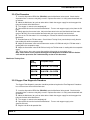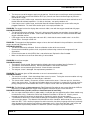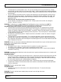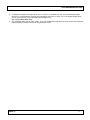
1
6526 South Cottonwood Street
Salt Lake City, Utah 84107
(801) 266-5300
Fax (801) 270-5590
Toll Free USA 1-866-4maxtec
[email protected] www.maxtecinc.com
Technical Service Manual
MaxVenturi Oxygen Delivery Device
R211M01
CONTENTS
DESCRIPTION
PAGE
SECTION 1:
1. Introduction ....................................................................................................................... 3
SECTION 2:
2. Diagnostics
2.1 Error Codes ............................................................................................................ 4
2.2 Flow diagnostic procedure ...................................................................................... 5
2.2.1 Background ......................................................................................................... 5
2.2.2 Equipment needed .............................................................................................. 5
2.2.3 Configuration ...................................................................................................... 5
2.2.4 Test procedure .................................................................................................... 6
2.2.5 Oxygen flow diagnostic procedure ....................................................................... 6
SECTION 3
3. Troubleshooting ................................................................................................................ 8
SECTION 4
4. Replacement Procedures ............................................................................................... 12
4.1 Front cover/circuit board replacement .................................................................. 12
4.2 Flow meter cleaning procedure ............................................................................ 13
4.3 Cable replacement procedure .............................................................................. 14
4.4 Valve cartridge replacement procedure ................................................................ 16
4.5 Orifice leak detection procedure ........................................................................... 17
4.6 Orifice replacement procedure ............................................................................. 17
4.7 Battery replacement procedure ............................................................................ 19
4.8 Conic replacement procedure............................................................................... 20
SECTION 5
5. Spare and replacement parts .................................................................................... 20-21
REV. F
2
INTRODUCTION
1. INTRODUCTION
NOTICE
Repair of this equipment must be performed by a qualified service technician experienced in
repair of portable hand-held medical equipment. The MaxVenturi series of products has been
designed for maximum reliability, stable performance and low maintenance.
Send Maxtec products/material in need of factory repair to:
Maxtec
Customer Service Department
6526 South Cottonwood Street
Salt Lake City, Utah 84107
(Include RMA number)
Maxtec Customer Service Line: 1-800-748-5355
HOW TO USE THIS MANUAL
This manual provides service technicians with information needed to maintain and service the
MaxVenturi series of products. The manual is divided into several sections. The DIAGNOSTICS
section describes self-test and service diagnostics for checking system functions. The
TROUBLESHOOTING section provides a guide to assist service technicians in locating the
source of problems. The REPLACEMENT PROCEDURES section contains instruction for
removal and replacement of assemblies that are considered field-replaceable.
GENERAL TROUBLESHOOTING GUIDELINES
Troubleshooting the MaxVenturi series of products should always begin by assessing the problem
with the user who experienced the trouble. This may eliminate unnecessary troubleshooting
steps. Once a general problem has been identified, refer to the trouble shooting guidelines in
Section 3 to determine the proper corrective action.
After a component has been replaced, verify that the unit is operating properly by running the
appropriate diagnostic procedure.
CAUTION
The MaxVenturi contains electronic components that are susceptible to damage by electrostatic
discharge. When disassembling the device, work at a static controlled workstation; wear a static
control wrist strap to discharge accumulated static charges from you and any tool you are using.
Handle the circuit board by the case. Use antistatic containers for transporting circuit boards.
Note: Some illustrations and pictures may be for representation only. However, the repair
operations remain the same as set forth in this service manual.
REV. F
3
TROUBLESHOOTING
2. DIAGNOSTICS
2.1 ERROR CODES
The MaxVenturi series of products contains internal programming designed to indicate common
errors that occur during the use and maintenance of the device. The analyzer has a self test
feature built into the software to detect faulty calibrations, oxygen sensor failures, and low battery
voltage. When errors occur in the function of the oxygen analyzer assembly portion of the device,
error codes are displayed to signify to the end user or service technician the type of error and
corrective action(s) needed to restore proper function of the device. Listed below are the types of
error codes displayed, the types of error they may signify, and the corrective action(s) needed to
restore proper function.
E02: No signal from sensor
Possible Errors:
No sensor attached.
No signal is being sent through the cable to the analyzer.
Corrective action: Disconnect and reconnect the sensor. Unit should perform an auto calibration
and should read 20.9%. Should the unit fail to calibrate properly, see troubleshooting section of
this manual.
E03: No valid calibration data available
Possible Errors:
Calibration is occurring when oxygen levels are not at room air or 100% oxygen.
Unit is not in thermal equilibrium.
Corrective action: Make sure the unit has reached thermal equilibrium. Perform calibration as
described in user manual.
E04: Battery below minimum operating voltage.
Possible Errors:
Battery power is low.
Corrective action: Replace the batteries as described in replacement procedures section of this
manual.
CAL Err St: O2 Sensor reading is not stable.
Corrective action: Wait for displayed oxygen reading to stabilize when calibrating the device at
100% oxygen. Wait for unit to reach thermal equilibrium. (Note this can take up to one half hour if
the device is stored in temperatures outside its operating temperature range.)
CAL Err lo: Sensor voltage too low
REV. F
4
TROUBLESHOOTING
Corrective action: Repeat calibration routine as described in user manual. If unit repeats this error
more than three times, refer to troubleshooting section of this manual.
CAL Err hi: Sensor voltage too high
Corrective action: Repeat calibration routine as described in user manual. If unit repeats this error
more than three times, refer to troubleshooting section of this manual.
CAL Err Bat: Battery voltage is too low to recalibrate.
Corrective Actions: Replace batteries (See replacement procedures section 4.7.) Repeat
calibration routine to insure proper function.
2.2 FLOW DIAGNOSTIC PROCEDURE
2.2.1 Background
The MaxVenturi series of products uses the venturi effect to entrain room air by
using a stream of oxygen flowing perpendicular to the entrainment port. The output
of mixed oxygen and air can be affected by various factors – the velocity of the
oxygen exiting the orifice (affected by pressure, and orifice size), the shape and
position of the diffuser, the length and diameter of tubing attached to the exit port of
the device, the type of user interface, and the presence and type of inlet filter.
A test system was devised by Maxtec, Inc. to measure the flow characteristics of the
MaxVenturi device and to detect product failures or defects. Note: The flow
diagnostic procedure must be performed with this test system setup to ensure
correct diagnostic data.
2.2.2 Equipment Needed
• 50 psi supply source of medical grade oxygen
• TSI 4000 series flow meter – Model 4040 E – see www.tsi.com
• PC – used to fix settings of the TSI 4000 series flow meter.
• 22mm dia. corrugated tubing – 22” length.
• Flow Inspection Tool – Maxtec Part # - MT130 (MaxVenturi) HEPA filterMaxtec Part # RP34P02
2.2.3 Configuration
2.2.3.1 TSI Configuration
Using the supplied software and PC modify the settings of the TSI4000 series
flow meter to measure a mixture of oxygen and air with an oxygen
concentration of 32%. Ensure that this device is maintained at this setting for
the duration of use.
2.2.3.2 Test Bench Configuration
On the outlet port of the TSI 4000 series flow meter, attach the Flow
Inspection Tool (MT130) for the MaxVenturi. Attach the 22mm diameter
corrugate tubing onto the inlet port of the TSI4000 Series flow meter.
REV. F
5
TROUBLESHOOTING
2.2.4 Test Procedure
1. Insert the disposable HEPA filter (RP34P01) onto the MaxVenturi to be tested. Check that the
disposable filter is not excessively dirty or moist. Replace filter when it is visibly contaminated with dirt
or moisture.
2. Mount the MaxVenturi to a pole or other device. Attach the oxygen supply line to the oxygen inlet
fitting on the back of the MaxVenturi.
3. Turn oxygen % control valve completely off.
4. Open on/off valve on the back of the MaxVenturi. Turn on main oxygen supply valve (from the O2
tank).
5. Slowly open the flow control valve. Adjust the flow control valve until the MaxVenturi flow meter
reaches 20 LPM. Be sure to read the flow meter with your eyes vertically level to the ball.
6. Turn on the TSI flow meter if it is not already on. Connect the 22mm hose to the outlet of the
MaxVenturi.
7. Read the flow on the TSI flow meter. Check Venturi Testing Chart (seen below) to verify that the
flow reading falls within acceptable range.
8. Adjust the flow control valve until the flow meter reaches 35 LPM and verify the TSI flow meter is
reading within the acceptable range.
9. Adjust the flow control valve to 50 LPM and verify the TSI flow meter is reading with the acceptable
range.
10. Failure occurs when one or more flow readings fall outside the acceptable range.
Note: When failure occurs perform the Oxygen Flow Diagnostic Procedure found in Section
2.2.5 and then proceed to the Troubleshooting section of this document.
MaxVenturi Testing Chart
Flow
Setting
Acceptable Range
20 LPM
15.8 LPM – 21.0 LPM
35 LPM
28.8 LPM – 34.0 LPM
50 LPM
42.1 LPM – 47.6 LPM
2.2.5 Oxygen Flow Diagnostic Procedure
The Oxygen Flow diagnostic procedure should be performed anytime the Flow Diagnostic Procedure
has a failure at one or more of the flow rates.
1. Insert the disposable HEPA filter (RP34P01) onto the MaxVenturi being tested. Check that the
disposable filter is not excessively dirty or moist. Replace filter when it is visibly contaminated with dirt
or moisture.
2. Mount the MaxVenturi to a pole or other device. Attach the oxygen supply line to the oxygen inlet
fitting on the back of the MaxVenturi.
3. Turn oxygen % control valve completely off.
4. Open on/off valve on the back of the MaxVenturi. Turn on main oxygen supply valve
(from the O2 tank).
5. Plug the inlet of the disposable filter.
REV. F
6
TROUBLESHOOTING
6. Slowly open the flow control valve. Adjust the flow control valve until the MaxVenturi flow meter
reaches 20 LPM. Be sure to read the flow meter with your eyes vertically level to the ball.
7. Turn on the TSI flow meter if it is not already on. Connect the 22mm hose to the outlet of the
MaxVenturi.
8. Read the flow on the TSI flow meter. Check Oxygen Flow Testing Chart (seen below) to verify that
the flow reading falls within acceptable range.
9. Adjust the flow control valve until the flow meter reaches 35 LPM and verify the TSI flow meter is
reading within the acceptable range.
10. Adjust the flow control valve to 50 LPM and verify the TSI flow meter is reading within the
acceptable range.
11. Failure occurs when any flow reading falls outside the acceptable range.
*Proceed to Troubleshooting Section for further diagnosis.
MaxVenturi Oxygen Flow Testing Chart
Flow
Setting
Acceptable Range
20 LPM
2.35LPM – 2.97 LPM
35 LPM
4.26 LPM – 4.87 LPM
50 LPM
6.77 LPM – 7.38 LPM
2.2.6 MaxVenturi Leak Test Procedure
1. Attach oxygen supply line to the oxygen inlet fitting on the back of the MaxVenturi being tested.
2. Close all flow valves. Plug the sensor port and the outlet port with plugs or caps (A new device is
shipped with red caps provided). Insert a barbed adapter into the air inlet. Place a tube on the
barbed adapter. Place the end of the tube into a container of water.
3. Open all the valves supplying oxygen to the MaxVenturi. Watch for bubbles in the container of
water. The maximum number of allowable bubbles is 1 bubble per minute.
4. If the unit leaks bubbles into the container of water, loosen the oxygen valve, then retighten, and
repeat leak test. Also check flow valve for leaks in the same manner. If any valve continues to leak,
remove the valve and replace the o-ring (RP56P02-901) on the tip of the valve stem if necessary.
5. If the unit continues to leak, return unit to Maxtec Service department.
3.0 Troubleshooting
This section contains information to assist the Service Technician in determining possible faults affecting the
performance of the MaxVenturi device. The MaxVenturi device is comprised of several subassemblies. For sake of
troubleshooting; the MaxVenturi analyzer is the portion of the device that contains the printed circuit board, the
plastic cover, the overlay, and any other parts permanently attached to those components. This subassembly is only
replaceable and cannot be repaired. Another subassembly of the MaxVenturi is the sensor. This subassembly is not
repairable in the field, such that if failures occur with the sensor, it will need to be replaced.
The following section is a list of problems that may occur and possible causes of that failure.
PROBLEM: Flow does not reach 55 LPM even with the flow valve wide open.
POSSIBLE CAUSE(S):
REV. F
7
TROUBLESHOOTING
•
•
•
The inlet pressure of the oxygen supply may be too low. Check the pressure of the gas entering the device.
Make sure the inlet pressure falls between 45-55 psi. (Consult user manual for flow ranges at pressures
outside of this range).
If the inlet pressure is within range, remove the device from its fixture and tilt the unit back and forth to see if
the ball-float rolls without impedance. If it sticks or hesitates, see repair procedure 4.2.
If the inlet pressure is within range, and the ball-float rolls without impedance, the venturi orifice may be
plugged or defective. To check orifice and/or repair it see repair procedure 4.6.
PROBLEM: The oxygen level on the display does not reach 100%, even with the oxygen control knob fully open.
POSSIBLE CAUSE(S):
• The device needs to be calibrated. If the unit is being used with oxygen concentrations close to 100%, it is
best to calibrate the device at 100%. Refer to the calibration section of the user manual to follow the 100%
oxygen calibration routine.
• If the oxygen level on the display does not reach 95%, check that the correct needle valve is in the O2%
Control Valve. See repair section 4.4.
PROBLEM: The oxygen level displayed does not go as low as the level indicated in the specifications, even with the
oxygen control knob completely closed.
POSSIBLE CAUSE(S):
• The device needs to be calibrated. Refer to calibration section of the user manual.
• Ensure that the humidifier, patient circuit, and patient interface being used are on the approved list of
disposables.
• Ensure that the room air inlet (HEPA) filter is not soiled or wet. Replace the filter if needed.
• Make sure that the nasal canula or other tubing is not occluded.
PROBLEM: Unit fails to energize.
POSSIBLE CAUSE(S):
• The batteries are exhausted. Replace batteries following the repair procedure found in Section 4.7.
• The batteries are oriented incorrectly. Reinstall the batteries in the correct orientation.
• The batteries are not contacting the terminals. Check for loose connection.
• The analyzer screen is damaged. See replacement procedure 4.1.
PROBLEM: The analyzer gives an E02 code when a sensor is connected to the cable.
POSSIBLE CAUSES:
• The sensor has expired. Check that voltage from sensor is present. Testing the sensor on another unit may
indicate if the sensor is broken or if the analyzer is defective.
• The sensor cable is broken. Disconnect, and then reconnect the sensor. If the error persists, check for a
short in the sensor cable. The cable can be broken when excessive force is used to pull the sensor out of its
port by pulling on the cord instead of the sensor. To replace sensor cable see replacement procedure 4.3.
PROBLEM: The MaxVenturi unit does not pass the Flow Diagnostic Procedure at one or more flow levels AND the
MaxVenturi unit does pass the Oxygen Flow Diagnostic Procedure at one or more flow levels.
POSSIBLE CAUSES: Note- possible causes are listed from most to least likely.
• Gas is escapes around the orifice. In older models, insufficient glue was applied to orifice. Newer models may
have defective o-ring. Perform the Orifice Leak Detection Procedure in Section 4.5. If leak is present
proceed to section 4.6 to replace the leaky orifice. (Section 4.6 applies only to new models).
•
The diameter of the orifice is incorrect due to damage or manufacturing defect. Check the diameter of the
orifice using pin gauges. The diameter of the MaxVenturi orifice should be .020” and not less .019” and not
more than .021”. Use a smaller pin gauge first and increase the size of the pin gauge until the pin just barely
slides through the hole and the next largest pin gauge does not fit. If the size of the hole is too small or too
large follow the replacement procedure in section 4.6. (Section 4.6 applies only to new models).
REV. F
8
TROUBLESHOOTING
•
•
•
The flow meter has a leak around its seals. This can be caused by a missing or pinched o-ring. Visually
check to make sure the o-ring has a seal around all its edges. If the o-rings appear to be correctly positioned,
connect an oxygen source to the unit and use snoop or soapy water around the perimeter of the flow meter to
check for leaks.
The inner diameter of the diffuser tube is incorrect due to damage or manufacturing defect. Check the inner
diameter of the tube with pin gauges. The MaxVenturi smallest tube diameter should be .252” ±.005. Start
with smaller pin gauges that fit and proceed until the pin just barely fits in the hole and the next larger pin
gauge does not fit.
Also check the if the diffuser tube has moved or is loose.
The air inlet filter is occluded, dirty, damaged, or wet. Visually inspect it for occlusion, dirt, damage or
moisture. Replace if necessary.
PROBLEM: The MaxVenturi unit does not pass the Flow Diagnostic at one or more flow levels AND The
MaxVenturi unit does not pass the Oxygen Flow Diagnostic Procedure at one or more flow levels.
POSSIBLE CAUSES: Note- possible causes are listed from most to least likely.
•
A foreign object has partially or fully occluded the opening of the orifice. It is important that any time the
orifice is suspect that it be checked for foreign material. This procedure is explained in the orifice repair
section 4.6. (Section 4.6 applies only to new models). If a particle is found in the hole remove it by inserting a
small pin gauge into the hole and then blowing out the cavity with air. Be sure the particle is removed before
reinstalling the flow control valve.
• The orifice has a manufacturing defect. Replace the orifice as described in section 4.6. (Section 4.6 applies
only to new models).
•
The flow meter has a manufacturing defect. This can best be detected by replacing the flow meter with a
flow meter that is known to be correct and passes the Flow Diagnostic Procedure. Replacing the flow meter
with a good one and performing the Flow Diagnostic Procedure again on the unit will either determine the flow
meter is defective or rule it out.
PROBLEM: Air does not come out the outlet of the MaxVenturi when the on/off valve is open, the flow control valve is
partially open, and an oxygen source is connected.
POSSIBLE CAUSES:
• The oxygen source is not on. Check the valve on the cylinder or any other supply valves.
• The oxygen source is depleted. Check the pressure of the gas on the cylinder.
• The connections between the oxygen cylinder and the MaxVenturi have a leak. Check for leak and tighten
connections if necessary.
PROBLEM: Gas flows from the MaxVenturi, when the on/off valve is open but the flow control valve is closed as well
as the O2% control knob.
POSSIBLE CAUSES:
• An o-ring is missing from either of the two control valves. Remove each of them and check that there are two
o-rings on each of them. Sometimes the smaller o-ring will come off of the valve and be lodged inside the
opening. Remove it from the opening with a pair of tweezers and reapply it. When the valves are reinserted,
be sure to check that the o-ring is seated properly on the groove.
• An o-ring is damaged on either of the two control valves. Remove each of them and check for damage.
• A needle valve is broken. Check that the control valves needles are not broken or that the end of the needle
valve has come loose.
PROBLEM: The ball in the flow meter is jumpy.
POSSIBLE CAUSE:
• A particle is on the ball in the flow meter or in the tube of the flow meter. To clean the flow meter,
see Section 4.2.
PROBLEM: The ball in the flow meter suddenly drops and won’t return to higher flow levels.
POSSIBLE CAUSE:
REV. F
9
TROUBLESHOOTING
•
The orifice has become occluded with a foreign object. See the procedure to check for debris in Section 4.6.
PROBLEM: One or both of the buttons on the MaxVenturi have to be pushed really hard to work.
POSSIBLE CAUSE:
• The foam sticker under the overlay is missing or has become dislodged. To repair the button, carefully
remove the overlay by pulling up on a corner with a blade. Remove the overlay and check for the foam
stickers (circular foam adhesive dots). Reinstall or install the foam sticker if they are dislocated or missing.
Carefully reinstall the overlay. A small gap is acceptable on either side. Be sure that the overlay does not
overlap the edge of the recessed portion of the plastic cover.
PROBLEM: The battery symbol appears on the LCD screen.
POSSIBLE CAUSE:
• The batteries are low in power. Replace the batteries – see section 4.7.
PROBLEM: The display reads “CAL Err lo” and the user has tried to calibrate the sensor 3 times.
POSSIBLE CAUSE: The Max250 Sensor is defective or dying. Replace the sensor with a new sensor – if available.
Calibrate the unit. This will determine if it is the sensor or the circuit board (analyzer). If no sensor is available, then
do the following to determine if the sensor is bad.
1. Disconnect the sensor from the cable of the MaxVenturi.
2. Use a multi-meter to measure the mV output of the sensor. Contact one probe of the multi-meter to the center
post of the connector and the second probe to the outside edge of the connector. The mV reading should be
at 10-14 mV at standard pressure (Sea level).
3. To determine what the mV output of the user’s sensor is at standard pressure, use the following equation
where P(u) is the barometric pressure at the location of the sensor in mbar, V(s) is the output voltage of the
sensor in mV, and V(c) is the corrected output voltage in mV.
V(c) = V(s) X 1013 mbar / P(u)
4. V(c) should fall within the 10-14mV range. If V(c) falls below that range then the sensor needs to be replaced.
Contact Maxtec Customer Service for a replacement sensor.
If the V(c) falls within the correct range, reconnect the sensor and attempt to calibrate the unit again. Be sure
to follow the correct procedure as outlined in the user manual for the MaxVenturi. If the problem persists
contact customer service for a replacement MaxVenturi Analyzer Assembly and follow Section 4.1 to replace
the assembly.
PROBLEM: The display reads “CAL Err hi” and the user has tried to calibrate the sensor 3 times at 100% oxygen.
POSSIBLE CAUSE: The Max250 Sensor is defective. Replace the sensor with a new sensor. Calibrate the unit at
100% oxygen following the user manuals instructions. This is done by completely blocking off the inlet of the
MaxVenturi and leaving the sensor in its port. Turn the Flow control valve on and wait for the gas to equilibrate. Push
the CAL button and hold it for 3 seconds or until the display reads CAL.
If the unit calibrates then it is likely that the first sensor is defective. Contact customer service for a replacement
Max250 sensor.
If the unit fails to calibrate it is likely that the MaxVenturi Analyzer Assembly is damaged or defective.
If the problem persists contact customer service for a replacement MaxVenturi Analyzer Assembly and follow
Section 4.1 to replace the assembly.
*If a replacement sensor is not readily available then the following procedure can be used to determine if the
sensor is defective.
1.
2.
3.
4.
Disconnect the sensor from the cable of the MaxVenturi, leave the sensor in the sensor port.
Connect a 100% oxygen supply to the oxygen inlet of the MaxVenturi.
Plug the air inlet port, open the on/off valve of the unit and turn up the flow control valve.
Use a multi-meter to measure the mV output of the sensor. Contact one probe of the multi-meter to the center
post of the connector and the second probe to the outside edge of the connector. The mV reading should be
at 10-14 mV at standard pressure (See level).
REV. F
10
TROUBLESHOOTING
5. To determine what the mV output of the user’s sensor is at standard pressure, use the following equation
where P(u) is the barometric pressure at the location of the sensor in mbar, V(s) is the output voltage of the
sensor in mV, and V(c) is the corrected output voltage in mV.
V(c) = V(s) X 1013 mbar / P(u)
6. V(c) should fall within the 10-14mV range. If V(c) falls below that range then the sensor needs to be replaced.
Contact Maxtec Customer Service for a replacement sensor.
REV. F
11
REPLACEMENT
4.0 REPLACEMENT PROCEDURES
The following section contains repair procedures that can be performed in the field with the appropriate
replacement parts. Any repair procedure not included in this section should be performed by the manufacturer. Only
repairs shown here should be performed in the field, by an authorized repair technician. All other repairs
should be performed by the manufacturer.
*VERY IMPORTANT NOTE: Check to see if you have an old or new MaxVenturi manifold. This will determine
whether you also need revision D of this document for an old manifold (Rev H). If there is a “2” scribed on
the back of the manifold below the pole clamp then you have a new manifold (Rev J), if no number is present
then you have an old manifold (Rev H). If the unit being repaired is a Revision H, the orifice repair procedure
described in section 4.6 is not field repairable and should be returned to Maxtec Service Department for
Repair or an authorized service facility. To become an authorized service facility, contact Maxtec Technical
Service Department at 801-327-9836.
4.4 FRONT COVER/CIRCUIT BOARD REPLACEMENT
For front cover/circuit board replacement use: Maxtec part # R211P13 (MaxVenturi). Follow the steps
provided below to replace the front cover assembly.
• For replacement parts contact the Maxtec Service Department at 1 – 866 – 4MAXTEC or 1 –
800 – 748 – 5355.
Step 1. Remove the MaxVenturi Analyzer
Step 3. Remove the replacement
Step 2. Detach the two electrical
of the MaxVenturi from the main body by
MaxVenturi Analyzer assembly from its
connectors from the back of the
removing the four screws on the back.
packaging. Ensure proper care is taken
printed circuit board (PCB). Push in
Use a #2 Phillips screwdriver (a
to prevent electrostatic discharge which
the center of each connector to open
screwdriver is provided with each unit).
will damage the printed circuit board.
the latch of each connector.
Step 4. Attach the battery cable
(larger connector) to the appropriate
connector (larger connector) on the
PCB of the replacement MaxVenturi
Analyzer.
REV. F
Step 5. Attach the sensor cable
(smaller connector) to the appropriate
connector (small connector) on the
PCB on the replacement MaxVenturi
Analyzer.
Step 6. Align the front cover in the
upright position on the front of the
unit and install the 4 screws through
the back to secure the replacement
MaxVenturi Analyzer. Ensure that
the wires do not get pinched
between the front cover and the
main body of the device.
12
REPLACEMENT
Step 7. Check that unit powers up and reads correctly.
4.5 Flow Meter Cleaning Procedure
• For replacement parts contact the Maxtec Service Department at 1 – 866 – 4MAXTEC or
1 – 800 – 748 – 5355.
Step 1. Using a 5/32” Allen (hex)
wrench, remove the lowest stainless
steel set screw holding the flow meter to
the main body of the device.
Step 2. Using a ball-end of a 5/32” Allen
(hex) wrench, remove the top stainless
steel set screw holding the flow meter.
(The wrench must be held at angle. The
screw will not come out of the hole, but
the flow meter will come off the front.)
Step 3. Two o-rings sit in
grooves on the front of the unit.
It is suggested that these Orings be replaced during
maintenance. Contact Maxtec
Service Department for
replacement o-rings.
Step 4. Using a 6 mm Allen (hex)
wrench, remove the metal plug from the
flow meter by twisting counter-clockwise.
Step 5. Use a pair of tweezers or
needle nose pliers to remove the plastic
plug inside the flow meter.
Step 6. Tilt the flow meter to
remove the ball.
REV. F
13
REPLACEMENT
Step 7. Remove foreign particles in the
flow meter using a long cotton
applicator. If particles remain, use of
rubbing alcohol may be required.
Blow out any debris with an air hose if
necessary.
Step 8. Insert the ball back into the
hole. Reinsert the plastic plug
inside the flow meter. Reattach the
metal plug of the flow meter.
Step 9. Check to make sure the ball
rolls freely back and forth in the flow
meter.
Step 10. Place the flow meter on a flat
surface with the openings face-up.
Place the two o-rings around the two
small openings in the flow meter.
Step 11. Carefully line up the body
of the device over the flow meter so
the grooves for the o-ring line up
with the o-rings on the flow meter.
Step 12. Fasten the flow meter in
place with the two stainless steel
screws removed in steps 1 and 2. It
works best to start both screws
before tightening both of them.
4.6 Cable Replacement Procedure
The following procedure should be followed when the cable to the sensor is defective. Please read the
procedure completely before beginning. The cable replacement kit part number is R211P30-003.
• For replacement parts contact the Maxtec Service Department at 1 – 866 – 4MAXTEC or 1 –
800 – 748 – 5355.
Step 1. Remove the MaxVenturi
Step 2. Disconnect the two wire
Step 3. Remove the batteries
Analyzer Assembly from the front of connections by pressing in the center of
from the unit to allow for room to
the unit by removing the (4)
the connecter and pulling lightly on the
work.
mounting screws in the back.
wires.
(Battery holder may be different
than what is shown)
REV. F
14
REPLACEMENT
Step 4. Push on the cable from the
back to break any glue that is
sticking to the cable and the rubber
strain relief.
Step 5. Cut the wire between the zip tie
and the rubber strain relief.
Step 7. Carefully pull the wire out
from the rubber strain relief through
the back of the device.
Step 8. Remove the replacement
cable from its packaging and insert
the stripped end of the wires into the
rubber strain relief in the back of the
unit. Pull on the cable till
approximately one inch of the
shielded cable protrudes into the
main cavity of the unit.
Step 9. Wrap the end of the cable with
a zip tie and tighten the zip tie.
Step 10. Clip off the excess length
of the zip tie and pull on the cable
till the zip tie is against the rubber
grommet inside the main cavity.
Step 11. Apply a few drops of glue on
the zip tie next to the cable.
Step 12. Attach two clips using wire
crimpers to the red and black wires.
(Clips may be pre-attached by service
department at Maxtec upon request.)
REV. F
Step 6. Remove the connector from
the end of the red and black wires by
inserting a small pin into the holes
and depressing the lever of each pin.
15
REPLACEMENT
Step 13. Insert the clips into the
connector removed in step 6. The
red wire should be inserted into the
hole with the arrow on the
connector. (See photo.)
Step 14. Place the batteries back into
the unit. Reconnect the power cable
connector and the sensor cable
connector to the back of the PCB.
Step 15. Connect a sensor to the
sensor cable. Turn the unit on and
verify that the unit powers up and that
a reading shows up on the LCD
screen.
Step 16. Align the MaxVenturi
Analyzer Assembly to the edges of
the main body and reattach it using
the 4 screws removed in step 1.
4.7 VALVE CARTRIDGE REPLACEMENT PROCEDURE
The following procedure should be performed when a unit has a broken or defective flow control
knob/cartridge or a broken O2% control knob/cartridge.
Note: Replacement valve cartridges will not appear or assemble the same as previous versions of the knob, but will
function the same.
• For replacement parts contact the Maxtec Service Department at 1 – 866 – 4MAXTEC or 1 –
800 – 748 – 5355.
Step 1a. If you have the old style
Step 1b. If you have new style
Step 2. Using a ½” open ended
knob as seen below, pull the knob
knob as seen below, first remove
wrench, loosen and remove the
off.
the cap on the knob and then
valve cartridge. Be careful not to
remove the knob by loosening the
scratch the venture body.
O
REV. F
16
REPLACEMENT
R
retaining nut with a 7mm nut driver
while holding the knob. Pull knob
to remove.
Step 3. O2 control and flow control
cartridges are different. Check to
make sure the replacement
cartridge matches the cartridge
being replaced.
Step 4. Before installing cargres remove
the knob as noted in step1b. Use wrench
to tighten till the fitting is just barely snug.
(Do not Over tighten the nut.) O-ring
damage caused by over tightening can
be detected during a leak test.
Step 6. Install the cap on the new
knob. Be sure to align the wide
gap in the cap with the two
protruding ribs inside the cap.
Step 7. Verify that the new valve cartridge
opens and closes properly.
REV. F
Step 5. Reinstall the black knob by
placing the knob over the valve
stem and tightening the retaining
nut with a 7mm nut driver while
holding the knob.
17
REPLACEMENT
4.5
ORIFICE LEAK DETECTION PROCEDURE
This test should be performed to determine if there is a leak on the sides of the orifice into the venturi cavity.
A leak at the orifice will cause a higher percentage of oxygen to exit the device than the minimum
specification.
Step 1. Connect a 100% medical
grade oxygen supply to the oxygen
inlet of the MaxVenturi. (Inlet
pressure should be approximately
50psi.)
Step 4. Open the flow control valve
partially.
Step 2. Insert a long slender tool
down the length of the device and
plug the opening of the orifice.
Step 3. Open the on/off valve on the
back of the venturi.
Step 5. Apply a few drops of soapy
water or Snoop® around the sides of
the orifice.
Step 6. If the orifice leaks bubbles will
form around the orifice. After the
procedure is complete, allow the
soapy water to dry before using the
unit.
If a leak is found in the unit, proceed to repair procedure 4.6.
4.6
ORIFICE REPLACEMENT PROCEDURE
This test should be performed when a leak was detected using step 4.5 or when a close inspection of the
orifice indicates that it is faulty or damaged.
This replacement procedure is for Revision J of the Manifold and later. See earlier note under 4.0
section heading.
Step 1. Remove the flow control valve
of the MaxVenturi as seen in Section
4.4 steps 1-2.
Step 3. Place the orifice punch out
tool down the outlet of the
MaxVenturi.
Step 2. IMPORTANT: In order to determine the exact cause of the part
failure hold the MaxVenturi so that light is entering the inlet port of the venturi
and peer down the orifice opening through the opening where the flow
control valve was removed. The opening of the orifice should be circular and
devoid of debris. If the opening is circular and free of debris proceed
with the rest of this procedure. If there is debris, refer to the
Troubleshooting section to see how to remove debris. Then reattach
the valves.
Step 5. Use an arbor press to push
Step 6. Remove the orifice from the
out the orifice. Apply increasing
valve cartridge opening by tipping the
amounts of force gradually until the
unit. Use tweezers if necessary.
part is removed.
Step 7a. Insert the small o-ring (RP56P02-901) onto the outside of the new
orifice.
REV. F
Step 8. Insert the orifice onto the
orifice positioning tool (MT152).
18
REPLACEMENT
MaxVenturi Orifice
Step 9. Thread the positioning
tool(MT152) (with the orifice)
completely into the opening for
the valve cartridge of the
MaxVenturi.
Step 10. Place the device on its end and
press the orifice into place using an arbor
press. The orifice is seated when the
positioning tool knob is fully depressed as
shown.
Step 11. Remove the orifice insertion
tool by twisting the tool counterclockwise.
Step 12. Reinsert the valve
cartridge and reinstall the black
knob and cap as seen in section
4.4.
Test the function of the device according to section 2.2.5 and perform a leak test according to 2.2.6.
REV. F
19
REPLACEMENT
4.7
BATTERY REPLACEMENT PROCEDURE
Step 1. Remove the MaxVenturi
Step 2. Take out the battery holder.
Analyzer Assembly from the front
Remove the dead batteries from
the holder. A screwdriver or other
of the unit by removing the (4)
mounting screws in the back.
tool may be used to pry the
batteries out.
Step 4. Reinsert the battery holder
on the Velcro strip.
REV. F
Step 5. Connect a sensor to the
sensor cable. Turn the unit on and
verify that the unit powers up and
that a reading shows up on the
LCD screen. Verify that the battery
symbol is no longer displayed.
Step 3. Insert new batteries. Ensure that
they are oriented correctly following the
diagram on the battery holder.
Step 6. Align the MaxVenturi Analyzer
Assembly to the edges of the main body
and reattach it using the 4 screws
removed in step 1.
20
REPLACEMENT
4.8
CONIC REPLACEMENT PROCEDURE
Step 1. Lightly strike the male or
Step 2. Carefully verify that all glue
female conic with a plastic mallet.
is removed before proceeding.
Strike on opposite sides of the part
until the glue breaks loose and the
part comes off. Scrape off excess
glue inside the main body where the
part was glued in.
Step 4. Position a new fitting in the
opening of the hole and insert the
fitting into the hole. Strike the part
gently with a plastic mallet to ensure
the part snaps into place.
Step 3. Apply a small amount of glue
(Loctite #414) around the edge of the
opening for the fitting.
Step 5. Wipe off any excess glue
and allow the glue to dry.
4.9
O-RING MAINTENANCE PROCEDURE
Step 1. Remove the black knob from
Step 2. Use a ½” open ended
the flow valve cartridge.
wrench to remove the valve
cartridge.
Step 3. Remove the two o-rings from
the valve cartridge.
Step 4. Replace the two o-rings with
new o-rings. O-rings can be
purchased from Maxtec.
Replacement part numbers are
RP56P02-901 (smaller o-ring), and
RP56P02-903 (larger o-ring).
Step 5. Reinsert the flow valve
cartridge into the manifold using the
½” open ended wrench.
REV. F
Step 6. Repeat the preceding steps
to replace the o-rings of the O2%
valve cartridge
Step 7. Be sure not to switch the two
control knobs. See the image below
for differentiation.
21
REPLACEMENT
5.0 SPARE AND REPLACEMENT
EMENT PARTS
For replacement parts contact the Maxtec Service Department at 1–866–4MAXTEC
4MAXTEC or 1–800–748–5355.
1
REV. F
Part Number
Description
R110P10
Diverter
R125P03-002
Sensor MAX
250E
R211P04
Manifold
R211P05-001
MaxVenturi
Orifice (new
style)
R211P06
MaxVenturi
Diffuser
R211P07
Female
Conic
R211P08
Male Conic
R211P09-002
Chamber
filter
R211P09-001
Porous
Photo
22
REPLACEMENT
R100P20-002
and R100P38
R211P11
Battery Clip
SubAssembly
R211P30-003
Sensor cable
Replacement
Kit
Male Conic
Upgrade Kit
NIST Fitting
R211P25
R211P22
REV. F
oxygen filter
Pole Mount
Clamp and
Hand screw
R211P15
On/Off Valve
Assembly
R211P13
(MaxVenturi)
Analyzer
Assembly
RP06P29
#4-40
screws
Contains replacement cable, crimp
pins, 2 pin connector, zip-tie, and 3g
tube of Loctite 414
Contains Male conic and 3 gram tube
of Loctite 414.
MaxVenturi
23
REPLACEMENT
RP06P30
#10
#10-32
Socket Head
Cap Screws
RP06P31
#10
#10-32
Pan
Pan-head
screws
R211P30-001
Flow Control
Valve
Replacemen
t Kit
R211P30-002
O2% Valve
Replacement
Kit
RP31P05
Cable Strain
Relief
RP34P01
MaxVenturi
Flow meter
RP56P02-009
O
O-rings for
flow meter
QTY: 2
Orifice o
oring
QTY: 1
Metal pin
clips
QTY: 2
RP56P02-901
RP57P48
REV. F
RP57P49
2
2-wire male
connector
RP61P01
Zip Tie
R211P25-001
Female
Conic
Contains Female conic and 3 gram
tube of Loctite 414.
24
REPLACEMENT
Upgrade Kit
RP56P02-901
RP56P02-903
REV. F
Valve
Cartridge Orings
(smaller)
Valve
Cartridge Oring (larger)
25