1
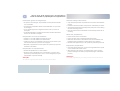
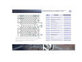
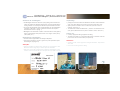
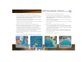
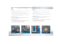
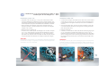
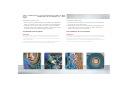
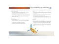
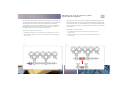
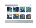
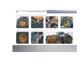
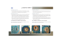
reliability Installation Manual XSXXL Manual de Montagem XS - XXL reliability savings produtividade economia confiabilidade seguarança safety productivity pewag Tire Protection Chains offer optimum protection for the valuable but highly vulnerable EM tires, with the target to ensure that the mines, quarries and other operations keep rolling! The worlds biggest Mining Companies with operations in North- and South America, Europe, Africa, Asia and Australia have chosen the reliability of pewag high quality Tire Protection Chains to increase the productivity of their Earth Moving Equipment. Maximization of tire life and reduction of tire costs as well as maximum equipment availability and low maintenance are the main benefits of pewag Tire Protection Chains. As blindagens protetoras de pneus pewag oferecem excelente proteção aos caros, mas altamente vulneráveis pneus EM, assegurando a continuidade das atividades em minas, pedreiras ou outro tipo de operação. As maiores companhias mineradoras, com operações na América do Sul e do Norte, Europa, África, Ásia e Austrália, escolheram a confiabilidade e a qualidade das blindagens protetoras de pneus Pewag para aumentar a produtividade de seus equipamentos. Principais benefícios das blindagens protetoras de pneus Pewag: aumento da vida útil e conseqüente redução de custos com pneus, baixa manutenção e máxima disponibilidade dos equipamentos. Index Índice 45 6 7 8 9 1011 12 1320 2122 23 24 2526 27 28 2930 31 3233 3437 3842 4346 4749 General risk assessment Work site and equipment preparation Check before installation Mounting tools & spare parts Components of pewag Tire Protection Chains Unpacking lifting out laying out of a Tire Protection Chain Assembly procedure of 2 (4)-part Tire Protection Chains Installation of a Tire Protection Chain (LXXL) Tire Protection Chains with forged tension chain guiding system Correct chain tension Maintenance Adjusting a Tire Protection Chain Re-tensioning Overhauling Removal Re-fitting of used Tire Protection Chains Service Reporting Trouble-shooting Installation of a Tire Protection Chain (XSM) Cone Fit Installation Warnings and instructions for use Installation manual in further languages is available for download under www.pewagtireprotectionchains.com. 45 6 7 8 9 1011 12 1320 2122 23 24 2526 27 28 2930 31 3233 3437 3842 4346 4749 Avaliação geral de riscos Preparações dos equipamentos e local de trabalho Checagens pré-montagem Ferramentas e peças sobressalentes Componentes das blindagens protetoras de pneus pewag Abertura da embalagem - como retirar da embalagem posicionamento da blindagem no solo. Procedimentos de montagem para blindagens fornecidas em 2 ou 4 partes Instalação de uma blindagem protetora de pneus (L - XXL) Blindagem com sistema guia da corrente de tensão Tensão correta da corrente Manutenção Ajustando a Blindagem Retensionamento Reparos Desmontagem Remontagens de blindagem usada Relatórios de serviço Solução de problemas Montagem de uma blindagem protetora de pneus (XS - M) Montagem tipo Cone Fit Avisos e instruções de uso Este Manual de montagem está disponível para download em outros idiomas no endereço abaixo: www.pewgtireprotectionchains.com . General risk assessment Avaliação Geral de riscos 4 Blindagens - Instalação / Desmontagem / Encurtamento / Retensionamento e Reparos Descrição do risco Efeito do risco Pessoal sob risco Ações para minimizar os riscos Gravidade do risco Classificação do risco Ações necessárias para garantir a continuidade do serviço Retirar a blindagem da embalagem (caixa) Danos físicos por esmagamento F/C Utilizar lingas adequadas e firmemente fixadas à blindagem. P A Manter a área de trabalho livre e limpa. Certificar-se de que todas as pessoas envolvidas são habilitadas. Abertura da blindagem no solo Ferimentos na coluna e/ou membros F/C Observe o manual de montagem. Utilize ferramentas adequadas, talhas, ganchos. P A Antes de iniciar a montagem, certifiquese de que a corrente não está torcida ou presa. Elevação da "concha" da carregadeira Falha hidráulica ocasionando sérios ferimentos ou morte F/C Somente pessoas autorizadas devem operar a carregadeira. A "concha" deve permanecer com a abertura voltada para o solo. P A Somente pessoas autorizadas devem operar a carregadeira. Manter-se afastado da "concha". Montagem da blindagem no pneu Esmagamento de mãos e/ou dedos. F/C Somente pessoal treinado deve permanecer próximo à blindagem. Utilizar EPI's adequados. P A Certificar-se de que a blindagem está corretamente posicionada no solo e fixada à corrente de montagem. Desmontagem da blindagem no pneu Esmagamento de mãos e/ou dedos. F/C Somente pessoal treinado deve permanecer próximo à blindagem. Utilizar EPI's adequados. P A Certificar-se de que a blindagem foi solta corretamente. Afastar outras pessoas do local de trabalho. Utilização de maçarico Queimaduras, ferimentos na cabeça e/ou olhos. F/C Somente pessoal treinado, utilizando EPI's apropriados, deve usar o maçarico. Não soldar junto ou mesmo próximo à válvula. P A Afaste outras pessoas e materiais inflamáveis da área. Isole a máquina. Fechamento da blindagem Ferimentos nos dedos F Somente pessoal treinado, utilizando luvas de proteção, está autorizado a realizar o fechamento. P A Verificar se a blindagem está montada corretamente e não serão necessários mais ajustes ou encurtamento. Martelar os pinos dos anéis de fechamento. Ferimentos nos olhos e cabeça F/C Utilizar EPI's adequados. Caso sejam utilizados equipamentos hidráulicos, riscos adicionais devem ser observados. P A Afastar outras pessoas do local de trabalho. Tensionamento da blindagem Esmagamento das mãos. Caso o esticador falhe, podem ocorrer ferimentos na face ou membros. F/C Somente pessoal treinado deve realizar a operação. Verificar previamente as condições do esticador ou talha. P A Certificar-se de que a talha ou esticador esteja corretamente fixado à corrente de tensão. Legenda: Pessoal sob risco: F - Funcionários, C - Funcionários do cliente, Gravidade do risco: P - pequena, M - média, G - grande Risco: A - aceitável, M - requer maior análise, U - inaceitável, Abreviações: EPI - equipamento de proteção pessoal, TPC - blindagem protetora de pneus General risk assessment Avaliação Geral de riscos 5 Tire Protection Chains Installation / Removal / Shortening / Re-tensioning and Repair Hazard Description Hazard effect Description Persons at risk Existing Measures Taken to control risks from the Hazard Effects Resulting Hazard Effect Risk A/M/U Actions Required to allow the job to start/continue Lifting new TPC out of crates using crane / forklift or loader bucket. Chain sling failure leading to injury or death by crushing. E/C Ensure suitable chain sling is used with adequate load capacity. Visually check chain sling for defects and ensure that it is securely connected to TPC. S A Ensure that crane / forklift / machine operator understands the job at hand. Keep well clear of working area. Laying out and moving TPC on ground. Back or limb injury. E/C Observe manual lifting rules. Use apprpriate tools and lifting gear. i.e. crane / forklift etc. S A Assure chain condition, i.e. for twisted or trapped chain, before lifting commences. Raising loader bucket to gain access to inside of tyre and TPC. Hydraulic failure leading to serious injury or death. E/C Only competent persons authorised to operate machine. Once raised, bucket must be supported by turning bucket tip to face the ground. S A Only competent operator allowed inside cab. Keep well clear of loader bucket. Mounting TPC on to tyre. Crushing of hands / fingers. E/C Only competent persons allowed near TPC. Appropriate PPE must be worn. S A Ensure TPC is laid out flat and evenly on ground and connected properly to mounting chain. Removing TPC from tyre. Crushing of hands / limbs. E/C Only competent persons allowed near TPC. Appropriate PPE must be worn. S A Ensure TPC is disconnected properly. Keep other people clear of working area. Cutting sections out of TPC using cayacetylene burning equipment. Burns, head / eye injury. E/C Only competent persons to use cutting equipment. Do not burn on or near tyre / valve. Appripriate PPE must be worn. S A Keep other people and flammable materials clear of working area. Isolate machine. Connecting chain ends together with rings / links. Trapping of fingers. E Only competent persons to make connection. Wearing gloves is practicable. S A Ensure TPC is fitted properly and no alterations / shortening required. Hammering or pressing in retaining pin respectively heavy pins. Eye / head injury. E/C Eye protection and PPE must be worn. When using the hydraulic mounting tool belonging risk assessment are to be observed. S A Keep other people clear of working area. Tensioning TPC. Crushing hands. Injury to face or limbs if lever hoist fails. E Only competent persons to tension TPC. Check condition of lever hoist before use. S A Ensure lever hoist is connected to tension chain correctly. Key: Persons at risk: E = Employees, C = Customer Employees, Hazard effect: S = small, M = medium, L = large Risk: A = Acceptable, M = more analysis required, U = unacceptable, Abbreviations: PSA = personal protective equipment, TPC = Tire Protection Chain 6 Work site and equipment preparation Local de trabalho e preparação do equipamento Instruções gerais de segurança: No processo de montagem, são permitidas somente pessoas treinadas e/ou autorizadas. Os operadores e assistentes devem e star familiarizados com o processo de montagem. O uso de EPI apropriado é obrigatório durante todo o processo de montagem. O manual de instalação e a análise de riscos devem ser lidos atentamente antes de ser iniciada a montagem. Preparação do local de trabalho: Verificar se o local de trabalho está isento de riscos. Verificar se o local de trabalho está desobstruído. Certificar-se de que a carregadeira possa mover-se para frente e para trás livremente durante o processo de montagem. Máquinas e equipamentos somente podem ser operados por pessoas treinadas e autorizadas. Preparação do equipamento: Sinalize adequadamente o local de trabalho. Enquanto estiver trabalhando junto à carregadeira, a "concha" deve permanecer posicionada junto ao solo e o motor desligado (exceções são definidas no presente manual). Atenção: As regras de segurança locais devem ser sempre observadas! General safety instructions: Only authorized personnel are permitted to be involved in the installation process. Familiarize involved assistants and operators of installation procedure. Appropriate Personal Protective Equipment (PPE) must be worn during the entire mounting process. Read risk assessment and installation manual carefully before start of mounting. Work site preparation: Ensure that work area is hazard free. Inspect the work area for height and width obstructions. Make sure that machine to be chained can be moved forwards and backwards during installation procedure without any obstacles. Machines and equipment only to be operated by authorized personnel. Equipment preparation: Place appropriate safety tags or locks at the regulated isolation points on the machine before start of work. While working at the machine / tire loader bucket must be in down position and engine shut down (except defined stages of installation process). Attention: Local safety regulations of your country must be observed at all times! Check before installation Verificação prévia Verificar antes da instalação: A dimensão do pneu (L2 -L5) e da blindagem. A pressão do pneu (Nota: utilizar a pressão recomendada pelo fabricante). Condições gerais do pneu (cortes, defeitos ou qualquer outra condição de risco) A distância entre os pneus e outros componentes da máquina vejao quadro: "Distâncias recomendadas para TPC (blindagens)". Alternativas para montagem com espaçamento reduzido: Alterações no veículo (remover ou mudar a posição dos paralamas) Utilizar pneus menores ou semi novos Alterações ou troca das blindagens 7 Check before installation: Check tire dimension, tire tread (L2L5) and match with chain size. Air pressure in tire (Note: use the recommended air pressure of tire manufacturer!). Inspect tires for dangerous damage. Check distances between tire and machine components see chart: "Recommended clearances for TPC". Remedy for limited clearance: Alteration to the vehicle (e.g. rim offset, remove mudguard or change position etc.). Use of smaller or part worn but still useable tires. Alteration or exchange of Tire Protection Chains. Recommended clearances for TPC: Distâncias recomendadas para TPC (blindagens): "M" (mm) "F*" (mm) "R" (mm) Ringstar * F measured at lowered shovel "F" medida realizada com a concha baixada ** "D measured horizontally "D" medida horizontal Achtung: F & M bei Pendelachse auf Anschlag messen Atenção: "F" & "M" compreendem a oscilação total do eixo. 12 70 - 50 70 14 80 - 60 80 16 90 115 70 90 18 100 - 70 100 21 120 - 80 110 23 120 - 80 110 * measured at lowered shovel medida realizada com a concha baixada 8 Mounting tools & spare parts Ferramentas de montagem & peças sobressalentes Ferramentas de montagem: Nº. 49 - talha Nº. 50 - esticador Nº. 51 - saca-pino para anéis de fechamento ou reparo, ver nº. 31. Nº. 52 - saca-pino para links de reparo, ver nº. 37 / 39. Nº. 53 - esticador hidráulico Nº. 54 - ferramenta para fechamento de anel Nº. 58 - gancho de montagem Nº. 59 - alavanca de montagem Mounting tools: part no. 49 - Lever hoist part no. 50 - Assembly pliers part no. 51 - Pin Driver (for connecting-/ repair ring no. 31) part no. 52 - Pin Driver (for pin lock no. 37/38 and VBS) part no. 53 - Hydraulic tool set part no. 54 - Mounting tool for connecting-/ repair ring part no. 58 - Drawing-out hook part no. 59 - Mounting spike As ferramentas mostradas no quadro abaixo são as recomendadas para montagem de TPC (blindagens) Tools marked in bold print are recommended for the installation of Tire Protection Chains (minimum requirement). peças de reparo: Nº. 24 - manilha Nº. 31 - anel de fechamento / reparo Nº. 37 - link de reparo Nº. 39 - link de fechamento VBS Spare Parts: part-no. 24 - End shackle part-no. 31 - Connecting-/ repair ring part-no. 37 - Pin lock part-no. 39 - VBS, connecting lock 49 50 51 52 24 31 53 54 58 59 37 39 Components of Tire Protection Cahins Componentes da blindagem (TPC) 3 No. Nº. 5 1 9 2 3 12 10 8 13 6 7 4 5 6 7 8 9 2 1 4 11 10 11 Notice: The components of a Tire Protection Chain as well as the exact construction are dependent on the type of machine and tire. For questions please contact your local pewag partner. Aviso: Os componemtes e a exata construção das blindagens dependem do tipo de máquina e do pneu. Para maiores informações, por favor contate o representatnte Pewag local. 12 13 Description Descrição Tread chain ring Anel da banda de rodagem Tread chain link Link da banda de rodagem Inner chain Corrente interna Side chain link Link da banda lateral Tension chain Corrente de tensão Connecting-/ repair ring Anel de fechamento / reparo Pin lock Anel de reparo Pin lock for inner chain Link para corrente interna VBS Connecting lock Link de fechamento VBS Locking plate Placa de fechamento Tension chain ring Anel da corrente de tensão End shackle Manilha Tension chain connector Conector da corrente de tensão 9 Repair with part no. Reparo com a peça nº. 31 37 37 37 26 31 37 37 39 28 31 +48 24 31 + 56 10 Unpacking lif ting out laying out Abertura - retirar da embalagem - posicionamento no solo Abertura da embalagem: As Blindagens Protetoras de Pneus (TPC) pewag são fornecidas em caixas de madeira de diferentes dimensões. Os dados da blindagem estão gravados em uma etiqueta afixada na parte dianteira da caixa. As peças sobressalentes estão acondicionadas em uma embalagem colorida e codificada (o código é também informado na etiqueta identificadora externa - veja fig. 1) Blindagens com dimensões ? 50/65-51 são fornecidas em duas (quatro) partes (a identificação das partes é feita como segue: 1/Start (início); 1/End (final); etc.). Retirada da embalagem: Somente utilize equipamento de elevação adequado. Para iniciar a elevação, encaixe o gancho no ponto pintado de preto da blindagem (veja figura 2). Atenção: Risco de acidente na abertura das cintas de aço que fecham a caixa. Mantenha área de segurança e demais pessoas afastadas. Não use a corrente de montagem para a elevação da blindagem. Utilize somente correntes específicas para a elevação de cargas (G80 ou G100). Unpacking: pewag Tire Protection Chains are delivered in wooden crates of different sizes. The chain details can be found on the front side of the crate. Spare parts are located in colour coded crate (see also notice on marking, see picture 1). _ 50/65-51 are delivered in two Tire Protection Chains with Dimension > (four) parts (identification of the parts as follows: 1/Start; 1/End; etc.). Lifting out: Use only appropriate lifting equipment for lifting. To allow a smooth lift out, connect the lifting hook to the black coloured point on the Tire Protection Chain (see picture 2). Attention: Opening of crate - risk of injury when cutting the steel belts - keep hazard area clear. Do not use mounting chain for lifting. Unpacking lif ting out laying out 11 Abertura - retirar da embalagem - posicionamento no solo Posicionamento da blindagem no solo: Coloque a blindagem (com a corrente de tensão galvanizada e as partes: 1/Start; 2/Start; etc.) no piso da área de trabalho com a superfície de desgaste dos links voltada para o solo e a corrente de tensão no lado externo em relação ao pneu da máquina. Estenda a malha de corrente, formando uma única esteira retangular; a corrente interna deve formar uma linha reta. Certifique-se de que todos os links estejam posicionados corretamente (nenhum link pode ficar na posição vertical). Laying out of a Tire Protection Chain: Lay the Tire Protection Chain (first half with the zinc plated tension chain, marked as Chain: 1/Start or 2/Start etc.) on the work area floor with the heavier wear surface of the link face downwards and the tension chain to the outside. Stretch the chain mesh sidewards wards out into a neat rectangular mat; inner chain in a straight line. Take care that all links are lying flat and orderly (no links to be standing up vertically). Continue para blindagens formadas por duas ou quatro partes: Posicione a segunda metade (identificada como: 1/End; 2/End; etc.) adjacente à primeira metade. Verifique se a corrente de tensão e os seus respectivos anéis estão alinhados com a primeira parte da blindagem e voltados para o lado externo em relação ao pneu onde será montada; novamente confira se os links estão com a superfície de desgaste voltada para o solo e na posição horizontal. Estenda novamente a blindagem e una a duas metades através dos pontos de conexão. continue for chains consisting out of two (four) halves: Lay the second half (marked as Chain: 1/End or 2/End etc.) out, adjacent to the first half. Make sure that tension chain side (oval tension rings) correspond with first half and look to the outside; again with the heavier wear surface of the link face down. Stretch out the chain once more in a neat parallel configuration with the two halves to be joined, butting up together at the connecting points across the chain mesh. Continue com o procedimento para blindagens fornecidas em quatro partes. Continue procedure for 4-part chains. 12 Assembly procedure of 2-(4) part TPC Procedimento de montagem para TPC de 2-(4) partes a. Inicie a montagem no lado interno da blindagem. b. Conecte a corrente interna, utilizando o link da banda lateral (peça nº. 37) (link de fechamento VBS, peça nº. 39 para blindagens de 21 e 23 mm). c. Conecte os links duplos e os links de desgaste com os anéis de fechamento (Peça nº. 31). Use um martelo e a ferramenta específica de fechamento (peça nº. 54) ou ferramenta hidráulica de montagem para inserir o pino no local de travamento da peça. d. A tampa do anel de reparo deve ficar voltada para a lateral da blindagem... e. ... formando um ângulo de 90º em relação à banda de rodagem. f. Finalmente passe a corrente de tensão através dos anéis, certificando-se de que todos os anéis de passagem ovais estão incluídos. g. Repita o processo na segunda parte da blindagem. h. Verifique se todas as partes da blindagem estão perfeitamente alinhadas e os links e anéis corretamente posicionados. a. Start the assembly from inside to the outside of the chain. b. Connect the inner chain with pin lock (part no. 37) (VBS connecting lock, part no. 39 at 21 and 23 mm chains). c. Connect duplex (double) links and drop forged wear links with the connecting rings (part no. 31). Use a hammer and mounting tool (part no. 54) or hydraulic mounting tool to drive heavy pin into the locking piece. d. Locking piece of the connecting ring should be positioned so that the block is in circumferential direction at the side parts of the chain ... e. ... and 90° to the circumferential direction at the tread area (see picture 3). f. Finally connect the outside chain together with the connecting ring, ensuring that the large oval tension ring is included in the assembly at this point. g. Thread the tension chain trough the oval tension rings on the second half of the chain. h. Ensure both halves are positioned straight and parallel with all links laying flat and orderly. A montagem está completa e a blindagem pronta para ser instalada no pneu! Continue com o procedimento para blindagens fornecidas em quatro partes. Assembly completed and ready for installation! Continue assembly for 4-part chains. e b d Hydraulic-Werkzeug hydraulic mounting tool f Installation of a Tire Protection Chain LXXL Instalação de blindagens L - XXL 13 Atenção: recomendamos seguir os procedimentos abaixo antes de iniciar a montagem, tornando-a, assim, mais fácil e rápida: Após estender a blindagem no solo, formando uma esteira retangular, verifique se a corrente de tensão está passando através de todos os anéis ovais. O elo marcado (colorido) da corrente de tensão deve combinar com o último anel oval da blindagem. Amarre a corrente de tensão ao último anel de apoio externo (anel ao qual o anel oval está conectado) utilizando aproximadamente 50 cm de corda com 9 ou 10 mm de diâmetro (utilize somente cordas especiais para movimentação de cargas). Repita este processo intercalando um anel de apoio amarrado e um solto, certificando-se de que o primeiro e o último anel estejam amarrados. Notice: For an easier and faster installation of Tire Protection Chains we recommend to prepare the chains in the following way before start of actual installation: After chain is laid out in a neat rectangular mat ensure that the tension chain is pulled taut through the tension chain rings. The colour marked link of the tension chain should match with the last oval tension ring of the entire chain. Tie the tension chain to the last rings of the outer bracing (where oval tension rings are connected to) with a half metre length of 9 to 10mm rope (make sure that using a high load rated rope). Repeat this process on every second ring, ensuring both first and last rings are secured to the tension chain. O objetivo do procedimento acima mencionado é manter a blindagem na forma retangular, paralela e centralizada durante sua instalação no pneu. The object of above mentioned exercise is to hold the mesh in a square and parallel configuration during the installation of the chain onto the tire and to prevent the chain mesh from running off centre during the chain installation. LXXL 14 Installation of a Tire Protection Chain LXXL Instalação de blindagens L - XXL Atenção: Durante todo o processo de instalação, a comunicação com o operador da carregadeira deve ser constante! Antes da carregadeira ser movimentada, certifique-se de que a área ao redor está livre e todas as precauções foram tomadas! Quando estiver trabalhando próximo ao pneu, tenha certeza de que a "concha" da carregadeira está travada e o motor da máquina desligado (exceções são definidas no presente manual). Instalação passo 1: Conduzir a carregadeira sobre a blindagem, parando a cerca de 30 - 60 cm da sua extremidade. Instalação passo 2: Coloque a corrente de montagem em torno do pneu como mostrado na foto e verifique se está bem presa em algum gomo. Feche a alavanca posicionada ao lado do pneu. Attention: Keep communication to the loader driver always online during the whole installation process! Ensure the area behind the loader is clear and all precautions are in place when moving the loader! When working close to the tire make sure that the bucket of the loader is secured and engine shut down (except defined stages of mounting). Installation Step 1: Drive the loader tire along the centre of the chain mat and stop at a distance of approx. 30-60 cm (1-2 ft) from the end. Installation Step 2: Put the mouting chain over the tire as shown in the picture and ensure that a good grip in the tire lugs is achieved. Close the lever in a position at the side of the tire. Installation of a Tire Protection Chain LXXL Instalação de blindagens L - XXL Instalação passo 3: Fixe a extremidade final da blindagem à corrente de montagem, utilizando os ganchos "S" encontrados em 3 ou mais pontos como mostrado na foto. 15 Installation Step 3: Attach the end of the Tire Protection Chain to the mounting chain using the S-hooks provided at three or more points as shown in the picture. 16 Installation of a Tire Protection Chain LXXL Instalação de blindagens L - XXL Instalação passo 4: Movimente o veículo lentamente em marcha ré. A blindagem começará a cobrir o pneu. Pare a carregadeira a intervalos regulares, baixe e trave a "concha" para garantir a segurança das pessoas que estão trabalhando próximas do pneu. Use a alavanca de montagem para ajustar e centralizar a blindagem no pneu. Este procedimento deve ser realizado com cuidado, pois as seções da blindagem podem repentinamente deslocar-se para a posição correta. Continue movimentando o veículo em marcha ré até as duas extremidades da blindagem encontraram-se em posição adequada para o fechamento final. (A posição correta do "encontro" das extremidades da blindagem é entre 7-8 horas no lado esquerdo da carregadeira , e entre 4-5 horas no lado direito - veja foto abaixo). Installation Step 4: Drive the loader slowly backwards. This will begin to pull the chain mesh over the tire. Stop loader at regular intervals, lower and support the bucket to ensure safety of the personnel working close to the tire. Use mounting spike or lever bar to adjust the chain across the face and to keep it centred. Caution must be taken when relieving any bunching, as sections of the mesh may drop suddenly into correct position. Continue to reverse the loader in stages until both ends of the chain come together at a convenient height to proceed with final connection (The correct position of the chain join is between 7- 8 o'clock on left hand side of machine and 4-5 o'clock on the right hand side). Installation of a Tire Protection Chain LXXL Instalação de blindagens L - XXL Instalação passo 5.1: Corte e remova todas as cordas e passe a corrente de tensão através dos anéis até a placa de fechamento, aliviando qualquer tensão da corrente. Conecte a corrente interna com o link de fechamento (pç. nº. 37 / VBS, pç. nº. 39 para blindagens de 21 e 23 mm). Use uma talha e as ferramentas de montagem para manter as duas partes unidas enquanto as peças de fechamento são instaladas e travadas. Conecte e trave na corrente interna, com o anel de reparo (pç. nº. 31), todos os links marcados de vermelho. Utilize um martelo e o saca-pino (pç. nº. 54) ou uma ferramenta hidráulica de montagem (pç. nº. 53) para introduzir o pino elástico na tampa do anel. 17 Installation Step 5.1: Remove/cut all ropes and thread the tension chain back through the rings toward the locking plate, relieving any tension on the chain. Connect the two ends of the inner chain at the colour marked points with pin lock (part no. 37 / VBS connecting lock, part no. 39 at 21 and 23mm chains). Use lever hoist and assembly pliers to draw the two ends together until the pin lock can be installed and secured. Connect and secure all links marked red on the inner chain side with connecting ring (part no. 31). Use hammer together with mounting tool (part no. 54) or hydraulic mounting tool (part no. 53) to drive the heavy pin into the locking piece. Locking piece of the connecting ring should be positioned so that the block is in the vertical plane. 18 Installation of a Tire Protection Chain LXXL Instalação de blindagens L - XXL Instalação passo 5.2: Utilizando o link de reparo (pç. nº. 37), junte os dois anéis do lado externo da blindagem, exatamente no ponto marcado (pintado). Use uma talha e as ferramentas de montagem para manter as duas partes unidas enquanto as peças de fechamento são instaladas e travadas. Abra a corrente de montagem. Utilize chave de fenda robusta ou alavanca para abrir o anel de fechamento da corrente de montagem. Atenção com as mãos. Remova todos os ganchos "S". Continue a unir as duas partes da blindagem com os anéis de reparo (pç. nº. 31). Utilize martelo e a ferramenta para fechamento de anel (pç. nº. 54) ou a ferramenta hidráulica (pç. nº. 53), para introduzir o pino elástico na tampa do anel. As tampas dos anéis de reparo devem ser posicionadas horizontalmente em relação à banda de rodagem. Atenção: Na introdução do pino elástico é recomendada a utilização da ferramenta hidráulica de montagem. A segurança e a eficiência da montagem serão otimizadas e seus riscos reduzidos. Installation Step 5.2: Connect the two rings at the outside of the chain at the colour marked points with pin lock (part no. 37). Use lever hoist and assembly pliers to draw the two ends together until the pin lock can be installed and secured. Open the mounting chain. The use of a large screwdriver or lever bar is recommended to release the lock ring on the mounting chain lever plate. Keep hands clear! Remove all S-hooks. Continue to connect the two chain ends with the connecting rings (part no. 31). Use hammer together with mounting tool ( part no. 54) or hydraulic mounting tool (part no. 53) to drive heavy pin into the locking piece. Locking pieces of the connecting rings should be positioned in the vertical plane at the side parts of the chain and horizontally at the tread area. Attention: For driving in the heavy pin of the connecting ring, the use of the special hydraulic mounting tool is highly recommended. Safety and efficiency of the assembly will be increased and the danger of steel splinters causing injury minimized! Installation of a Tire Protection Chain LXXL Instalação de blindagens L - XXL Instalação passo 6.1: Prenda a talha no final da corrente de tensão e na lateral da blindagem, conforme mostrado na foto 1. Inicie o tensionamento da corrente, certificando-se de que ela está passando através de todos os anéis ovais de tensão. Alinhe os anéis de tensão com um martelo. Este procedimento irá garantir o livre movimento da corrente de tensão através dos anéis. Trave a placa de fechamento na corrente de tensão e remova a talha. Movimente a carregadeira para a posição mostrada na foto nº 4 e retire a corrente de montagem. Em linha reta, dirija a carregadeira para frente e para trás, até que a blindagem esteja corretamente centralizada e pare na posição inicial. Utilizando a talha, estique novamente a corrente, como descrito anteriormente. Trave a placa de fechamento na corrente de tensão novamente e remova a talha. 19 Installation Step 6.1: Attach the lever hoist to the end of the tension chain and to the chain sidewall as shown in picture 1. Start to tighten the chain, drawing the tension chain through the oval tension chain rings. Align the tension chain rings with a hammer against the direction of pull. This will assist the tension chain to move freely through the tension chain rings. Secure the locking plate back into the tension chain, relieve and remove lever hoist. Move loader in the position shown in picture 4 and remove the fitting chain. Drive the machine forward and backward in a straight line until the chain is correctly centred and stop in original position. Re-attach lever hoist and repeat tightening process as described before. Secure the locking plate again back into the tension chain, relieve and remove lever hoist. 20 Installation of a Tire Protection Chain LXXL Instalação de blindagens L - XXL Instalação passo 6.2: Repita o processo quantas vezes forem necessárias até que a blindagem esteja com a tensão correta. (veja p. 23: tensão correta da blindagem). Finalmente retire a talha e estique o excesso da corrente de tensão através dos anéis ovais. Prenda com a manilha o último elo da corrente de tensão ao anel da lateral da blindagem mais próximo. Installation Step 6.2: Repeat whole process a number of times until chain is correctly tensioned. (see page 23: correct chain tension). Finally remove lever hoist and taut the tension chain tail through the oval tension chain rings. Attach the last link of the tension chain with the shackle to the closest ring of the sidewall. A instalação está completa. The installation is now complete. Atenção: Para evitar a quebra de links e anéis por excesso de tensão, a pewag desenvolveu um indicador de tensão que se romperá em caso de supertensionamento. Outros links da corrente de tensão serão soltos e a mesma afrouxará. Todas as blindagens para pneus > 45/65-45 possuem este indicador de sobrecarga (favor verificar as condições de garantia pewag) Attention: To avoid link or ring breakages due to over tensioning pewag developed an overload indicator which will break in case of over tensioning. Additional links in the tension chain will be released and the chain loosened. _ 45/65-45 are standard equipped with this overload All chains from tire size > indicator (Please see pewag warranty conditions!). TPC with forged tension chain guiding system 21 Blindagem com sistema-guia da corrente de tensão Na instalação de blindagem com sistema-guia, algumas pequenas alterações no procedimento são necessárias. Considere com especial atenção os passos abaixo: Na montagem e na instalação da blindagem, passe a corrente de tensão através do olhal superior (A) do sistema-guia. Caso necessário alinhe o sistema-guia com um martelo. Após o correto tensionamento da corrente, passe o excesso da corrente de tensão através do olhal inferior (B) do sistema-guia. Prenda com a manilha o último elo da corrente de tensão ao anel da lateral da blindagem mais próximo. Benefícios: As blindagens pewag, equipadas com o sistema-guia, oferecem as seguintes vantagens: Durante o tensionamento, a corrente de tensão desliza facilmente através dos olhais do sistema-guia, facilitando todo o processo. Enquanto a blindagem é apertada, o sistema-guia a mantém centralizada, e o alinhamento de suas partes não é necessário. O terminal da corrente de tensão é facilmente fixado. For chains with forged tension chain guiding system minor changes in the installation process do apply. Please pay attention to following points in special: At the assembly as well as at the installation respectively at the tightening draw the tension chain through the upper hole (A) of the tension chain guiding system. If necessary align the tension chain guiding system with a hammer against the direction of pull during tensioning. After chain is correctly tensioned taut the end of the tension chain through the bottom hole (B) of the tension chain guiding system. Attach the last link of the tension chain with the shackle to the closest ring of the sidewall. Benefits: pewag Tire Protection Chains equipped with the forged tension chain guiding system offer the following advantages: While tensioning the tension chain glides smoothly through the openings of the tension chain guiding system and therefore the whole tension process gets easier. During the tightening the tension chain guiding system keeps itself centred and the alignment of the parts with a hammer widely does not apply. Simple storage of tension chain endings. A B 22 TPC with forged tension chain guiding system Blindagem com sistema-guia da corrente de tensão Observação quanto ao encurtamento: nas blindagens equipadas com sistema-guia da corrente de tensão, os "links" de passo longo da lateral externa e a própria guia forjada formam uma única unidade. Em caso de encurtamento, preste atenção para não romper esta unidade, a fim de realizar futuras alterações. O anel localizado junto ao "link" de passo longo é que deve ser cortado, e os "links" de passo longo unidos através de anel de reparo. Observação quanto à manutenção: em caso de quebra do sistema-guia, a unidade completa ( peça forjada + os dois "links" de passo longo) deve ser substituída. A montagem pode ser realizada com a utilização de dois anéis de reparo. Notice for shortening: At chains equipped with the tension chain guiding system the long pitch links of the outer side chain together with the forged component form a unit. When shortening the chain pay attention not to destroy this unit in order to allow later elongation. Therefore instead of the long pitch link the neighbouring welded ring is to be cut and to be re-placed by a repair ring (see the cut deviation in picture 3). Notice for maintenance: In case of breakage of the tension chain guiding system the entire unit (forged component incl. long pitch links) needs to be replaced. Mounting to be done by the use of two repair rings. Correct chain tension Tensão correta da blindagem 23 A corrente de tensão pode ser esticada manualmente pela lateral do pneu. Uma pequena "bolsa" (folga) deve ser formada no centro da blindagem, na base do pneu. A dimensão da bolsa varia entre 5 e 10% da largura do pneu. The tension chain can still be pulled away from the tire sidewall by hand. A small bag at the centre of the tread, at the base of the tire has to be seen. The size of the bag should vary between min 5% and max 10% of the tire width. Exemplo: "Pneu 45/65-45, largura 45" x 25,4 mm = 1143 mm x 5% = 57 mm e x 10% = 114 mm, medidas entre o link no centro da banda central e a superfície do pneu. Example: tire 45/65-45, width 45 inch x 25,4 = 1143 mm x 5 % = 57 resp. x 10 % = 114 mm to be measured between link bottom in the centre and tire surface. Atenção: Blindagens em pneus novos. De acordo com nossa experiência, sabemos que pneus novos apresentam aumento entre 3 e 5% no seu diâmetro durante o primeiro mês de operação (um pneu 53,5/85-57 aumenta mais de 18 cm no diâmetro e 56 cm na circunferência). Para evitar a quebra de links e anéis por excesso de tensão, a blindagem deve ser instalada com certa folga e a tensão ser checada regularmente. Attention: Tire Protection Chains on new tires From our experience we know that new tires grow in diameter up to 35% within the first month of operation (e.g. a 53.5/85-57 tire increases up to 18 cm in diameter and 56 cm in circumference). To avoid link or ring breakages due to over tensioning the chain must be fitted loosely on new tires and tension must be checked regularly. 5% 10% 24 Maintenance Manutenção Verifique regularmente o posicionamento e a tensão da blindagem. Após certo período de operação a blindagem começará a afrouxar devido ao desgaste interno dos anéis e links. Torna-se necessário tensionar novamente a blindagem (veja p. 27). Antes do final da vida útil da blindagem, poderá ser necessário encurtá-la, retirando uma ou mais malhas (veja p. 26). Inspecione regularmente a blindagem à procura de elementos avariados. Caso alguma quebra seja verificada, o conserto deve ser imediatamente realizado, utilizando as peças de reparo Pewag apropriadas (veja p. 28). Check correct chain fit and tension regularly. After a certain period of operation the chain becomes loose due to inner wear of links and rings. Re-tensioning of the chain will become necessary (see page 27). In the last third of chain lifetime it might be necessary to shorten the chain by cutting off one or more sections of the chain net (see page 26). Inspect the chain mesh for any breakages regularly. If breakages have occurred to any components, these repairs must be done immediately with the appropriate pewag spare parts (see page 28). A pewag recomenda que sejam realizadas inspeções visuais a cada mudança de turno (troca de operador). pewag recommends that a short visual inspection is carried out before every shift (operator change). Adjusting a Tire Protection Chain Ajuste da blindagem As dimensões das blindagens pewag correspondem às dimensões dos pneus padrão. Alguns ajustes podem ser necessários no caso da instalação de blindagens em pneus com dimensões diferentes dos padrões estabelecidos. Para pequenas adaptações (por exemplo, centralizar a blindagem), ajustar a corrente interna é suficiente, caso contrário, a blindagem inteira deverá ser encurtada ou alongada. Ajuste da corrente interna: Alongamento (figura a): com extensão e anel de reparo (pç. Nº. 37). Encurtamento (figura b): remover 3 links, fechar com link de reparo (pç. Nº. 37) a. 25 pewag Tire Protection Chain sizes correspond to standard dimension tires. When installing TPCs on tires with non-standard dimensions adjustments may have to be made. For fine adaptations (e.g. centering of chain) altering of inner chain will be sufficient, otherwise whole chain has to be shortened or lengthened. Altering of inner chain: Lengthening (picture a): with extension piece and pin lock (part no. 37). Shortening (picture b): remove three links, fasten with pin lock (part no. 37). b. Adjusting a Tire Protection Chain Ajuste da blindagem 26 Grandes adaptações na blindagem: Para grandes alterações nas blindagens, recomendamos que a mesma seja desinstalada (ver p. 29-30). Estenda a blindagem no solo e inicie o processo de ajuste. Alongamento: Fixe a cinta de extensão X com os anéis e links de reparo (pçs. 31 e 37/39), como mostrado na figura a. Encurtamento: Utilizando um maçarico, remova a cinta de encurtamento Y, cortando os anéis e links como mostrado na figura b. Antes de iniciar o procedimento, marque as partes que deverão ser cortadas. Atenção: Quando estiver utilizando o maçarico, não aqueça os anéis e links adjacentes, pois pode ocorrer perda de dureza nestes elementos. Aviso: Para identificar os pontos de fechamento e facilitar a instalação, os finais das novas blindagens estão marcados com fitas coloridas. A mesma marca é encontrada em uma cinta (2 malhas) antes do final da blindagem, caso a mesma precise ser encurtada. a. Altering the whole chain, if altering of the inner chain is insufficient: We recommend to dismantle the chain (see page 2930) for alteration of the whole chain! After that lay the chain out again as described in the installation manual and start the alteration process. Lengthening: fix extension piece X with connecting-/ repair rings (part no. 31) pin lock (part no. 37) and/or VBS connecting lock (part no. 39) as shown in picture a. Shortening: remove the shortening piece Y by torch cutting the welded rings and links at the shown points in picture b. Before start of procedure mark parts which have to be cut off with colour spray. Attention: Do not heat the neighbouring rings or links during torch cutting as loss of hardness is possible! Notice: The ends of new Tire Protection Chains are marked with coloured tapes to display the closing points during the fitting process. The same markings can be also found one section (2 fields) behind the very end in case the chains have to be shortened at the initial installation. b. 37 31 37/39 x y Re-tensioning Re-tensionamento O pneu deve ser movimentado de forma que a placa de fechamento fique em posição de 16 h. Abra a manilha da corrente de tensão e retire a ponta final da mesma do anel oval. Instale a talha na corrente de tensão (próximo da placa de fechamento) e na lateral da blindagem; somente após abra a placa de fechamento. Comece a esticar a corrente. Alinhe os anéis de tensão com um martelo. Este procedimento facilitará a passagem da corrente através dos anéis. Trave a corrente de tensão na placa de fechamento e remova a talha. Em linha reta, movimente a máquina para frente e para trás até que a blindagem esteja corretamente centrada. Volte à posição original. Caso a tensão ainda não seja suficiente, instale novamente a talha e repita novamente todo o processo. Repita todo o processo até a blindagem estar corretamente tensionada. Retire a talha, passe o excesso da corrente de tensão através do olhal inferior (B) do sistema-guia. Prenda com a manilha o último elo da corrente de tensão ao anel da lateral da blindagem mais próximo. Aviso: a freqüência do re-tensionamento depende do desgaste da blindagem. O desgaste é influenciado por diversos fatores, como, por exemplo, a abrasividade da rocha, distâncias percorridas, presença de água, inclinações, velocidade e maneiras de pilotar o equipamento. 27 The tire should be positioned in such a way that the locking piece (locking plate) / connecting row is at about 4 o'clock position. Open shackle at the last link of the tension chain and pull the loose end of the tension chain out of the oval tension chain rings. Attach the lever hoist to the tension chain (near the locking plate) and to the chain sidewall so that the locking plate can be opened. Start to tighten the chain and open locking plate. Align the tension chain rings with a hammer against the direction of pull. This will assist the tension chain to move freely through the tension chain rings. Secure the locking plate back into the tension chain, relieve and remove lever hoist. Drive the machine forward and backwards in a straight line until the chain is correctly centred and stop in original position. If tension is still too loose, re-attach lever hoist and repeat tightening process. Repeat whole process a number of times until chain is correctly tensioned. (see page 23). Finally remove lever hoist and taut the tension chain tail through the oval tension chain rings. Attach the last link of the tension chain with the shackle to the closest ring of the sidewall. Notice: The frequency of re-tensioning depends on the wear rate of the chain. The wear rate, in turn, is influenced by the abrasiveness of the rock, driving distances, moisture, inclines, speed and manner of driving, etc. Overhauling Reparos 28 Para evitar o agravamento do dano, sempre consertar imediatamente a blindagem, utilizando as peças de reparo Pewag. As peças de reparo originais Pewag garantem total recuperação da blindagem, mantendo sua vida útil e proteção aos pneus. Substituição de anel (figura a), utilizando anel de reparo (pç. nº 31). Substituição de link (figura b), utilizando link de reparo (pç.nº. 37). Repair the chain immediately with pewag spare parts in order to avoid further damage to the chain. Original pewag spare parts fully replace damaged chain parts thus maintaining chain life as well as tire protection. Replacement of a horizontal ring (diagram a) with connecting-/repair ring (part no. 31). Replacement of vertical links (diagram b) by pin lock (part no. 37). 2 2 1 a. 1 b. Removal Desmontagem A área de trabalho deve estar limpa e possuir comprimento > que 15 m. O pneu deve ser movimentado de forma que a placa de fechamento fique em posição de 16 h na roda dianteira direita, e na posição 08 h na roda dianteira esquerda. Abra a manilha da corrente de tensão e retire a ponta final da mesma do anel oval. Instale a talha na corrente de tensão (próximo da placa de fechamento) e na lateral da blindagem; somente após abra a placa de fechamento. Abra a placa de fechamento. Após liberar a placa de fechamento, afrouxe a corrente de tensão até formar uma grande bolsa na parte inferior frontal do pneu. Solte o link de reparo interno (links VBS para correntes de 21 e 23 mm) e externo (utilize um saca-pinos ou a ferramenta hidráulica de montagem) e separe-os da blindagem. Abra todos os anéis de fechamento (utilize um saca-pinos ou a ferramenta hidráulica de montagem) e os retire da blindagem. Nota: Pode ser utilizado um maçarico na abertura dos anéis de fechamento. Tenha o cuidado de não aproximar a chama do pneu e não corte nenhum anel forjado da malha da blindagem. Remova as peças cortadas para um local seguro. 29 Chose a large working area free of hazards, with a length > 15 m. The tire should be positioned in such a way that the locking piece (locking plate) / connecting row is at about 4 o'clock position on the right hand front wheel respectively at 8 o'clock position on the left hand front wheel. Open shackle at the last link of the tension chain and pull the loose end of the tension chain out of the oval tension chain rings. Attach the lever hoist to the tension chain and to the chain sidewall so that the locking plate can be opened. Start to tighten the chain until locking plate can be opened. After locking plate is released loosen tension chain until a substantial bag is achieved at the bottom front of the tire. Open the pin locks on the inside (VBS connecting lock at 21 and 23mm chains) and outside (drive in the pin from below with pin driver part no. 52 or hydraulic mounting tool) and detach from chain by the help of a lever hoist or assembly pliers. Open connecting rings (drive out the heavy pin with pin driver part no. 51 or hydraulic mounting tool) and remove each connecting ring across the face of the chain. Notice: Instead of using pin drivers or hydraulic tool for opening the joining components a cutting torch can also be used. Take care to keep flame away from tire and do not cut any forged links across the chain mesh. Remove all hot off-cuts to a safe position! 30 Removal Desmontagem Atenção: Assegure-se de que a talha suportará o peso da blindagem quando os anéis de fechamento forem abertos ou cortados; ou a blindagem poderá soltar-se repentinamente. Quando terminar o processo, remova da área todas as peças e ferramentas. Observando todos os procedimentos de segurança, movimentar lentamente a máquina em marcha ré enquanto a blindagem é gradualmente removida do pneu. Cuidados redobrados devem ser tomados quando a parte final da blindagem escorregar pela parte traseira da roda; todo o pessoal deve manter-se afastado da máquina nesta parte do procedimento. Para outras blindagens, repita o mesmo processo. Attention: Ensure that the bottom section of the chain mesh is supported by a lever hoist to prevent the mesh dropping suddenly when connecting rings are removed or cut! When process is finished remove all parts and tools from working area. When safe to do so, slowly reverse machine backwards directing the operator as the chain is gradually removed from tire. Caution must be taken when final section of chain drops from tire tread behind the wheel; all personnel must be clear of the machine at this point of the exercise. Repeat process for other chains if required. Re-fitting of used Tire Protection Chains Reinstalação de blindagens usadas Para identificar corretamente os pontos de conexão durante o processo de instalação, siga os procedimentos abaixo: Estenda a blindagem conforme informado na p. 11. Identifique e marque os últimos links da lateral interna (posição 1). Marque o anel localizado na lateral externa da blindagem, ao qual está fixada a placa de fechamento (posição 2). Na outra seção da blindagem, marque o último anel da lateral externa (posição 3). Identifique e marque nas duas seções da banda central da blindagem os primeiros links de conexão (posição 4). Continue com a instalação conforme páginas13-20. 31 To identify the correct connection points during the installation process, the following procedure is recommended: Lay the chain out in the proper configuration (see page 11). Identify and mark the last links on both ends of the inner chain with coloured tape (position 1). Mark the ring which is attached to the locking plate on the outside chain (position 2). On the opposite end mark the last ring of the outer side chain with matching tape (position 3). Identify and mark the first connection links on both of the sides of both ends of the main chain mesh (position 4). Continue with installation procedure (see page 1320)! 1 2 4 4 3 32 Ser vice Reporting Relatórios de Ser viço A pewag recomenda a utilização de relatórios padronizados no acompanhamento da vida da blindagem (estes documentos são obrigatórios, caso a Pewag, voluntariamente, garanta um determinado período de vida útil para a blindagem). Dados que devem constar no relatório: Marca e modelo da máquina e seu respectivo código na frota (Ex.: CAT 994 nº. 3). Dimensões dos pneus (Ex.: 55/80-R57). Horímetro atualizado. Horímetro na instalação das blindagens. Data de montagem das blindagens. Horas de serviço das blindagens. Modelo da blindagem (Ex.: Tycoon 23). Nº. de série da blindagem e sua posição na máquina (Ex.: 7818900/07-1; roda dianteira direita). Altura real dos links. Diâmetro real dos anéis. Nº. de peças de reparo utilizadas no conserto. Exemplo de relatório pewag recommends to implement a consistent service reporting for Tire Protection Chains (mandatory in case voluntary lifetime guarantee was granted by pewag). Following records need to be taken: Machine brand, model, fleet no. (e.g. CAT 994 no.3) tire dimension (e.g. 55/80-R57) current machine hours (meter hours) machine hours at installation of Tire Protection Chains date of initial mounting of chains Chain service hours Type of chain (e.g. Square Tycoon 23) Chain serial number and position on machine (e.g. 7818900/07-1; front right) Actual height of links Actual diameter of rings number of spare parts used at service Service Report example Ser vice Reporting Relatórios de Ser viço 33 Medida do desgaste da altura do link N ... altura do link novo X ... altura restante do link Measurement of remaining link height N ... height of new link X ... remaining link height Medida do desgaste do diâmetro do anel d1 ... diâmetro restante do anel Measurement of remaining ring diameter d1 ... remaining ring diameter drop forged link link forjado welded link link soldado ring star ring star welded ring anel soldado d1 Trouble-shooting Solução de problemas 34 Problema: Peças quebradas Possível causa Blindagem super ou subtensionada Blindagem danificada em um único ponto Blindagem gasta Problem: Broken parts Solução Ajustar a tensão da blindagem conforme recomendado. Verifique a área de trabalho e evite. grandes obstáculos no itinerário. Trocar / reformar as blindagens Possible reason Chain is over tensioned or too loose Chain has been overloaded locally Chains are worn out Solution Adjust tension of chain as recommended Check the work area and haul roads for major obstacles Replace the chains Trouble-shooting Solução de problemas Problema: Blindagem descentralizada Possível causa Solução Problem: Chain runs off centre Possible reason Blindagem supertensionada Ajuste a corrente de tensão. Chain is over tensioned Blindagem incorretamente fechada Corrente interna ou de tensão quebrada Partes da blindagem estão travadas no perfil do pneu (pneu com perfil muito "quadrado"). Verifique a linha de fechamento e ajuste caso necessário. Troque a corrente. Chain is incorrectly closed Blindagem entra em contato com componentes da máquina Ajuste a corrente de tensão Use blindagens especiais para o tipo de pneu Utilize pneus ligeiramente gastos Modifique a blindagem, utilizando as peças de reparo, após avaliação da Pewag. Verifique o espaço livre entre a blindagem e a máquin Use blindagem com design especial Altere os componentes da máquina Nota: para centralizar novamente a blindagem, movimente a máquina em linha reta para frente e para trás, em velocidade moderada (se possível na água). Afrouxe a corrente de tensão antes de iniciar o procedimento. 35 Inside or tension chain is broken Chain parts are catching into the tire profile (very square edged tires) Chain gets in contact with machine components Solution Relieve chain tension (see correct chain tension) Check closing line and adjust if necessary Repair with pewag spare parts Relieve chain tension (see correct chain tension) Use special chain execution Use slightly worn tires Modify chain with spare parts after pewag recommendation Check clearance between chain and machine components Use special chain execution Alteration of machine Notice: To get the chain back into centred position run the machine straight forward and backwards at moderate speed (in water if possible). Make sure to relieve tension of the chain before start of procedure. Trouble-shooting Solução de problemas 36 Problema: Blindagem apresenta desgaste somente em uma área limitada Possível causa Solução Problem: Chain wears only in a limited area Possible reason Calibragem do pneu está muito alta Calibrar o pneu conforme recomendação do fabricante. Air pressure of tire is too high Blindagem com reparos incorretos Reparar adequadamente a blindagem Trocar a área atingida Incorrect repairs on the chain pattern Thermal damage of chain by excessive heat (hot slag application) Blindagem danificada por altas temperaturas Problema: Desgaste excessivo no eixo traseiro Possível causa Solução A roda patina durante a operação Treinar o operador Utilizar outro tipo de blindagem Problema: blindagem apresenta tensão excessiva após curta operação Possível causa Aumento do diâmetro dos pneus novos Solução Em pneus novos, instalar a blindagem com certa folga e, durante o primeiro mês de operação, verificar a tensão periodicamente Solution Adjust tire pressure according to tire manufacturers recommendation Repair chain accordingly Replacement of damaged areas Problem: Higher wear rate on the rear axle Possible reason Wheel spinning during loading process Solution Training of operator Use other chain type Problem: Chain tension gets too high after short period of operation Possible reason New tires grow in diameter (refer to correct chain tension) Solution Mount chains loosely on new tires and check tension in short intervals within first month of operation Trouble-shooting Solução de problemas Problema: desgaste excessivo dos anéis Possível causa Solução Utilização em materiais abrasivos e operações em solos úmidos (particularmente em mineração subterrânea). Blindagem pouco tensionada Utilizar blindagens especialmente desenvolvidas para operações severas, com anéis reforçados Ajustar a tensão da blindagem Problema: blindagem bloqueada pelo solo Possível causa Solo viscoso Solução Diminuir a tensão da blindagem, a fim de melhorar sua tração e autolimpeza. Utilizar blindagem com malha mais aberta Atenção: Em solos muito argilosos, manter a tensão padrão da blindagem, para evitar o acúmulo de material entre o pneu e a blindagem. 37 Problem: Excessive ring wear Possible reason Very abrasive and hard application on wet soil (predominantly in underground mining) Chain tension is too loose Solution Use of special chain execution with reinforced rings (underground execution) Adjust tension of chain Problem: Chain gets congealed with clay Possible reason Sticky soil Solution Relieve chain tension in order to improve grip and self cleaning of chain Use wide meshed chain excecution Attention: On very clayey soil it might be necessary to keep chain tension tighter as usual to avoid build up of material between tire and chain bottom. 38 Installation of a Tire Protection Chain XSM Instalação de blindagens XS - M Salvo algumas pequenas diferenças, as dimensões das blindagens ou das máquinas não interferem nos procedimentos de instalação. A seção "Procedimento de montagem para blindagens fornecidas em 2 ou 4 partes" não se aplica às blindagens menores. Apart from some small differences the installation procedure of Tire Protection Chains is independent from size of chain or machine. For Tire Protection Chains in smaller dimensions the section "Assembly procedure of 2(4)-part Tire Protection Chains" does not apply. Para melhor ilustrar o processo de instalação de blindagens em máquinas médias, uma série de fotos será apresentada a seguir. As fotos mostram a instalação passo a passo como descrito na seção "Instalação de uma blindagem protetora de pneus (L - XXL)". For better illustration of a Tire Protection Chain installation on a mid size machine a series of pictures can be found in the following. The pictures follow each installation step as described in the section "Installation of a Tire Protection Chain LXXL. XSM Posicionando a blindagem no solo (p. 11) / Laying out of a TPC (page 11) Installation of a Tire Protection Chain XSM Instalação de blindagens XS - M Montagem de uma blindagem protetora de pneus (p. 13) / Installation of a Tire Protection Chain (page 13) Instalação passo 1 + 2 (p. 14) / Installation step 1+2 (page 14) 39 40 Installation of a Tire Protection Chain XSM Instalação de blindagens XS - M Instalação passo 3 (p. 15) / Installation step 3 (page 15) Instalação passo 4 (p. 16) / Installation step 4 (page 16) Installation of a Tire Protection Chain XSM Instalação de blindagens XS - M Instalação passo 5.1 (p. 17) / Installation step 5.1 (page 17) Instalação passo 5.2 (p. 18) / Installation step 5.2 (page 18) 41 42 Installation of a Tire Protection Chain XSM Instalação de blindagens XS - M Instalação passo 6.1 (p. 19) / Installation step 6.1 (page 19) Instalação passo 6.2 (p. 20) / Installation step 6.2 (page 20) Installation CONE FIT Montagem tipo CONE FIT 43 CONE FIT = Blindagem com laterais fechadas, possuindo anéis que proporcionam máxima proteção lateral, mesmo nas mais severas operações subterrâneas. CONE FIT = Tire Protection Chain with dense inside & outside mesh with ring inner chain for maximum sidewall protection in toughest underground applications. Instalação passo 1: Estenda a blindagem no piso da área de trabalho com a superfície de desgaste dos links voltada para baixo. As laterais também devem ser abertas e a blindagem completa deve tomar a forma retangular. Installation Step 1: Lay the Tire Protection Chain on the work area floor with the heavier wear surface of the link face downwards and stretch the chain mesh side wards out into a neat rectangular mat. Instalação passo 2: Prenda uma linga de 4 (ou 2) ramais na lateral interna da blindagem, observando distâncias equivalentes entre os ramais (veja fig. 3). Eleve a blindagem até que os dois finais da lateral interna se encontrem. Certifique-se de que a face de desgaste dos links esteja voltada para fora da blindagem. Nos pontos marcados (veja fig. 4), conecte os dois finais da lateral interna com o link de reparo (pç nº. 37), após, utilizando anéis de reparo (pç. Nº. 31), conecte e trave todos os links marcados em vermelho. Desça a blindagem e retire a linga. Installation Step 2: Attach a four (two) leg sling at equal spacing around the inner side chain (see picture 3) and lift the chain up into a position where the two ends of the inner side chain can be pulled together. Take care that the heavier wear surface of the link face is looking to the outside! Connect the two ends of the inner side chain at the colour marked points (see picture 4) with pin lock (part no. 37) and further connect and secure all links marked red on the inner chain side with connecting ring (part no. 31) Lower chain and remove slings. CONE FIT 44 Installation CONE FIT Montagem tipo CONE FIT Instalação passo 3: Posicione o pneu no solo com a lateral interna do aro voltada para cima. Utilize uma barra de carga (disponível sob encomenda) com quatro lingas para içar e centralizar a blindagem sobre o aro do pneu. Desça lentamente a blindagem e direcione-a para que cubra gradativamente a lateral e a banda de rodagem do pneu. Pare na posição mostrada na figura 3 e conecte os links marcados na lateral externa da blindagem com os anéis de reparo (pç. Nº. 31). Novamente, baixe a corrente em intervalos e continue a fechar a blindagem com os anéis de reparo (veja fig. 4). As tampas dos anéis de reparo devem ser posicionadas horizontalmente em relação à banda de rodagem. Desça a blindagem até a posição correta e retire as lingas. Installation Step 3: Position the tire and rim assembly on the ground with the inside of the rim facing upwards. Use a lifting spreader bar (available on request) with four slings to lift the chain into a position centrally over the rim. Lower the chain over the tire/rim assembly and start to spread the chain over the tire sidewall and tread area. Stop at a position as shown in picture 3 and connect the four colour marked links at the outside of the chain with connecting ring (part no. 31). Lower chain again in intervals and continue to connect the chain ends with connecting rings (see picture 4). Locking pieces of the connecting rings should be positioned horizontally at the side parts of the chain and in the vertical plane at the tread area. Lower chain until it is in correct position and remove slings from the Tire Protection Chain. Installation CONE FIT Montagem tipo CONE FIT 45 Instalação passo 4: Fixe a linga de 04 ramais nos olhais dos parafusos do aro do pneu. Eleve a blindagem e o pneu e com a ajuda da barra ou gancho de montagem centralize a blindagem ao redor do pneu. Passe a corrente de tensão através dos anéis ovais de tensionamento. Pré-tensione a corrente de tensão o máximo possível e trave a placa de fechamento. Baixe o pneu com a blindagem montada até o solo e retire a linga. Installation Step 4: Lower the four leg sling and attach the hooks to the stud holes of the inner rim. Lift the chain and tire/rim assembly slowly and centralize the chain around the tire with mounting spike or lever bar if required. On the underside of the chain draw the tension chain through the oval tension chain rings. Pre-tension the tension chain as much as possible and close the locking plate attached. Lower the tire/chain assembly onto the ground and remove slings. Atenção: Jamais trabalhe sob cargas suspensas que não estejam apoiadas em bases seguras. Attention: Do not work under suspended load unless the load is supported by blocks! 46 Installation CONE FIT Montagem tipo CONE FIT Instalação passo 5: Fixe uma linga de corrente na banda central da blindagem e coloque o pneu na posição vertical. Antes de iniciar o processo de tensionamento, prenda firmemente a roda utilizando calços de segurança. Installation Step 5: Attach a sling chain to the Tire Protection Chain at the tread centre and lift the wheel into upright position. Secure the wheel with safety chocks before start of tightening procedure. Instalação passo 6: Prenda a talha na corrente de tensão (o mais próximo possível da placa de fechamento) e na lateral da blindagem, como mostrado na fig. 3. Estique a corrente até obter a tensão desejada. Alinhe os anéis de tensão com um martelo, sempre na direção contrária ao tensionamento. Trave a corrente de tensão na placa de fechamento e retire a talha. Passe o excesso da corrente de tensão através dos anéis ovais de tensionamento e prenda com a manilha o último elo da corrente de tensão ao anel da lateral da blindagem mais próximo. Installation Step 6: Attach the lever hoist to the tension chain (as close as possible to the locking plate) and to the chain sidewall as shown in the picture 3. Start to tighten the chain until required tension is achieved. Align the tension chain rings with a hammer against the direction of pull. Secure the locking plate back into the tension chain, relieve and remove lever hoist. Thread the tension chain tail through the oval tension chain rings and attach the last link of the tension chain with the shackle to the closest ring of the sidewall. A instalação tipo CONE FIT está completa. The CONE FIT installation is now complete. Nota: Após instalar a roda com a blindagem na máquina, a corrente deve ser obrigatoriamente retensionada. Notice: After wheels have been installed onto the machine re-tensioning will be mandatory (see correct chain tension). Warnings and instructions for use Avisos e instruções de uso A não observância das advertências e instruções de uso informadas abaixo pode acarretar graves acidentes pessoais e/ou substanciais danos ao patrimônio da empresa. A Pewag não assume qualquer responsabilidade por acidentes ou prejuízos causados pelo descumprimento, total ou parcial, destas instruções. Ao utilizar as blindagens protetoras de pneus e correntes antiderrapantes, o cliente declara ter conhecimento total e aceitar integralmente estes avisos e instruções, bem como as conseqüências de sua não observância. Caso estas instruções não sejam observadas, o cliente renuncia ao direito de reclamação contra o fabricante, importador ou distribuidor. 1. A dirigibilidade e desempenho da máquina podem ser influenciados pela utilização de correntes antiderrapantes ou blindagens (consulte o manual do veículo). 2. As blindagens somente podem ser utilizadas em veículos e pneus, incluindo os aros, cujo uso tenha sido aprovado pelo seu respectivo fabricante. 3. Blindagens e correntes antiderrapantes devem ser utilizadas somente na montagem de pneus e na operação em solos adequados; não devem ser usadas para rebocar, elevar cargas ou quaisquer outras finalidades impróprias. 4. As instruções de montagem e desmontagem devem ser seguidas rigorosamente. 5. Blindagens usadas devem passar por inspeção visual antes de sua montagem. Não utilize blindagens danificadas ou quebradas. Especialmente, não instale blindagens que apresentem desgaste dos anéis superior a 50%. 47 Non-compliance with these warnings and instructions for use may lead to serious accidents and substantial damage to persons and property! No liability will be assumed for damages if caused by non-compliance or only partial compliance with these instructions. By using these anti-skid chains you declare that you have fully noted and accepted the warnings as well as the consequences of their non-observance. In the case of non-observance you will waive any claims against manufacturer, importer or distributor. 1. The driving performance and handling characteristics of the motor vehicle may be influenced by the use of anti-skid chains (see also owners manual of the vehicle). 2. Anti-skid chains may only be used if the vehicle and its tires including rim have been approved for the use of anti-skid chains by the respective manufacturer. 3. Anti-skid chains may only be used for mounting on tires and driving on suitable ground; they may not be used for towing, lifting or any other improper purposes. 4. The mounting instructions must be exactly observed in both mounting and removing of the chains. 5. Used chains must be subjected to visual inspection before they are mounted. Do not use the chain if it is damaged or broken. In particular, do not mount the anti-skid chain if more than half of the wire thickness has worn off on even the smallest area. 48 Warnings and instructions for use Avisos e instruções de uso 6. O veículo no qual serão instaladas as blindagens deverá estar travado conforme as instruções do fabricante e estacionado em local plano e nivelado. Sempre instale um par de blindagens para cada eixo. 7. Atenção com o alto peso das blindagens. O seu manuseio incorreto pode causar acidentes. 8. Somente instale as blindagens, se as dimensões do pneu conferem com as dimensões das blindagens informadas na etiqueta afixada na caixa de embalagem. Instale blindagens somente em pneus novos; em pneus recondicionados, a possibilidade de ajustes deve ser verificada por profissional qualificado. Não utilize blindagens de dimensões inadequadas. Mantenha a calibragem dos pneus recomendada pelo fabricante. Não reduza a pressão dos pneus antes ou após a instalação da blindagem. 9. Confira a montagem antes de movimentar o veículo. 10. Após a instalação, certifique-se de que nenhuma parte da blindagem entre em contato com a máquina, mesmo com esterçamento total do volante e ângulo de inclinação extremo do eixo. 11. Após percorrer uma curta distância (entre 50 - 100 m), verifique se as blindagens estão perfeitamente ajustadas e centralizadas. Retensione as blindagens, caso seja necessário. 12. Os pneus não devem patinar no interior da blindagem. 13. Os reparos ou alterações nas dimensões das blindagens devem ser realizados por profissionais qualificados. 14. Mantenha as blindagens em local seco e evite o contato com substâncias químicas. 6. For mounting the chains, the vehicle must stand on level ground and be secured as instructed in the owners manual. Always used a pair of chains for each axle. 7. Beware of the high weight that anti-skid chains may have. Improper handling may lead to injuries. 8. Mount anti-skid chains only on tires of a size listed on the dimensions label on the chain packaging. Mount chains only on new tires; with retreaded tires, the fit of the chains must be checked by a qualified expert. Do not use chains of insufficient fit. Observe the tire inflation pressure indicated by the vehicle manufacturer. Do not reduce the tire inflation pressure before or after mounting, as this may cause damage. 9. Check the proper mounting of the chains before starting the vehicle. 10. After mounting make sure that no part of the chain brushes against or touches any vehicle part even at full steer angle and in all extreme positions. 11. After having driven a short distance (approx. 50-100 m), the chains must be checked as to their perfect and centric fit. Re-tighten chain if required. 12. Tires fitted with chains must not spin through. 13. Repair of damaged chains or conversion to other sizes may only be carried out by qualified personnel. Use only original spare parts for repairs and conversion. 14. Keep anti-skid chains in a dry place and protect them from chemical influences. Warnings and instructions for use Avisos e instruções de uso Informações específicas 1. As blindagens devem ser ajustadas firmemente ao pneu e tensionadas somente com catraca de polia. Outras formas de tensionar as blindagens, como, por exemplo, utilizar a concha da carregadeira, são terminantemente proibidas, pois a corrente pode romper, causando graves acidentes. 2. Após a instalação, certifique-se de que nenhuma parte da blindagem entre em contato com a máquina, mesmo com a concha totalmente baixada e oscilação máxima dos eixos. 3. Em veículos com blindagens, a velocidade máxima permitida é de 30 km/h. 4. Verifique a montagem e o desgaste das blindagens após 200 h de operação, freadas bruscas ou incidentes similares. 49 Specific Warnings Tire Protection Chains 1. Tire protection chains must be fitted closely on the tire and may only be tightened with a ratchet pulley. Other modes of tightening, such as by means of a loading shovel or crane, are explicitly forbidden as the chain may break, thereby injuring personnel working on the automobile or causing other damage. 2. Make sure after mounting that no part of the chain touches the vehicle or brushes against it also when the shovel is lowered or in case of full floating axles. 3. Do not drive faster than 30 km/h with tire protection chains mounted. 4. Check mounting and wear of the anti-skid chains after 200 operating hours, after emergency braking and/or similar incidents. application areas: open pit mining u n d e r g r o u n d m i n i n g & t u n n e ll i n g quarrying slag & scrap handling pewag austria GmbH, A-8020 Graz, Bahnhofgürtel 59 Phone: +43(0)316/60 70-0, Fax +43(0)316/60 70-259 [email protected], www.pewag.com P2.99-08