1
2701525-PT-rev.D
TECHNICAL MANUAL
(INSTALLATION, OPERATOR’S, AND PARTS)
MANUAL TÉCNICO
(INSTALAÇÃO, FUNCIONAMENTO E PEÇAS)
JACOBSEN CORE HARVESTER
ACCESSORY PART NO. 4119652
PEÇA N.º 4119652
WARNING
WARNING: If incorrectly used this machine can cause severe
injury. Those who use and maintain this machine should be
trained in its proper use, warned of its dangers and should
read the entire manual before attempting to set up, operate,
adjust or service the machine.
AVISO
AVISO: Usada incorrectamente, esta máquina pode provocar
ferimentos graves. Quem usar esta máquina e fizer a sua
manutenção tem de ter formação para a sua utilização
correcta, tem de ser informado acerca dos perigos e deve ler
todo o manual antes de tentar configurar, trabalhar ou dar
assistência à máquina.
GB
PT
United
Kingdom
Portugal
RJL 100 April 2010
When Performance Matters.™
GENERAL INFORMATION
Additional manuals are available through your dealer.
IMPORTANT!
IMPORTANT!
THIS MANUAL WILL AID YOU IN THE SAFE
OPERATION AND PROPER MAINTENANCE OF
YOUR EQUIPMENT. READ MANUAL THOROUGHLY
BEFORE ATTEMPTING OPERATION. IF ANY
PORTION IS NOT CLEARLY UNDERSTOOD,
CONTACT AN AUTHORIZED DEALER FOR
CLARIFICATION.
To make sure you are fully aware of safety and service
information, the following two symbols are used
throughout this manual.
!
This symbol is used throughout the manual to
alert you to information about unsafe actions or
situations, and will be followed by the word DANGER,
WARNING, or CAUTION. DANGER indicates
immediate hazards that may result in severe injury or
death. WARNING indicates unsafe actions or
situations that may cause severe injury, death and/or
major equipment or property damage. CAUTION
indicates unsafe actions or situations that may cause
injury, and/or minor equipment or property damage.
NOTE: This appears next to information or instructions
which will help you operate and maintain your
equipment the right way.
THIS EQUIPMENT SHOULD NOT BE MODIFIED OR
ADDED TO WITHOUT THE MANUFACTURER’S
AUTHORIZATION.
!
WARNING
• Altering this equipment in any manner which
adversely affects the equipments operation,
performance, durability or use, may cause
hazardous conditions.
Direct any inquiries to:
Jacobsen, a Textron Company
Attn: Engineering
11524 Wilmar Blvd
Charlotte, NC 28273 USA
SPECIFICATION INFORMATION
All information contained in this manual is the latest
available at the time of printing. Textron Turf Care and
Specialty Products reserves the right to make changes
at any time without notice.
Whenever a name brand product is specified, an
equivalent product may be used unless stated
otherwise.
CHANGE OF OWNERSHIP OR ADDRESS
!
WARNING
• The information and instructions included in
this manual alert you to certain things you
should do very carefully. If you do not, you
could:
• hurt yourself or others
• hurt the next person who operates the
•
equipment
damage the equipment.
Textron Turf Care and Specialty Products makes every
effort to keep owners informed of all safety related
information. Therefore, changes in ownership and/or
address should be reported to the manufacturer.
Your dealer has REGISTRATION CHANGE FORMS
which will be filled out and filed by the dealer for his
records, and a copy will be sent to the manufacturer.
2006/42/EC These are the Original instructions verified
byJacobsen a Textron company.
• This manual contains essential operation and
safety information and must remain with the
unit at all times, within easy access of any
operator.
Litho in U.S.A. 7–2006
©2000 TEXTRON INC. • All Rights Reserved.
CHarlotte, North Carolina
TABLE OF CONTENTS
Section
Page No.
1—— Models Used On . . . . . . . . . . . . . . . . . . . . . . . . . . . . . . . . . . . . . . . . . 2
2—— Identification . . . . . . . . . . . . . . . . . . . . . . . . . . . . . . . . . . . . . . . . . . . . 2
3—— Service Parts and Material . . . . . . . . . . . . . . . . . . . . . . . . . . . . . . . . . 2
4—— Set-Up . . . . . . . . . . . . . . . . . . . . . . . . . . . . . . . . . . . . . . . . . . . . . . . . . 3
4.1—— Unpacking . . . . . . . . . . . . . . . . . . . . . . . . . . . . . . . . . . . . . . . . . . . . . 3
4.2—— Tailgate Release Installation . . . . . . . . . . . . . . . . . . . . . . . . . . . . . . . 3
4.3—— Installing Elevator Assembly
For Trucksters July, 1998 and Prior . . . . . . . . . . . . . . . . . . . . . . . . . . 4
4.4—— Installing elevator assembly
For Trucksters August, 1998 and Newer . . . . . . . . . . . . . . . . . . . . . . 4
4.5—— Install Pipe Nipples . . . . . . . . . . . . . . . . . . . . . . . . . . . . . . . . . . . . . . 7
4.6—— Install Caster (Yoke) Assembly . . . . . . . . . . . . . . . . . . . . . . . . . . . . . 8
4.7—— Install Air Shock Absorber . . . . . . . . . . . . . . . . . . . . . . . . . . . . . . . . . 8
4.8—— Install Lower Link and Upper Tension Springs . . . . . . . . . . . . . . . . . . 9
4.9—— Install Lift Handle . . . . . . . . . . . . . . . . . . . . . . . . . . . . . . . . . . . . . . . 10
4.10—— Conveyor Mounting . . . . . . . . . . . . . . . . . . . . . . . . . . . . . . . . . . . . . 11
4.11—— Routing Hydraulic Hoses . . . . . . . . . . . . . . . . . . . . . . . . . . . . . . . . . 13
4.12—— Shoe Assembly . . . . . . . . . . . . . . . . . . . . . . . . . . . . . . . . . . . . . . . . 14
4.13—— Core Windrow Installation . . . . . . . . . . . . . . . . . . . . . . . . . . . . . . . . 15
5—— Hydraulic System . . . . . . . . . . . . . . . . . . . . . . . . . . . . . . . . . . . . . . . 16
6—— Adjustments . . . . . . . . . . . . . . . . . . . . . . . . . . . . . . . . . . . . . . . . . . . 16
6.1——
6.2——
6.3——
6.4——
Leveling Vehicle. . . . . . . . . . . . . . . . . . . . . . . . . . . . . . . . . . . . . . . .
Extension Boards. . . . . . . . . . . . . . . . . . . . . . . . . . . . . . . . . . . . . . .
Adjusting Conveyor Belt . . . . . . . . . . . . . . . . . . . . . . . . . . . . . . . . .
Tension Spring Adjustment . . . . . . . . . . . . . . . . . . . . . . . . . . . . . . .
16
16
16
17
7—— Operation. . . . . . . . . . . . . . . . . . . . . . . . . . . . . . . . . . . . . . . . . . . . . . 17
8—— Maintenance . . . . . . . . . . . . . . . . . . . . . . . . . . . . . . . . . . . . . . . . . . . 18
8.1——
8.2——
8.3——
8.4——
Hydraulic Reservoir Oil . . . . . . . . . . . . . . . . . . . . . . . . . . . . . . . . . .
Lubrication . . . . . . . . . . . . . . . . . . . . . . . . . . . . . . . . . . . . . . . . . . . .
Elevator Chain Adjustment . . . . . . . . . . . . . . . . . . . . . . . . . . . . . . .
Adjusting Conveyor Belt . . . . . . . . . . . . . . . . . . . . . . . . . . . . . . . . .
18
18
18
18
9—— Disconnecting Core Harvester . . . . . . . . . . . . . . . . . . . . . . . . . . . . 19
10—— Declaration of Incoporation . . . . . . . . . . . . . . . . . . . . . . . . . . . . . . . . 20
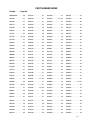
11—— Torque Chart . . . . . . . . . . . . . . . . . . . . . . . . . . . . . . . . . . . . . . . . . . . 22
12—— Parts Section . . . . . . . . . . . . . . . . . . . . . . . . . . . . . . . . . . . . . . . . . . . 24
12.1—— Elevator Panels and Boot . . . . . . . . . . . . . . . . . . . . . . . . . . . . . . . .
12.2—— Chain, paddles, and Sprockets . . . . . . . . . . . . . . . . . . . . . . . . . . . .
12.3—— Hydraulic System. . . . . . . . . . . . . . . . . . . . . . . . . . . . . . . . . . . . . . .
12.4—— Elevator and Conveyor Mount . . . . . . . . . . . . . . . . . . . . . . . . . . . . .
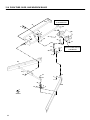
12.5—— Main Frame, Handle, and Link Tube . . . . . . . . . . . . . . . . . . . . . . . .
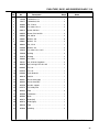
12.6—— Push Tube, Shoe, and Windrow Blade . . . . . . . . . . . . . . . . . . . . . .
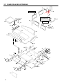
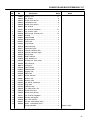
12.7—— Conveyor and Box Extensions. . . . . . . . . . . . . . . . . . . . . . . . . . . . .
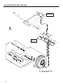
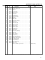
12.8—— Caster Pivot, axle, and Tire . . . . . . . . . . . . . . . . . . . . . . . . . . . . . . .
24
26
28
30
32
34
36
38
1
1 MODELS USED ON
1
MODELS USED ON______________
The Core Harvester accessory, Part No. 4119652, can
be used on Turf Truckster Models 84043, 84044,
84056, 84057, 84061, 898530, 898532, 898543,
898627, 898628, 898630, 898632, 898633, 898634,
898636, 898637, 898650, 898652, 898659, 898662,
898663, 898664, 898684, 898685, 898656, 898657, &
898658. Refer below to see if the Turf Truckster
requires a conversion kit.
2
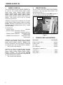
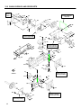
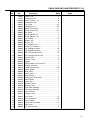
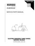
IDENTIFICATION ________________
The part number and serial number of the accessory
are printed on the name plate decal located on the
main frame (See Fig. 1).
The part number and serial number MUST appear on
all correspondence concerning this accessory.
NAME PLATE
DECAL
Installation on small rear tire Cushman Turf Truckster
models 898530, 898532, 898543, 898630, & 898632.
DO NOT install the Core Harvester on any of the small
tire models that are equipped with a cab or a ROPs
(Part No. 892689).
Conversion Kits:
• 891252 Yoke Kit . . . . . . . . . . . . . . . . . . . . Required
• 887933 Auxiliary Transmission Gear Set
. . . . . . . . . . . . . . . . Required for units 8610 and prior
• 888453 Hydraulic Update Kit . . . Required for units
8910 and prior
• 889558 Remote Coupler Kit . . . . Required for units
9010 and prior
Installation on older large rear tire (23 x 13-10) Turf
Truckster models 898530, 898532, 898630, 898632,
898633, 898634, 898636, & 898637. DO NOT install
the Core Harvester on any of the large tire models that
are equipped with a cab or a ROPs (Part No. 892689).
•
No Conversion Kits Required.
Installation on newer Turf Trucksters with large tires
(23 x 13-10) models 898650, 898652, 898659,
898662, 898663, 898664, 898684, 898685, 898656,
898657, & 898658. The Core Harvester CAN BE
installed on any of these models that are equipped with
an upper ROPs (Part No. 894761).
•
No Conversion Kits Required.
2
Figure 1
3
SERVICE PARTS AND MATERIAL _
Description ............................................ Part Number
Paddle, elevator chain ...................................... 832334
Coupler, chain ................................................... 832421
Link, chain......................................................... 832422
Link, attachment................................................ 832423
Turf Protector™ hydraulic oil
2.5 gal. (9.7 L) ..................................................... 65363
5 gal. (18.9 L) ...................................................... 65352
55 gal. (208 L) ..................................................... 65354
SET-UP 1
1
1.1
SET-UP _______________________
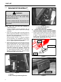
UNPACKING __________________________
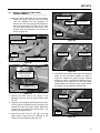
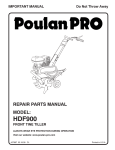
1. Remove the banding strap used to secure the
elevator and loose parts to the pallet. Remove all
loose parts and boxes, except the elevator
assembly, from the shipping pallet. Remove any
banding straps securing the push tube assembly to
the elevator (See Fig. 2).
!
CAUTION
Keep hands and fingers away from pinch points.
Since these parts pivot, it is possible to injure
the hands and/or fingers when raising or rolling
the elevator assembly.
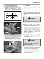
2. Pivot the push tube assembly to the front of the
elevator and allow push tube to rest on floor. Roll
the elevator 180_ so the shock and main pivot
shaft are on the bottom (the shock, main frame
and main pivot shaft will pivot unless they are
secured to the elevator, you may want to attach
banding or straps to these items so they do not
pivot as the elevator is being rolled or raised) (See
Fig. 3).
NOTE: Any reference to the front, back, left or right
side of the vehicle will always be determined
from the operator’s seated position.
3. Remove vehicle left side panel.
4. Remove left hip restraint on Trucksters July, 1998
and prior.
IMPORTANT!
IF YOUR VEHICLE IS EQUIPPED WITH A SHORT
BOX SET AND TAILGATE RELEASE SET, PART NO.
885488, THIS TAILGATE RELEASE MUST BE
REMOVED. IT WILL BE MOVED TO THE RIGHT
SIDE OF SHORT BOX. NOTE POSITION AND
RETAIN ALL PARTS WHEN REMOVING.
1.2
TAILGATE RELEASE INSTALLATION
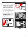
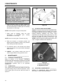
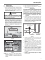
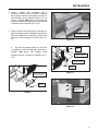
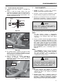
1. Mark the location as shown, lower portion of right
box side panel (See Fig. 4). Drill one 11/32”
(9 mm) diameter hole through box. The bracket
will be in same location as bracket on left side.
Secure with 5/16-18 x 5/8 screw (Part No. 306555)
and flangelock nut (Part No. 548911).
REF. BRACKET 823038
4"(102 mm)
3 3/16"(81 mm)
LIFT & PIVOT THE PUSH
TUBE AND LET IT REST
ON THE FLOOR
REF. BOTTOM OF BOX
PUSH TUBE
Figure 2
SHOWN FOR
REFERENCE ONLY
ROLL THE
ELEVATOR 180_
THE ELEVATOR IS SHIPPED
UPSIDE DOWN, ROLL THE
ELEVATOR TO PROPERLY
INSTALL ON VEHICLE
REF. FRONT
BOX POST
RIGHT SIDE
Figure 4
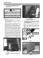
2. Insert plate assembly inside the right front box
post. Secure with existing hardware. Drill holes if
required.
3. Attach handle/pivot holder to existing top holes in
post using existing hardware.
4. Remove the existing tailgate release at right rear of
short box. Install new tailgate release latch (Part
No. 830950). Use existing hardware.
5. Insert the tailgate release rod through bracket on
box. Install bushing, washer, spring and washer
on rod and insert through box post and handle
pivot.
6. Assemble tailgate rod to new latch with flatwasher
and new cotter pin (Part No. 306328).
7. Push front flatwasher back against spring and
insert new cotter pin (Part No. 306328) through
rod.
Figure 3
3
1 SET-UP
1.3
INSTALLING ELEVATOR ASSEMBLY FOR
TRUCKSTERS JULY, 1998 AND PRIOR ____
!
WARNING
The elevator assembly is heavy and requires two
or more people to lift it. Use proper lifting
techniques to avoid injury.
1
2
If a hoist is used to lift the unit, keep feet and
legs out from underneath the elevator while it is
being raised.
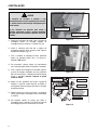
NOTE: Make sure the push tube assembly is
positioned forward.
Loosen hardware securing hydraulic box on
stopwall to gain access to main frame mounting
hardware.
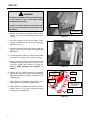
1. Place the main frame upper mounting bracket in
position against the FRONT of vehicle stopwall. At
the same time place lower mounting bracket in
position on vehicle FRAME RAIL.
Use two screws, 5/16-18 x 1 (Part No. 306416),
four flat washers, two lockwashers and nuts to
secure upper mounting bracket to stopwall (See
Fig. 5). Tighten hydraulic box hardware.
2. Raise and support lower end of elevator enough so
lower mounting bracket can be clamped in place
against vehicle frame rail; with bracket top flange
down against top of frame rail. Clamp in place.
Use holes in bracket as a template. Drill four (4)
13/32” (10 mm) holes through frame rail (See Fig.
6). Secure with four screws, 3/8-16 x 1 (Part No.
306414), lockwashers and nuts. Remove clamps
and support at lower end of elevator.
4134
Figure 6
1. Lower Mounting Bracket
2. Vehicle Frame Rail
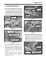
1.4
INSTALLING ELEVATOR ASSEMBLY _____
FOR TRUCKSTERS AUGUST, 1998 AND NEWER
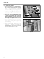
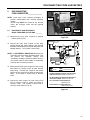
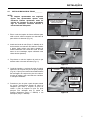
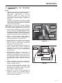
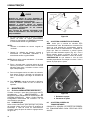
1. Install the black Mount Bracket (Part No. 894698)
to the existing holes in the vehicle frame as shown
in Figure 1. Secure using two (2) M10-1.50 x 30
screws (Part No. 452400) and two (2) M10-1.50
nuts (Part No. 450454) (See Fig. 7 & 8).
PART NO.
450454
MOUNTING BRACKET
PART NO. 894698
PART NO.
452400
Figure 7
1
2
4133
MOUNT BRACKET
Figure 5
1. Stopwall
2. Main Frame Upper Mounting Bracket
4
Figure 8
SET-UP 1
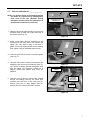
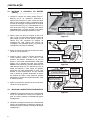
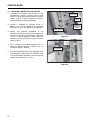
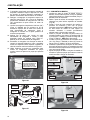
2. Attach the green bracket (Frame-to-ROPS Mount,
Part No. 844797) to the mount bracket as shown in
Figure 3. Secure using two (2) M10-1.50 x 30
screws (Part No. 452400). Do Not tighten, the
hardware will need to remain loose for adjustment
when the elevator is installed (See Fig. 9 & 10).
FRAME-TO-ROPS MOUNT
PART NO. 844797
PART NO.
452400
3. Install the clamping bracket (Part No. 844798) and
clamping plate (Part No. 844668) onto the ROPS
structure just to the left of the hand hold on the left
side of the vehicle (See Fig. 11 & 12).
Figure 9
4. Secure using two (2) M8-1.25 x 25 screws (Part
No. 452389) and M8-1.25 flange nuts (Part No.
450453). Do Not tighten, these will also be
tightened when the elevator is mounted (See Fig.
11 & 12).
FRAME-TO-ROPS
MOUNT
PART NO.
450453
Figure 10
CLAMPING BRACKET
PART NO. 844798
THE ELEVATOR WILL
MOUNT TO THESE
TWO (2) HOLES
CLAMPING PLATE
PART NO. 844668
PART NO.
452389
Figure 11
Figure 12
5
1 SET-UP
!
WARNING
The elevator assembly is heavy and requires two
or more people to lift it. Use proper lifting
techniques to avoid injury.
If a hoist is used to lift the unit, keep feet and
legs out from underneath the elevator while it is
being raised.
FRAME-TO-ROPS
MOUNT
LOWER ELEVATOR
MOUNT BRACKET
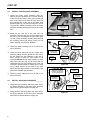
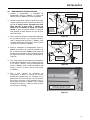
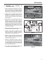
5. Position the elevator so the lower elevator mount
bracket sets on the frame-to-ROPS mount (See
Fig 13).
Figure 13
6. Lean the elevator back until the upper mount
bracket is against the the front of the clamping
plate (See Fig. 14).
7. Secure the elevator to the lower mount using four
(4) M10-1.50 x 70 screws (Part No. 452404). Do
Not tighten.
8. If necessary, place blocks (or equivalent) beneath
the elevator for support while it is being mounted.
9. Secure the upper elevator mount bracket to the
clamping plate using two (2) M8-1.25 x 25 screws
(Part No. 452389) and flange nuts (Part No.
450453). Begin tightening the hardware as
follows:
10. Tighten the two screws securing the clamping
plate and bracket to the top part of the ROPS then,
tighten the hardware securing the elevator to the
clamping plate.
11. Next, tighten the hardware securing the lower
elevator mount to the frame-to-ROPS mount.
Figure 14
PART NO.
452404
CLAMPING PLATE
AND BRACKET
PART NO.
452389
FRAME-TOROPS MOUNT
CORE HARVESTER
MAIN FRAME IS SHOWN
WITHOUT ELEVATOR FOR
REFERENCE ONLY
12. Then, tighten the hardware securing the frame-toROPS mount to the black mounting bracket
secured to the vehicle frame.
PART NO.
452404
Figure 15
6
SET-UP 4
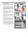
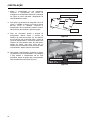
4.5
INSTALL PIPE NIPPLES ________________
PUSH TUBE
NOTE: The photo’s shown in the following figures
are shown as a reference only, although they
show areas of the Core Harvester already
assembled, please follow the instructions as
described and referenced in each step.
NEED TO KEEP PUSH TUBE
HIGH ENOUGH TO CLEAR
THREADED HOLES
PIPE
NIPPLE
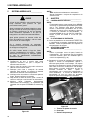
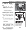
1. Raise the push tube high enough to clear the two
threaded holes on each side of the lower part of
the elevator (See Fig. 16).
Figure 16
2. Install a pipe nipple (Part No. 832430) from the
accessory kit onto each side of the elevator and
tighten (you may want to apply a thin layer of
grease on the pipe nipple threads before installing
them, tighten using an adjustable pipe wrench).
PIPE
NIPPLE
PUSH
TUBE
3. Lower the push tube so it rests on the pipe nipples
(See Fig. 17).
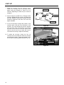
4. The push tube and the caster pivot assembly are
attached to the main pivot pin assembly (See Fig.
18). The pin is already inserted through the push
tube and caster pivot assembly mounts but is
shipped without the washer and cotter pin
attached.
Figure 17
CASTER PIVOT
ASSEMBLY
SECURE END
OF PIVOT PIN
WITH WASHER
AND COTTER PIN
5. Push the pivot pin from the vehicle side, outward
through all bushings securing the caster pivot
assembly and push tube to the main pivot pin.
Secure using one (1) large washer (Part No.
832479) and one cotter pin (Part No. 325109).
MAIN
PIVOT PIN
Figure 18
7
4 SET-UP
4.5
INSTALL CASTER (YOKE) ASSEMBLY ____
1. Locate the caster (yoke) assembly (Part No.
890118) from the accessory kit. Face the opening
of the slots at the bottom of the yoke towards the
front of the vehicle and insert the yoke stem into
the mounting tube at the end of the caster pivot
assembly (See Fig. 19). Secure using one (1) lock
ring (Part No. 548349). Carefully lower the caster
and yoke assembly allowing the yoke to rest on the
floor.
CASTER PIVOT
ASSEMBLY
CASTER YOKE
ASSEMBLY
INSERT YOKE STEM
THROUGH CASTER
PIVOT TUBE
2. Mount the tire and rim to the axle and hub
assembly. The axle and hub will be installed from
the side of the rim opposite the valve stem (See
Fig. 20). Insert the wheel mounting studs through
the mounting holes and secure using four (4)
wheel retaining nuts (Part No. 805860).
Figure 19
HUB AND AXLE
ASSEMBLY
3. Torque the wheel retaining nuts to 70-100 ft. lbs.
(95 to 140 N×m).
4. Install the wheel and axle onto the caster yoke
assembly sliding the axle against the rear side of
the slot. Make sure the hardware on the axle is
loose enough to allow the yoke frame to be
mounted between the two large washers on each
side of the yoke (See Fig. 21) or remove the nut,
lockwasher and one large washer from each end
of the axle, slide the wheel on making sure to keep
one (1) large washer on the inside of the yoke
frame, and one large washer on the outside of the
yoke frame. Replace the hardware.
5. Torque the axle retaining nuts to 70-100 ft. lbs.
(95 to 140 N×m).
4.5
INSTALL ON SIDE
OF RIM OPPOSITE
THE VALVE STEM
FRONT OF
VEHICLE
VALVE STEM
Figure 20
CASTER YOKE
ASSEMBLY
MAKE SURE THERE IS A LARGE
WASHER ON THE INSIDE AND
OUTSIDE OF THE YOKE FRAME
ON THE OPPOSITE SIDE ALSO
LARGE WASHER
ON OUTSIDE OF
YOKE FRAME
LARGE WASHER
ON INSIDE OF
YOKE FRAME
INSTALL AIR SHOCK ABSORBER________
1. Using hardware provided, attach the lower end of
the shock absorber to the caster pivot assembly
stud (Refer to parts illustration on page 30).
2. Using hardware provided, attach the upper end of
the shock absorber to the main frame assembly
stud (Refer to parts illustration on page 30).
8
WHEEL
RETAINING NUT
SLIDE AXLE
AGAINST THE BACK
OF THE SLOT
Figure 21
SET-UP 4
4.5
INSTALL LOWER LINK AND UPPER
TENSION SPRINGS ____________________
1. Raise and support the lower end of the elevator.
Locate the 10 5/8” (270 mm) lower link spring
(Part No. 832525) from the accessory kit.
Connect one end of the spring to the bracket on
the lower link as shown in Figure 22 (the lower
link is located towards the lower front of the
elevator near the floorboard of the vehicle as
shown in Figure 23).
LOWER LINK SPRING
(10 5/8" (270 mm) LONG)
ADJUSTING
SCREW
NUT ON EACH SIDE OF
OVER-CENTER BRACKET
FRONT OF
VEHICLE
CONNECT TO BRACKET
ON LOWER LINK
LOWER LINK
Figure 24
LOWER LINK SPRING
[10 5/8" (270 mm) LONG]
UPPER
TENSION SPRING
FRONT OF
VEHICLE
SPRING MOUNT BAR
ON UPPER LINK
AS VIEWED FROM
THE PASSENGER SIDE OF VEHICLE
Figure 22
THE BRACKET ON THE
LOWER LINK IS LOCATED ON
THE SIDE OF THE ELEVATOR
FACING THE VEHICLE
THE LOWER LINK SPRING
IS SHOWN INSTALLED
TO REFERENCE IT'S LOCATION
Figure 23
2. Connect the other end of the spring to the
adjusting screw on the over-center bracket (See
Fig. 24).
3. Using the screw (Part No. 832438) and two (2) 3/816 nuts (Part No. 304632) from the Accessory Kit,
install them to the over-center bracket. Make sure
to keep one nut on each side of the bracket. The
spring will be adjusted later.
4. Connect one end of the 15 3/8” (391 mm) long
upper tension spring (Part No. 832322) to the
mount bar on the upper link (See Fig. 25).
Figure 25
5. Connect the other end of the spring to the adjusting
screw on the over-center bracket as shown in
Figure 26. Remove the screw (Part No. 832438)
and two (2) 3/8-16 nuts (Part No. 304632) from the
Accessory Kit and install them to the over-center
bracket. Make sure to keep one nut on each side of
the bracket. The spring will be adjusted later.
ADJUSTING
SCREW
UPPER TENSION SPRING
[15 3/8" (391 mm) LONG]
NUT ON EACH SIDE OF
OVER-CENTER BRACKET
FRONT OF
VEHICLE
Figure 26
9
4 SET-UP
4.5
INSTALL LIFT HANDLE _________________
1. The lift handle will mount to the shaft directly in
front of the over-center bracket (the over-center
bracket is the same bracket the two adjusting
screws and springs were previously attached to).
LIFT
HANDLE
ATTACH
SPRING
2. Locate the lift handle (Part No. 888271) and the
small handle spring (Part No. 812368) from the
Accessory Kit.
3. Apply a small amount of a lithium-based lubricant
to the lift handle mounting shaft and slide the
handle onto the shaft. The bracket welded on the
bottom of the handle will face towards the front of
the vehicle (See Fig. 27).
SLIDE HANDLE
ONTO SHAFT
OVER-CENTER
BRACKET
Figure 27
4. Secure the lift handle using one (1) retaining
washer (Part No. 548165) and one (1) cotter pin
(Part No. 304635).
LIFT
HANDLE
5. Attach one end of the handle spring to the
mounting tab at the bottom of the handle and
attach the other end of the spring to the hole on the
over-center bracket (See Fig. 27 & 28).
Figure 28
10
SET-UP 4
4.5
CONVEYOR MOUNTING ________________
1. Locate the conveyor, conveyor mount (Part No.
894845) and stake bracket (Part No. 888274) from
the accessory kit.
2. Place the stake bracket into the stake holder at the
rear of the left box-side (See Fig. 29). If your
vehicle is equipped with a box other than the
short box, the stake bracket will be installed
into the middle stake holder (the stake holder will
actually be closer to the rear than to the center of
the box).
3. Secure the stake bracket to the side-box using one
(1) 3/8-16 x 2 1/2” screw (Part No. 301431), one
(1) 3/8 flat washer (Part No. 306981), one (1) 3/8
lockwasher (Part No. 120177) and one (1) 3/8-16
nut (Part No. 306562).
STAKE BRACKET
LEFT REAR
STAKE HOLDER
(SHORT BOX)
STAKE
HOLDER
(LARGE BOX)
Figure 29
CONVEYOR MOUNT
PART NO. 894845
4. Install the conveyor mount (Part No. 894845), by
placing the short 90_ end-tube into the front stake
holder on the left side-box and positioning the
horizontal tube in the yoke on the stake bracket as
shown in Figure 30.
5. Secure the front side of the conveyor mount to the
side-box using one (1) 3/8-16 x 2 1/2” screw (Part
No. 301431), one (1) 3/8 flat washer (Part No.
306981), one (1) 3/8 lockwasher (Part No. 120177)
and one (1) 3/8-16 nut (Part No. 306562).
PLACE
END OF MOUNT
INTO YOKE
TO
FRONT, LEFT
STAKE HOLDER
Figure 30
6. Secure the rear side of the conveyor mount, to the
yoke on the stake bracket previously installed (See
Fig. 31). Insert one (1) 3/8-16 x 2 3/4” screw (Part
No. 307776) through the holes in the yoke and
secure using one (1) 3/8 flat washer (Part No.
306981), one (1) 3/8 lockwasher (Part No. 120177)
and one (1) 3/8-16 nut (Part No. 306562).
SHORT BOX SHOWN
INSTALLATION WILL BE THE SAME
ON THE LARGER BOX,
ONLY DIFFERENCE WILL BE THE
LOCATION OF THE STAKE HOLDER
Figure 31
11
4 SET-UP
7. Mount the conveyor onto the conveyor mount.
Position the conveyor onto the conveyor mount
plates using the illustration in Figure 32 as a
reference depending on which box your vehicle is
equipped.
LARGE BOX
8. Secure using four (4) M8-1.25 x 25 flange screws
(Part No. 452389) and four (4) M8-1.25 flange nuts
(Part No. 450453). Position the conveyor until the
screws are against the rear side of the slots and
tighten hardware.
SHORT BOX
9. It may be necessary to adjust the position of the
conveyor while using the Core Harvester for the
first time. The cores should drop from the elevator
onto the center of the conveyor belt. It is common
for some of the cores to hit off the sides of the
chute as well, but you do not want the cores to
over-shoot the conveyor. Adjust as necessary.
Figure 32
10. To adjust the conveyor, loosen the four (4)
conveyor-to-mount screws and slide the conveyor
to the desired location. Tighten the hardware once
the conveyor is properly positioned (See Fig. 33).
CONVEYOR
CONVEYOR MOUNT
Figure 33
12
SET-UP 4
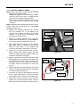
4.11 ROUTING HYDRAULIC HOSES ___________
NOTE: Apply Teflon Pipe Thread Tape to all thread
joints on the hydraulic system.
Do Not over-tighten the hydraulic fittings. Tighten
joints until they do not leak, over-tightening the
joints can cause fitting damage and leaks.
Route hose so they clear parts that move and/or
get hot. Use wire ties to keep the hoses secured
in position.
Wipe all hydraulic fitting threads (male ends as well as
female ends) with a clean (lint free) cloth before
applying the Teflon tape.
1. Install the 90_ hydraulic fitting (Part No. 827395)
from the Accessory Kit, to the back of the
conveyor motor. Tighten the fitting so the hose
connector is facing down and slightly turned
towards the box (See Fig. 34).
2. Install the straight hydraulic fitting (Part No.
832396) from the Accessory Kit, to the bottom of
the conveyor motor and tighten (See Fig. 34).
90_ FITTING
PART NO. 827395
STRAIGHT FITTING
PART NO. 832396
NIPPLE
PART NO. 105706
3. Apply Teflon tape to the threads of the hydraulic
pipe nipple (Part No. 105706) from the Kit, and
install the pipe nipple to the straight fitting
previously connected to the bottom of the motor.
DRYSEAL COUPLER
PART NO. 894701
4. Locate one (1) dryseal female coupler (Part No.
894701) from the Kit. Install the coupler to the end
of the pipe nipple previously installed (make sure
Teflon tape is applied to the nipple).
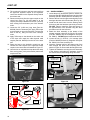
5. Apply a couple turns of new Teflon tape to the hose
end and install one (1) hydraulic male coupler (Part
No. 894702) from the Kit. Route the hose to the
conveyor motor and connect the male coupler to
the female coupler on the bottom of motor (See
Fig. 35).
6. Apply Teflon tape to the threads of the 45_ fittings
(Part No. 521949) and install and secure fittings to
the elevator motor (See Fig. 35).
7. Locate the 30” (762 mm) long hydraulic hose from
the Kit , apply Teflon tape to one end of the hose
and install it to the 45_ fitting on the elevator motor.
8. Apply Teflon tape to the other end of the hose.
Locate one (1) dryseal female coupler (Part No.
894701) from the Kit and install it on the hose end.
Figure 34
CONVEYOR
MOTOR
ELEVATOR
MOTOR
45_
FITTING
FEMALE COUPLER
PART NO. 894701
MALE COUPLER
PART NO. 894702
Figure 35
13
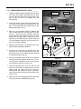
4 SET-UP
9. The coupler will connect to the hose removed from
the upper-left hydraulic coupler on the hydraulic
control box located on the stopwall directly behind
the drivers seat.
10. Disconnect the hose from the upper coupler on the
control box (See Fig. 36) and attach it to the
coupler previously installed onto the 30” (762 mm)
hose coming from the bottom port of the elevator
motor.
11. Locate the 56” (1422 mm) long hose (Part No.
832398) from the Accessory Kit. Apply Teflon tape
to the threads on one end of the hose. Connect the
hose to the 90_ fitting on back of the conveyor
motor.
12. Apply Teflon tape to the threads on the other end
of the hose and install the other dryseal male
coupler (Part No. 894702) from the kit to the hose
end.
13. Route the hose to the hydraulic control box and
connect the male coupler to the upper-left female
coupler in the control box as illustrated in Figure 37.
14. Use wire ties or equivalent to keep the hoses away
from moving parts, pinch points and/or parts which
may become hot.
4.11 SHOE ASSEMBLY______________________
1. Locate the two (2) shoe braces (Part No. 832391, left
brace and Part No. 832392 right brace) and the shoe
assembly (Part No. 887963) from the Accessory Kit.
2. Remove the nut from the upper mounting hole on the
bearing at the lower left of the elevator (See Fig. 38).
3. Install the left shoe brace onto the bearing screw
and secure with the hardware previously removed.
DO NOT Tighten. Install the right shoe brace on
the opposite side of the elevator using the same
procedure used for the left brace.
4. Attach the shoe assembly to the bottom of the
elevator securing it with four (4) 5/8-18 x 5/8 screws
(Part No. 306555) and 5/8-18 flangelock nuts (Part
No. 548911). DO NOT tighten hardware at this time.
5. Locate the two (2) 5/16-18 x 3/4 carriage bolts
(Part No. 800358) and two (2) flangelock nuts (Part
No. 548911) from the Accessory Kit.
6. Insert the carriage bolt from the bottom side of the
shoe through the shoe brace mounting hole as
shown in Figure 39. Secure with the flangelock nuts.
7. Tighten the hardware securing the shoe assembly
to the elevator and tighten the hardware securing
the shoe braces to the bearing flange and shoe.
REMOVE UPPER NUT
ON BEARING FLANGE
AND INSTALL BRACE
DISCONNECT HOSE FROM
UPPER COUPLER ON CONTROL BOX
AND ATTACH
TO THE COUPLER ON THE
30" (762 MM) HOSE
SECURE
HERE
LEFT SIDE
SHOE BRACE
SECURE
HERE
SHOE
ASSEMBLY
Figure 38
Figure 36
ELEVATOR
MOTOR
30" HOSE
(762 mm)
CONVEYOR
MOTOR
CARRIAGE
BOLT
56" HOSE
(1422 mm)
Figure 37
14
Figure 39
SET-UP 4
4.11 CORE WINDROW INSTALLATION_________
PIVOT PIN ON
PUSH TUBE
1. Install the windrow (blade) assembly onto the push
tube. Slide the windrow assembly onto the push
tube pivot pin as shown in Figure 39. Secure using
one (1) hair pin (Part No. 809265) from the
Accessory Kit.
2. Locate the blade tie plate (Part No. 832309) from
the Accessory Kit. Align the mounting tabs on the
ends of the blades with the outside holes on the
blade tie plate (See Fig. 41).
WINDROW
ASSEMBLY
3. Slide one (1) flat washer (Part No. 306981) and
one (1) bushing (Part No. 521679) onto one of the
3/8-16 x 1 screws (Part No. 306414), Insert the
screw w/washer and bushing (from the top side)
through the mounting holes on either the left or
right side of the blade tie plate. Secure using one
(1) 3/8 lockwasher (Part No. 120177) and one (1)
3/8-16 nut (Part No. 306562).
4. Repeat this procedure on the opposite side of the
blade tie plate and tighten hardware.
PUSH TUBE
Figure 40
TIE ROD
PART NO.
832310
SUPPORT
BRACKET
MOUNT TAB
ON BLADE
ASSEMBLY
BLADE TIE
PLATE
PART NO.
832309
5. Locate the tie rod (Part No. 832310) from the
Accessory Kit. Insert the threaded end of the rod
through the hole on the support bracket attached
to the push tube (See FIg. 41).
6. When the threaded section of the tie rod passes
through the bracket support, thread one (1) 7/1614 nut (Part No. 304364) onto the tie rod until the
nut contacts the shoulder on the tie rod.
Figure 41
HAIR PIN
7. Insert the threaded end of the tie rod into the
center hole of the blade tie plate (See Fig. 41) and
secure using the other 7/16-14 nut, Part No.
304364 (when the hardware is secure, the bottom
side of the second nut should be flush with the end
of the tie rod).
8. Secure the tie rod to the support bracket using one
(1) hair pin (Part No. 822529) (See FIg. 42).
Figure 42
15
5 HYDRAULIC SYSTEM
5
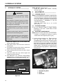
HYDRAULIC SYSTEM ____________
!
WARNING
Escaping hydraulic oil under pressure canhave
sufficient force to penetrate the skin, causing
serious injury.
After assembly of hydraulic system and before
starting vehicle engine to apply pressure to system, make sure connections are tight, hoses
and fittings are not damaged.
NOTE: DO NOT overfill reservoir.
Screw the dipstick and breather assembly
securely in place.
6
ADJUSTMENTS _________________
6.1
LEVELING VEHICLE ____________________
NOTE: 55 PSI MINIMUM air pressure is required in the
air shock at all times to prevent structural damage
to the Turf Truckster. Inflate the air shock enough
to level the vehicle with operator in seat and Core
Harvester attached.
MAXIMUM is 150 PSI
(1034 kPa) air pressure.
Inflate the caster wheel tire to 10 - 12 PSI
(69 - 82 kPa).
6.2
After applying pressure to system, use a pieceof
cardboard or wood, not your hands, to check for
leaks.
If system requires repair, make sure pressureis
relieved before disconnecting hoses.
If injured by escaping fluid, see a doctor atonce.
Serious infection or reaction can develop if
proper medical treatment is notadministered
immediately.
9. Make sure vehicle is on a level surface and
elevator assembly is down.
10. Start vehicle engine, raise and lower vehicle box
several times.
11. Pull upward on selector valve knob to operate the
elevator and conveyor hydraulic motors.
12. Check all fittings and connectors for leaks. Repair
as needed.
13. Lower the vehicle box, stop vehicle engine and
check the reservoir oil level.
14. Add Ransomesr Turf Protectort Biodegradable
hydraulic fluid or equivalent until oil shows on the
KNURLED portion of the dipstick (See Fig. 43).
EXTENSION BOARDS __________________
15. Cut the extension boards to length required,
depending on box used. Install boards in stake
pocket brackets.
6.3
ADJUSTING CONVEYOR BELT ___________
NOTE: Remove curved shield from front of conveyor.
If shield is not installed as received, it must be
installed after belt is adjusted (See Fig. 44).
16. Loosen bearing mounting nuts. Tighten conveyor
belt only tight enough to rotate the belt.
Overtightening will add to torque required to rotate
belt and shorten life of belt lacing. After adjusting
belt, make sure the belt is centered in the trough.
Make centering adjustments with the conveyor belt
rotating slowly. The belt will move away from the
end of belt roller being tightened. Tighten bearing
mounting nuts.
3
2
1
3150
HYDRAULIC
RESERVOIR DIPSTICK
KNURLED PORTION
OF DIPSTICK
SHOWN AS
REFERENCE ONLY
Figure 43
16
Figure 44
1. Belt Adjusting Rods
2. Shield
3. Shield Slot
OPERATION 7
6.4
TENSION SPRING ADJUSTMENT _________
17. Vehicle must be level and elevator down.
18. Adjust the lower tension spring (See Fig. 46) by
adjusting spring adjuster screw so an equal
amount is on each side of the frame bracket as
shown. Lock in place with nuts (See Fig. 45).
ADJUSTER
SCREW
OPERATION ____________________
1. BEFORE using vehicle with attachment, place
vehicle on level surface.
2. Check the vehicle, as viewed from front to make
sure it is level.
3. Add air, 55 PSI-150 PSI (379 to 1034 kPa) to the
air shock as required, to level vehicle with operator
in seat.
REF.
FRAME
BRACKET
!
NUT
NUT
7
WARNING
Bodily injury can occur when air shock pressure
exceeds 150 PSI (1034 kPa).
Figure 45
Inflate caster wheel tire to 10-12 PSI (69-82 kPa).
ADJUSTING
SCREWS
UPPER
TENSION
SPRING
LOWER
TENSION
SPRING
Figure 46
19. Next adjust the upper spring adjuster screw (See Fig.
46) until 30 to 40 pounds is required to lift the lower
end of elevator with a spring scale (See Fig. 47).
20. Raise the elevator assembly using the lift handle.
The handle MUST go “overcenter” with positive
action.
NOTE: Failure to maintain 55 PSI MINIMUM air
pressure in air shock at all times, can cause
structural damage to the Turf Truckster.
4. Install the windrow (blade assembly) using
CENTER mounting holes when gathering cores in
a straight line such as back and forth across a
green or on fairways. For circular patterns, use
RIGHT
mounting
holes
for
COUNTERCLOCKWISE travel, LEFT mounting
holes for CLOCKWISE travel.
NOTE: ALWAYS remove the windrow (blade
assembly) when transporting long distances. For
short distances, use lift handle to raise elevator to
overcenter position.
!
WARNING
Failure to remove windrow assembly before
ransporting long distances can result in the
raised extended blades hitting objects or
bystanders resulting in injury.
CHECK
TENSION
HERE
NOTE: Also the added weight of the windrow blades
increase the shock loading to Core Harvester and
vehicle when traveling over rough ground.
5. Pull upward on remote hydraulics (selector valve)
knob to start elevator and conveyor rotation. Push
knob down to return the hydraulic system to
standard hydraulic functions.
Figure 47
17
8 MAINTENANCE
!
LOWER
LINK
WARNING
FITTING
Keep body parts out of elevator opening and
away from conveyor when machine is operating.
ALWAYS depress (push knob down) remote
hydraulic control, and shut off vehicle engine
BEFORE doing maintenance or freeing
obstructions from the elevator.
A jammed elevator chain can suddenly break
free and injure a person working on it.
6. While harvesting cores on greens, operate the
vehicle at the recommended engine RPM. Place
the drive transmission in FIRST gear and auxiliary
transmission in LOW range.
NOTE: Reduce speed on rough or steep terain.
7. When used on fairways, place the drive
transmission in SECOND gear, auxiliary
transmission in LOW range.
NOTE: Never use other gears. Elevator may clog.
FITTING
FITTING
CASTER
PIVOT ARM
Figure 48
8.3
ELEVATOR CHAIN ADJUSTMENT _________
DO NOT let elevator chain become excessively loose.
Normally an adjustment will be needed at the upper
drive sprocket after each 8 hours of operation. Loosen
bearing attaching hardware and make equal
adjustments at each upper bearing (See Fig. 49). With
the cover off, adjust the chain so that there is 3” of
deflection measured at the center of the chain. BE
SURE to keep the sprocket shaft perpendicular to the
chain. Retighten hardware after adjustment.
8. Raise the elevator to overcenter position and
depress remote hydraulic control to stop elevator
when making turns after each pass.
9. For minimum wear on the elevator boot, always
lower the elevator to the ground when dumping a
load of cores.
2
1
10. ALWAYS stop elevator rotation and shut off
vehicle engine before leaving operator’s seat.
8
MAINTENANCE _________________
8.1
HYDRAULIC RESERVOIR OIL ____________
Refer to section 5 for FILLING HYDRAULIC
RESERVOIR AND CHECKING HYDRAULIC SYSTEM
for the procedure. Use Ransomes® Turf Protector™
Biodegradable hydraulic fluid or an equivalent
hydraulic oil.
8.2
Figure 49
1. Bearing and Hardware
2. Adjustment Screws
LUBRICATION _________________________
Use a lithium base pressure gun grease at the three
(3) grease fittings every 20 hours of operation. Refer
to the caster pivot arm and the lower link shown in
figure 48.
18
3153
8.4
ADJUSTING CONVEYOR BELT ___________
REFER TO CONVEYOR BELT ADJUSTMENT
SECTION 6.3 FOR THIS ADJUSTMENT.
DISCONNECTING CORE HARVESTER 9
9
DISCONNECTING
CORE HARVESTER______________
NOTE: Clean hose quick couplers thoroughly to
prevent contaminants from entering hydraulic
system.
Closed loops MUST be formed at the elevator
motor, the conveyor motor and the stopwall
bracket.
9.1
FEMALE
COUPLER
MALE
COUPLER
REFER
TO
DECAL
DISCONNECT AND RECONNECT
QUICK COUPLERS AS FOLLOWS ________
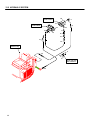
11. Disconnect the two quick couplers at stopwall
bracket (See Fig. 50).
12. Connect the male quick coupler on the hose
coming through the snap bushing in the stopwall
bracket to the female quick coupler attached to the
stopwall bracket. This creates a closed loop.
STOPWALL
BRACKET
Figure 50
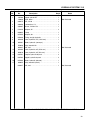
TRUCKSTER
CYLINDER
MOTOR DRIVEN
ACCESSORY
10
7
LIFT
VALVE
1
4
9
2
5
8
NOTE: It is EXTREMELY IMPORTANT that these two
hoses are connected at the stopwall bracket. This
will prevent the hydraulic system from
overheating, leading to hydraulic system failure, if
the remote selector valve handle is accidentally
pulled up with accessory removed.
3
6
SELECTOR
VALVE
HYDRAULIC
TANK
13. Disconnect the male quick coupler on hose coming
from bottom of conveyor motor, to lower elevator
motor fitting. Connect this coupler to the female
coupler on hose coming from upper elevator motor
fitting. This creates a closed loop at elevator
motor.
HYDRAULIC
PUMP
PRESSURE
SUCTION
RETURN
PRESSURE OR RETURN
ACCESSORY
CYLINDER
FOR MOTOR DRIVEN ACCESSORY AND TRUCKSTER
DUMP BOX OPERATION: PLUG 1-4, 2-3, 8-9, 7-10.
FOR MOTOR DRIVEN ACCESSORY AND INOPERABLE
TRUCKSTER CYLINDER: PLUG 1-2, 3-4, 8-9, 7-10.
14. Connect the male coupler on hose coming from
rear of conveyor motor to coupler on bottom of
conveyor motor. This creates a closed loop at
conveyor motor (Refer to Fig. 51).
FOR TRUCKSTER CYLINDER OPERATION:
PLUG 1-4, 2-3, 7-8.
FOR ACCESSORY CYLINDER OPERATION:
PLUG 1-5, 2-6, 4-3, 7-8.
Figure 51
19
10 EC CONFORMITY CERTIFICATE
10
EC CONFORMITY CERTIFICATE __________________________________________
DECLARATION OF INCORPORATION PROHLÁENÍ O ZALOENÍ SPOLENOSTI INKORPORERINGSERKLÆRING INCORPORATIEVERKLARING KINNITUS ÜHENDAMISE KOHTA ASENNUSTODISTUS DECLARATION DINCORPORATION EINBAUBESCHEINIGUNG BEÉPÍTÉSI NYILATKOZAT DICHIARAZIONE DI INCORPORAZIONE NOFORMANAS DEKLARCIJA PRIJUNGIMO DEKLARACIJA DIKJARAZZJONI
TA INKORPORAZZJONI DEKLARACJA ZGODNO!CI DLA PODZESPO"U DECLARAÇÃO DE INCORPORAÇÃO DECLARA#IE DE ÎNCORPORARE VYHLÁSENIE O
ZABUDOVANÍ SÚASTI IZJAVA ZA VGRADNJO DECLARACIÓN DE INCORPORACIÓN INBYGGNADSDEKLARATION
Business name and full address of the manufacturer Obchodní jméno a plná adresa výrobce Producentens firmanavn og fulde adresse Bedrijfsnaam en volledig adres van de fabrikant Tootja ärinimi ja täielik aadress Valmistajan toiminimi ja täydellinen osoite Nom commercial et adresse complète du fabricant Firmenname und vollständige Adresse des Herstellers !"#$%& #'()*+ !*'*!& A gyártó üzleti neve és teljes címe Ragione sociale e indirizzo completo del fabbricante Uz,-muma nosaukums un pilna raot/ja adrese Verslo pavadinimas ir pilnas gamintojo adresas Isem kummer0jali u indirizz s1i1 tal-fabbrikant Nazwa firmy i pe3ny adres producenta Nome da empresa e endereço completo do fabricante Denumirea comercial4 5i adresa complet4 a produc4torului Obchodný názov a úplná adresa výrobcu Naziv podjetja in polni naslov proizvajalca Nombre de la empresa y dirección completa del fabricante Tillverkarens företagsnamn och kompletta adress
Jacobsen, A Textron Company
11524 Wilmar Blvd.
Charlotte, NC 28273, USA
Description and identification of the partly completed machinery. ? @
E GG K K. Popis a identifikace LásteLnM dokonLeného strojního zaQízení. Beskrivelse og identifikation af den delvist fremstillede maskine. Beschrijving en identificatie van de gedeeltelijk voltooide machinerie. Osaliselt komplekteeritud masina kirjeldus ja määratlus. Osittain kootun laitteiston kuvaus ja määrittely. Description et identification de la quasi-machine. Bezeichnung und Identifizierung der teilgefertigten Vorrichtung X'$Y$Z& $%*#%$*[\ +!']%(\ +"&!%\. A részlegesen megépített gép leírása és meghatározása. Descrizione e identificazione della quasi-macchina Da ^-ji pabeigtas iek/rtas apraksts un identifik/cija. Dalinai ubaigtos _rangos apraymas ir identifikacija. Deskrizzjoni u identifikazzjoni tal-makkinarju li jkun lest parzjalment. Opis i oznaczenie cz{|ciowo uko}czonego urz~dzenia Descriç ão e identificação do equipamento parcial Descrierea 5i identificarea echipamentului finalizat parial Opis a identifikácia podzostavy strojného zariadenia Opis in identifikacija delno dokonLanega stroja. Descripción e identificación de la maquinaria parcialmente completada. Beskrivning och identifiering av maskindelarna.
Product Code
Serial Number
Description
4119652
411965202700 - 411965203500
Core Harvester
2701650
270165002000 - 270165003000
Top Dresser 1500
2701600
270160002000 - 270160003000
Vicon Spreader
We undertake to transmit, in response to a reasoned request by the national authorities, relevant information on the partly completed machinery. This shall be by hardcopy and shall be without prejudice to the intellectual property rights of the
manufacturer of the partly completed machinery.
, E , @E GG K K.
G K GG K K.
Zavazujeme se na základM zdvodnMné ádosti ze strany národních úQad poskytnout pQísluné informace o LásteLnM dokonLeném strojním zaQízení. Informace budou pQedány v titMné podobM a nepokodí práva k duevnímu vlastnictví výrobce
týkající se LásteLnM dokonLeného strojního zaQízení.
Som svar på en begrundet anmodning fra de nationale myndigheder forpligter vi os til at videregive oplysninger om den delvist fremstillede maskine. Dette bliver gjort i papirudgave og med forbehold for de immaterielle rettigheder, som indehaves af
producenten af den delvist fremstillede maskine.
We zijn van plan, in reactie op een redelijk verzoek van de nationale autoriteiten, relevante informatie over de gedeeltelijk voltooide machinerie te verzenden. Dit wordt gedaan in de vorm van fysieke kopieën en deze kopieën zullen onder alle
voorbehoud behoren tot de intellectuele eigendomsrechten van de fabrikant van de gedeeltelijk voltooide machinerie.
Me kohustume riigisiseste asutuste põhjendatud nõudmisel edastama asjakohast teavet osaliselt komplekteeritud masina kohta. Andmed edastatakse paberkandjal ning sellega ei tohi piirata osaliselt komplekteeritud masina tootja õigusi intellektuaalsele
omandile.
Sitoudumme toimittamaan osittain koottua laitteistoa koskevat olennaiset tiedot vastineena kansallisten viranomaisten perusteltuun pyyntöön. Tiedot toimitetaan paperitulosteena. Ne eivät rajoita valmistajan osittain koottua laitteistoa koskevia
immateriaalioikeuksia.
Nous nous engageons à fournir, en réponse à une demande rationnelle des autorités nationales, toute information appropriée concernant la quasi-machine. Ceci se fera par copie papier et sans préjuger des droits de propriété intellectuelle du fabricant
de la quasi-machine.
Wir verpflichten uns, auf eine begründete Aufforderung durch die nationalen Behörden hin, relevante Informationen über die teilgefertigte Maschine zu übersenden. Diese werden als Ausdruck übersandt und dürfen sich nicht nachteilig auf die Rechte
am geistigen Eigentum des Herstellers der teilgefertigten Maschine auswirken.
]%' '!*%', $%\ !+*+ '(]%Y+\ !+*+\ ! ') $", !\ *"'!\ ]+$%Z%$'\ [*% Z%$ !% +!']\ +"+. ![ ) $' Y' Y$!\ #"\ )Y' ! '! #! !% !*'*!&
!% +!']%(\ +"&!%\.
Vállaljuk, hogy átadjuk a nemzeti hatóságok megalapozott kérésére válaszul a részlegesen megépített gépre vonatkozó információkat. Az információkat nyomtatott példányban adjuk át. A nyomtatott példány átadása a részlegesen megépített gép
gyártójának szellemi tulajdonjogaira tett kötelezettség nélkül történik.
Ci impegniamo a trasmettere, in risposta ad una richiesta adeguatamente motivata delle autorità nazionali, informazioni pertinenti sulla quasi-macchina. Limpegno sarà redatto in forma cartacea e lascerà impregiudicati i diritti di proprietà intellettuale del
fabbricante della quasi-macchina.
Atsaucoties uz pamatotu valsts iest/u pieprasjumu, m-s ap,emamies nodot saistto inform/ciju par da^-ji pabeigtu iek/rtu. T/ bs ciet/ kopija un nerads kait-jumus da^-ji pabeigt/s iek/rtas raot/ja intelektu/l/ pauma tiesb/m.
Atsakydami _ nacionalini valdios organ uklaus~, pateikiame informacij~ apie dalinai ubaigtus mechanizmus. is dokumentas yra atspausdintas elektroninio originalo variantas ir be jokio iankstinio nusistatymo neturi tikslo paeisti dalinai ubaigto
mechanizmo gamintojo intelektualins nuosavybs teisi.
A1na nwieg1du li nippreentaw, meta mitlubin mill-awtoritajiet nazzjonali, l-informazzjoni relevanti dwar il-makkinarju li jkun lest parzjalment. Din l-informazzjoni g1andha tkun fforma stampata u ming1ajr preudizzju g1ad-drittijiet tal-proprjetà intelletwali
tal-fabbrikant tal-makkinarju li jkun lest parzjalment.
Na uzasadnion~ pro|b{ instytucji pa}stwowych zobowi~zujemy si{ do przekazania wszelkich informacji na temat cz{|ciowo uko}czonego urz~dzenia. B{d~ one przekazane na pi|mie. Strona przekazuj~ca w/wym. dokumentacj{ nie b{dzie ro|ci3a sobie
adnych praw do w3asno|ci intelektualnej producenta cz{|ciowo uko}czonego urz~dzenia.
Na sequência de pedido razoável por parte das autoridades nacionais, comprometemo-nos a transmitir informações importantes sobre o equipamento parcial. Tal será feito por meio de hardcopy
e sem prejuízo para os direitos de propriedade intelectual do fabricante do equipamento parcial.
Ne angaj4m s4 transmitem, ca r4spuns la o solicitare motivat4 a autorit4ilor naionale, informaii relevante privind echipamentul finalizat parial. Aceasta se va efectua în format hârtie 5i f4r4 a aduce atingere drepturilor de proprietate intelectual4 ale
produc4torului echipamentului finalizat parial.
Zaväzujeme sa, e na základe odôvodnenej poiadavky národných orgánov predloíme dôleité informácie o podzostave strojného zariadenia.
Musí to by v tlaLenej forme a bez ujmy na právach duevného vlastníctva výrobcu podzostavy strojného zariadenia.
Zavezujemo se, da bomo na utemeljeno zahtevo nacionalnih organov predloili zadevne informacije o delno dokonLanem stroju. Informacije bodo v tiskani obliki in ne bodo posegale v pravice intelektualne lastnine proizvajalca delno dokonLanega stroja.
Nos comprometemos a transmitir, en respuesta a una petición razonada por parte de las autoridades nacionales, información relevante sobre la maquinaria parcialmente completada. Ésta será transmitida en copia impresa y no afectará a los derechos
de propiedad intelectual del fabricante de la maquinaria parcialmente completada.
Vi åtar oss att vidarebefordra relevant information om maskindelarna vid en motiverad förfrågan från nationella myndigheter. Informationen ska erhållas i form av papperskopior och ska vara utan men för maskindelstillverkarens immateriella rättigheter.
20
Partly completed machinery must not be put into service until the final machinery into which it is to be incorporated has been declared in conformity with the provisions of Directive 2006/42/EC.
G K K
, K, , 2006/
42/E?.
ásteLnM dokonLené zaQízení nesmí být uvedeno do provozu, dokud koneLné zaQízení, do kterého bylo uvedené zaQízení namontováno, neodpovídá ustanovením SmMrnice L. 2006/42/EC.
Delvist fremstillede maskiner må ikke indsættes i driften, før den endelige maskine, som den skal inkorporeres i, er blevet erklæret I overensstemmelse med bestemmelserne i Direktiv 2006/42/EF.
Gedeeltelijk voltooide machinerie mag niet in dienst worden genomen, totdat er voor de definitieve machinerie, waarvan gedeeltelijk voltooide machinerie onderdeel uitmaakt, een conformiteitsverklaring
is ontvangen onder de voorwaarden van Richtlijn 2006/42/EG.
Osaliselt komplekteeritud masinat ei tohi kasutusele võtta enne, kui lõplikult komplekteeritud masin, millega see ühendatakse, on tunnistatud direktiivi 2006/42/EÜ sätetele vastavaks.
Osittain koottua laitteistoa ei saa ottaa käyttöön, ennen kuin lopullinen laitteisto, johon se asennetaan, on vakuutettu direktiivin 2006/42/EY säännösten mukaiseksi.
La quasi-machine ne doit pas être mise en service avant que la machine finale dans laquelle elle doit être incorporée nait été déclarée conforme aux dispositions de la directive 2006/42/CE
Die teilgefertigte Vorrichtung darf erst in Betrieb genommen werden, wenn die Konformität der Maschine, in die sie eingebaut wird, entsprechend den Bestimmungen der Richtlinie 2006/42/EG erklärt
worden ist.
¢ $' '!']'*!' *$\ *!% +!']\ +"+ "$ !% !'][ +"+ *!% %%% ) '*!)' "' !+ #&]*+ *[$Z*+\, *(Z ' !\ #!£'\ !+\ ¤#+Y\ 2006/42/¥.
A részlegesen megépített gépet tilos üzembe helyezni mindaddig, amíg a 2006/42/EK irányelv rendelkezéseivel összhangban a részlegesen megépített gépet be nem építik a végleges változatba, és
err¦l nem nyilatkoznak.
La quasi-macchina non deve essere messa in servizio finché la macchina finale in cui deve essere incorporata non è stata dichiarata conforme, nel caso, alle disposizioni della Direttiva 2006/42/CE.
Da^-ji pabeigtu iek/rtu nedrkst nodot ekspluat/cij/, ldz galg/ iek/rta, kur/ t/ ir j/iebv-, ir deklar-ta atbilstoi direktvas Nr. 2006/42/EK noteikumiem.
Dalinai ubaigto mechanizmo negalima paleisti kol kiti mechanizmai, kurie dar bus prijungti, nebus patvirtinti kaip atitinkantys 2006/42/EC Direktyvos reikalavimus.
Il-makkinarju li jkun parzjalment lest ma g 1andux jibda jit1addem sakemm il-makkinarju finali li fih ikun se ji i inkorporat ikun ie ddikjarat konformi mad-dispoizzjonijiet tad-Direttiva 2006/42/KE.
Urz~dzenia cz{|ciowo uko}czonego nie wolno uytkowa§ a do orzeczenia zgodno|ci urz~dzenia w postaci kompletnej z wymaganiami dyrektywy 2006/42/WE.
O equipamento parcial não poderá entrar em funcionamento antes do mecanismo final no qual vai ser incorporado ser declarado como estando em conformidade com as condições da Directiva 2006/
42/CE.
Echipamentul finalizat parial nu trebuie pus în funciune pân4 ce echipamentul final în care va fi încorporat nu este declarat ca fiind conform cu prevederile Directivei 2006/42/CE.
Podzostava strojného zariadenia nesmie by uvedená do prevádzky, pokia¨ finálne strojné zariadenie, ktorého sa stane súLasou, nebude vyhlásené ako zhodné s ustanoveniami smernice 2006/42/ES.
Delno dokonLanega stroja ni dovoljeno dati v obratovanje, dokler se dokonLani stroj, v katerega se vgradi delno dokonLani stroj, ne potrdi kot skladen z doloLbami Direktive 2006/42/ES.
La maquinaria parcialmente completada no debe ponerse en servicio hasta que la maquinaria final a la que debe incorporarse cumpla con las provisiones de la Directiva 2006/42/CE.
Maskindelarna får ej tas i bruk förrän maskinen som delen tillhör har deklarerats som överensstämmande med föreskrifterna I direktivet 2006/42/EG.
These accessories have been
designed to be fitted to the Cushman
Turf Truckster 84064
The place and date of the declaration © E Místo a datum prohláení Sted og dato for erklæringen Plaats en datum van de verklaring Deklaratsiooni väljastamise koht ja kuupäev Vakuutuksen paikka ja päivämäärä Lieu et date de la déclaration Ort und Datum der Erklärung ª[%\ +'$%+ #&]*+\ A nyilatkozat kelte (hely és id¦) Luogo e data della dichiarazione Deklar/cijas vieta un datums Deklaracijos vieta ir data Il-post u d-data tad-dikjarazzjoni Miejsce i data wystawienia deklaracji Local e data da declaração Locul 5i data declaraiei Miesto a dátum
vyhlásenia Kraj in datum izjave Lugar y fecha de la declaración Plats och datum för deklarationen
Jacobsen, A Textron Company
11524 Wilmar Blvd.
Charlotte, NC 28273, USA
July 19th, 2010
EC CONFORMITY CERTIFICATE 10
Signature of the person empowered to draw up the declaration on behalf of the manufacturer, holds the technical documentation and is authorised to compile the technical file, and who is established in
the Community.
Á G
,
E , Â
ÃG
E ÃG
@
.
Podpis osoby oprávnMné sestavit prohláení jménem výrobce, dret technickou dokumentaci a osoby oprávnMné sestavit technické soubory a zaloené v rámci Evropského spoleLenství.
Underskrift af personen, der har fuldmagt til at udarbejde erklæringen på vegne af producenten, der er indehaver af dokumentationen og er bemyndiget til at udarbejde den tekniske journal, og som er
baseret i nærområdet.
Handtekening van de persoon die bevoegd is de verklaring namens de fabrikant te tekenen, de technische documentatie bewaart en bevoegd is om het technische bestand samen te stellen, en die is
gevestigd in het Woongebied.
Ühenduse registrisse kantud isiku allkiri, kes on volitatud tootja nimel deklaratsiooni koostama, kes omab tehnilist dokumentatsiooni ja kellel on õigus koostada tehniline toimik.
Sen henkilön allekirjoitus, jolla on valmistajan valtuutus vakuutuksen laadintaan, jolla on hallussaan tekniset asiakirjat, joka on valtuutettu laatimaan tekniset asiakirjat ja joka on sijoittautunut yhteisöön.
Signature de la personne habilitée à rédiger la déclaration au nom du fabricant, à détenir la documentation technique, à compiler les fichiers techniques et qui est implantée dans la Communauté.
Unterschrift der Person, die berechtigt ist, die Erklärung im Namen des Herstellers abzugeben, die die technischen Unterlagen aufbewahrt und berechtigt ist, die technischen Unterlagen
zusammenzustellen, und die in der Gemeinschaft niedergelassen ist.
Ä%Y$Z& ![% '£%*%#%!+% Y !+ *(!£+ !+\ #&]*+\ ' $%\ !% !*'*!&, % %%%\ !"' !+ !'"& )'*+ "' !+ '£%*%#[!+*+ !£%&*' !% !'"[ Z']% % %%%\ ' #%$*%\ *!+ ¥%[!+!.
A gyártó nevében meghatalmazott személy, akinek jogában áll módosítania a nyilatkozatot, a mÅszaki dokumentációt ¦rzi, engedéllyel rendelkezik a mÅszaki fájl összeállításához, és aki a közösségben
letelepedett személy.
Firma della persona autorizzata a redigere la dichiarazione a nome del fabbricante, in possesso Della documentazione tecnica ed autorizzata a costituire il fascicolo tecnico, che deve essere stabilita
nella Comunità.
T/s personas paraksts, kura ir pilnvarota deklar/cijas sast/danai raot/ja v/rd/, kurai ir tehnisk/ dokument/cija, kura ir pilnvarota sagatavot tehnisko reÆistru un kura ir apstiprin/ta Kopien/.
Asmuo, kuris yra gana inomas, kuriam gamintojas suteik _galiojimus sudaryti i~ deklaracij~, ir kuris j~ pasira, turi vis~ technin{ informacij~ ir yra _galiotas sudaryti technins informacijos dokument~.
Il-firma tal-persuna awtorizzata li tfassal id-dikjarazzjoni fisem il-fabbrikant, g1andha d-dokumentazzjoni teknika u hija awtorizzata li tikkompila l-fajl tekniku u li hija stabbilita fil-Komunità.
Podpis osoby upowanionej do sporz~dzenia deklaracji w imieniu producenta, przechowuj~cej dokumentacj{ techniczn~, upowanion~ do stworzenia dokumentacji technicznej oraz wyznaczonej ds.
wspólnotowych.
Assinatura da pessoa com poderes para emitir a declaração em nome do fabricante, que possui a documentação técnica, que está autorizada a compilar o processo técnico e que está estabelecida na
Comunidade.
Semn4tura persoanei împuternicite s4 elaboreze declaraia în numele produc4torului, care deine documentaia tehnic4, este autorizat4 s4 compileze dosarul tehnic 5i este stabilit4 în Comunitate.
Podpis osoby poverenej vystavením vyhlásenia v mene výrobcu, ktorá má technickú dokumentáciu a je oprávnená spracova technické podklady a ktorá je umiestnená v SpoloLenstve.
Podpis osebe, pooblaLene za izdelavo izjave v imenu proizvajalca, ki ima tehniLno dokumentacijo in lahko sestavlja spis tehniLne dokumentacije, ter ima sede v Skupnosti.
Firma de la persona responsable de la declaración en nombre del fabricante, que posee la documentación técnica y está autorizada para recopilar el archivo técnico y que está establecido en la
Comunidad.
Undertecknas av den som bemyndigad att upprätta deklarationen å tillverkarens vägnar, innehar den tekniska dokumentationen och är bemyndigad att sammanställa den tekniska informationen och
som är etablerad i gemenskapen.
Certificate Number @
íslo osvMdLení Certifikatnummer Certificaatnummer Sertifikaadi number Hyväksyntänumero Numéro de certificat Bescheinigungsnummer $)[\ X*!%%+!%( Hitelesítési szám Numero del certificato Sertifik/ta numurs Sertifikato numeris Numru ta0-Çertifikat Numer certyfikatu Número do Certificado Num4r certificat íslo osvedLenia tevilka certifikata Número de certificado Certifikatsnummer
2006/42/EC Annex II 1.A.2
Tim Lansdell
Technical Director
Ransomes Jacobsen Limited
West Road, Ransomes Europark,
Ipswich, IP3 9TT, England
2006/42/EC Annex II 1.A.10
Ryan Weeks
VP of Engineering
July 19th, 2010
Jacobsen, A Textron Company
11524 Wilmar Blvd,
Charlotte, NC 28273, USA
4239003 Rev A
GB
BG
CZ
DK
NL
EE
FI
FR
DE
GR
HU
English
български
čeština
dansk
Nederlands
eesti
suomi
français
Deutsch
Ελληνικά
magyar
IT
LV
LT
MT
PL
PT
RO
SK
italiano
latviešu
valoda
lietuvių
kalba
Malki
polski
português
Română
slovenčina
SI
slovenščina
ES
SE
Ελληνικά
Svenska
21
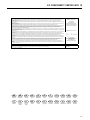
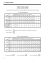
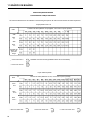
11 TORQUE CHART
22
INFORMAÇÕES GERAIS
!
AVISO
• As informações e instruções neste manual
IMPORTANTE!
ESTE MANUAL VAI AJUDÁ-LO A TRABALHAR COM
SEGURANÇA E MANTER O SEU EQUIPAMENTO
CORRECTAMENTE. LEIA TODO MANUAL ANTES
DE COMEÇAR A TRABALHAR. SE TIVER DÚVIDAS,
CONTACTE UM VENDEDOR AUTORIZADO PARA
ESCLARECIMENTO.
Para se assegurar de que está perfeitamente ciente
das informações de segurança e assistência, os dois
símbolos seguintes são utilizados ao longo deste
manual.
chamam a atenção para certas operações que
devem ser feitas com muito cuidado. Caso
contrário, pode:
• magoar-se ou magoar outras pessoas
• magoar quem trabalhar a seguir com o
equipamento
• danificar o equipamento.
• Este manual contém informações essenciais
sobre funcionamento e segurança e tem de
andar sempre com o equipamento, ao alcance
do operador.
!
Este símbolo é utilizado ao longo do manual
para chamar a sua atenção para informações sobre
actos ou situações com falta de segurança e serão
seguidas da palavra PERIGO, AVISO, ou CUIDADO.
PERIGO indica riscos imediatos que podem provocar
ferimentos graves ou morte. AVISO indica acções ou
situações arriscadas que podem provocar ferimentos
graves, morte e/ou danos materiais graves. CUIDADO
indica acções ou situações arriscadas que podem
provocar ferimentos e/ou danos materiais ligeiros.
NOTA:
Surge ao lado de informações ou instruções que
o ajudam a trabalhar e a manter correctamente o
seu equipamento.
Litho nos E.U.A. 7–2006
©2000 TEXTRON INC. • Todos os direitos reservados.
Charlotte, Carolina do Norte
O vendedor pode fornecer mais exemplares do
manual.
IMPORTANTE!
ESTE
EQUIPAMENTO
NÃO
DEVE
SER
MODIFICADO
NEM
AUMENTADO
SEM
AUTORIZAÇÃO POR ESCRITO DO FABRICANTE.
!
AVISO
• Qualquer
modificação
que
afecte
negativamente
o
funcionamento,
o
desempenho, a durabilidade ou a utilização
pode provocar condições perigosas.
Envie as suas consultas a:
Jacobsen, A Textron Company
Atenção: Engineering
11524 Wilmar Blvd
Charlotte, NC 28273 E.U.A.
INFORMAÇÕES SOBRE
ESPECIFICAÇÕES
Todas as informações contidas neste manual são as
mais recentes à data da impressão. A Textron Turf
Care and Specialty Products reserva o direito de
proceder a alterações em qualquer momento sem préaviso.
Sempre que seja especificado um produto com marca,
pode ser utilizado um produto equivalente, salvo
indicação contrária.
MUDANÇA DE PROPRIETÁRIO OU DE
ENDEREÇO
A Textron Turf Care and Specialty Products esforça-se
por manter os proprietários a par de todas as
informações sobre segurança. Assim, mudanças de
propriedade e/ou endereço devem ser comunicadas
ao fabricante.
O vendedor possui IMPRESSOS PARA MUDANÇA
DE REGISTO que são preenchidos e arquivados no
vendedor, sendo um exemplar enviado ao fabricante.
2006/42/EC: Estas instruções são as traduções das
instruções originais verificadas pela ACMTRAD SL.
ÍNDICE
Secção
N.º de página
1—— Modelos compatíveis . . . . . . . . . . . . . . . . . . . . . . . . . . . . . . . . . . . . . 2
2—— Identificação . . . . . . . . . . . . . . . . . . . . . . . . . . . . . . . . . . . . . . . . . . . . 2
3—— Material e peças para assistência . . . . . . . . . . . . . . . . . . . . . . . . . . . 2
4—— Instalação . . . . . . . . . . . . . . . . . . . . . . . . . . . . . . . . . . . . . . . . . . . . . . 3
4.1—— Desembalamento. . . . . . . . . . . . . . . . . . . . . . . . . . . . . . . . . . . . . . . . 3
4.2—— Instalação da libertação do taipal traseiro . . . . . . . . . . . . . . . . . . . . . 3
4.3—— Instalação do conjunto do elevador
Para Trucksters fabricados até Julho de 1998 . . . . . . . . . . . . . . . . . 4
4.4—— Instalação do conjunto do elevador
Para Trucksters fabricados a partir de Agosto de 1998 . . . . . . . . . . 4
4.5—— Instalar bocais dos tubos . . . . . . . . . . . . . . . . . . . . . . . . . . . . . . . . . . 7
4.6—— Instalar o conjunto do rodízio (haste) . . . . . . . . . . . . . . . . . . . . . . . . 8
4.7—— Instalar o amortecedor pneumático . . . . . . . . . . . . . . . . . . . . . . . . . . 8
4.8—— Instalar a ligação inferior e as molas de tensão superiores. . . . . . . . 9
4.9—— Instalar o manípulo de elevação . . . . . . . . . . . . . . . . . . . . . . . . . . . 10
4.10—— Montagem do transportador . . . . . . . . . . . . . . . . . . . . . . . . . . . . . . 11
4.11—— Encaminhamento das mangueiras hidráulicas . . . . . . . . . . . . . . . . 13
4.12—— Conjunto da maxila . . . . . . . . . . . . . . . . . . . . . . . . . . . . . . . . . . . . . 14
4.13—— Instalação do juntador de charutos de relva . . . . . . . . . . . . . . . . . . 15
5—— Sistema hidráulico . . . . . . . . . . . . . . . . . . . . . . . . . . . . . . . . . . . . . . 16
6—— Ajustes. . . . . . . . . . . . . . . . . . . . . . . . . . . . . . . . . . . . . . . . . . . . . . . . 16
6.1——
6.2——
6.3——
6.4——
Calibragem do veículo . . . . . . . . . . . . . . . . . . . . . . . . . . . . . . . . . . .
Plataformas de extensão . . . . . . . . . . . . . . . . . . . . . . . . . . . . . . . . .
Ajuste da correia do transportador . . . . . . . . . . . . . . . . . . . . . . . . .
Ajuste da mola de tensão . . . . . . . . . . . . . . . . . . . . . . . . . . . . . . . .
16
16
16
17
7—— Funcionamento . . . . . . . . . . . . . . . . . . . . . . . . . . . . . . . . . . . . . . . . . 17
8—— Manutenção. . . . . . . . . . . . . . . . . . . . . . . . . . . . . . . . . . . . . . . . . . . . 18
8.1——
8.2——
8.3——
8.4——
Óleo do reservatório hidráulico . . . . . . . . . . . . . . . . . . . . . . . . . . . .
Lubrificação . . . . . . . . . . . . . . . . . . . . . . . . . . . . . . . . . . . . . . . . . . .
Ajuste da corrente do elevador . . . . . . . . . . . . . . . . . . . . . . . . . . . .
Ajuste da correia do transportador . . . . . . . . . . . . . . . . . . . . . . . . .
18
18
18
18
9—— Desligar o colector de charutos de relva . . . . . . . . . . . . . . . . . . . . 19
10—— Declaração de incorporação . . . . . . . . . . . . . . . . . . . . . . . . . . . . . . . 20
11—— Gráfico de binário . . . . . . . . . . . . . . . . . . . . . . . . . . . . . . . . . . . . . . . 22
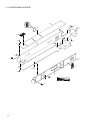
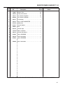
12—— Secção de peças. . . . . . . . . . . . . . . . . . . . . . . . . . . . . . . . . . . . . . . . 24
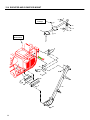
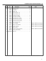
12.1—— Cabine e painéis do elevador . . . . . . . . . . . . . . . . . . . . . . . . . . . . .
12.2—— Corrente, batentes e rodas dentadas . . . . . . . . . . . . . . . . . . . . . . .
12.3—— Sistema hidráulico . . . . . . . . . . . . . . . . . . . . . . . . . . . . . . . . . . . . . .
12.4—— Montagem do transportador e elevador. . . . . . . . . . . . . . . . . . . . . .
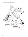
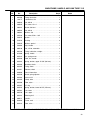
12.5—— Estrutura principal, manípulo e tubo de ligação. . . . . . . . . . . . . . . .
12.6—— Tubo de impulso, maxila e lâmina do juntador . . . . . . . . . . . . . . . .
12.7—— Extensões do transportador e da caixa . . . . . . . . . . . . . . . . . . . . . .
12.8—— Pneu, eixo e pivot do rodízio . . . . . . . . . . . . . . . . . . . . . . . . . . . . . .
24
26
28
30
32
34
36
38
1
1 MODELOS COMPATÍVEIS
1
MODELOS COMPATÍVEIS ________
O colector de charutos de relva, Peça n.º 4119652,
pode ser utilizado com os Turf Trucksters modelos
84043, 84044, 84056, 84057, 84061, 898530, 898532,
898543, 898627, 898628, 898630, 898632, 898633,
898634, 898636, 898637, 898650, 898652, 898659,
898662, 898663, 898664, 898684, 898685, 898656,
898657, & 898658. Consulte as informações abaixo
para saber se o Turf Truckster necessita de um kit de
conversão.
2
IDENTIFICAÇÃO ________________
O número de peça e o número de acessório estão
impressos no autocolante da placa de identificação
localizado na estrutura principal (Fig. 1).
O número de peça e o número de série DEVEM estar
indicados em toda a correspondência relativa a este
acessório.
AUTOCOLANTE DA PLACA
DE IDENTIFICAÇÃO
Instalação nos Cushman Turf Trucksters modelos
898530, 898532, 898543, 898630 e 898632 com pneu
traseiro de pequenas dimensões. NÃO instale o
colector de charutos de relva em modelos com um
pneu de pequenas dimensões que estejam equipados
com uma capota ou um ROPs (Peça n.º 892689).
Kits de conversão:
• 891252 Kit da haste . . . . . . . . . . . . . . . Necessário
• 887933 Conjunto da transmissão auxiliar
. . . . . . . . . . . . . . . . . . . . . . . . . . . Necessário para as
. . . . . . . . . . . . . . . . . . . . .unidades 8610 e anteriores
• 888453 Kit de actualização hidráulica . Necessário
• . . . . . . . . . . . . . . . . . . . . . . . . . . .para as unidades
8910 e anteriores
• 889558 Kit do acoplador remoto . Necessário para
• . . . . . . . . . . . . . . . . . . . . . . . . . . . . . . .as unidades
9010 e anteriores
Instalação nos Turf Trucksters modelos 898530,
898532, 898630, 898632, 898633, 898634, 898636, e
898637 mais antigos com pneu traseiro largo (23 x 1310). NÃO instale o colector de charutos de relva em
modelos com um pneu largo que estejam equipados
com uma capota ou um ROPs (Peça n.º 892689).
•
Não são necessários kits de conversão.
Instalação nos Turf Trucksters modelos 898650,
898652, 898659, 898662, 898663, 898664, 898684,
898685, 898656, 898657 e 898658 mais recentes com
pneus largos (23 x 13-10). O colector de charutos de
relva PODE SER instalados em qualquer destes
modelos que se encontre equipado com um ROPs
superior (Peça n.º 894761).
•
Não são necessários kits de conversão.
2
Figura 1
3
MATERIAL
E
PEÇAS
PARA
ASSISTÊNCIA___________________
Descrição ......................................... Número de peça
Batente, corrente do elevador........................... 832334
Acoplador, corrente........................................... 832421
Ligação, corrente .............................................. 832422
Ligação, acessório ............................................ 832423
Óleo hidráulico Turf Protector™
9,7 l (2,5 gal.) ...................................................... 65363
18,9 l (5 gal.) ....................................................... 65352
208 l (55 gal.) ...................................................... 65354
INSTALAÇÃO 4
4
INSTALAÇÃO __________________
4.1
DESEMBALAMENTO _____________________
1. Retire a fita utilizada para fixar o elevador e peças
soltas à palete. Retire da palete de transporte todas
as peças soltas e caixas, excepto o conjunto do
elevador. Retire as fitas que fixam o conjunto do tubo
de impulso ao elevador (Fig. 2).
!
CUIDADO
Mantenha as mãos e dedos afastados dos pontos
de aperto. Como estas peças se movem, podem
surgir lesões nas mãos e/ou dedos ao fazer subir
ou girar o conjunto do elevador.
2. Desloque o conjunto do tubo de impulso até à parte
frontal do elevador e permita que o tubo de impulso
fique assente no chão. Faça girar o elevador 180° de
modo a que o amortecedor e o veio pivot principal
fiquem na parte inferior (o amortecedor, a estrutura
principal e o veio pivot principal irão mover-se a
menos que estejam fixos ao elevador, pelo que pode
aplicar fitas ou cintas nestes itens para que não se
desloquem à medida que o elevador gira ou é
elevado) (Fig. 3).
3. Retire o painel do lado esquerdo do veículo.
4. Retire o retentor de anca esquerdo em Trucksters
fabricados até Julho de 1998.
IMPORTANTE!
SE O SEU VEÍCULO ESTIVER EQUIPADO COM UM
CONJUNTO DE CAIXA CURTA E UM CONJUNTO DE
LIBERTAÇÃO DO TAIPAL TRASEIRO, PEÇA N.º
885488, A LIBERTAÇÃO DO TAIPAL TRASEIRO DEVE
SER REMOVIDA. SERÁ DESLOCADA PARA O LADO
DIREITO DA CAIXA CURTA. REGISTE A POSIÇÃO E
GUARDE TODAS AS PEÇAS DURANTE A REMOÇÃO.
4.2
INSTALAÇÃO DA LIBERTAÇÃO DO TAIPAL
TRASEIRO
1. Assinale a localização conforme apresentado, parte
inferior do painel lateral da caixa do lado direito (Fig.
4). Perfure um orifício com o diâmetro de 9 mm (11/
32”) através da caixa. O suporte estará localizado
conforme o suporte no lado esquerdo. Fixe com um
parafuso 5/16-18 x 5/8 (Peça n.º 306555) e uma
porca de flange (Peça n.º 548911).
REF. SUPORTE 823038
ELEVE E DESLOQUE O
TUBO DE IMPULSO E
DEIXE-O ASSENTAR NO CHÃO
REF. PARTE
INFERIOR DA CAIXA
REF. LADO DIREITO
DO ENCOSTO DA
CAIXA FRONTAL
TUBO DE IMPULSO
Figura 2
EXIBIDO APENAS
COMO REFERÊNCIA
RODE O ELEVADOR 180°
O ELEVADOR É ENVIADO
AO CONTRÁRIO, RODE
O ELEVADOR PARA
INSTALÁ-LO
CORRECTAMENTE
NO VEÍCULO
Figura 3
NOTA:
Qualquer referência ao lado frontal, posterior,
esquerdo ou direito do veículo tem sempre como
referência a posição do operador quando está
sentado.
Figura 4
2. Introduza o conjunto da placa no encosto da caixa
frontal do lado direito. Fixe com as peças existentes.
Perfure orifícios se necessário.
3. Instale o apoio do manípulo/pivot aos orifícios
superiores existentes no encosto utilizando peças
existentes.
4. Retire a libertação do taipal traseiro existente na
parte posterior do lado direito da caixa curta. Instale
a nova lingueta de libertação do taipal traseiro (Peça
n.º 830950). Utilize as peças existentes.
5. Introduza o tirante de libertação do taipal traseiro
através do suporte na caixa. Instale o casquilho, a
anilha, a mola e a anilha no tirante e introduza
através do encosto da caixa e do pivot do manípulo.
6. Monte o tirante do taipal traseiro na nova lingueta
com uma anilha plana e um novo contrapino (Peça
n.º 306328).
7. Pressione as anilhas planas frontais contra a mola e
introduza o novo contrapino (Peça n.º 306328)
através do tirante.
3
4 INSTALAÇÃO
4.3
INSTALAÇÃO DO CONJUNTO DO ELEVADOR
PARA TRUCKSTERS FABRICADOS ATÉ
JULHO DE 1998 _________________________
!
AVISO
O conjunto do elevador é pesado e são
necessárias duas ou mais pessoas para levantá-lo.
Utilize técnicas de elevação adequadas para evitar
lesões.
1
2
Se for utilizado um guincho para elevar a unidade,
mantenha os pés e pernas afastados da parte
inferior do elevador enquanto está a ser elevado.
NOTA:
Certifique-se de que o tubo de impulso está
direccionado para a frente.
Desaperte as peças que fixam a caixa hidráulica no
batente para obter acesso às peças de montagem
da estrutura principal.
1. Coloque o suporte de montagem superior da
estrutura principal na respectiva posição contra a
PARTE FRONTAL do batente do veículo. Em
simultâneo, coloque o suporte de montagem inferior
na respectiva posição na LONGARINA do veículo.
Utilize dois parafusos, 5/16-18 x 1 (Peça n.º 306416),
quatro anilhas planas, duas anilhas de bloqueio e
porcas para fixar o suporte de montagem superior ao
batente (Fig. 5). Aperte as peças da caixa hidráulica.
2. Eleve e apoie a extremidade inferior do elevador o
suficiente para que o suporte de montagem inferior
possa ser fixo em relação à longarina do veículo,
com a flange superior do suporte para baixo contra a
parte superior da longarina. Fixe no respectivo sítio.
Utilize os orifícios do suporte como modelo. Perfure
quatro (4) orifícios de 10 mm (13/32”) através da
longarina (Fig. 6). Fixe com quatro parafusos, 3/8-16
x 1 (Peça n.º 306414), anilhas de bloqueio e porcas.
Retire as braçadeiras e apoie na extremidade inferior
do elevador.
4134
Figura 6
1. Suporte de montagem inferior
2. Longarina do veículo
4.4
INSTALAÇÃO DO CONJUNTO DO ELEVADOR
PARA TRUCKSTERS FABRICADOS A PARTIR
DE AGOSTO DE 1998
1. Instale o suporte de montagem preto (Peça n.º
894698) nos orifícios existente na estrutura do
veículo conforme apresentado na Figura 1. Fixe
utilizando dois (2) parafusos M10-1.50 x 30 (Peça n.º
452400) e duas (2) porcas M10-1.50 (Peça n.º
450454) (Fig. 7 e 8).
PEÇA N.º 450454
SUPORTE DE MONTAGEM
PEÇA N.º 894698
PEÇA N.º
452400
Figura 7
1
2
4133
SUPORTE DE MONTAGEM
Figura 5
1. Batente
2. Suporte de montagem superior da estrutura
principal
4
Figura 8
INSTALAÇÃO 4
2. Instale o suporte verde (montagem entre a
estrutura e o ROPS, Peça n.º 844797) no suporte
da montagem conforme apresentado na Figura 3.
Fixe utilizando dois (2) parafusos M10-1.50 x 30
(Peça n.º 452400). Não aperte, é necessário que
as peças permaneçam soltas para ajustar quando
o elevador estiver instalado (Fig. 9 e 10).
3. Instale o suporte de fixação (Peça n.º 844798) e a
placa de fixação (Peça n.º 844668) na estrutura do
ROPS imediatamente à esquerda do apoio para
as mãos no lado esquerdo do veículo (Fig. 11 e
12).
MONTAGEM ENTRE
A ESTRUTURA E O ROPS
Figura 10
4.
Fixe dois (2) parafusos M8-1.25 x 25 (Peça
n.º 452389) e porcas de flange M8-1.25 (Peça n.º
450453). Não aperte, pois também serão
apertados quando o elevador for montado (Fig. 11
e 12).
PEÇA N.º
450453
PLACA DE FIXAÇÃO
PEÇA N.º 844798
PLACA DE FIXAÇÃO
PEÇA N.º 844668
PEÇA N.º
452389
MONTAGEM ENTRE A
ESTRUTURA E O ROPS
PEÇA N.º 844797
PEÇA N.º
452400
Figura 11
O ELEVADOR
SERÁ MONTADO
NESTES DOIS (2)
ORIFÍCIOS
Figura 9
Figura 12
5
4 INSTALAÇÃO
!
AVISO
O conjunto do elevador é pesado e são
necessárias duas ou mais pessoas para levantálo. Utilize técnicas de elevação adequadas para
evitar lesões.
Se for utilizado um guincho para elevar a
unidade, mantenha os pés e pernas afastados
da parte inferior do elevador enquanto está a ser
elevado.
MONTAGEM ENTRE
A ESTRUTURA E O ROPS
SUPORTE DE MONTAGEM
INFERIOR DO ELEVADOR
Figura 13
5. Posicione o elevador de modo a que o suporte de
montagem inferior do elevador assente na
montagem entre a estrutura e o ROPS (Fig 13).
6. Incline o elevador para trás até o suporte de
montagem superior estar contra a parte superior
da placa de fixação (Fig. 14).
7. Fixe o elevador à montagem inferior utilizando
quatro (4) parafusos M10-1.50 x 70 (Peça n.º
452404). Não aperte.
8. Se necessário, coloque calços (ou equivalente)
sob o elevador para apoiá-lo enquanto é montado.
9. Fixe o suporte de montagem do elevador superior
à placa de fixação utilizando dois (2) parafusos
M8-1.25 x 25 (Peça n.º 452389) e porcas de flange
(Peça n.º 450453). Comece a apertar as peças
como se indica:
10. Aperte os dois parafusos que fixam a placa de
fixação e o suporte à parte superior do ROPS e,
em seguida, aperte as peças que fixam o elevador
à placa de fixação.
11. Depois aperte as peças que fixam a montagem
inferior do elevador à montagem entre a estrutura
e o ROPS.
Figura 14
SUPORTE E
PLACA DE FIXAÇÃO
PEÇA N.º 452404
PEÇA N.º 452389
MONTAGEM ENTRE
A ESTRUTURA E O ROPS
A ESTRUTURA PRINCIPAL
DO COLECTOR DE
CHARUTOS DE RELVA É
APRESENTADA SEM O
ELEVADOR APENAS
COMO REFERÊNCIA
PEÇA N.º 452404
12. Em seguida, aperte as peças que fixam a
montagem entre a estrutura e o ROPS ao suporte
de montagem preto fixo à estrutura do veículo.
6
Figura 15
INSTALAÇÃO 4
4.5
INSTALAR BOCAIS DOS TUBOS _________
TUBO DE IMPULSO
NOTA:
As imagens apresentadas nas seguintes
figuras são apresentadas apenas como
referência. Embora apresentem áreas do
colector de charutos de relva já montadas,
siga as instruções conforme descrito e
referenciado em cada passo.
É NECESSÁRIO MANTER O TUBO
DE IMPULSO SUFICIENTEMENTE
ELEVADO PARA EXIBIR OS
ORIFÍCIOS ROSCADOS
BOCAL DO TUBO
1. Eleve o tubo de impulso de forma suficiente para
exibir os dois orifícios roscados em cada lado da
parte inferior do elevador (Fig. 16).
2. Instale um bocal do tubo (Peça n.º 832430) do kit
de acessórios em cada um dos lados do elevador
e aperte (pode aplicar uma ligeira camada de
massa lubrificante nas roscas do bocal do tubo
antes da sua instalação; aperte utilizando uma
chave tubular ajustável).
Figura 16
BOCAL DO TUBO
TUBO DE IMPULSO
3. Faça descer o tubo de impulso de modo a que
assente sobre os bocais dos tubos (Fig. 17).
Figura 17
4. O tubo de impulso e o conjunto do pivot do rodízio
estão fixos ao conjunto do pino do pivot principal
(Fig. 18). O pino já se encontra introduzido através
das montagens do conjunto do pivot do rodízio e
do tubo de impulso, mas é enviado sem a anilha e
o contrapino instalados.
5. Pressione o pino do pivot a partir da parte lateral
do veículo, exteriormente através de todos os
casquilhos que fixam o conjunto do pivot do
rodízio e tubo de impulso ao pino do pivot
principal. Fixe utilizando uma (1) anilha de
grandes dimensões (Peça n.º 832479) e um
contrapino (Peça n.º 325109).
CONJUNTO DO PIVOT
DO RODÍZIO
FIXE A EXTREMIDADE
DO PINO DO PIVOT
COM A ANILHA E
O CONTRAPINO
PINO DO PIVOT
PRINCIPAL
Figura 18
7
4 INSTALAÇÃO
4.5
INSTALAR O CONJUNTO DO RODÍZIO
(HASTE) ______________________________
CONJUNTO DO
PIVOT DO RODÍZIO
1. Localize o conjunto do rodízio (haste) (Peça n.º
890118) do kit de acessórios. Direccione a
abertura das ranhuras na parte inferior da haste
para a parte frontal do veículo e introduza a haste
no tubo de montagem na extremidade do conjunto
do pivot do rodízio (Fig. 19). Fixe utilizando um (1)
anel de bloqueio (Peça n.º 548349). Faça descer
cuidadosamente o conjunto da haste e do rodízio
permitindo que a haste fique assente no chão.
2. Monte o pneu e a jante no conjunto do eixo e
cubo. O eixo e o cubo serão instalados a partir
parte lateral da jante no lado oposto à haste
válvula (Fig. 20). Introduza as cavilhas
montagem da roda através dos orifícios
montagem e fixe utilizando quatro (4) porcas
retenção da roda (Peça n.º 805860).
do
da
da
de
de
de
3. Aperte as porcas de retenção da roda entre 95 e
140 N×m (70-100 pés lbs.).
4. Instale a roda e o eixo no conjunto da haste do
rodízio fazendo deslizar o eixo contra o lado
posterior da ranhura. Certifique-se de que as
peças no eixo estão suficientemente soltas para
permitir que a estrutura da haste seja montada
entre as suas anilhas de grandes dimensões em
cada lado da haste (Fig. 21) ou retire a porca, a
anilha de bloqueio e uma anilha de grandes
dimensões de cada extremidade do eixo, faça
deslizar a roda certificando-se de que mantém
uma (1) anilha de grandes dimensões no interior
da estrutura da haste e uma anilha de grandes
dimensões no exterior da estrutura da haste. Volte
a colocar as peças.
CONJUNTO DA
HASTE DO
RODÍZIO
INTRODUZA A HASTE
ATRAVÉS DO TUBO
DO PIVOT DO RODÍZIO
Figura 19
CONJUNTO DO
CUBO E DO EIXO
PORCA DE
RETENÇÃO
DA RODA
INSTALE UM LADO DA JANTE
NO LADO OPOSTO À HASTE
PARTE FRONTAL DA
VÁLVULA VEÍCULO
HASTE DA
VÁLVULA
Figura 20
CERTIFIQUE-SE DE QUE TAMBÉM EXISTE
UMA ANILHA DE GRANDES DIMENSÕES
NO INTERIOR E EXTERIOR DA
ESTRUTURA DA HASTE NO LADO OPOSTO
ANILHA DE GRANDES
DIMENSÕES NO INTERIOR
DA ESTRUTURA DA HASTE
CONJUNTO
DA HASTE
DO RODÍZIO
ANILHA DE GRANDES
DIMENSÕES NO
EXTERIOR DA
ESTRUTURA DA HASTE
5. Aperte as porcas de retenção do eixo entre 95 e
140 N×m (70-100 pés lbs.).
4.6
INSTALAR O AMORTECEDOR PNEUMÁTICO
1. Utilizando as peças fornecidas, fixe a extremidade
inferior do amortecedor à cavilha do conjunto do
pivot do rodízio (consulte a ilustração das peças
na página 30).
2. Utilizando as peças fornecidas, fixe a extremidade
superior do amortecedor à cavilha do conjunto da
estrutura principal (consulte a ilustração das peças
na página 30).
8
FAÇA DESLIZAR O EIXO CONTRA
A PARTE POSTERIOR DA RANHURA
Figura 21
INSTALAÇÃO 4
4.7
INSTALAR A LIGAÇÃO INFERIOR E AS
MOLAS DE TENSÃO SUPERIORES _______
1.
Eleve e apoie a extremidade inferior do elevador.
Localize a mola da ligação inferior de 270 mm (10
5/8”) (Peça n.º 832525) do kit de acessórios.
Ligue uma extremidade da mola ao suporte na
ligação inferior conforme apresentado na Figura
22 (a ligação inferior está localizada em direcção
à parte frontal inferior do elevador perto do piso
do veículo conforme apresentado na Figura 23).
FAÇA DESCER A
MOLA DA LIGAÇÃO
(270 mm DE
COMPRIMENTO)
LIGUE AO SUPORTE
NA LIGAÇÃO
INFERIOR
FAÇA DESCER A MOLA DA
LIGAÇÃO (270 mm DE COMPRIMENTO)
PARAFUSO
DE AJUSTE
PORCA EM CADA
LADO DO
SUPORTE
SOBRE A
PARTE CENTRAL
PARTE FRONTAL
DO VEÍCULO
LIGAÇÃO INFERIOR
Figura 24
MOLA DE TENSÃO
SUPERIOR
PARTE FRONTAL
DO VEÍCULO
CONFORME VISTO A PARTIR
DO LADO DO PASSAGEIRO DO VEÍCULO
BARRA DE MONTAGEM
DA MOLA NA
LIGAÇÃO SUPERIOR
Figura 22
O SUPORTE NA LIGAÇÃO INFERIOR ESTÁ
LOCALIZADO NO LADO DO ELEVADOR
VIRADO PARA O VEÍCULO
A MOLA DA LIGAÇÃO INFERIOR É
APRESENTADA INSTALADA PARA
INDICAR A SUA LOCALIZAÇÃO
Figura 23
2. Ligue a outra extremidade da mola ao parafuso de
ajuste no suporte sobre a parte central (Fig. 24).
Figura 25
5. Ligue a outra extremidade da mola ao parafuso de
ajuste no suporte sobre a parte central conforme
apresentado na Figura 26. Retire o parafuso (Peça
n.º 832438) e duas (2) porcas 3/8-16 (Peça n.º
304632) do kit de acessórios e instale-os no
suporte sobre a parte central. Certifique-se de que
mantém uma porca em cada lado do suporte. A
mola será ajustada mais tarde.
PARAFUSO
DE AJSUTE
MOLA DE TENSÃO
SUPERIOR (391 mm
DE COMPRIMENTO)
3. Utilizando o parafuso (Peça n.º 832438) e duas (2)
porcas 3/8-16 (Peça n.º 304632) do kit de
acessórios, instale-os no suporte sobre a parte
central. Certifique-se de que mantém uma porca
em cada lado do suporte. A mola será ajustada
mais tarde.
4. Ligue uma extremidade da mola de tensão
superior com 391 mm (15 3/8”) de comprimento
(Peça n.º 832322) à barra de montagem na
ligação superior (Fig. 25).
PARTE FRONTAL
DO VEÍCULO
PORCA EM CADA LADO DO
SUPORTE SOBRE A PARTE CENTRAL
Figura 26
9
4 INSTALAÇÃO
4.8
INSTALAR O MANÍPULO DE ELEVAÇÃO __
1. O manípulo de elevação será montado no veio
directamente à frente do suporte sobre a parte
central (o suporte sobre a parte central é o mesmo
suporte no qual os dois parafusos de ajuste e
molas estavam previamente instalados).
2. Localize o manípulo de elevação (Peça n.º
888271) e a mola do manípulo de pequenas
dimensões (Peça n.º 812368) do kit de acessórios.
3. Aplique uma pequena quantidade de um
lubrificante à base de lítio no veio de montagem do
manípulo de elevação e faça deslizar o manípulo
no veio. O suporte soldado na parte inferior do
manípulo irá ficar virado para a parte frontal do
veículo (Fig. 27).
4. Fixe o manípulo de elevação utilizando uma (1)
anilha de retenção (Peça n.º 548165) e um (1)
contrapino (Peça n.º 304635).
MANÍPULO
DE ELEVAÇÃO
FIXE
A MOLA
SUPORTE SOBRE
A PARTE CENTRAL
Figura 27
MANÍPULO
DE ELEVAÇÃO
5. Fixe uma extremidade da mola do manípulo à aba
de montagem na parte inferior do manípulo e fixe
a outra extremidade da mola ao orifício no suporte
sobre a parte central (Fig. 27 e 28).
Figura 28
10
FAÇA DESLIZAR
O MANÍPULO
EM DIRECÇÃO
AO VEIO
INSTALAÇÃO 4
4.9
MONTAGEM DO TRANSPORTADOR ______
1. Localize o transportador, a montagem do
transportador (Peça n.º 894845) e o suporte de
encaixe (Peça n.º 888274) do kit de acessórios.
2. Coloque o suporte de encaixe no apoio de encaixe
na parte posterior do lado esquerdo da caixa (Fig.
29). Se o veículo estiver equipado com uma
caixa que não a caixa curta, o suporte de
encaixe será instalado no apoio de encaixe
central (o apoio de encaixe estará na realidade
mais próximo da parte posterior do que da parte
central da caixa).
3. Fixe o suporte de encaixe à caixa lateral utilizando
um (1) parafuso 3/8-16 x 2 1/2” (Peça n.º 301431),
uma (1) anilha plana 3/8 (Peça n.º 306981), uma
(1) anilha de bloqueio 3/8 (Peça n.º 120177) e uma
(1) porca 3/8-16 (Peça n.º 306562).
4. Instale a montagem do transportador (Peça n.º
894845) colocando o tubo com extremidade curta
90_ no apoio de encaixe frontal no lado esquerdo
da caixa e posicionando o tubo horizontal na haste
no suporte de encaixe conforme apresentado na
Figura 30.
5. Fixe o lado frontal da montagem do transportador
à caixa lateral utilizando um (1) parafuso 3/8-16 x
2 1/2” (Peça n.º 301431), uma (1) anilha plana 3/8
(Peça n.º 306981), uma (1) anilha de bloqueio 3/8
(Peça n.º 120177) e uma (1) porca 3/8-16 (Peça
n.º 306562).
6. Fixe o lado posterior da montagem do
transportador à haste no suporte de encaixe
previamente instalado (Fig. 31). Introduza um (1)
parafuso 3/8-16 x 2 3/4” (Peça n.º 307776) através
dos orifícios na haste e fixe utilizando uma (1)
anilha plana 3/8 (Peça n.º 306981), uma (1) anilha
de bloqueio 3/8 (Peça n.º 120177) e uma (1) porca
3/8-16 (Peça n.º 306562).
SUPORTE DE ENCAIXE
APOIO DE ENCAIXE
POSTERIOR ESQUERDO
(CAIXA CURTA)
APOIO DE
ENCAIXE
(CAIXA DE
GRANDES
DIMENSÕES)
Figura 29
MONTAGEM DO
TRANSPORTADOR
PEÇA N.º 894845
COLOQUE A
EXTREMIDADE
DE MONTAGEM
NA HASTE
PARA O APOIO DE
ENCAIXE FRONTAL
ESQUERDO
Figura 30
CAIXA CURTA APRESENTADA
A INSTALAÇÃO SERÁ IGUAL NA CAIXA
DE GRANDES DIMENSÕES, APENAS
DIFERE A LOCALIZAÇÃO DO APOIO DE ENCAIXE
Figura 31
11
4 INSTALAÇÃO
7. Monte o transportador na sua montagem.
Posicione o transportador nas placas de
montagem do transportador utilizando a ilustração
na Figura 32 como referência, dependendo da
caixa instalada no veículo.
CAIXA DE GRANDES DIMENSÕES
8. Fixe quatro (4) parafusos de flange M8-1.25 x 25
(Peça n.º 452389) e quatro (4) porcas de flange
M8-1.25 (Peça n.º 450453). Posicione o
transportador até os parafusos estarem contra o
lado posterior das ranhuras e aperte as peças.
9. Pode ser necessário ajustar a posição do
transportador quando utilizar o colector de
charutos de relva pela primeira vez. Os charutos
de relva devem cair do elevador para o centro da
correia do transportador. É comum que alguns dos
charutos de relva também caiam fora das partes
laterais da rampa, mas deve evitar que os
charutos de relva caiam de forma excessiva sobre
o transportador. Ajuste conforme necessário.
10. Para ajustar o transportador, desaperte os quatro
(4) parafusos entre o transportador e a montagem
e faça deslizar o transportador até ao local
pretendido. Aperte as peças após o transportador
estar devidamente posicionado (Fig. 33).
CAIXA CURTA
Figura 32
CINTA TRANSPORTADORA
SOPORTE PARA LA
CINTA TRANSPORTADORA
Figura 33
12
INSTALAÇÃO 4
4.10 ENCAMINHAMENTO
HIDRÁULICAS
DAS
MANGUEIRAS
NOTA:
Aplique fita de teflon para roscas de tubos em
todas as juntas de rosca no sistema hidráulico.
Não aperte excessivamente os encaixes
hidráulicos. Aperte as juntas até não
apresentarem fugas. Apertar excessivamente as
juntas pode provocar fugas e danos nos
encaixes.
Encaminhe a mangueira de modo a ficar afastada
de peças que se deslocam e/ou aquecem. Utilize
fixadores de arame para manter as mangueiras
fixas na respectiva posição.
Limpe todas as roscas dos encaixes hidráulicos
(extremidades macho e fêmea) com um pano limpo
(que não largue pêlos) antes de aplicar a fita de teflon.
1. Instale o encaixe hidráulico 90° (Peça n.º 827395)
do kit de acessórios na parte posterior do motor
do transportador. Aperte o encaixe de modo a que
o conector da mangueira fique virado para baixo e
ligeiramente virado em direcção à caixa (Fig. 34).
ENCAIXE 90º
PEÇA N.º 827395
ENCAIXE PLANO
PEÇA N.º 832396
BOCAL
PEÇA N.º 105706
ACOPLADOR DE
VEDANTE SECO
PEÇA N.º 894701
2. Instale o encaixe hidráulico plano (Peça n.º
832396) do kit de acessórios na parte inferior do
motor do transportador e aperte (Fig. 34).
3. Aplique fita de teflon nas roscas do bocal do tubo
hidráulico (Peça n.º 105706) do kit e instale o
bocal do tubo no encaixe plano previamente
instalado na parte inferior do motor.
4. Localize um (1) acoplador fêmea de vedante seco
(Peça n.º 894701) do kit. Instale o acoplador na
extremidade do bocal do tubo previamente
instalado (certifique-se de que é aplicada fita de
teflon no bocal).
5. Aplique algumas voltas de fita de teflon na
extremidade da mangueira e instale um (1)
acoplador macho hidráulico (Peça n.º 894702) do
kit. Encaminhe a mangueira em direcção ao motor
do transportador e ligue o acoplador macho ao
acoplador fêmea na parte inferior do motor (Fig.
35).
6. Aplique fita de teflon nas roscas dos encaixes 45°
(Peça n.º 521949) e instale e fixe os encaixes no
motor do elevador (Fig. 35).
Figura 34
MOTOR DO
ELEVADOR
MOTOR DO
TRANSPORTADOR
ACOPLADOR FÊMEA
PEÇA N.º 894701
ENCAIXE 45º
ACOPLADOR MACHO
PEÇA N.º 894702
Figura 35
7. Localize a mangueira hidráulica comprida de 762
mm (30”) do kit, aplique fita de teflon numa
extremidade da mangueira e instale-a no encaixe
45° localizado no motor do elevador.
8. Aplique fita de teflon na outra extremidade da
mangueira. Localize um (1) acoplador fêmea de
vedante seco (Peça n.º 894701) do kit e instale-o
na extremidade da mangueira.
13
4 INSTALAÇÃO
9. O acoplador será ligado à mangueira retirada da
acoplador hidráulico superior esquerdo na caixa
de controlo do sistema hidráulico localizada no
batente directamente atrás do banco do condutor.
10. Desligue a mangueira do acoplador superior na
caixa de controlo (Fig. 36) e fixe-a ao acoplador
previamente instalado na mangueira de 762 mm
(30”) proveniente da porta inferior do motor do
elevador.
11. Localize a mangueira comprida de 1422 mm (56”)
(Peça n.º 832398) que se encontra no kit de
acessórios. Aplique fita de teflon nas roscas de
uma extremidade da mangueira. Ligue a
mangueira ao encaixe 90° na parte posterior do
motor do transportador.
12. Aplique fita de teflon nas roscas da outra
extremidade da mangueira e instale o outro
acoplador macho de vedante seco (Peça n.º
894702) do kit na extremidade da mangueira.
13. Encaminhe a mangueira em direcção à caixa de
controlo do sistema hidráulico e ligue o acoplador
macho ao acoplador fêmea superior esquerdo na
caixa de controlo conforme ilustrado na Figura 37.
14. Utilize fixadores de arame ou equivalente para
manter as mangueiras afastadas de peças
móveis, pontos de aperto e/ou peças que possam
aquecer.
DESLIGUE A MANGUEIRA DO
ACOPLADOR SUPERIOR NA
CAIXA DE CONTROLO E
FIXE-A AO ACOPLADOR
NA MANGUEIRA DE 762 MM
4.11 CONJUNTO DA MAXILA_________________
1. Localize as duas (2) cintas da maxila (Peça n.º
832391, cinta do lado esquerdo, e Peça n.º 832392,
cinta do lado direito) e o conjunto da maxila (Peça n.º
887963) do kit de acessórios.
2. Retire a porca do orifício de montagem superior no
rolamento na parte inferior esquerda do elevador
(Fig. 38).
3. Instale a cinta do lado esquerdo da maxila no
parafuso do rolamento e fixe com as peças
retiradas previamente. NÃO aperte. Instale a cinta
do lado direito da maxila no lado oposto do
elevador utilizando o mesmo procedimento
utilizado para a cinta do lado esquerdo.
4. Instale o conjunto da maxila na parte inferior do
elevador fixando-o com quatro (4) parafusos 5/8-18
x 5/8 (Peça n.º 306555) e porcas de flange 5/8-18
(Peça n.º 548911). NÃO aperte já as peças.
5. Localize os dois (2) parafusos da carroçaria 5/1618 x 3/4 (Peça n.º 800358) e duas (2) porcas de
flange (Peça n.º 548911) do kit de acessórios.
6. Introduza o parafuso da carroçaria do lado inferior
da maxila através do orifício de montagem da cinta
da maxila conforme apresentado na Figura 39. Fixe
com as porcas de flange.
7. Aperte as peças de fixam o conjunto da maxila ao
elevador e aperte as peças que fixam as cintas da
maxila à maxila e flange do rolamento.
REMOVA A PORCA
SUPERIOR NA FLANGE
DO ROLAMENTO E
INSTALE A CINTA
FIXE AQUI
CINTA DA MAXILA
DO LADO ESQUERDO
CONJUNTO
DA MAXILA
FIXE AQUI
Figura 36
Figura 38
MOTOR DO
ELEVADOR
MANGUEIRA
DE 762 mm
MOTOR DO
TRANSPORTADOR
PARAFUSO DA
CARROÇARIA
MANGUEIRA
DE 1422 mm
Figura 37
14
Figura 39
INSTALAÇÃO 4
4.12 INSTALAÇÃO
DO
JUNTADOR
DE
CHARUTOS DE RELVA _________________
PINO DO PIVOT
NO TUBO DE IMPULSO
TUBO DE IMPULSO
1. Instale o conjunto do juntador (lâmina) no tubo de
impulso. Faça deslizar o conjunto do juntador no
pino do pivot do tubo de impulso conforme
apresentado na Figura 39. Fixe utilizando uma (1)
serpentina (Peça n.º 809265) do kit de acessórios.
2. Localize a placa de fixação da lâmina (Peça n.º
832309) do kit de acessórios. Alinhe as abas de
montagem nas extremidades das lâminas com os
orifícios exteriores localizados na placa de fixação
da lâmina (Fig. 41).
3. Faça deslizar uma (1) anilha plana (Peça n.º
306981) e um (1) casquilho (Peça n.º 521679)
num dos parafusos 3/8-16 x 1 (Peça n.º 306414).
Introduza o parafuso com anilha e casquilho (a
partir do lado superior) através dos orifícios de
montagem no lado esquerdo ou direito da placa de
fixação da lâmina. Fixe utilizando uma (1) anilha
de fixação 3/8 (Peça n.º 120177) e uma (1) porca
3/8-16 (Peça n.º 306562).
CONJUNTO DO JUNTADOR
Figura 40
TIRANTE
PEÇA N.º 844798
PLACA DE
FIXAÇÃO
DA LÂMINA
SUPORTE
DE APOIO
ABA DE
MONTAGEM
NO CONJUNTO
DA LÂMINA
PEÇA N.º 844798
4. Repita este procedimento no lado oposto da placa
de fixação da lâmina e aperte as peças.
5. Localize o tirante (Peça n.º 832310) no kit de
acessórios. Introduza a extremidade roscada do
tirante através do orifício localizado no suporte de
apoio preso ao tubo de impulso (Fig. 41).
6. Quando a secção do tirante passar através do
suporte de apoio, aperte uma (1) porca 7/16-14
(Peça n.º 304364) no tirante até a porca entrar em
contacto com a gola no tirante.
Figura 41
SERPENTINA
7. Introduza a extremidade roscada do tirante no
orifício central da placa de fixação da lâmina (Fig.
41) e fixe utilizando a outra porca 7/16-14, Peça
n.º 304364 (quando as peças estiverem fixas, o
lado inferior da segunda porca deve estar alinhado
com a extremidade do tirante).
8. Fixe o tirante ao suporte de apoio utilizando uma
(1) serpentina (Peça n.º 822529) (Fig. 42).
Figura 42
15
5 SISTEMA HIDRÁULICO
5
SISTEMA HIDRÁULICO___________
!
NOTA:
NÃO encha excessivamente o reservatório.
Aperte firmemente o conjunto do respirador e da
vareta no sítio.
6
AVISO
A fuga de óleo hidráulico sob pressão pode ter
força suficiente para penetrar na pele,
provocando lesões graves.
Após a montagem do sistema hidráulico e antes
de ligar o motor do veículo para aplicar pressão
ao sistema, certifique-se de que as ligações
estão firmemente apertadas e de que as
mangueiras e encaixes não estão danificados.
Após aplicar pressão ao sistema, utilize um
bloco de madeira ou papelão e não as mãos
para verificar se existem fugas.
Se o sistema necessitar de reparação,
certifique-se de que a pressão é libertada antes
de desligar as mangueiras.
Se sofrer lesões devido à fuga de fluido,
consulte imediatamente um médico. Podem
desenvolver-se infecções ou reacções graves
se não for administrada imediatamente
assistência médica.
9. Certifique-se de que o veículo está numa
superfície nivelada e de que o conjunto do
elevador está em baixo.
10. Ligue o motor do veículo e faça subir e descer a
caixa do veículo várias vezes.
11. Desloque para cima o manípulo da válvula
selectora para accionar os motores do sistema
hidráulico do elevador e do transportador.
12. Verifique todos os encaixes e conectores quanto a
fugas. Repare conforme necessário.
13. Faça descer a caixa do veículo, pare o motor do
veículo e verifique o nível de óleo do reservatório.
14. Adicione
fluido
hidráulico
biodegradável
Ransomes® Turf Protector™ ou equivalente até
visualizar óleo na parte ESTRIADA da vareta (Fig.
43).
AJUSTES ______________________
6.1 CALIBRAGEM DO VEÍCULO _____________
NOTA:
É necessária sempre uma pressão de ar MÍNIMA
de 55 PSI no amortecedor pneumático para evitar
que o Turf Truckster sofra danos estruturais.
Encha o amortecedor pneumático até ao nível
adequado do veículo com o operador no banco e
o colector de charutos de relva instalado. A
pressão MÁXIMA de ar é de 150 PSI (1034 kPa).
Encha o pneu do rodízio a 10-12 PSI (69 82 kPa).
6.2 PLATAFORMAS DE EXTENSÃO __________
15. Corte as plataformas de extensão de acordo com
o comprimento necessário, dependendo da caixa
utilizada. Instale as plataformas nos suportes do
compartimento de encaixe.
6.3 AJUSTE DA CORREIA DO
TRANSPORTADOR _____________________
NOTA:
Retire a protecção curva da parte frontal do
transportador. Se a protecção não for instalada
conforme recebida, deve ser instalada após a
correia ser ajustada (Fig. 44).
16. Desaperte as porcas de montagem do rolamento.
Aperte a correia do transportador apenas o
suficiente para permitir a sua rotação. Um aperto
excessivo irá aumentar o binário necessário para
fazer rodar a correia e irá diminuir a sua duração.
Após ajustar a correia, certifique-se de que se
encontra centrada na calha.
Ajuste a
centralização com a correia do transportador a
rodar lentamente. A correia irá afastar-se da
extremidade do seu rolo após ser apertada.
Aperte as porcas de montagem do rolamento.
3
2
VARETA DO
RESERVATÓRIO
HIDRÁULICO
1
PARTE
ESTRIADA
DA VARETA
3150
EXIBIDO APENAS
COMO REFERÊNCIA
Figura 43
16
Figura 44
1. Tirantes de ajuste da correia
2. Protecção
3. Ranhura de protecção
FUNCIONAMENTO 7
6.4
AJUSTE DA MOLA DE TENSÃO __________
17. O veículo deve estar nivelado e o elevador em
baixo.
18. Ajuste a mola de tensão inferior (Fig. 46)
regulando o parafuso de ajuste da mola de modo a
obter uma quantidade igual em cada lado do
suporte da estrutura conforme apresentado. Fixe
no sítio com porcas (Fig. 45).
7
FUNCIONAMENTO_______________
1. ANTES de utilizar o veículo com acessório,
coloque-o sobre uma superfície nivelada.
2. Verifique o veículo conforme visualizado a partir
da parte frontal para garantir que está nivelado.
3. Adicione ar, 55 PSI-150 PSI (379 a 1034 kPa), ao
amortecedor pneumático, conforme necessário,
para nivelar o veículo com o operador no banco.
PARAFUSO
DE AJUSTE
REF. SUPORTE
DA ESTRUTURA
!
Podem ocorrer lesões corporais quando a
pressão do amortecedor pneumático for
superior a 150 PSI (1034 kPa).
PORCA
PORCA
Figura 45
Encha o pneu do rodízio a 10-12 PSI (69-82 kPa).
NOTA:
Se não mantiver sempre o amortecedor
pneumático com uma pressão de ar MÍNIMA de
55 PSI, o Turf Truckster pode sofrer danos
estruturais.
PARAFUSOS
DE AJUSTE
MOLA DE TENSÃO
SUPERIOR
MOLA DE
TENSÃO INFERIOR
Figura 46
19. Em seguida, ajuste o parafuso de ajuste da mola
superior (Fig. 46) até serem necessárias 30 a 40
libras para elevar a extremidade inferior do elevador
com uma balança de mola (Fig. 47).
20. Eleve o conjunto do elevador utilizando o
manípulo de elevação.
O manípulo DEVE
deslocar-se "acima da parte central" através de
uma acção positiva.
VERIFIQUE A
TENSÃO AQUI
AVISO
4. Instale o juntador (conjunto da lâmina) utilizando
os orifícios de montagem CENTRAIS ao reunir
charutos de relva numa linha recta, tal como para
trás e para a frente num green ou em fairways.
Para realizar padrões circulares, utilize os orifícios
de montagem do lado DIREITO para a deslocação
para a ESQUERDA, orifícios de montagem do
lado ESQUERDO para a deslocação para a
DIREITA.
NOTA:
Retire SEMPRE o juntador (conjunto da lâmina)
quando transportar durante longas distâncias.
Em curtas distâncias, utilize o manípulo de
elevação para fazer subir o elevador para a
posição acima da parte central.
!
AVISO
A não remoção do conjunto do juntador antes
de transportar durante longas distâncias pode
fazer com que as lâminas estendidas elevadas
entrem em contacto com objectos ou
provoquem lesões em pessoas próximas.
NOTA:
O peso adicional das lâminas do juntador
aumenta a carga do amortecedor do colector de
charutos de relva e do veículo ao percorrer
terreno irregular.
Figura 47
5. Desloque para cima o manípulo remoto do
sistema hidráulico (válvula selectora) para iniciar o
elevador e a rotação do transportador. Desloque
para baixo o manípulo para fazer regressar o
sistema hidráulico às funções hidráulicas padrão.
17
8 MANUTENÇÃO
!
AVISO
LIGAÇÃO INFERIOR
Mantenha as partes do corpo afastadas da
abertura do elevador e do transportador quando
a máquina estiver em funcionamento.
Pressione SEMPRE (desloque para baixo o
manípulo) o controlo remoto do sistema
hidráulico e desligue o motor do veículo ANTES
de efectuar manutenção ou de remover
obstruções do elevador.
Uma corrente do elevador bloqueada pode
libertar-se subitamente e ferir uma pessoa que
esteja a trabalhar.
6. Ao colher charutos de relva em greens, conduza o
veículo às RPM do motor recomendadas.
Coloque a transmissão na PRIMEIRA velocidade
e a transmissão auxiliar na gama BAIXA.
NOTA:
Reduza a velocidade em terreno irregular ou
inclinado.
7. Quando for utilizado em fairways, coloque a
transmissão na SEGUNDA velocidade e a
transmissão auxiliar na gama BAIXA.
NOTA: Nunca utilize outras velocidades. O elevador
pode ficar obstruído.
ENCAIXE
ENCAIXE
ENCAIXE
BRAÇO DO
PIVOT DO RODÍZIO
Figura 48
8.3
AJUSTE DA CORRENTE DO ELEVADOR ___
NÃO
deixe que a corrente do elevador fique
excessivamente solta. Normalmente é necessário um
ajuste na roda dentada de accionamento superior
após cada 8 horas de funcionamento. Desaperte as
peças que fixam os rolamentos e efectue ajustes
iguais em cada rolamento superior (Fig. 49). Com a
tampa retirada, ajuste a corrente de modo a que
existam 3" de deflexão medidas no centro da corrente.
CERTIFIQUE-SE de que mantém o veio da roda
dentada perpendicular em relação à corrente. Volte a
apertar as peças após o ajuste.
8. Eleve o elevador para a posição acima da parte
central e pressione o controlo remoto do sistema
hidráulico para parar o elevador ao fazer curvas
após cada passagem.
9. Para um desgaste mínimo na cabine do elevador,
faça descer sempre o elevador em direcção ao
solo ao descarregar uma carga de charutos de
relva.
2
1
10. Pare SEMPRE a rotação do elevador e desligue o
motor do veículo antes de sair do banco do
operador.
8
MANUTENÇÃO _________________
3153
8.1 ÓLEO DO RESERVATÓRIO HIDRÁULICO __
Consulte a secção 5 para obter informações sobre o
procedimento
de
ABASTECIMENTO
DO
RESERVATÓRIO HIDRÁULICO E VERIFICAÇÃO DO
SISTEMA HIDRÁULICO. Utilize o fluído hidráulico
biodegradável Ransomes® Turf Protector™ ou um
óleo hidráulico equivalente.
8.2 LUBRIFICAÇÃO _______________________
Utilize massa lubrificante para aplicação com pistola
de pressão à base de lítio nos três (3) encaixes de
lubrificação a cada 20 horas de funcionamento.
Consulte o braço do pivot do rodízio e a ligação inferior
na figura 48.
18
Figura 49
1. Rolamento e peças
2. Parafusos de ajuste
8.4
AJUSTE DA CORREIA DO
TRANSPORTADOR _____________________
CONSULTE A SECÇÃO 6.3 AJUSTE DA CORREIA
DO TRANSPORTADOR PARA EFECTUAR ESTE
AJUSTE.
DESLIGAR O COLECTOR DE CHARUTOS DE RELVA 9
9
DESLIGAR
O
COLECTOR
DE
CHARUTOS DE RELVA___________
NOTA:
Limpe completamente os acopladores rápidos da
mangueira
para
evitar
a
entrada
de
contaminantes no sistema hidráulico.
DEVEM ser formados circuitos fechados no motor
do elevador, no motor do transportador e no
suporte do batente.
9.1
ACOPLADOR FÊMEA
ACOPLADOR
MACHO
CONSULTE O
AUTOCOLANTE
SUPORTE
DO BATENTE
DESLIGUE E VOLTE A LIGAR
ACOPLAMENTOS RÁPIDOS COMO SE
INDICA _______________________________
Figura 50
11. Desligue os dois acopladores rápidos no suporte
do batente (Fig. 50).
VÁLVULA DE
ELEVAÇÃO
12. Ligue o acoplador macho rápido na mangueira
proveniente do casquilho de encaixe no suporte
do batente ao acoplador rápido fêmea preso ao
suporte do batente. Isto cria um circuito fechado.
NOTA:
É EXTREMAMENTE IMPORTANTE que estas
duas mangueiras estejam ligadas no suporte do
batente. Isto irá evitar o sobreaquecimento do
sistema hidráulico, o qual provoca a falha do
sistema hidráulico se o manípulo remoto da
válvula selectora for puxado acidentalmente com
o acessório removido.
13. Desligue o acoplador macho rápido na mangueira
proveniente da parte inferior do motor do
transportador do encaixe inferior do motor do
elevador. Ligue este acoplador ao acoplador
fêmea na mangueira proveniente do encaixe
superior do motor do elevador. Isto cria um
circuito fechado no motor do elevador.
14. Ligue o acoplador macho na mangueira
proveniente da parte posterior do motor do
transportador ao acoplador na parte inferior do
motor do transportador. Isto cria um circuito
fechado no motor do transportador (Fig. 51).
CILINDRO DO
TRUCKSTER
ACESSÓRIO ACCIONADO
PELO MOTOR
VÁLVULA
SELECTORA
RESERVATÓRIO
HIDRÁULICO
BOMBA
HIDRÁULICA
PRESSÃO
SUCÇÃO
RETORNO
PRESSÃO OU RETORNO
CILINDRO
DO ACESSÓRIO
PARA ACESSÓRIO ACCIONADO PELO MOTOR E FUNCIONAMENTO
DA CAIXA DE DESCARGA DO TRUCKSTER: FICHA 1-4, 2-3, 8-9, 7-10.
PARA ACESSÓRIO ACCIONADO PELO MOTOR E CILINDRO DO
TRUCKSTER FORA DE SERVIÇO: FICHA 1-2, 3-4, 8-9, 7-10.
PARA FUNCIONAMENTO DO CILINDRO DO TRUCKSTER:
FICHA 1-4, 2-3, 7-8.
PARA FUNCIONAMENTO DO CILINDRO DO ACESSÓRIO:
FICHA 1-6, -23, 4-3, 7-8.
Figura 51
19
10 CERTIFICADO DE CONFORMIDADE DA CE
10
CERTIFICADO DE CONFORMIDADE DA CE _________________________________
DECLARATION OF INCORPORATION PROHLÁENÍ O ZALOENÍ SPOLENOSTI INKORPORERINGSERKLÆRING INCORPORATIEVERKLARING KINNITUS ÜHENDAMISE KOHTA ASENNUSTODISTUS DECLARATION DINCORPORATION EINBAUBESCHEINIGUNG BEÉPÍTÉSI NYILATKOZAT DICHIARAZIONE DI INCORPORAZIONE NOFORMANAS DEKLARCIJA PRIJUNGIMO DEKLARACIJA DIKJARAZZJONI
TA INKORPORAZZJONI DEKLARACJA ZGODNO!CI DLA PODZESPO"U DECLARAÇÃO DE INCORPORAÇÃO DECLARA#IE DE ÎNCORPORARE VYHLÁSENIE O
ZABUDOVANÍ SÚASTI IZJAVA ZA VGRADNJO DECLARACIÓN DE INCORPORACIÓN INBYGGNADSDEKLARATION
Business name and full address of the manufacturer Obchodní jméno a plná adresa výrobce Producentens firmanavn og fulde adresse Bedrijfsnaam en volledig adres van de fabrikant Tootja ärinimi ja täielik aadress Valmistajan toiminimi ja täydellinen osoite Nom commercial et adresse complète du fabricant Firmenname und vollständige Adresse des Herstellers !"#$%& #'()*+ !*'*!& A gyártó üzleti neve és teljes címe Ragione sociale e indirizzo completo del fabbricante Uz,-muma nosaukums un pilna raot/ja adrese Verslo pavadinimas ir pilnas gamintojo adresas Isem kummer1jali u indirizz s3i3 tal-fabbrikant Nazwa firmy i pe5ny adres producenta Nome da empresa e endereço completo do fabricante Denumirea comercial6 7i adresa complet6 a produc6torului Obchodný názov a úplná adresa výrobcu Naziv podjetja in polni naslov proizvajalca Nombre de la empresa y dirección completa del fabricante Tillverkarens företagsnamn och kompletta adress
Jacobsen, A Textron Company
11524 Wilmar Blvd.
Charlotte, NC 28273, USA
Description and identification of the partly completed machinery. @ G
Q XX Y Y. Popis a identifikace ZásteZn[ dokonZeného strojního za\ízení. Beskrivelse og identifikation af den delvist fremstillede maskine. Beschrijving en identificatie van de gedeeltelijk voltooide machinerie. Osaliselt komplekteeritud masina kirjeldus ja määratlus. Osittain kootun laitteiston kuvaus ja määrittely. Description et identification de la quasi-machine. Bezeichnung und Identifizierung der teilgefertigten Vorrichtung ]'$^$_& $%*#%$*`{ +!'|%({ +"&!%{. A részlegesen megépített gép leírása és meghatározása. Descrizione e identificazione della quasi-macchina Da }-ji pabeigtas iek/rtas apraksts un identifik/cija. Dalinai ubaigtos ~rangos apraymas ir identifikacija. Deskrizzjoni u identifikazzjoni tal-makkinarju li jkun lest parzjalment. Opis i oznaczenie czciowo ukoczonego urzdzenia Descriç ão e identificação do equipamento parcial Descrierea 7i identificarea echipamentului finalizat parial Opis a identifikácia podzostavy strojného zariadenia Opis in identifikacija delno dokonZanega stroja. Descripción e identificación de la maquinaria parcialmente completada. Beskrivning och identifiering av maskindelarna.
Product Code
Serial Number
Description
4119652
411965202700 - 411965203500
Core Harvester
2701650
270165002000 - 270165003000
Top Dresser 1500
2701600
270160002000 - 270160003000
Vicon Spreader
We undertake to transmit, in response to a reasoned request by the national authorities, relevant information on the partly completed machinery. This shall be by hardcopy and shall be without prejudice to the intellectual property rights of the
manufacturer of the partly completed machinery.
, Q , GQ XX Y Y. X Y XX Y Y.
Zavazujeme se na základ[ zdvodn[né ádosti ze strany národních ú\ad poskytnout p\ísluné informace o ZásteZn[ dokonZeném strojním za\ízení. Informace budou p\edány v tit[né podob[ a nepokodí práva k duevnímu vlastnictví výrobce
týkající se ZásteZn[ dokonZeného strojního za\ízení.
Som svar på en begrundet anmodning fra de nationale myndigheder forpligter vi os til at videregive oplysninger om den delvist fremstillede maskine. Dette bliver gjort i papirudgave og med forbehold for de immaterielle rettigheder, som indehaves af
producenten af den delvist fremstillede maskine.
We zijn van plan, in reactie op een redelijk verzoek van de nationale autoriteiten, relevante informatie over de gedeeltelijk voltooide machinerie te verzenden. Dit wordt gedaan in de vorm van fysieke kopieën en deze kopieën zullen onder alle
voorbehoud behoren tot de intellectuele eigendomsrechten van de fabrikant van de gedeeltelijk voltooide machinerie.
Me kohustume riigisiseste asutuste põhjendatud nõudmisel edastama asjakohast teavet osaliselt komplekteeritud masina kohta. Andmed edastatakse paberkandjal ning sellega ei tohi piirata osaliselt komplekteeritud masina tootja õigusi intellektuaalsele
omandile.
Sitoudumme toimittamaan osittain koottua laitteistoa koskevat olennaiset tiedot vastineena kansallisten viranomaisten perusteltuun pyyntöön. Tiedot toimitetaan paperitulosteena. Ne eivät rajoita valmistajan osittain koottua laitteistoa koskevia
immateriaalioikeuksia.
Nous nous engageons à fournir, en réponse à une demande rationnelle des autorités nationales, toute information appropriée concernant la quasi-machine. Ceci se fera par copie papier et sans préjuger des droits de propriété intellectuelle du fabricant
de la quasi-machine.
Wir verpflichten uns, auf eine begründete Aufforderung durch die nationalen Behörden hin, relevante Informationen über die teilgefertigte Maschine zu übersenden. Diese werden als Ausdruck übersandt und dürfen sich nicht nachteilig auf die Rechte
am geistigen Eigentum des Herstellers der teilgefertigten Maschine auswirken.
|%' '!*%', $%{ !+*+ '(|%^+{ !+*+{ ! ') $", !{ *"'!{ |+$%_%$'{ `*% _%$ !% +!'|{ +"+. !` ) $' ^' ^$!{ #"{ )^' ! '! #! !% !*'*!&
!% +!'|%({ +"&!%{.
Vállaljuk, hogy átadjuk a nemzeti hatóságok megalapozott kérésére válaszul a részlegesen megépített gépre vonatkozó információkat. Az információkat nyomtatott példányban adjuk át. A nyomtatott példány átadása a részlegesen megépített gép
gyártójának szellemi tulajdonjogaira tett kötelezettség nélkül történik.
Ci impegniamo a trasmettere, in risposta ad una richiesta adeguatamente motivata delle autorità nazionali, informazioni pertinenti sulla quasi-macchina. Limpegno sarà redatto in forma cartacea e lascerà impregiudicati i diritti di proprietà intellettuale del
fabbricante della quasi-macchina.
Atsaucoties uz pamatotu valsts iest/u pieprasjumu, m-s ap,emamies nodot saistto inform/ciju par da}-ji pabeigtu iek/rtu. T/ bs ciet/ kopija un nerads kait-jumus da}-ji pabeigt/s iek/rtas raot/ja intelektu/l/ pauma tiesb/m.
Atsakydami ~ nacionalini valdios organ uklaus, pateikiame informacij apie dalinai ubaigtus mechanizmus. is dokumentas yra atspausdintas elektroninio originalo variantas ir be jokio iankstinio nusistatymo neturi tikslo paeisti dalinai ubaigto
mechanizmo gamintojo intelektualins nuosavybs teisi.
A3na nwieg3du li nippreentaw, meta mitlubin mill-awtoritajiet nazzjonali, l-informazzjoni relevanti dwar il-makkinarju li jkun lest parzjalment. Din l-informazzjoni g3andha tkun fforma stampata u ming3ajr preudizzju g3ad-drittijiet tal-proprjetà intelletwali
tal-fabbrikant tal-makkinarju li jkun lest parzjalment.
Na uzasadnion prob instytucji pastwowych zobowizujemy si do przekazania wszelkich informacji na temat czciowo ukoczonego urzdzenia. Bd one przekazane na pimie. Strona przekazujca w/wym. dokumentacj nie bdzie roci5a sobie
adnych praw do w5asnoci intelektualnej producenta czciowo ukoczonego urzdzenia.
Na sequência de pedido razoável por parte das autoridades nacionais, comprometemo-nos a transmitir informações importantes sobre o equipamento parcial. Tal será feito por meio de hardcopy
e sem prejuízo para os direitos de propriedade intelectual do fabricante do equipamento parcial.
Ne angaj6m s6 transmitem, ca r6spuns la o solicitare motivat6 a autorit6ilor naionale, informaii relevante privind echipamentul finalizat parial. Aceasta se va efectua în format hârtie 7i f6r6 a aduce atingere drepturilor de proprietate intelectual6 ale
produc6torului echipamentului finalizat parial.
Zaväzujeme sa, e na základe odôvodnenej poiadavky národných orgánov predloíme dôleité informácie o podzostave strojného zariadenia.
Musí to by v tlaZenej forme a bez ujmy na právach duevného vlastníctva výrobcu podzostavy strojného zariadenia.
Zavezujemo se, da bomo na utemeljeno zahtevo nacionalnih organov predloili zadevne informacije o delno dokonZanem stroju. Informacije bodo v tiskani obliki in ne bodo posegale v pravice intelektualne lastnine proizvajalca delno dokonZanega stroja.
Nos comprometemos a transmitir, en respuesta a una petición razonada por parte de las autoridades nacionales, información relevante sobre la maquinaria parcialmente completada. Ésta será transmitida en copia impresa y no afectará a los derechos
de propiedad intelectual del fabricante de la maquinaria parcialmente completada.
Vi åtar oss att vidarebefordra relevant information om maskindelarna vid en motiverad förfrågan från nationella myndigheter. Informationen ska erhållas i form av papperskopior och ska vara utan men för maskindelstillverkarens immateriella rättigheter.
Partly completed machinery must not be put into service until the final machinery into which it is to be incorporated has been declared in conformity with the provisions of Directive 2006/42/EC.
X Y Y
, Y, , 2006/
42/E@.
ásteZn[ dokonZené za\ízení nesmí být uvedeno do provozu, dokud koneZné za\ízení, do kterého bylo uvedené za\ízení namontováno, neodpovídá ustanovením Sm[rnice Z. 2006/42/EC.
Delvist fremstillede maskiner må ikke indsættes i driften, før den endelige maskine, som den skal inkorporeres i, er blevet erklæret I overensstemmelse med bestemmelserne i Direktiv 2006/42/EF.
Gedeeltelijk voltooide machinerie mag niet in dienst worden genomen, totdat er voor de definitieve machinerie, waarvan gedeeltelijk voltooide machinerie onderdeel uitmaakt, een conformiteitsverklaring
is ontvangen onder de voorwaarden van Richtlijn 2006/42/EG.
Osaliselt komplekteeritud masinat ei tohi kasutusele võtta enne, kui lõplikult komplekteeritud masin, millega see ühendatakse, on tunnistatud direktiivi 2006/42/EÜ sätetele vastavaks.
Osittain koottua laitteistoa ei saa ottaa käyttöön, ennen kuin lopullinen laitteisto, johon se asennetaan, on vakuutettu direktiivin 2006/42/EY säännösten mukaiseksi.
La quasi-machine ne doit pas être mise en service avant que la machine finale dans laquelle elle doit être incorporée nait été déclarée conforme aux dispositions de la directive 2006/42/CE
Die teilgefertigte Vorrichtung darf erst in Betrieb genommen werden, wenn die Konformität der Maschine, in die sie eingebaut wird, entsprechend den Bestimmungen der Richtlinie 2006/42/EG erklärt
worden ist.
¢ $' '!'|'*!' *${ *!% +!'|{ +"+ "$ !% !'|` +"+ *!% %%% ) '*!)' "' !+ #&|*+ *`$_*+{, *(_ ' !{ #!£'{ !+{ ¤#+^{ 2006/42/¥.
A részlegesen megépített gépet tilos üzembe helyezni mindaddig, amíg a 2006/42/EK irányelv rendelkezéseivel összhangban a részlegesen megépített gépet be nem építik a végleges változatba, és
err¦l nem nyilatkoznak.
La quasi-macchina non deve essere messa in servizio finché la macchina finale in cui deve essere incorporata non è stata dichiarata conforme, nel caso, alle disposizioni della Direttiva 2006/42/CE.
Da}-ji pabeigtu iek/rtu nedrkst nodot ekspluat/cij/, ldz galg/ iek/rta, kur/ t/ ir j/iebv-, ir deklar-ta atbilstoi direktvas Nr. 2006/42/EK noteikumiem.
Dalinai ubaigto mechanizmo negalima paleisti kol kiti mechanizmai, kurie dar bus prijungti, nebus patvirtinti kaip atitinkantys 2006/42/EC Direktyvos reikalavimus.
Il-makkinarju li jkun parzjalment lest ma g 3andux jibda jit3addem sakemm il-makkinarju finali li fih ikun se ji i inkorporat ikun ie ddikjarat konformi mad-dispoizzjonijiet tad-Direttiva 2006/42/KE.
Urzdzenia czciowo ukoczonego nie wolno uytkowa§ a do orzeczenia zgodnoci urzdzenia w postaci kompletnej z wymaganiami dyrektywy 2006/42/WE.
O equipamento parcial não poderá entrar em funcionamento antes do mecanismo final no qual vai ser incorporado ser declarado como estando em conformidade com as condições da Directiva 2006/
42/CE.
Echipamentul finalizat parial nu trebuie pus în funciune pân6 ce echipamentul final în care va fi încorporat nu este declarat ca fiind conform cu prevederile Directivei 2006/42/CE.
Podzostava strojného zariadenia nesmie by uvedená do prevádzky, pokia¨ finálne strojné zariadenie, ktorého sa stane súZasou, nebude vyhlásené ako zhodné s ustanoveniami smernice 2006/42/ES.
Delno dokonZanega stroja ni dovoljeno dati v obratovanje, dokler se dokonZani stroj, v katerega se vgradi delno dokonZani stroj, ne potrdi kot skladen z doloZbami Direktive 2006/42/ES.
La maquinaria parcialmente completada no debe ponerse en servicio hasta que la maquinaria final a la que debe incorporarse cumpla con las provisiones de la Directiva 2006/42/CE.
Maskindelarna får ej tas i bruk förrän maskinen som delen tillhör har deklarerats som överensstämmande med föreskrifterna I direktivet 2006/42/EG.
The place and date of the declaration © Q Místo a datum prohláení Sted og dato for erklæringen Plaats en datum van de verklaring Deklaratsiooni väljastamise koht ja kuupäev Vakuutuksen paikka ja päivämäärä Lieu et date de la déclaration Ort und Datum der Erklärung ª`%{ +'$%+ #&|*+{ A nyilatkozat kelte (hely és id¦) Luogo e data della dichiarazione Deklar/cijas vieta un datums Deklaracijos vieta ir data Il-post u d-data tad-dikjarazzjoni Miejsce i data wystawienia deklaracji Local e data da declaração Locul 7i data declaraiei Miesto a dátum
vyhlásenia Kraj in datum izjave Lugar y fecha de la declaración Plats och datum för deklarationen
20
These accessories have been
designed to be fitted to the Cushman
Turf Truckster 84064
Jacobsen, A Textron Company
11524 Wilmar Blvd.
Charlotte, NC 28273, USA
July 19th, 2010
CERTIFICADO DE CONFORMIDADE DA CE 10
Signature of the person empowered to draw up the declaration on behalf of the manufacturer, holds the technical documentation and is authorised to compile the technical file, and who is established in
the Community.
 X
, Q , Ä ÅX
Q ÅX
G .
Podpis osoby oprávn[né sestavit prohláení jménem výrobce, dret technickou dokumentaci a osoby oprávn[né sestavit technické soubory a zaloené v rámci Evropského spoleZenství.
Underskrift af personen, der har fuldmagt til at udarbejde erklæringen på vegne af producenten, der er indehaver af dokumentationen og er bemyndiget til at udarbejde den tekniske journal, og som er
baseret i nærområdet.
Handtekening van de persoon die bevoegd is de verklaring namens de fabrikant te tekenen, de technische documentatie bewaart en bevoegd is om het technische bestand samen te stellen, en die is
gevestigd in het Woongebied.
Ühenduse registrisse kantud isiku allkiri, kes on volitatud tootja nimel deklaratsiooni koostama, kes omab tehnilist dokumentatsiooni ja kellel on õigus koostada tehniline toimik.
Sen henkilön allekirjoitus, jolla on valmistajan valtuutus vakuutuksen laadintaan, jolla on hallussaan tekniset asiakirjat, joka on valtuutettu laatimaan tekniset asiakirjat ja joka on sijoittautunut yhteisöön.
Signature de la personne habilitée à rédiger la déclaration au nom du fabricant, à détenir la documentation technique, à compiler les fichiers techniques et qui est implantée dans la Communauté.
Unterschrift der Person, die berechtigt ist, die Erklärung im Namen des Herstellers abzugeben, die die technischen Unterlagen aufbewahrt und berechtigt ist, die technischen Unterlagen
zusammenzustellen, und die in der Gemeinschaft niedergelassen ist.
Æ%^$_& !`% '£%*%#%!+% ^ !+ *(!£+ !+{ #&|*+{ ' $%{ !% !*'*!&, % %%%{ !"' !+ !'"& )'*+ "' !+ '£%*%#`!+*+ !£%&*' !% !'"` _'|% % %%%{ ' #%$*%{ *!+ ¥%`!+!.
A gyártó nevében meghatalmazott személy, akinek jogában áll módosítania a nyilatkozatot, a mÈszaki dokumentációt ¦rzi, engedéllyel rendelkezik a mÈszaki fájl összeállításához, és aki a közösségben
letelepedett személy.
Firma della persona autorizzata a redigere la dichiarazione a nome del fabbricante, in possesso Della documentazione tecnica ed autorizzata a costituire il fascicolo tecnico, che deve essere stabilita
nella Comunità.
T/s personas paraksts, kura ir pilnvarota deklar/cijas sast/danai raot/ja v/rd/, kurai ir tehnisk/ dokument/cija, kura ir pilnvarota sagatavot tehnisko reÊistru un kura ir apstiprin/ta Kopien/.
Asmuo, kuris yra gana inomas, kuriam gamintojas suteik ~galiojimus sudaryti i deklaracij, ir kuris j pasira, turi vis technin informacij ir yra ~galiotas sudaryti technins informacijos dokument.
Il-firma tal-persuna awtorizzata li tfassal id-dikjarazzjoni fisem il-fabbrikant, g3andha d-dokumentazzjoni teknika u hija awtorizzata li tikkompila l-fajl tekniku u li hija stabbilita fil-Komunità.
Podpis osoby upowanionej do sporzdzenia deklaracji w imieniu producenta, przechowujcej dokumentacj techniczn, upowanion do stworzenia dokumentacji technicznej oraz wyznaczonej ds.
wspólnotowych.
Assinatura da pessoa com poderes para emitir a declaração em nome do fabricante, que possui a documentação técnica, que está autorizada a compilar o processo técnico e que está estabelecida na
Comunidade.
Semn6tura persoanei împuternicite s6 elaboreze declaraia în numele produc6torului, care deine documentaia tehnic6, este autorizat6 s6 compileze dosarul tehnic 7i este stabilit6 în Comunitate.
Podpis osoby poverenej vystavením vyhlásenia v mene výrobcu, ktorá má technickú dokumentáciu a je oprávnená spracova technické podklady a ktorá je umiestnená v SpoloZenstve.
Podpis osebe, pooblaZene za izdelavo izjave v imenu proizvajalca, ki ima tehniZno dokumentacijo in lahko sestavlja spis tehniZne dokumentacije, ter ima sede v Skupnosti.
Firma de la persona responsable de la declaración en nombre del fabricante, que posee la documentación técnica y está autorizada para recopilar el archivo técnico y que está establecido en la
Comunidad.
Undertecknas av den som bemyndigad att upprätta deklarationen å tillverkarens vägnar, innehar den tekniska dokumentationen och är bemyndigad att sammanställa den tekniska informationen och
som är etablerad i gemenskapen.
Certificate Number G
íslo osv[dZení Certifikatnummer Certificaatnummer Sertifikaadi number Hyväksyntänumero Numéro de certificat Bescheinigungsnummer $)`{ ]*!%%+!%( Hitelesítési szám Numero del certificato Sertifik/ta numurs Sertifikato numeris Numru ta1-Ëertifikat Numer certyfikatu Número do Certificado Num6r certificat íslo osvedZenia tevilka certifikata Número de certificado Certifikatsnummer
2006/42/EC Annex II 1.A.2
Tim Lansdell
Technical Director
Ransomes Jacobsen Limited
West Road, Ransomes Europark,
Ipswich, IP3 9TT, England
2006/42/EC Annex II 1.A.10
Ryan Weeks
VP of Engineering
July 19th, 2010
Jacobsen, A Textron Company
11524 Wilmar Blvd,
Charlotte, NC 28273, USA
4239003 Rev A
GB
BG
CZ
DK
NL
EE
FI
FR
DE
GR
HU
English
български
čeština
dansk
Nederlands
eesti
suomi
français
Deutsch
Ελληνικά
magyar
IT
LV
LT
MT
PL
PT
RO
SK
italiano
latviešu
valoda
lietuvių
kalba
Malki
polski
português
Română
slovenčina
SI
slovenščina
ES
SE
Ελληνικά
Svenska
21
11 GRÁFICO DE BINÁRIO
ESPECIFICAÇÕES DE BINÁRIO
PARAFUSOS DE CABEÇA SEXTAVADA
Os valores de binário devem ser utilizados como directriz geral quando não são fornecidos valores de binário específicos.
Peças padrão nos E.U.A.
Tamanho da haste (diâmetro em polegadas, rosca muito ou pouco precisa)
Grau
SAE
Grau
5*
SAE
Grau
8**
Parafuso de
flange com
porca de
flange
* Grau com marca 5 -
Qualidade comercial mínima (qualidade inferior não recomendada).
** Grau com marca 8 -
Peças métricas padrão
Tamanho da haste (diâmetro em mm, rosca muito ou pouco precisa)
Grau
Grau
8.8*
Grau
10.9**
Grau
12.9***
* Grau com marca 8.8 -
22
** Grau com marca 10.9 -
*** Grau com marca 12.9 -
5'%1&'2'#5 12
SECÇÃO
DE PEÇAS
23
12.1 ELEVATOR PANELS AND BOOT
14
2
17
3
3
5
15
1
2
2
2
4
1
9
8
3
7
12
3
13
2
e
rv
re
Co
2
Ha
er
st
11
6
3
11
7
24
ELEVATOR PANELS AND BOOT 1.1
Ref.
No.
Part
No.
Description
No.
Req’d
1
103867
Washer, 5/16 . . . . . . . . . . . . . . . . . . . . . . . . . . . . . . 34
2
306555
Screw, 5/16-18 x 5/8 . . . . . . . . . . . . . . . . . . . . . . . . 44
3
548911
Nut, 5/16-18, flangelock . . . . . . . . . . . . . . . . . . . . . 42
4
800290
Nut, 5/16-18, centerlock . . . . . . . . . . . . . . . . . . . . . . 2
5
832372
End, elevator . . . . . . . . . . . . . . . . . . . . . . . . . . . . . . . 1
6
839216
Decal, CORE HARVESTE5 . . . . . . . . . . . . . . . . . . 1
7
832430
Nipple, pipe . . . . . . . . . . . . . . . . . . . . . . . . . . . . . . . . 2
8
837261
Channel, bottom . . . . . . . . . . . . . . . . . . . . . . . . . . . . 1
9
888002
Boot . . . . . . . . . . . . . . . . . . . . . . . . . . . . . . . . . . . . . . . 1
10
890120
Channel, right . . . . . . . . . . . . . . . . . . . . . . . . . . . . . . . 1
11
4152420
Decal, Jacobsen . . . . . . . . . . . . . . . . . . . . . . . . . . . . 1
12
890129
Channel, left w/decal . . . . . . . . . . . . . . . . . . . . . . . . 1
13
840909
Decal, WARNING . . . . . . . . . . . . . . . . . . . . . . . . . . 1
14
890130
Cover, top w/decal . . . . . . . . . . . . . . . . . . . . . . . . . . 1
15
840909
Decal, WARNING . . . . . . . . . . . . . . . . . . . . . . . . . . 1
840988
Decal, Information . . . . . . . . . . . . . . . . . . . . . . . . . . . 1
Notes
16
17
• INDENTED PART NAMES INDICATE THESE PARTS ARE INCLUDED IN PRECEDING ASSEMBLY
2
1.2 CHAIN, PADDLES, AND SPROCKETS
To
Elevator
Motor
29
2
13 16
Reference Elevator
End Plate
18
10
32
15
31
12
4
1
28
35
20
23
45
12
12
7
1
1
24
12
Reference Elevator
Channel (Right Side)
11
12
20
13
31
33
30
21
39
38
32
18
25
40
41
Reference Elevator
Channel (Left Side)
14
37
6
22
3
5
6
19
26
43
8
42
22
25
27
17
21
2
FRONT
OF
VEHICLE
11
9
Reference Elevator
Channel (Left Side)
21
34
25
19
36
25
14
6
21
3
17
2
9
20
31
32
Reference Elevator
Channel (Left Side)
2
18
Reference Elevator
Channel (Left Side)
CHAIN, PADDLES, AND SPROCKETS 1.2
Ref.
No.
1
2
3
4
5
6
7
8
9
10
11
12
13
14
15
16
17
18
19
20
21
22
23
24
25
26
27
28
29
30
31
32
33
34
35
36
37
38
39
40
41
42
43
44
45
Part
No.
103867
120177
302030
306325
306375
306396
306450
306487
306562
306834
306835
306932
306981
308090
309855
548205
548804
548911
800236
800557
823025
810386
832294
832299
832300
832334
832336
832360
832361
832362
832405
832440
832940
887958
887959
887977
887978
887993
832421
832422
832423
888077
800520
832533
800300
Description
No.
Req’d
Notes
Washer, 5/16 . . . . . . . . . . . . . . . . . . . . . . . . . . . . . . . 6
Lockwasher, 3/8 . . . . . . . . . . . . . . . . . . . . . . . . . . . . 8
Screw, 1/4-20 x 1 1/4 . . . . . . . . . . . . . . . . . . . . . . . . 8
Lockwasher, 5/16 . . . . . . . . . . . . . . . . . . . . . . . . . . . 2
Nut, 1/4-20 . . . . . . . . . . . . . . . . . . . . . . . . . . . . . . . . 52
Lockwasher, 1/4 . . . . . . . . . . . . . . . . . . . . . . . . . . . 52
Screw, 5/16-18 x 3/4 . . . . . . . . . . . . . . . . . . . . . . . . . 2
Screw, 1/4-20 x 5/8 . . . . . . . . . . . . . . . . . . . . . . . . . 52
Nut, 3/8-16 . . . . . . . . . . . . . . . . . . . . . . . . . . . . . . . . . 4
Screw, 3/8-16 x 3/4 . . . . . . . . . . . . . . . . . . . . . . . . . . 4
Screw, 3/8-16 x 1 1/4 . . . . . . . . . . . . . . . . . . . . . . . . 4
Nut, 5/16-18 . . . . . . . . . . . . . . . . . . . . . . . . . . . . . . . 10
Washer, 3/8 . . . . . . . . . . . . . . . . . . . . . . . . . . . . . . . . 4
Washer, 1/4 . . . . . . . . . . . . . . . . . . . . . . . . . . . . . . . . 8
Key, woodruff, size A . . . . . . . . . . . . . . . . . . . . . . . . . 1
Screw, set, 1/4-20 x 1/4 . . . . . . . . . . . . . . . . . . . . . . 2
Nut, flangelock, 3/8-16 . . . . . . . . . . . . . . . . . . . . . . 16
Nut, flangelock, 5/16-18 . . . . . . . . . . . . . . . . . . . . . . 8
Bolt, carriage, 3/8-16 x 3/4 . . . . . . . . . . . . . . . . . . 16
Bolt, carriage, 5/16-18 x 3/4 . . . . . . . . . . . . . . . . . . 8
Cap, ball joint . . . . . . . . . . . . . . . . . . . . . . . . . . . . . . . 4
Tee nut, 1/4-20 . . . . . . . . . . . . . . . . . . . . . . . . . . . . . . 8
Coupler . . . . . . . . . . . . . . . . . . . . . . . . . . . . . . . . . . . . 1
Rod, threaded, chain adjustment . . . . . . . . . . . . . . . . 2
Bushing, ball pivots . . . . . . . . . . . . . . . . . . . . . . . . . . 4
Paddle, elevator chain . . . . . . . . . . . . . . . . . . . . . . 26
Board, support . . . . . . . . . . . . . . . . . . . . . . . . . . . . . . 1
Slide, motor . . . . . . . . . . . . . . . . . . . . . . . . . . . . . . . . 1
Mount, motor . . . . . . . . . . . . . . . . . . . . . . . . . . . . . . . 1
Slide, bearing . . . . . . . . . . . . . . . . . . . . . . . . . . . . . . . 1
Bearing, ball, flush mount . . . . . . . . . . . . . . . . . . . . 4
Collar, locking . . . . . . . . . . . . . . . . . . . . . . . . . . . . . . . 4
Cover, dust . . . . . . . . . . . . . . . . . . . . . . . . . . . . . . . . . 1
Sprocket, driven . . . . . . . . . . . . . . . . . . . . . . . . . . . . 1
Sprocket, drive . . . . . . . . . . . . . . . . . . . . . . . . . . . . . . 1
Pivot, lower mounting . . . . . . . . . . . . . . . . . . . . . . . . 1
Pivot, upper mounting . . . . . . . . . . . . . . . . . . . . . . . . 1
Chain, elevator . . . . . . . . . . . . . . . . . . . . . . . . . . . . . . 1
SCoupler, chain . . . . . . . . . . . . . . . . . . . . . . . . . . . . . 1
SLink, chain . . . . . . . . . . . . . . . . . . . . . . . . . . . . . . . . 77
SLink, attachment . . . . . . . . . . . . . . . . . . . . . . . . . . 26
Board, support . . . . . . . . . . . . . . . . . . . . . . . . . . . . . . 1
SScrew, #8 x 3/4, wood . . . . . . . . . . . . . . . . . . . . . . . 9
SStrip, wear . . . . . . . . . . . . . . . . . . . . . . . . . . . . . . . . . 1
Nut, 5/16-18, acorn . . . . . . . . . . . . . . . . . . . . . . . . . . 2
• INDENTED PART NAMES INDICATE THESE PARTS ARE INCLUDED IN PRECEDING ASSEMBLY
2
1.3 HYDRAULIC SYSTEM
10
* Seal Kit
Part No. 833237
7
11
Seal Kit
Part No. 833347
*
9
8
17
5
1
5
16
14
15
13
12
Shown as
Reference Only
4
15
6
3
2
Mounts to Bottom
Side of Elevator
14
2
HYDRAULIC SYSTEM 1.3
Ref.
No.
1
Part
No.
Description
No.
Req’d
2
105706
133836
306375
Nipple, 3/8-18 NPT . . . . . . . . . . . . . . . . . . . . . . . . . . 1
Tape, teflon . . . . . . . . . . . . . . . . . . . . . . . . . . . . . . . . . 1
Nut, 1/4-20 . . . . . . . . . . . . . . . . . . . . . . . . . . . . . . . . . 1
3
306396
Lockwasher, 1/4 . . . . . . . . . . . . . . . . . . . . . . . . . . . . 1
4
306487
Screw, 1/4-20 x 5/8 . . . . . . . . . . . . . . . . . . . . . . . . . . 1
5
521949
Adapter, 45_ . . . . . . . . . . . . . . . . . . . . . . . . . . . . . . . . 2
6
809092
Clamp . . . . . . . . . . . . . . . . . . . . . . . . . . . . . . . . . . . . . 1
7
827395
Adapter, 90_ . . . . . . . . . . . . . . . . . . . . . . . . . . . . . . . . 1
8
832396
Fitting, straight hydraulic . . . . . . . . . . . . . . . . . . . . . 1
9
832398
Hose, hydraulic, 56” (1,432 mm) . . . . . . . . . . . . . . . 1
10
832401
Motor, hydraulic (conveyor) . . . . . . . . . . . . . . . . . . . 1
11
12
553046
833237
832403
SKey, woodruff #3 . . . . . . . . . . . . . . . . . . . . . . . . . . . 1
SKit, seal . . . . . . . . . . . . . . . . . . . . . . . . . . . . . . . . . . . 1
Hose, hydraulic, 60” (1524 mm) . . . . . . . . . . . . . . . 1
13
844810
Hose, hydraulic, 30” (762 mm) . . . . . . . . . . . . . . . . 1
14
894701
Coupler, hydraulic dryseal . . . . . . . . . . . . . . . . . . . . 2
15
894702
Nipple, hydraulic dryseal . . . . . . . . . . . . . . . . . . . . . 2
16
887989
Motor, hydraulic (elevator) . . . . . . . . . . . . . . . . . . . . 1
17
309855
833347
SKey, woodruff (size A) . . . . . . . . . . . . . . . . . . . . . . . 1
SKit, seal . . . . . . . . . . . . . . . . . . . . . . . . . . . . . . . . . . . 1
Notes
Not Illustrated
Not Illustrated
Not Illustrated
• INDENTED PART NAMES INDICATE THESE PARTS ARE INCLUDED IN PRECEDING ASSEMBLY
2
1.4 ELEVATOR AND CONVEYOR MOUNT
3
2
Used to Mount
Conveyor
1
8
5
4
2
1
11
6
Shown as
Reference Only
6
14
7
12
8
18
8
13
9
16
9
17
10
3
15
ELEVATOR AND CONVEYOR MOUNT 1.4
Ref.
No.
Part
No.
Description
No.
Req’d
Notes
1
120177
Lockwasher, 3/8 . . . . . . . . . . . . . . . . . . . . . . . . . . . . 3
2
306562
Nut, 3/8-16 . . . . . . . . . . . . . . . . . . . . . . . . . . . . . . . . . 3
3
306981
Washer, 3/8 . . . . . . . . . . . . . . . . . . . . . . . . . . . . . . . . 3
4
301431
Screw, 3/8-16 x 2 1/2 . . . . . . . . . . . . . . . . . . . . . . . . 2
5
307776
Screw, 3/8-16 x 2 3/4 . . . . . . . . . . . . . . . . . . . . . . . . 1
6
450453
Nut, M8-1.25 (G10.9) . . . . . . . . . . . . . . . . . . . . . . . . 8
7
450454
Nut, M10-1.50 (G10.9) . . . . . . . . . . . . . . . . . . . . . . . 2
8
452389
Screw, M8-1.25 x 25 (8.8) . . . . . . . . . . . . . . . . . . . . 8
9
452400
Screw, M10-1.50 x 30 (8.8) . . . . . . . . . . . . . . . . . . . 4
10
452404
Screw, M10-1.50 x 70 (8.8) . . . . . . . . . . . . . . . . . . . 4
11
894845
Plate, conveyor mount . . . . . . . . . . . . . . . . . . . . . . . 1
12
844668
Plate, clamping . . . . . . . . . . . . . . . . . . . . . . . . . . . . . 1
Used on 1998 Trucks and newer.
13
844797
Mount, frame to ROPS . . . . . . . . . . . . . . . . . . . . . . . 1
Used on 1998 Trucks and newer.
14
844798
Bracket, clamping . . . . . . . . . . . . . . . . . . . . . . . . . . . 1
Used on 1998 Trucks and newer.
15
888274
Stake, bracket . . . . . . . . . . . . . . . . . . . . . . . . . . . . . . 1
16
894698
Bracket assembly, mounting . . . . . . . . . . . . . . . . . . 1
17
890116
Frame, main (elevator) . . . . . . . . . . . . . . . . . . . . . . . 1
18
009039290
Decal, CE . . . . . . . . . . . . . . . . . . . . . . . . . . . . . . . . . . 1
Used on 1998 Trucks and newer.
• INDENTED PART NAMES INDICATE THESE PARTS ARE INCLUDED IN PRECEDING ASSEMBLY
1.5 MAIN FRAME, HANDLE, AND LINK TUBE
33
6
30
2
7
9
31
5
7
2
10
10
7
31
17
16
7
8
9
5
5
23
7
3
18
10
3
15
14
3
23
11
4
32
7
2
1
28
6
21
21
12
13
20
29
25
19
26
27
27
24
SHOWN EXPLODED VIEW
FOR REFERANCE ONLY
NOT OFFERED AS A KIT
34
21
21
Reference Caster Pivot
Part No. 890117
3
22
13
MAIN FRAME, HANDLE, AND LINK TUBE 1.5
Ref.
No.
Part
No.
1
807439
Fitting, lubrication . . . . . . . . . . . . . . . . . . . . . . . . . . . . . 1
2
120177
Lockwasher, 3/8 . . . . . . . . . . . . . . . . . . . . . . . . . . . . . . 3
3
304632
Nut, 3/8-16 . . . . . . . . . . . . . . . . . . . . . . . . . . . . . . . . . . . 4
4
304635
Pin, cotter, 1/8 x 1 . . . . . . . . . . . . . . . . . . . . . . . . . . . . . 1
5
306414
Screw, 3/8-16 x 1 . . . . . . . . . . . . . . . . . . . . . . . . . . . . . 3
6
306562
Nut, 3/8-16 . . . . . . . . . . . . . . . . . . . . . . . . . . . . . . . . . . . 2
7
306981
Washer, 3/8 . . . . . . . . . . . . . . . . . . . . . . . . . . . . . . . . . . 6
8
325109
Pin, cotter, 5/32 x 1 3/4 . . . . . . . . . . . . . . . . . . . . . . . . 1
9
520374
Spacer . . . . . . . . . . . . . . . . . . . . . . . . . . . . . . . . . . . . . . . 2
10
521679
Bushing . . . . . . . . . . . . . . . . . . . . . . . . . . . . . . . . . . . . . . 3
11
548165
Washer, special . . . . . . . . . . . . . . . . . . . . . . . . . . . . . . . 1
12
548484
Grip, handle . . . . . . . . . . . . . . . . . . . . . . . . . . . . . . . . . . 1
13
800198
Nut, 1/2-20, crownlock . . . . . . . . . . . . . . . . . . . . . . . . . 2
14
807439
Fitting, lubrication, straight . . . . . . . . . . . . . . . . . . . . . . 1
15
812368
Spring, handle . . . . . . . . . . . . . . . . . . . . . . . . . . . . . . . . 1
16
832291
Bar, spring mount . . . . . . . . . . . . . . . . . . . . . . . . . . . . . 1
17
832320
Tube, link, handle . . . . . . . . . . . . . . . . . . . . . . . . . . . . . 1
18
832322
Spring, tension, upper 15 3/8” (481 mm) . . . . . . . . . . 1
19
832404
Absorber, shock . . . . . . . . . . . . . . . . . . . . . . . . . . . . . . . 1
20
832407
Fitting, shock . . . . . . . . . . . . . . . . . . . . . . . . . . . . . . . . . 1
21
832411
Retainer, shock . . . . . . . . . . . . . . . . . . . . . . . . . . . . . . . 4
22
840889
Decal, information . . . . . . . . . . . . . . . . . . . . . . . . . . . . . 1
23
832438
Screw, spring adjuster . . . . . . . . . . . . . . . . . . . . . . . . . 2
24
832464
Valve, air fill . . . . . . . . . . . . . . . . . . . . . . . . . . . . . . . . . . 1
25
832465
Clamp, tube . . . . . . . . . . . . . . . . . . . . . . . . . . . . . . . . . . 2
26
832466
Tube, nylon . . . . . . . . . . . . . . . . . . . . . . . . . . . . . . . . . . . 1
27
832467
“O” ring . . . . . . . . . . . . . . . . . . . . . . . . . . . . . . . . . . . . . . 2
28
832525
Spring, tension, lower 10 5/8” (270 mm) . . . . . . . . . . 1
29
887961
Link, lower . . . . . . . . . . . . . . . . . . . . . . . . . . . . . . . . . . . 1
30
887970
Link, upper . . . . . . . . . . . . . . . . . . . . . . . . . . . . . . . . . . . 1
31
832412
SBearing, ball . . . . . . . . . . . . . . . . . . . . . . . . . . . . . . . . . 2
32
888271
Handle . . . . . . . . . . . . . . . . . . . . . . . . . . . . . . . . . . . . . . . 1
33
890116
Frame, main . . . . . . . . . . . . . . . . . . . . . . . . . . . . . . . . . . 1
34
842213
Core, valve . . . . . . . . . . . . . . . . . . . . . . . . . . . . . . . . . . . 1
Description
No.
Req’d
Notes
• INDENTED PART NAMES INDICATE THESE PARTS ARE INCLUDED IN PRECEDING ASSEMBLY
3
1.6 PUSH TUBE, SHOE, AND WINDROW BLADE
The Push Tube Mounts
to the Caster Pivot
32
31
5
32
8
13
8
10
1
16
28
2 7
19
22
6
24
23
17
16
25
21
5
3
20
8
3
30
27
18
12
14
2
11
7
26
9
15
FRONT
OF
VEHICLE
3
29
4
The Shoe Mounts to the
Bottom and Side Channels
of the Elevator
PUSH TUBE, SHOE, AND WINDROW BLADE 1.6
Ref.
No.
Part
No.
Description
No.
Req’d
1
120166
Lockwasher, 1/2 . . . . . . . . . . . . . . . . . . . . . . . . . . . . 1
2
120177
Lockwasher, 3/8 . . . . . . . . . . . . . . . . . . . . . . . . . . . . 2
3
304364
Nut, 7/16-14 . . . . . . . . . . . . . . . . . . . . . . . . . . . . . . . . 2
4
304635
Pin, cotter, 1/8 x 1 . . . . . . . . . . . . . . . . . . . . . . . . . . . 2
5
306414
Screw, 3/8-16 x 1 . . . . . . . . . . . . . . . . . . . . . . . . . . . 2
6
306555
Screw, 5/16-18 x 5/8 . . . . . . . . . . . . . . . . . . . . . . . . . 2
7
306562
Nut, 3/8-16 . . . . . . . . . . . . . . . . . . . . . . . . . . . . . . . . . 2
8
306981
Washer, 3/8 . . . . . . . . . . . . . . . . . . . . . . . . . . . . . . . . 6
9
308091
Washer, 1/2 . . . . . . . . . . . . . . . . . . . . . . . . . . . . . . . . 2
10
308332
Nut, 1/2-13 . . . . . . . . . . . . . . . . . . . . . . . . . . . . . . . . . 1
11
309488
Washer, 3/4 . . . . . . . . . . . . . . . . . . . . . . . . . . . . . . . . 2
12
316929
Pin, cotter, 1/8 x 1 3/4 . . . . . . . . . . . . . . . . . . . . . . . 2
13
518438
Bushing . . . . . . . . . . . . . . . . . . . . . . . . . . . . . . . . . . . . 2
14
521679
Bushing . . . . . . . . . . . . . . . . . . . . . . . . . . . . . . . . . . . . 2
15
548462
Pin, clevis . . . . . . . . . . . . . . . . . . . . . . . . . . . . . . . . . . 2
16
548911
Nut, 5/16-18, flangelock . . . . . . . . . . . . . . . . . . . . . . 4
17
800358
Bolt, carriage, 5/16-18 x 3/4 . . . . . . . . . . . . . . . . . . 2
18
809265
Pin, hair . . . . . . . . . . . . . . . . . . . . . . . . . . . . . . . . . . . . 1
19
822529
Pin, hair . . . . . . . . . . . . . . . . . . . . . . . . . . . . . . . . . . . . 1
20
832309
Plate, blade tie . . . . . . . . . . . . . . . . . . . . . . . . . . . . . . 1
21
832310
Rod, tie . . . . . . . . . . . . . . . . . . . . . . . . . . . . . . . . . . . . 1
22
832391
Brace, shoe (right) . . . . . . . . . . . . . . . . . . . . . . . . . . 1
23
832392
Brace, shoe (left) . . . . . . . . . . . . . . . . . . . . . . . . . . . . 1
24
837258
Bracket, support . . . . . . . . . . . . . . . . . . . . . . . . . . . . 1
25
837274
Pin, blade pivot . . . . . . . . . . . . . . . . . . . . . . . . . . . . . 1
26
887954
Yoke . . . . . . . . . . . . . . . . . . . . . . . . . . . . . . . . . . . . . . . 2
27
887960
Crossbrace . . . . . . . . . . . . . . . . . . . . . . . . . . . . . . . . . 1
28
887963
Shoe . . . . . . . . . . . . . . . . . . . . . . . . . . . . . . . . . . . . . . 1
29
887972
Blade (left) . . . . . . . . . . . . . . . . . . . . . . . . . . . . . . . . . 1
30
887973
Blade (right) . . . . . . . . . . . . . . . . . . . . . . . . . . . . . . . . 1
31
890146
Tube . . . . . . . . . . . . . . . . . . . . . . . . . . . . . . . . . . . . . . 1
32
827099
SBushing . . . . . . . . . . . . . . . . . . . . . . . . . . . . . . . . . . . 2
Notes
• INDENTED PART NAMES INDICATE THESE PARTS ARE INCLUDED IN PRECEDING ASSEMBLY
3
1.7 CONVEYOR AND BOX EXTENSIONS
4
1
36
41
Obtain Locally
31
Reference
Rear Stake Holder
Right Hand Box Side
32
30
35
40
42
Obtain Locally
34
33
31
29
37
30
39
38
35
24
23
16
15
13
7
9
5
22
18
3
20
4
21
1
28
22
2
12
9
6
4
19
17
27
1
10
7
25
22
11
1
28
2
9
3
1
7
14
7
7
25
26
3
2
12
22
5
2
8
CONVEYOR AND BOX EXTENSIONS 1.7
Ref.
No.
1
2
3
4
5
6
7
8
9
10
11
12
13
14
15
16
17
18
19
20
21
22
23
24
25
26
27
28
29
30
31
32
33
34
35
36
37
38
39
40
41
42
Part
No.
103867
306320
306322
306325
306450
306932
548911
800217
800358
819337
830661
832349
832352
832369
832370
832371
832376
832378
832385
832401
553046
832405
832406
888415
832440
833025
887965
887980
306414
306981
523183
800292
837160
837163
306328
306416
306555
548911
823038
830950
888267
888268
Description
No.
Req’d
Washer, 5/16 . . . . . . . . . . . . . . . . . . . . . . . . . . . . . . 11
Nut, 5/16-24 . . . . . . . . . . . . . . . . . . . . . . . . . . . . . . . . 8
Screw, 5/16-18 x 7/8 . . . . . . . . . . . . . . . . . . . . . . . . . 6
Lockwasher, 5/16 . . . . . . . . . . . . . . . . . . . . . . . . . . . 8
Screw, 5/16-18 x 3/4 . . . . . . . . . . . . . . . . . . . . . . . . . 7
Nut, 5/16-18 . . . . . . . . . . . . . . . . . . . . . . . . . . . . . . . . 2
Nut, 5/16-18, flangelock . . . . . . . . . . . . . . . . . . . . . 21
Nut, 5/16-24, acorn . . . . . . . . . . . . . . . . . . . . . . . . . . 2
Bolt,carriage, 5/16-18 x 3/4 . . . . . . . . . . . . . . . . . . 14
Bushing . . . . . . . . . . . . . . . . . . . . . . . . . . . . . . . . . . . . 1
Rod, threaded . . . . . . . . . . . . . . . . . . . . . . . . . . . . . . 2
Angle,stretcher . . . . . . . . . . . . . . . . . . . . . . . . . . . . . 2
Cover, end . . . . . . . . . . . . . . . . . . . . . . . . . . . . . . . . . 1
End, channel . . . . . . . . . . . . . . . . . . . . . . . . . . . . . . . 1
Cover, belt (left) . . . . . . . . . . . . . . . . . . . . . . . . . . . . . 1
Cover, belt (right) . . . . . . . . . . . . . . . . . . . . . . . . . . . . 1
Channel, conveyor (left) . . . . . . . . . . . . . . . . . . . . . . 1
Channel, conveyor (right) . . . . . . . . . . . . . . . . . . . . . 1
Brace, motor . . . . . . . . . . . . . . . . . . . . . . . . . . . . . . . 1
Motor, hydraulic . . . . . . . . . . . . . . . . . . . . . . . . . . . . . 1
•Key, woodruff, #3 . . . . . . . . . . . . . . . . . . . . . . . . . . . 1
Bearing, ball, flush mount . . . . . . . . . . . . . . . . . . . . 4
Belt, conveyor . . . . . . . . . . . . . . . . . . . . . . . . . . . . . . 1
SLacing kit . . . . . . . . . . . . . . . . . . . . . . . . . . . . . . . . . . 1
Collar, locking . . . . . . . . . . . . . . . . . . . . . . . . . . . . . . . 4
Deflector, boot . . . . . . . . . . . . . . . . . . . . . . . . . . . . . . 1
Support, belt . . . . . . . . . . . . . . . . . . . . . . . . . . . . . . . . 1
Roller, belt . . . . . . . . . . . . . . . . . . . . . . . . . . . . . . . . . 2
Screw, 3/8-16 x 1 . . . . . . . . . . . . . . . . . . . . . . . . . . . 2
Washer, 3/8 . . . . . . . . . . . . . . . . . . . . . . . . . . . . . . . . 4
Washer, nylon . . . . . . . . . . . . . . . . . . . . . . . . . . . . . . 4
Nut, 3/8-16, centerlock . . . . . . . . . . . . . . . . . . . . . . . 2
Plate, side . . . . . . . . . . . . . . . . . . . . . . . . . . . . . . . . . . 2
Deflector, core . . . . . . . . . . . . . . . . . . . . . . . . . . . . . . 1
Pin, cotter, 3/32 x 3/4 . . . . . . . . . . . . . . . . . . . . . . . . 2
Screw, 5/16-18 x 1 . . . . . . . . . . . . . . . . . . . . . . . . . . 2
Screw, 5/16-18 x 5/8 . . . . . . . . . . . . . . . . . . . . . . . . . 1
Nut, 5/16-18, flangelock . . . . . . . . . . . . . . . . . . . . . . 1
Bracket, rod support . . . . . . . . . . . . . . . . . . . . . . . . . 1
Arm, latch release . . . . . . . . . . . . . . . . . . . . . . . . . . . 1
Bracket, stake pocket (front) . . . . . . . . . . . . . . . . . . 1
Mount , stake pocket (rear) . . . . . . . . . . . . . . . . . . . 1
Board, extension . . . . . . . . . . . . . . . . . . . . . . . . . . . . 3
Notes
Obtain Lacally
• INDENTED PART NAMES INDICATE THESE PARTS ARE INCLUDED IN PRECEDING ASSEMBLY
3
1.8 CASTER PIVOT, AXLE, AND TIRE
1
2
5
3
Lower
Shock Mount
6
7
6
8
7
8
4
1
FRONT
OF
VEHICLE
11
12
15
9
15
With
Ref. No. 10
15
12
11
19
16
17
14
21
20
22
14
16
17
22
21
23
18
13
10
25
27 26
24
TIRE (18 X 9.5–8, 4 PLY, RIB TREAD)
OBTAIN LOCALLY
3
CASTER PIVOT, AXLE, AND TIRE 1.8
Ref.
No.
Part
No.
Description
No.
Req’d
1
325109
Pin cotter, 5/32 x 1 3/4 . . . . . . . . . . . . . . . . . . . . . . . 2
2
548349
Ring, lock . . . . . . . . . . . . . . . . . . . . . . . . . . . . . . . . . . 1
3
832312
Pin, main pivot . . . . . . . . . . . . . . . . . . . . . . . . . . . . . . 1
4
832479
Washer, special . . . . . . . . . . . . . . . . . . . . . . . . . . . . . 1
5
890117
Caster pivot . . . . . . . . . . . . . . . . . . . . . . . . . . . . . . . . 1
6
521115
SFlange bearing . . . . . . . . . . . . . . . . . . . . . . . . . . . . . 2
7
807439
SFitting, lubrication . . . . . . . . . . . . . . . . . . . . . . . . . . 2
8
827099
SBushing . . . . . . . . . . . . . . . . . . . . . . . . . . . . . . . . . . 2
9
890118
Yoke, wheel . . . . . . . . . . . . . . . . . . . . . . . . . . . . . . . . 1
10
889845
Axle & hub, complete . . . . . . . . . . . . . . . . . . . . . . . . 1
11
304104
SNut, 5/8-18 . . . . . . . . . . . . . . . . . . . . . . . . . . . . . . . . 2
12
306494
SLockwasher, 5/8 . . . . . . . . . . . . . . . . . . . . . . . . . . . . 2
13
307665
SNut, 3/4-16, jam . . . . . . . . . . . . . . . . . . . . . . . . . . . . 1
14
385174
SCone, bearing . . . . . . . . . . . . . . . . . . . . . . . . . . . . . . 2
15
809156
SWasher, special . . . . . . . . . . . . . . . . . . . . . . . . . . . . 4
16
809229
SSlinger grease . . . . . . . . . . . . . . . . . . . . . . . . . . . . . 2
17
836621
SSeal, grease . . . . . . . . . . . . . . . . . . . . . . . . . . . . . . . 2
18
836719
SNut, bearing adjusting . . . . . . . . . . . . . . . . . . . . . . . 1
19
889843
SAxle, front . . . . . . . . . . . . . . . . . . . . . . . . . . . . . . . . . 1
20
889844
SHub, complete . . . . . . . . . . . . . . . . . . . . . . . . . . . . . 1
21
808088
SSCup, bearing . . . . . . . . . . . . . . . . . . . . . . . . . . . . . . 2
22
809268
SSRing, bearing backing . . . . . . . . . . . . . . . . . . . . . . 2
23
816320
SSScrew, wheel mounting . . . . . . . . . . . . . . . . . . . . . 4
24
805860
Nut, wheel retaining . . . . . . . . . . . . . . . . . . . . . . . . . 4
25
889878
Tire and wheel set . . . . . . . . . . . . . . . . . . . . . . . . . . . 1
26
815474
Wheel, 8.00 x 7.00 . . . . . . . . . . . . . . . . . . . . . . . . . . 1
27
886735
SStem, valve . . . . . . . . . . . . . . . . . . . . . . . . . . . . . . . . 1
STire, 18 x 9.50-8, 4 ply, rib tread . . . . . . . . . . . . . . 1
Notes
Obtain Locally
• INDENTED PART NAMES INDICATE THESE PARTS ARE INCLUDED IN PRECEDING ASSEMBLY
3
INDEX44
A
P
Adjustments . . . . . . . . . . . . . . . . . . . . . . 16
Parts Pages
Axle . . . . . . . . . . . . . . . . . . . . . . . . . . . 36
Boot . . . . . . . . . . . . . . . . . . . . . . . . . . . 22
Caster Pivot Arm . . . . . . . . . . . . . . . . 36
Caster Yoke . . . . . . . . . . . . . . . . . . . . 36
Chain, Elevator . . . . . . . . . . . . . . . . . . 24
Conveyor . . . . . . . . . . . . . . . . . . . . . . . 34
Conveyor Mount . . . . . . . . . . . . . . . . . 28
Elevator Frame . . . . . . . . . . . . . . . 28, 30
Elevator Panels . . . . . . . . . . . . . . . . . 22
Extension Boards . . . . . . . . . . . . . . . . 34
Frame . . . . . . . . . . . . . . . . . . . . . . 28, 30
Hydraulic fittings & Couplers . . . . . . 26
Hydraulic Hoses . . . . . . . . . . . . . . . . . 26
Hydraulic Motors . . . . . . . . . . . . . . . . 26
Lift Handle . . . . . . . . . . . . . . . . . . . . . . 30
Lower Link . . . . . . . . . . . . . . . . . . . . . . 30
Motor, Conveyor . . . . . . . . . . . . . . . . . 34
Mounting Brackets . . . . . . . . . . . . . . . 28
Paddles, Elevator . . . . . . . . . . . . . . . . 24
Push Tube . . . . . . . . . . . . . . . . . . . . . . 32
Shock Absorber . . . . . . . . . . . . . . . . . 30
Shoe Assembly . . . . . . . . . . . . . . . . . 32
Sprockets . . . . . . . . . . . . . . . . . . . . . . 24
Tire . . . . . . . . . . . . . . . . . . . . . . . . . . . . 36
Upper Link . . . . . . . . . . . . . . . . . . . . . . 30
Windrow Blades . . . . . . . . . . . . . . . . . 32
B
Boards, Extension . . . . . . . . . . . . . . . . . 16
C
Caster Wheel Installation . . . . . . . . . . . . 8
Conveyor Belt Adjustment . . . . . . . . . . 16
Conveyor Mounting . . . . . . . . . . . . . . . . 11
Core Windrow Installation . . . . . . . . . . 15
D
Disconnecting Core Harvester . . . . . . . 19
E
Elevator Chain Adjustment . . . . . . . . . 18
Elevator Installation . . . . . . . . . . . . . . . . . 4
Extension Boards . . . . . . . . . . . . . . . . . 16
H
Hydraulic Hoses, Routing . . . . . . . . . . . 13
Hydraulic System . . . . . . . . . . . . . . . . . . 16
I
Identification . . . . . . . . . . . . . . . . . . . . . . . 2
Install Air Shock . . . . . . . . . . . . . . . . . . . . 8
Install Caster Assembly . . . . . . . . . . . . . 8
Install Core Windrow . . . . . . . . . . . . . . . 15
Install Elevator (new truck) . . . . . . . . . . . 4
Pipe Nipples Installation . . . . . . . . . . . . . 7
Install Elevator (old truck) . . . . . . . . . . . . 4
R
Install Lift Handle . . . . . . . . . . . . . . . . . . 10
Routing Hydraulic Hoses . . . . . . . . . . . 13
Install Lower Link . . . . . . . . . . . . . . . . . . . 9
S
Install Pipe Nipples . . . . . . . . . . . . . . . . . 7
Install Shoe Assembly . . . . . . . . . . . . . 14
Install Tension Springs . . . . . . . . . . . . . . 9
L
Leveling Vehicle . . . . . . . . . . . . . . . . . . . 16
Lift Handle . . . . . . . . . . . . . . . . . . . . . . . . 10
Lower Link . . . . . . . . . . . . . . . . . . . . . . . . 9
Service Parts and Material . . . . . . . . . . . 2
Set–Up . . . . . . . . . . . . . . . . . . . . . . . . . . . 3
Shock Absorber . . . . . . . . . . . . . . . . . . . . 8
Shoe Assembly . . . . . . . . . . . . . . . . . . . 14
T
Tailgate Release Installation . . . . . . . . . 3
Lubrication . . . . . . . . . . . . . . . . . . . . . . . 18
Tension Spring Adjustment . . . . . . . . . 17
M
Tension Springs . . . . . . . . . . . . . . . . . . . . 9
Maintenance . . . . . . . . . . . . . . . . . . . . . . 18
U
models used on . . . . . . . . . . . . . . . . . . . . 2
Unpacking . . . . . . . . . . . . . . . . . . . . . . . . . 3
O
Operation . . . . . . . . . . . . . . . . . . . . . . . . 17
40
PART NUMBER INDEX
Part No. . . . . Page No.
009039290 . . . . . . . 29
832312 . . . . . . . . . . 37
832438 . . . . . . . . . . 31
887961 . . . . . . . . . . 31
105706 . . . . . . . . . . 27
832320 . . . . . . . . . . 31
832440 . . . . . . . 25, 35
887963 . . . . . . . . . . 33
133836 . . . . . . . . . . 27
832322 . . . . . . . . . . 31
832464 . . . . . . . . . . 31
887965 . . . . . . . . . . 35
385174 . . . . . . . . . . 37
832334 . . . . . . . . . . 25
832465 . . . . . . . . . . 31
887970 . . . . . . . . . . 31
518438 . . . . . . . . . . 33
832336 . . . . . . . . . . 25
832466 . . . . . . . . . . 31
887972 . . . . . . . . . . 33
520374 . . . . . . . . . . 31
832349 . . . . . . . . . . 35
832525 . . . . . . . . . . 31
887973 . . . . . . . . . . 33
521115 . . . . . . . . . . . 37
832352 . . . . . . . . . . 35
832533 . . . . . . . . . . 25
887977 . . . . . . . . . . 25
521679 . . . . . . . 31, 33
832360 . . . . . . . . . . 25
832940 . . . . . . . . . . 25
887978 . . . . . . . . . . 25
521949 . . . . . . . . . . 27
832361 . . . . . . . . . . 25
833025 . . . . . . . . . . 35
887980 . . . . . . . . . . 35
548349 . . . . . . . . . . 37
832362 . . . . . . . . . . 25
833237 . . . . . . . . . . 27
887989 . . . . . . . . . . 27
548462 . . . . . . . . . . 33
832369 . . . . . . . . . . 35
833347 . . . . . . . . . . 27
887993 . . . . . . . . . . 25
548484 . . . . . . . . . . 31
832370 . . . . . . . . . . 35
836621 . . . . . . . . . . 37
888002 . . . . . . . . . . 23
805860 . . . . . . . . . . 37
832371 . . . . . . . . . . 35
837160 . . . . . . . . . . 35
888077 . . . . . . . . . . 25
808088 . . . . . . . . . . 37
832372 . . . . . . . . . . 23
837163 . . . . . . . . . . 35
888267 . . . . . . . . . . 35
809092 . . . . . . . . . . 27
832376 . . . . . . . . . . 35
837258 . . . . . . . . . . 33
888268 . . . . . . . . . . 35
809229 . . . . . . . . . . 37
832378 . . . . . . . . . . 35
837261 . . . . . . . . . . 23
888271 . . . . . . . . . . 31
809268 . . . . . . . . . . 37
832385 . . . . . . . . . . 35
837274 . . . . . . . . . . 33
888274 . . . . . . . . . . 29
812368 . . . . . . . . . . 31
832391 . . . . . . . . . . 33
838427 . . . . . . . . . . 23
888415 . . . . . . . . . . 35
815474 . . . . . . . . . . 37
832392 . . . . . . . . . . 33
838495 . . . . . . . . . . 23
889843 . . . . . . . . . . 37
816320 . . . . . . . . . . 37
832396 . . . . . . . . . . 27
839216 . . . . . . . . . . 23
889844 . . . . . . . . . . 37
819337 . . . . . . . . . . 35
832398 . . . . . . . . . . 27
840889 . . . . . . . . . . 31
889845 . . . . . . . . . . 37
823025 . . . . . . . . . . 25
832401 . . . . . . . 27, 35
840909 . . . . . . . . . . 23
889878 . . . . . . . . . . 37
823038 . . . . . . . . . . 35
832403 . . . . . . . . . . 27
840988 . . . . . . . . . . 23
890116 . . . . . . . . 29, 31
827099 . . . . . . . 33, 37
832404 . . . . . . . . . . 31
844668 . . . . . . . . . . 29
890117 . . . . . . . . . . . 37
827395 . . . . . . . . . . 27
832405 . . . . . . . 25, 35
844797 . . . . . . . . . . 29
890118 . . . . . . . . . . . 37
830661 . . . . . . . . . . 35
832406 . . . . . . . . . . 35
844798 . . . . . . . . . . 29
890120 . . . . . . . . . . 23
830950 . . . . . . . . . . 35
832407 . . . . . . . . . . 31
844810 . . . . . . . . . . 27
890129 . . . . . . . . . . 23
832291 . . . . . . . . . . 31
832411 . . . . . . . . . . . 31
844847 . . . . . . . . . . 23
890130 . . . . . . . . . . 23
832294 . . . . . . . . . . 25
832412 . . . . . . . . . . 31
886735 . . . . . . . . . . 37
890146 . . . . . . . . . . 33
832299 . . . . . . . . . . 25
832421 . . . . . . . . . . 25
887954 . . . . . . . . . . 33
894698 . . . . . . . . . . 29
832300 . . . . . . . . . . 25
832422 . . . . . . . . . . 25
887958 . . . . . . . . . . 25
894701 . . . . . . . . . . 27
832309 . . . . . . . . . . 33
832423 . . . . . . . . . . 25
887959 . . . . . . . . . . 25
894702 . . . . . . . . . . 27
832310 . . . . . . . . . . 33
832430 . . . . . . . . . . 23
887960 . . . . . . . . . . 33
894845 . . . . . . . . . . 29
41
World Class Quality, Performance And Support
Equipment from Jacobsen is built to exacting
standards ensured by ISO 9001 and ISO 14001
registration at all of our manufacturing locations.
A worldwide dealer network and factory trained
technicians backed by Genuine Jacobsen Parts
provide reliable, high-quality product support.
Qualidade, desempenho e apoio de classe mundial
O equipamento da Jacobsen cumpre as
normas ISO 9001 e ISO 14001 em todas
os nossos centros de produção.
Uma rede de representantes mundiais e técnicos
formados na fábrica e apoiados pelas peças genuínas
Jacobsen prestam apoio fiável e de alta qualidade ao produto.
When Performance Matters.™
Jacobsen, A Textron Company
11108 Quality Drive, Charlotte,
NC 28273, E.U.A.
www.Jacobsen.com
800-848-1636
Ransomes Jacobsen Limited
West Road, Ransomes Europark, Ipswich, IP3 9TT, Inglaterra
Registo de Empresa Inglesa N.º 1070731
www.ransomesjacobsen.com
+44 (0) 1473 270000