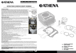
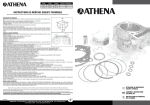
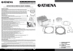
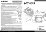
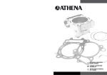
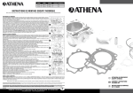
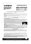
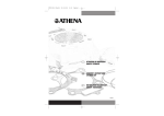
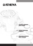
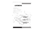
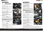
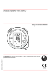
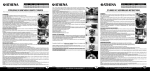
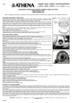
1
ALESAGE
COURSE
CYLINDREE
RAPPORT DE COMPRESSION
76 mm
55 mm
249,5 cc
12,5:1
83 mm
55 mm
297,6 cc
12,5:1
INSTRUCTIONS DE MONTAGE GROUPE THERMIQUE
Nous vous remercions pour avoir choisi nos produits et restons à votre disposition pour tous renseignements supplémentaires.
PRELIMINAIRES ET DEMONTAGE:
Démonter le siége, le réservoir et les collecteurs de décharge.
Vidanger le liquide de refroidissement.
Décrocher le flexible de reniflard d’huile moteur positionné sur le couvercle de valves et le fil du compresseur
manuel.
Démonter le couvercle de valves, la bougie et le carburateur.
Enlever le raccord de refoulement d’huile moteur de la culasse.
Mettre le piston au point mort haut pendant la phase d’explosion (fig.1).
Contrôler le jeu des valves (aspiration 0,10-0,15 mm – décharge 0,15-0,20 mm).
Enlever le tendeur de la chaîne de distribution.
Détacher les manchons de la partie inférieure du cylindre et de la culasse.
Enlever les arbres à cames, s’assurant que la position des supports ne soit pas changée.
Enlever les deux vis inférieurs de la pompe à eau et défiler la pompe de la culasse en soutenant la chaîne de
distribution.
Desserrer les vis M6 qui fixent la culasse au cylindre et le cylindre à l’embase.
Enlever la patte antérieure de la chaîne de distribution.
Enlever les vis de serrage de la culasse.
Enlever la culasse, le cylindre et le goujon. Défiler l’axe et enlever le piston.
Contrôler les composants suivants: détérioration du pied et de la tête de bielle, nettoyer le ciel de la culasse
de possibles incrustations. Vérifier l’étanchéité et le jeu des soupapes ensuivant les instructions du manuel
d’emploi et d’entretien du conducteur. La fiabilité du moteur dépend directement de la bonne qualité de ces
composants.
N.B. Réutiliser du cylindre originel les deux raccords en aluminium pour la connexion des tuyaux de refroidissement.
1
2
MONTAGE DU GROUPE THERMIQUE:
Nettoyer bien tous les plans d’appui.
Laver soigneusement tous les composants nouveaux et les souffler avec d’air comprimé.
Assembler les segments sur le piston neuf comme indiqué sur la figure 2.
Installer le piston neuf s’assurant du correct positionnement des goujons.
Positionner le joint d’embase.
Assembler les raccords en aluminium dans le cylindre, le cylindre même après avoir huilé la canne.
Assembler le joint culasse, la culasse et serrer les écrous en ordre croisé et graduel à 55 N•m (M10), 24 N•m (M8), 10 N•m (M6).
Assembler les manchons dans la partie inférieure du cylindre.
Assembler le bouchon de vidange du liquide de refroidissement avec un joint d’étanchéité nouveau.
Installer le raccord de refoulement d’huile moteur avec deux joints d’étanchéité nouveaux.
Mettre le piston au point mort haut.
Installer la patte antérieure de la chaîne de distribution.
Installer l’engrenage de renvoi de la distribution avec les deux points de repère tournés vers l’haut et la partie antérieure de la chaîne bien tendue.
Installer la pompe à eau et le manchon supérieur en serrant les vis à 10 N•m.
Détendre le tendeur de chaîne, assembler-le dans le cylindre avec son joint, serrer les écrous à 10 N•m, assembler le ressort et le bouchon.
Assembler les arbres à cames avec les pointeaux de référence alignés au plan d’appui du couvercle de valves et tournés vers l’extérieur.
Assembler les supports des arbres à cames en serrant les vis graduellement à 10 N•m.
Assembler le couvercle des valves et le flexible de reniflard d’huile moteur.
Installer le câble de actionnement du décompresseur manuel en laissant un jeu libre de 5 mm mesuré sur le câble.
Assembler le carburateur, la bougie et sa prise et les collecteurs de décharge.
Ajouter le liquide de refroidissement jusqu’au niveau du goulot de remplissage.
Remplacer l’huile moteur et le filtre.
Assembler le réservoir et le siége.
RODAGE, USAGE ET ENTRETIEN:
Pour le rodage et l’entretien conformez-vous strictement au “MANUEL D’USAGE ET D’ENTRETIEN DU CONDUCTEUR”. Utiliser des essences avec au
moins 96 octanes. Ne forcer pas le moteur pendant les premières 2-3 heures de course parce qu’on peut endommager le groupe thermique. On obtient
les meilleures performances seulement après unbon rodage. Il est nécessaire de remplacer le piston au premiers signales de fatigue du groupe thermique pour ne pas compromettre la rotondité de la chemise du cylindre.Limite de service du piston:le piston doit être remplacé après 15 heures de
course.
Nous tenons à vous rappeler que l’accessoire à lui seul ne suffit pas, et qu’un montage correct donnera à votre scooter ses meilleures performances.
On recommande vivement que l’assemblage des produits inclus dans le kit soit fait par des techniciens spécialisés: si à cause d’une mauvaise installation on
surgira des problèmes, nous déclinerons toute responsabilité pour tous les dommages ou prétention techniques et économiques à notre égard.
Tout ce qui est écrit sur cette feuille d’instructions n’est pas contraignant. Athena se réserve le droit d’appliquer des modifications si elle le juge opportun, et
n’assume aucune responsabilité pour éventuelles erreurs d’impression.
Tous les produits Athena dans les cylindrées et/ou puissances supérieures à ce qu’il est prévu par le code de la route spécifique du pays d’appartenance
d’utilisateur final, ne sont destinées qu’à une utilisation dans le cadre de compétitions sportives. L’usage sur la route publique est interdit. L’usage
aéronautique et marin n’est pas indiqué. Nous nous dégageons de toute responsabilité pour toute autre utilisation.
Le client prend sur soi la responsabilité que la distribution des produits achetés de la société Athena est conforme à la législation en vigueur dans son
pays et par conséquent dégage Athena de quelconque responsabilité.
FIM/G032
ATHENA SPA - Via delle Albere, 13 - 36045 Alonte (VI) - Italy - Tel. +39-0444-727258 - Fax +39-0444-727222
www.athena-ad.com - e-mail: [email protected]
F
I
ISTRUZIONI DI MONTAGGIO
GRUPPO TERMICO
GB ASSEMBLY INSTRUCTIONS
CYLINDER KIT
F
INSTRUCTIONS DE MONTAGE
KIT CYLINDRE
ALESAGGIO
CORSA
CILINDRATA
RAPPORTO DI COMPRESSIONE
BORE SIZE
STROKE
DISPLACEMENT
COMPRESSION RATIO
76 mm
55 mm
249,5 cc
12,5:1
76 mm
55 mm
249,5 cc
12,5:1
83 mm
55 mm
297,6 cc
12,5:1
83 mm
55 mm
297,6 cc
12,5:1
ISTRUZIONI DI MONTAGGIO GRUPPO TERMICO
ASSEMBLY INSTRUCTIONS CYLINDER KIT
Athena vi ringrazia per la preferenza accordatale, rimane comunque sempre a disposizione per rispondere alle vostre esigenze. Buon lavoro!!
OPERAZIONI PRELIMINARI E SMONTAGGIO:
Smontare la sella, il serbatoio ed i collettori di scarico.
Scaricare l’impianto di raffreddamento.
Sganciare il tubo di sfiato dell’olio motore posto sul coperchio valvole ed il filo del compressore manuale.
Rimuovere il coperchio valvole, la candela ed il carburatore.
Togliere il raccordo di mandata dell’olio motore dalla testata.
Portare il pistone al P.M.S.in fase di scoppio (fig.1).
Controllare il gioco delle valvole (Aspirazione 0,10-0,15 mm - Scarico 0,15-0,20 mm).
Togliere il tendicatena di distribuzione.
Staccare i manicotti dalla parte inferiore del cilindro e dalla testata.
Togliere gli alberi a camme annotando la posizione dei supporti che non deve assolutamente essere cambiata.
Rimuovere le due viti inferiori della pompa acqua e sfilare quest’ultima dalla testata sostenendo la catena di distribuzione.
Allentare le viti M6 che fissano la testata al cilindro ed il cilindro al basamento.
Rimuovere il pattino anteriore della catena di distribuzione.
Togliere le viti di fissaggio della testata.
Rimuovere la testata, il cilindro ed il fermo dello spinotto. Sfilare lo spinotto e rimuovere il pistone.
Verificare i seguenti componenti:usura del piede e dell’occhio di biella, pulire il cielo della testata da possibili incrostazioni, verificare la tenuta e il gioco valvole attenendosi almanuale uso e manutenzione del veicolo.
L’affidabilità del vostro motore viene garantita anche dalle buone condizioni di questi componenti.
N.B. Recuperare dal cilindro originale i due raccordi in alluminio per il collegamento dei tubi dell’impianto di raffreddamento.
We thank you for choosing our products and stay at your disposal for any further information you may require.
PRELIMINARY INSTRUCTIONS AND DISASSEMBLY:
Remove the seat, the fuel tank and the exhaust manifolds.
Drain the coolant.
Disconnect the oil breather hose placed on the valve cover and the thread of the manual compressor.
Remove the valve cover, the spark plug and the carburettor.
Remove the oil delivery connection from the cylinder head.
Take the piston to the T.D.C.during the firing stroke (picture 1).
Check the clearance of the valves (suction 0,10-0,15 mm – exhaust 0,15-0,20 mm).
Remove the chain tensioner.
Detach the manifolds from the bottom part of the cylinder and from the head.
Remove the cam shafts marking the position of the supports which shall remain unchanged.
Remove the two lower screws of the water pump and slip off the pump from the head by holding up the distribution chain.
Loosen the M6 screws that fasten the head to the cylinder and the cylinder to the base.
Remove the front shoe of the distribution chain.
Remove the clamping screws from the head.
Remove the head, the cylinder and the piston circlip.Slip off the piston pin and remove the piston.
Check the following components:wear of the small and big end, clean the combustion chamber from possible
encrustations, check the tightness and the valve clearance by keeping to the maintenance manual.
The health of your engine is guaranteed by the good conditions of these elements.
N.B. Reutilize from the original cylinder the two aluminium connections to connect the pipes of the cooling
plant.
1
1
MONTAGGIO GRUPPO TERMICO:
Pulire bene tutti i piani di appoggio.
2
Lavare accuratamente tutti i particolari nuovi e soffiarli con aria compressa.
Montare i segmenti sul pistone nuovo come raffigurato nella fig. 2.
Installare il pistone nuovo accertandosi del corretto posizionamento dei fermi spinotto.
Posizionare la guarnizione base cilindro.
Montare i raccordi in alluminio nel cilindro, ed il cilindro stesso dopo aver oliato la canna.
Montare la guarnizione della testata, la testata e serrare i dadi in ordine incrociato e graduale a 55 N•m (M10), 24 N•m (M8), 10 N•m (M6).
Montare i manicotti nella parte inferiore del cilindro.
Installare il tappo di scarico del liquido di raffreddamento con una nuova guarnizione di tenuta.
Installare il raccordo di mandata dell’olio con due nuove guarnizioni di tenuta.
Portare il pistone al P.M.S.
Installare il pattino della catena di distribuzione anteriore.
Installare l’ingranaggio di rinvio della distribuzione con i due punti di riferimento rivolti verso l’alto ed il ramo anteriore della catena teso.
Installare la pompa acqua ed il manicotto superiore, serrando le viti a 10 N•m.
Scaricare il tendicatena, montarlo nel cilindro con relativa guarnizione, serrare le viti a 10 N•m, montare la molla ed il tappo.
Montare gli alberi a camme con i bulini di riferimento allineati al piano di appoggio del coperchio valvole rivolti entrambi verso l’esterno.
Montare i supporti degli alberi a camme serrando le viti gradualmente a 10 N•m.
Montare il coperchio valvole ed il tubo di sfiato dell’olio motore.
Installare il cavo di azionamento del decompressore manuale lasciando un gioco libero misurato sul cavo di 5 mm.
Montare il carburatore, la candela e relativa presa e i collettori di scarico.
Riempire il circuito di raffreddamento.
Sostituire l’olio del motore ed il filtro.
Montare il serbatoio e la sella.
ASSEMBLING INSTRUCTIONS:
Clean carefully all the bearing surfaces.
Wash carefully al the new components and blow them with compressed air.
2
Assemble the pins on the new piston as indicated in picture 2.
Install the new piston.Make sure of the correct position of the piston pins.
Install the cylinder base gasket.
Assemble the aluminium connections into the cylinder and the cylinder itself after oiling the liner.
Assemble the head gasket, the head and tighten the nuts in a cross and gradual pattern at 55 N•m (M10), 24 N•m (M8), 10 N•m (M6).
Assemble the manifolds into the bottom part of the cylinder.
Install the discharge cap of the coolant fluid with a new sealing gasket.
Install the oil delivery connection with two new sealing gaskets.
Take the piston to T.D.C.
Install the front shoe of the distribution chain.
Assemble the gear of the distribution with the two marks turned upwards and the front arm well tight.
Install the water pump and the upper manifold by tightening the screws at 10 N•m.
Let the chain tensioner run down, assemble it into the cylinder with its gasket, tighten the screws at 10 N•m, assemble the springand the cap.
Assemble the cam shafts with their centre punches aligned to the bearing surface of the valve cover and both turned outside.
Assemble the supports of the cam shafts by tightening gradually the screws at 10 N•m.
Assemble the valve cover and the oil breather tube.
Install the working cable of the manual decompressor by letting a free clearance of 5 mm measured on the cable.
Install the carburettor, the spark plug with its grip and the exhaust manifolds.
Add coolant up to the filler neck.
Replace the engine oil and the filter.
Assemble the fuel tank and the seat.
RODAGGIO, USO E MANUTENZIONE:
Per il rodaggio e la manutenzione attenersi scrupolosamente al manuale “USO E MANUTENZIONE DEL VEICOLO”. Non utilizzare benzine con meno di 96 ottani.
Non forzare ilmotore per le prime 2-3 ore d’utilizzo, poiché si rischierebbe di danneggiare il gruppo termico, inoltre le massime prestazioni si avranno dopo un
buon rodaggio. È opportuno sostituire il pistone al primo cenno di affaticamento del kit per non compromettere la rotondità della canna del cilindro. Limite di
servizio pistone:consigliamo di sostituirlo dopo 15 ore dilavoro.
RUNNING IN, USE AND MAINTENANCE:
For the running in and the maintenance follow carefully the instructions given in the manual “OWNER’S USE AND MAINTENANCE MANUAL”. Use petrol
containing at least 96octanes.Do not force the engine during the first 2-3 running hours as you can cause damages to the cylinder kit. The best performance is obtained only after a good running in. Assoon as you feel that the engine power is decreasing we suggest to replace the piston in order not to
compromise the roundness of the cylinder tube. Service piston limit:we sug-gest replacing the piston after 15 running hours.
Ci permettiamo di ricordarVi che non è il singolo pezzo, ma la completezza dell’insieme, che fa raggiungere al vostro motore il massimo delle prestazioni!
We remind you that it is not the single part but all the parts as a whole that give your engine the best performance.
Si suggerisce il montaggio dei prodotti contenuti in questo kit da parte di tecnici specializzati: se difetti e/o problemi venissero causati da una cattiva installazione, sarà declinata ogni ns. responsabilità per ogni qualsivoglia danno o pretesa tecnica ed economica nei ns confronti.
Quanto scritto su questo foglio d’istruzioni non si intende impegnativo. La ditta Athena si riserva il diritto di apportare modifiche qualora lo ritenesse necessario,
inoltre non si ritiene responsabile per eventuali errori di stampa.
Only qualified technicians must make the assembling of the articles included in this kit. In case a wrong assembling causes any faults and/or problems, we will
not be responsible for any damage or technical or economical request which are claimed to us. The descriptions contained in this leaflet are not binding. Athena
reserves the right to make any changes, if necessary. We are not responsible for any printing errors.
Tutti gli articoli ATHENA, prodotti nelle cilindrate e/o potenze superiori a quelle previste dal codice stradale del paese di appartenenza dell'utilizzatore
finale, sono destinati esclusivamente ad uso agonistico sportivo. L'uso sulla strada pubblica, come anche in campo aeronautico e marino, è vietato.
ATHENA declina ogni responsabilità per usi diversi. Il cliente si rende pertanto responsabile che la distribuzione degli articoli acquistati da Athena sia
conforme alla legislazione vigente nel proprio paese, liberando la stessa da qualsivoglia responsabilità.
FIM/G032
ATHENA SPA - Via delle Albere, 13 - 36045 Alonte (VI) - Italy - Tel. +39-0444-727258 - Fax +39-0444-727222
www.athena-ad.com - e-mail: [email protected]
I
All ATHENA products, which are manufactured with higher displacement and power than those permitted by law of the country where the end user lives,
are intended solely for competition-sports usage. Use on public roads as well as in aeronautics and marine is prohibited. ATHENA is not responsible for
any different usage.
The customer takes full responsibility that the distribution of the articles purchased from Athena is in line with the current regulations of his country and
therefore frees Athena from whatever esponsibility in this matter.
FIM/G032
ATHENA SPA - Via delle Albere, 13 - 36045 Alonte (VI) - Italy - Tel. +39-0444-727258 - Fax +39-0444-727222
www.athena-ad.com - e-mail: [email protected]
GB