1
Prefazione
10-01-2006
15:26
Pagina 1
Scatole di derivazione
Edition 2006
Junction boxes
Edizione 2006
quipment installed in areas with risk of explosion and fire must
be considered safe for the community, so they must be chosen by companies which are able to accompany the product with
a certificate of compliance with international standards. This certificate must be issued by competent and government authorized
laboratories, along with a test report to prove that the product is
totally safe and suitable for installation on the system concerned.
For self-certified safety materials “n” (no-sparking), it is advisable to ask for internal test reports.
E
ortem’s lighting fixtures are made of extremely resistant borosilicate glass tubes and globes and copper-free Al-Si12 aluminium alloy bodies. Aluminium-silicon alloy is one of the most prestigious families in aluminium casting. Noted for its high mechanical strength, sufficient malleability and compactness, this alloy is
highly corrosion resistant, as proved by corrosion tests in saline
mist, hydrogen sulphide current, hydrochloric acid aqueous solution and galvanic current. Furthermore, aluminium alloy is impermeable and highly resistant to thermal shocks and high pressures;
it is also a noise and vibration reducer and does not oxidize in very
damp atmospheres, so it is highly durable and can be recycled
forever without losing its quality and properties.
C
e apparecchiature installate nei luoghi con pericolo di esplosione e incendio devono essere considerate una sicurezza per
la comunità, pertanto la corretta scelta deve essere fatta verso
quelle Aziende in grado di accompagnare al prodotto il relativo
certificato di conformità alle normative internazionali redatto da
laboratori competenti e autorizzati a livello governativo all’emissione di tali documenti che dimostrano il resoconto delle prove effettuate e quindi la completa sicurezza del prodotto e idoneità ad
essere installato sull’impianto relativo.
Per materiali a sicurezza “n” (non scintillanti) in autocertificazione si consiglia di richiedere i test report di prova elaborati intermente.
L
e armature illuminanti Cor.tem, sono costruite con globi e tubi di
vetro in borosilicato ad altissima resistenza e con corpi in lega
di alluminio Al-Si12 esenti da rame. Questa lega di alluminio-silicio
rappresenta una delle più prestigiose famiglie nel campo della fonderia di alluminio. Infatti vanta una resistenza meccanica elevata,
sufficiente duttilità, buona compattezza e inoltre le prove di corrosione in nebbia salina, in corrente di acido solfidrico, soluzione
acquosa di acido cloridrico e in corrente galvanica, hanno confermato una gran resistenza alla corrosione. Altre importanti caratteristiche di questa lega di alluminio sono: impermeabilità, resistenza
agli shock termici, resistenza a pressioni elevate, riduzione di rumori e di vibrazioni, inoltre non si ossida in zone climatiche molte
umide e quindi ha una vita più lunga, è riciclabile all’infinito e non
perde ne qualità ne proprietà.
L
Appendice 10-11-2005 12:58 Pagina 2
The Group
Il Gruppo
i-tech research into safer, quality products and the need to
address increasingly specific market requirements have
led Cortem, Elfit and Fondisonzo to merge forces in the aim to
satisfy the market more quickly and efficiently. While maintaining
their production specializations, which represent their history
and guarantee product quality, these three companies have
merged to form the to work towards important international
objectives. The group’s extensive range of products allows it to
specialize more in niche markets.
Cortem is specialized in manufacturing lighting fixtures and
light and sound warning devices with EEx-d, EEx-e, EEx-n and
watertight protection.
Fondisonzo is specialized in manufacturing plugs and socket-outlets, boxes, control and signalling panels with EEx-d, EEx-e, EEx-i
and watertight protection.
Elfit is specialized in manufacturing fittings and cable glands
with EEx-d, EEx-e, EEx-i and watertight protection.
The is dedicated to researching and developing new improved
solutions for every niche of the new industrial market as well as
providing a better customer service. As leading manufacturers
in the design and manufacture of anti-combustible electrical
equipment, we employ only highly skilled, professional staff and
qualified suppliers. Our joint goal is to achieve the highest standards in both
product quality
and
internal
organization by
constantly
improving our
manufacturing
processes and
services.
H
a ricerca di nuove tecnologie per prodotti di qualità più sicuri e le richieste del settore sempre più specifiche, hanno
spinto Cortem, Elfit e Fondisonzo ad unire le forze per arrivare
sul mercato prima ed in modo più efficace. Mantenendo la propria identità costruttiva, che rappresenta la storia di un’azienda
e la garanzia della qualità dei prodotti, le tre Società entrano
nella sinergia di gruppo per il raggiungimento di importanti
obiettivi internazionali.
L
La gamma di prodotti offerti permette un’ampia scelta e dà l’opportunità al nuovo Gruppo di specializzarsi sempre più in segmenti di mercato ben precisi.
Cortem, specializzata nella produzione di armature illuminanti,
avvisatori acustici e luminosi in esecuzione EEx-d, EEx-e, EEx-n
e stagna.
Fondisonzo, specializzata nella produzione di prese e spine,
cassette, pulsantiere di comando e segnalazione in esecuzione
EEx-d, EEx-e, EEx-i e stagna.
Elfit specializzata nella produzione di raccorderie e pressacavi
in esecuzione EEx-d, EEx-e, EEx-i e stagna.
La ricerca e la proposta di nuove e migliori soluzioni è un atteggiamento che guida in ogni segmento del nuovo assetto industriale. Il risultato si traduce in un impegno per un miglior servizio alla nostra clientela. Come produttori leader nella progettazione e fabbricazione di equipaggiamenti elettrici antideflagranti, ci impegnano a considerare la qualità e la professionalità del
nostro personale, mantenendo la condizione di fornitori qualificati e concentrando questa sinergia al raggiungimento di standard di eccellenza, sia sul prodotto che nell’organizzazione
interna attraverso continui miglioramenti del processo produttivo
e delle funzioni aziendali.
Appendice 10-11-2005 12:58 Pagina 3
Company History
The Company was established by Mr. Marco Rossi and Renato Gratton, who thus joined
and put to good use the technical and commercial experience that they had acquired in
the past while managing the Company CROUSE HINDS ITALIA.
ELFIT was established by Mr. Marco Rossi, Renato Gratton and Silvano Lorenzon, as a
sister Company, in order to improve the production cycle; the aluminium fusion quality
and the manufacturing of electrical and watertight fittings in particular.
The first increased safety lighting fixture, series AVF, was designed.
The electronic grounding system GRD-4200 for tanks and tankers was born in 1985, as
a sample of technological innovation.
The reflector RLEE-107 was designed for incandescent lamps up to 1000 W.
The increased safety lighting fixture in aluminium alloy, series LX, was first designed and
manufactured.
The Company Quality System was certified by DNV according to the European regulation
UNI EN 29002 (ISO 9002); two years later we obtained the certification UNI EN ISO 9001.
Cortem was awarded by SNAMPROGETTI Milan a supply contract for BANDAR ABBAS
Refinery in Iran, for the value of 1.600.000 USD. CORTEM UK Ltd was established to
expand the market for our products in the United Kingdom, in the same year.
Cortem was awarded a big supply contract by TECHNIP ITALY for MIDOR Refinery in
Alexandria, Egypt, for the value of 1,200,000 USD. The first multi-range, double channel
electronic ballast for fluorescent lighting fixtures was designed in cooperation with a
worldwide known manufacturer.
The Company obtained CESI certification for the production quality, according to the
directive 94/9/CE (ATEX). Cortem expanded its sales offices in Milan, which were equipped and wired for HDSL transmission technology and a screen conference system, thus
enabling the connection with the production sectors in the headquarter and the major
clients, for a better technical support. Cortem designed the electronics PCB circuits used
to control and synchronize the led diode signalling lights.
Cortem brought out the first explosion proof cable gland for armoured cable, ATEX certified. The Company interactive website was realized besides the informative and technical portal www.exproof.net
Some products were certified according to the Russian (GOST R and GOSGORTECHNADZOR) regulations. Cortem started manufacturing the one-off model of the explosion
proof socket and plug 16A, small size and the pins in accordance with CEE regulations.
TECHNIP FRANCE awarded Cortem a contract for the 9 OLEFIN ETHANE CRACKING
PLANT in NARGAN, IRAN.
1968
1977
1985
1988
1989
1994
1998
1999
2000
2001
2002
La nostra evoluzione
L’azienda viene costituita dai Sigg. Marco Rossi e Renato Gratton, che uniscono la loro
esperienza tecnica e commerciale maturata negli anni precedenti, come dirigenti, della
società CROUSE HINDS ITALIA.
Nasce la società ELFIT, costituita dai Sigg. Marco Rossi, Renato Gratton e Silvano
Lorenzon, con l’esigenza di poter controllare i processi produttivi, la qualità delle fusioni
di alluminio e della produzione di raccorderie, elettriche e stagne. Viene realizzata la
prima armatura illuminante a sicurezza aumentata, serie AVF.
Nasce un prodotto innovativo: il sistema di messa a terra elettronico per autobotti e serbatoi, GRD-4200.
Viene progettato, il proiettore RLEE-107 per lampade fino a 1000W ad incandescenza.
Viene realizzata la prima armatura illuminante in lega di alluminio, a sicurezza aumentata, serie LX
Certificazione del sistema di qualità secondo la normativa UNI EN 29002 (ISO 9002) e
due anni dopo la certificazione UNI EN ISO 9001, dal DNV.
L’azienda acquisisce dalla SNAMPROGETTI di Milano una importante fornitura per la raffineria di BANDAR ABBAS in IRAN del valore di 1.600.000 USD. Nello stesso anno viene
costituita la società Cortem UK Ltd, per lo sviluppo del mercato inglese.
L’azienda acquisisce dalla TECHNIP ITALY una importante fornitura per la raffineria
MIDOR ad Alessandria (EGITTO) del valore di 1.200.000 USD. Insieme ad uno dei più
importanti costruttori mondiali, viene realizzato il primo reattore elettronico bicanale multirange per lampade fluorescenti.
Notifica CESI di garanzia della qualità della produzione secondo la direttiva 94/9/CE
(ATEX). Gli uffici commerciali di Milano si ampliano e vengono cablati con gli stabilimenti, sfruttando tecnologie di trasmissione HDSL e video conferenza per il collegamento con
i reparti produttivi dello stabilimento e con i clienti per il supporto tecnico avanzato.
Vengono sviluppati i moduli elettronici e le logiche per il controllo e la sincronizzazione
delle lampade di segnalazione a diodi led.
Nasce il primo pressacavo barriera antideflagrante, certificato secondo la direttiva ATEX.
Viene realizzato il primo sito web aziendale interattivo www.cortem.com ed il primo portale tecnico e d’informazione www.exproof.net
Certificazione dei prodotti secondo le norme russe (GOST R e GOSGORTECHNADZOR).
Viene avviata la produzione dell’esclusiva presa e spina antideflagrante da 16A con disposizione dei poli a norma CEE.
L’azienda acquisisce da TECHNIP FRANCE una commessa per l’impianto 9 OLEFIN
ETHANE CRACKING PLANT di NARGAN in IRAN.
Cortem obtained DNV’s certification of the Quality System, according to the regulation
UNI EN ISO 9001:2000 (VISION 2000) and the certificates for the Australian market (in
accordance to IEC regulations) and Kazakhs (GOST K).
Cortem patented the first lighting fixture with led diode light, for obstacle signalling in the
airports. Cortem was awarded a contract for the value of 3.800.000 USD by SNAMPROGETTI MILAN for the ARAMCO QATIF PROJECT in SAUDI ARABIA, besides a big job
through TECHNIP FRANCE and SP-TKP for the OMIFCO’s OMAN/INDIA FERTILIZER PROJECT in INDIA for the value of 1.800.000 USD.
2003
Certificazione del sistema di qualità secondo la normativa UNI EN ISO 9001:2000
(VISION 2000) e certificati per i mercati, Australiano (in accordo alle normative IECI) e
Kazako (GOST K). Brevettata la prima armatura illuminante con lampada a diodi led, per
aeroporti e la segnalazione ostacoli.
L’azienda acquisisce dalla SNAMPROGETTI di Milano una importante fornitura per l’impianto di QATIF di ARAMCO in ARABIA SAUDITA del valore di 3.800.000 USD e un’altra
grossa commessa da TECHNIP FRANCE e SP-TKP per l’impianto OMAN/INDIA FERTILIZER PROJECT di OMIFCO in INDIA del valore di 1.800.000 USD.
CORTEM VENEZUELA was established to expand the market in Venezuela and South
America.
Cortem acquired a supply contract for 700,000 USD through TECHNIP FRANCE for the
JAM PETROCHEMICAL COMPANY’s plant 10 OLEFIN COMPLEX in IRAN.
2004
2005
Costituzione della società CORTEM VENEZUELA, per lo sviluppo del mercato Venezuelano
e sudamericano. L’azienda acquisisce dalla TECHNIP FRANCE una importante commessa per la fornitura dell’impianto 10 OLEFIN COMPLEX di JAM PETROCHEMICAL COMPANY in IRAN del valore di 700.000 USD.
Hi-tech research into safer, first-rate products and the incresingly incoming field
requirements led to establish Cortem Group. Cortem, Elfit and Fondisonzo joint
their forces to satisfy the market quickly and effectively.
Nasce Cortemgroup dall'esigenza di ricercare sempre nuove tecnologie per
prodotti di qualità più sicuri e dalle richieste del settore sempre più specifiche.
Cortem, Elfit e Fondisonzo uniscono le forze in un unico gruppo per arrivare sul
mercato prima ed in modo più efficace.
Appendice 10-11-2005 12:58 Pagina 4
United we stand for you to test us out
Uniti per voi…Metteteci alla prova
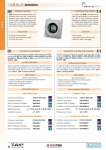
Special execution
Cortem Group are also specialized
in designing and manufacturing
special assemblies in explosionproof execution according to
customers’ specifications, such as
panel boards for the control and
signal of lighting systems, motive
powers and obstruction lighting fixtures...
Esecuzioni speciali
La Cortem Group é anche specializzata nella progettazione e realizzazione di prodotti speciali in esecuzione antideflagrante e su specifica
del Cliente; in particolare vengono
prodotti quadri elettrici per impianti
luce e forza motrice, batterie di
comando e segnalazione, armature
illuminanti per segnalazione ostacoli...
Cable glands, electrical fittings
and flexible conduits for electrical
systems.
Cortem designs and manufactures
a wide range of cable glands, realized in various materials in EEx-d,
EEx-e, EEx-i execution and IP65
protection, together with fittings
and connecting conduits both rigid
and flexible, for the realization of
complete piping electrical systems.
Pressacavi, raccorderia e tubi flessibili per impianti elettrici.
Offriamo una vasta gamma di pressacavi in esecuzione EEx-d, EEx-e,
EEx-i, IP65, con diversi tipi di materiali, insieme alla raccorderia e ai
tubi flessibili o rigidi, di collegamento, che vengono impiegati per la
realizzazione di un completo
impianto elettrico in tubo.
Instruments housings, acoustic
signals and grounding equipments.
Cortem designs and manufactures
cases in EEx-d execution that are
apt to house analogical and digital
precision instruments, thus helping
the measurement and the control
of the industrial production process, both visual and acoustic. We
also produce systems that are able
to grant the grounding of tanks and
tankers while loading and unloading inflammables.
Cassette portastrumenti, segnalatori acustici e sistemi di messa a terra
Realizziamo custodie in esecuzione
EEx-d atte a contenere strumenti di
misura analogici e digitali per rendere più agevole le attività di misurazione e controllo dei processi
industriali, sia nel controllo visivo
che acustico, nonché sistemi che
assicurano la messa a terra delle
cisterne e autobotti durante le operazioni di carico e scarico di liquidi
infiammabili.
Appendice 10-11-2005 12:58 Pagina 5
The Poduction
Push button and signalling units,
switches, receptacles and plugs.
We offer a whole range of switches,
control and signalling stations in
EEx-d, EEx-e execution and IP65
protection, for any kind of industrial
plant. Moreover, we manufacture
control switches for the supply of
electrical circuits and motive power,
besides several patterns of electrical sockets and plugs with either
automatic or interlocked switch.
Junction boxes and pulling boxes.
The junction and pulling boxes are
manufactured in various materials,
in EEx-d, EEx-e, EEx-i execution
and IP65 protection. They are suitable for all industrial plants at risk of
explosion and are apt to hold switching terminals, switches, control
and signalling push buttons to realize panel boards and control batteries in EEx-d, EEx-de execution.
Pulsantiere, manipolatori, interruttori di comando e prese di corrente...
Disponiamo di una gamma completa di pulsantiere, manipolatori di
comando segnalatori in esecuzione
EEx-d, EEx-e, IP65 per qualsiasi
tipo di applicazione industriale,
insieme agli interruttori di comando
per l’alimentazione di circuiti luce o
forza motrice, insieme alle prese e
spine di corrente sia con interruttore interbloccato che automatico
realizzate in diverse configurazioni.
Custodie, cassette di infilaggio e
derivazione
Le custodie e cassette di derivazione, realizzate in esecuzione EEx-d,
EEx-e, EEx-i, IP65 e in diversi tipi di
materiali, trovano applicazione in
tutti gli ambienti industriali a rischio
di esplosione e stagni; sono
costruite per contenere morsettiere
di smistamento, interruttori, pulsanteria di comando e segnalazione
specialmente per la realizzazione
di quadri elettrici e batterie di
comando in esecuzione EEx-d,
EEx-de.
La produzione
Prefazione
24-01-2006
18:34
Pagina 6
Contents - Indice
Code - Codice
EJB-1
EJB-1P
EJB-2
EJB-2P
EJB-3B
EJB-3
EJB-3BP
EJB-3P
EJB-4B
EJB-4
EJB-4BP
EJB-4P
EJB-45B
EJB-45
EJB-45BP
EJB-45P
EJB-5B
EJB-5
EJB-5BP
EJB-5P
EJB-503
EJB-6B
EJB-6
EJB-01
AQS-1
EJBX-1
EJBX-2
EJBX-3
EJBX-3B
EJBX-4
EJBX-4B
EJBX-45
EJBX-45B
EJBX-5
EJBX-5B
EJBX-6
EJBX-6B
GUB
GUB-S
GUB-0
GUB-01
GUB-02
GUB-03
GUB-04
GUB-0V
GUB-01V
GUB-02V
GUB-03V
GUB-04V
CCA-0E
CCA-01E
CCA-02E
CCA-03E
CCA-04E
CCA-0EH
CCA-01EH
CCA-02EH
CCA-03EH
CCA-04EH
CCA-0C
CCA-01C
CCA-02C
CCA-03C
CCA-04C
CCAI-2020
Protection - Protezione
EEx d
EEx d
Pag.
2
12
EEx d
22
EEx d
28
EEx d
32
EEx d
38
EEx d
42
EEx d
50
Code - Codice
CCAI-3020
CCAI-3030
CCAI-4030
CCAI-4040
SA-…
SC- …
SL- …
SX- …
ST- …
SB- …
SD- …
SM- …
SW- …
SFC-…
SFL- …
SFT- …
SFX- …
SSC-…
SA090907
SA111108
SAG111108
SA171108
SAG171108
SA141410
SAG141410
SA301410
SAG301410
SA302310
SAG302310
SA302318
SAG302318
SA473018
SAG473018
SAG623018
SA090907/P
SA111108/P
SA171108/P
SA141410/P
SA301410/P
SA302310/P
SA302318/P
SA473018/P
SA623018/P
SA111108SS..
SA171108SS..
SA141410SS..
SA301410SS..
SA302310SS..
SA302318SS..
SA404020SS..
SA473018SS..
SA623018SS..
SA606020SS..
CSTB 121208
CSTB 151509
CSTB 191910
CTB 221513
CTB 262616
CTB 262620
CTB 303016
CTB 303020
CTB 382616
CTB 382620
CTB 453816
CTB 453820
Protection - Protezione
Pag.
EEx d
50
EEx d
56
EEx d
60
EEx e
72
EEx e
76
EEx e
80
EEx e
90
Prefazione
20-01-2006
16:52
Pagina 7
Contents - Indice
Code - Codice
CTB 484816
CTB 484820
CTB 503516
CTB 503520
CTB 624516
CTB 624520
CTB 745520
CTB 765020
CTB 866420
CTB 916120
CTB 987420
CS111108SS..
CS171108SS..
CS141410SS..
CS301410SS..
CS302310SS..
CS302318SS..
CS404020SS..
CS473018SS..
CS623018SS..
CS606020SS..
CS090907
CS111108
Protection - Protezione
EEx e
Pag.
90
Watertight IP
Stagna IP
Watertight IP
Stagna IP
98
104
Code - Codice
CSG111108
CS171108
CSG171108
CS141410
CSG141410
CS301410
CSG301410
CS302310
CSG302310
CS302318
CSG302318
CS473018
CSG473018
CSG623018
CS090907/P
CS111108/P
CS171108/P
CS141410/P
CS301410/P
CS302310/P
CS302318/P
CS473018/P
CS623018/P
Protection - Protezione
Pag.
Watertight IP
Stagna IP
104
Watertight IP
Stagna IP
106
EEx d protection - Protezione EEx d
CHAPTER - CAPITOLO
PAG.
• EJB . . . . . . . . . . . . . . . . . . . . . . . . . . . . . . . . . . . . . . . . . . . . . . . . . . . . . . . . . . . . . . . . . . . . . . . . . . . . . . . . . . . . . . . . . . . . . . . . . . . .
2
• EJBX . . . . . . . . . . . . . . . . . . . . . . . . . . . . . . . . . . . . . . . . . . . . . . . . . . . . . . . . . . . . . . . . . . . . . . . . . . . . . . . . . . . . . . . . . . . . . . . . . . .
12
• GUB . . . . . . . . . . . . . . . . . . . . . . . . . . . . . . . . . . . . . . . . . . . . . . . . . . . . . . . . . . . . . . . . . . . . . . . . . . . . . . . . . . . . . . . . . . . . . . . . . . .
22
• GUB…V . . . . . . . . . . . . . . . . . . . . . . . . . . . . . . . . . . . . . . . . . . . . . . . . . . . . . . . . . . . . . . . . . . . . . . . . . . . . . . . . . . . . . . . . . . . . . . . .
28
• CCA…E . . . . . . . . . . . . . . . . . . . . . . . . . . . . . . . . . . . . . . . . . . . . . . . . . . . . . . . . . . . . . . . . . . . . . . . . . . . . . . . . . . . . . . . . . . . . . . . . .
32
• CCA…EH . . . . . . . . . . . . . . . . . . . . . . . . . . . . . . . . . . . . . . . . . . . . . . . . . . . . . . . . . . . . . . . . . . . . . . . . . . . . . . . . . . . . . . . . . . . . . . .
38
• CCA…C . . . . . . . . . . . . . . . . . . . . . . . . . . . . . . . . . . . . . . . . . . . . . . . . . . . . . . . . . . . . . . . . . . . . . . . . . . . . . . . . . . . . . . . . . . . . . . . .
42
• CCA…I . . . . . . . . . . . . . . . . . . . . . . . . . . . . . . . . . . . . . . . . . . . . . . . . . . . . . . . . . . . . . . . . . . . . . . . . . . . . . . . . . . . . . . . . . . . . . . . . .
50
• S… . . . . . . . . . . . . . . . . . . . . . . . . . . . . . . . . . . . . . . . . . . . . . . . . . . . . . . . . . . . . . . . . . . . . . . . . . . . . . . . . . . . . . . . . . . . . . . . . . . . .
56
• SF…SSC . . . . . . . . . . . . . . . . . . . . . . . . . . . . . . . . . . . . . . . . . . . . . . . . . . . . . . . . . . . . . . . . . . . . . . . . . . . . . . . . . . . . . . . . . . . . . . . .
60
• Terminals tables - Tabelle morsetti . . . . . . . . . . . . . . . . . . . . . . . . . . . . . . . . . . . . . . . . . . . . . . . . . . . . . . . . . . . . . . . . . . . . . . . . . . .
64
EEx e protection - Protezione EEx e
• SA…SAG . . . . . . . . . . . . . . . . . . . . . . . . . . . . . . . . . . . . . . . . . . . . . . . . . . . . . . . . . . . . . . . . . . . . . . . . . . . . . . . . . . . . . . . . . . . . . . . .
72
• SA…/P . . . . . . . . . . . . . . . . . . . . . . . . . . . . . . . . . . . . . . . . . . . . . . . . . . . . . . . . . . . . . . . . . . . . . . . . . . . . . . . . . . . . . . . . . . . . . . . . .
76
• SA…SS . . . . . . . . . . . . . . . . . . . . . . . . . . . . . . . . . . . . . . . . . . . . . . . . . . . . . . . . . . . . . . . . . . . . . . . . . . . . . . . . . . . . . . . . . . . . . . . . .
80
• CTB - CSTB . . . . . . . . . . . . . . . . . . . . . . . . . . . . . . . . . . . . . . . . . . . . . . . . . . . . . . . . . . . . . . . . . . . . . . . . . . . . . . . . . . . . . . . . . . . . .
90
Watertight IP protection - Protezione stagna IP
• CS…SS . . . . . . . . . . . . . . . . . . . . . . . . . . . . . . . . . . . . . . . . . . . . . . . . . . . . . . . . . . . . . . . . . . . . . . . . . . . . . . . . . . . . . . . . . . . . . . . . .
98
• CS…CSG . . . . . . . . . . . . . . . . . . . . . . . . . . . . . . . . . . . . . . . . . . . . . . . . . . . . . . . . . . . . . . . . . . . . . . . . . . . . . . . . . . . . . . . . . . . . . . .
104
• CS…/P . . . . . . . . . . . . . . . . . . . . . . . . . . . . . . . . . . . . . . . . . . . . . . . . . . . . . . . . . . . . . . . . . . . . . . . . . . . . . . . . . . . . . . . . . . . . . . . . .
106
Supplement - Appendice
• General installation regulation - Norme generali di installazione . . . . . . . . . . . . . . . . . . . . . . . . . . . . . . . . . . . . . . . . . . . . . . . . . . . . . . . .
110
01 EEX D-6
20-01-2006
16:39
Pagina 2
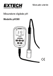
E J B . . . Series/Serie
EEx d
TECHNICAL FEATURES
CARATTERISTICHE TECNICHE
EJB… series aluminium alloy enclosures
are used both as junction enclosures with
or without terminals and for installing other
electrical equipment such as switches,
indicators, section switches, remote control switches and transformers. Enclosures
can be drilled and threaded both on walls
and covers according to customer specifications.
Le custodie della serie EJB… costruite in
lega di alluminio vengono impiegate sia
come cassette di derivazione con o senza
morsetti, sia per l’installazione di altri apparati elettrici come interruttori, segnalatori,
sezionatori, teleruttori, trasformatori, ecc.,
sia per la realizzazione di quadri elettrici.
Le custodie possono essere forate e filettate sia sulle pareti che sui coperchi, su specifica del cliente.
ACCESSORI
ACCESSORIES
• Kit IP66/67
• Telaio interno
• Verniciatura interna anticondensa
• Valvola di sfiato e drenaggio
• IP66/67 kit
• Internal mounting plates
• Internal anti-condensate coating
• Air and drainage valve
CONFORMITY TO STANDARDS
CONFORMITA’ ALLE NORMATIVE STANDARD
Explosion-proof enclosures built to CENELEC standards EN 50014:
1997 + A1…A2, EN 50018: 1994/2000, IEC60079-0: 2004, IEC
60079.1: 2004, EN 50281-1-1: 1998 + A1 and EUROPEAN DIRECTIVE
94/9/EC: 1994.
Custodie a prova di esplosione costruite in accordo alle normative
CENELEC EN 50014: 1997 + A1…A2, EN 50018: 1994/2000,
IEC60079-0: 2004, IEC 60079.1: 2004, EN 50281-1-1: 1998 + A1 ed
alla DIRETTIVA EUROPEA 94/9/EC: 1994.
INSTALLATION AREAS
LUOGHI DI INSTALLAZIONE
These enclosures are designed for use indoors or outdoors in potentially hazardous atmospheres containing explosive or combustible
gases and dusts. They are installed in the following zones: zone 1,
zone 2, zone 21, zone 22.
Le custodie vengono usate in luoghi pericolosi all’interno o all’esterno dove esiste pericolo di esplosioni o combustioni di gas e di polveri combustibili, vengono installate nelle seguenti zone: zona 1,
zona 2, zona 21, zona 22.
APPLICATIONS
APPLICAZIONI
Atmosfera esplosiva
Potentially explosive atmospheres
- chemical, petrochemical and pharmaceutical industries;
- onshore and offshore ship industries;
- areas with risks of explosion and fire;
- OIL and GAS industries.
- industrie chimiche, petrolchimiche e farmaceutiche;
- onshore ed offshore, navale;
- luoghi con pericolo di esplosione ed incendio;
- industrie OIL and GAS.
CERTIFICATION AND USE
CERTIFICAZIONI ED ESECUZIONE
EMPTY ENCLOSURES
CUSTODIE VUOTE
CE test certification:
CESI 00 ATEX 036U
Certificato di esame CE del tipo:
CESI 00 ATEX 036U
Australian Certification:
AVAILABLE
Certificato Australiano:
DISPONIBILE
GOST R (Russia) Certification:
AVAILABLE
Certificato GOST R (Russia):
DISPONIBILE
GOST K (Kazakhstan) Certification:
AVAILABLE
Certificato GOST K (Kazhakistan): DISPONIBILE
II 2 GD EEx d IIB IP65
Esecuzione
0722 Execution:
0722:
Custodie con grasso al silicone
per la tenuta IP con o senza operatori
Enclosures with silicone grease
with or without equipment
II 2 GD EEx d IIB IP66/67
II 2 GD EEx d IIB IP66/67
Custodie con guarnizione di tenuta senza
operatori di comando e segnalazione
Sealed enclosures without
signal and control equipment
II 2 GD EEx d IIB IP66
II 2 GD EEx d IIB IP66
Sealed enclosures with M-0
signal and control equipment
II 2 GD EEx d IIB IP65
Custodie con guarnizione di tenuta con operatori
di comando e segnalazione tipo M-0
Protection:
IP65 / 66 / 67
Grado di protezione:
IP65 / 66 / 67
Ambient Temperature:
-20 +55°C
Temperatura ambiente:
-20 ÷ +55°C
2
Explosion Proof Electrical Fittings
Safety Equipment for Hazardous Areas
01 EEX D-6
20-01-2006
16:37
Pagina 3
CERTIFICATION AND USE
CERTIFICAZIONI ED ESECUZIONE
ENCLOSURES WITH TERMINALS
CUSTODIE CON MORSETTI
CE test certification:
CESI 01 ATEX 026
Certificato di esame CE del tipo:
CESI 01 ATEX 026
Australian Certification:
AVAILABLE
Certificato Australiano:
DISPONIBILE
GOST R (Russia) Certification:
AVAILABLE
Certificato GOST R (Russia):
DISPONIBILE
GOST K (Kazakhstan) Certification:
AVAILABLE
Certificato GOST K (Kazhakistan): DISPONIBILE
II 2 G EEx d IIB
Esecuzione
0722 Execution:
0722 :
Explosion-proof enclosures
II 2 G EEx d IIB
Custodie protette solo contro i gas infiammabili
II 2 GD EEx d IIB IP65
II 2 GD EEx d IIB P65
Enclosures with silicone grease
Custodie con grasso al silicone
II 2 GD EEx d IIB P66/67
II 2 GD EEx d IIB IP66/67
Sealed enclosures
Protection:
EEx d
E J B . . . Series/Serie
Custodie con guarnizione di tenuta
Grado di protezione:
IP66 / 65 / 66
IP66 / 65 / 66
Maximum surface temperature with GD terminal enclosures:
• T6 for ambient temperature -20 +40°C
• T5 for ambient temperature -20 +55°C
Massima temperatura superficiale con morsettiere di categoria GD:
• T6 per temperatura ambiente -20 ÷ +40°C
• T5 per temperatura ambiente -20 ÷ +55°C
Maximum surface temperature with D terminal enclosures:
• T85°C for ambient temperature -20 +40°C
• T100°C for ambient temperature -20 +55°C
Massima temperatura superficiale con morsettiere di categoria D:
• T85°C per temperatura ambiente -20 ÷ +40°C
• T100°C per temperatura ambiente -20 ÷ +55°C
Ambient Temperature:
Temperatura ambiente:
-20 +40°C
-20 +55°C
ELECTRICAL SPECIFICATIONS
-20 ÷ +40°C
-20 ÷ +55°C
CARATTERISTICHE ELETTRICHE
Rated voltage:
24 800V
Tensione nominale:
24 ÷ 800V
Rated frequency:
50 60Hz
Frequenza nominale:
50 ÷ 60Hz
MODULAR TERMINALS
MORSETTI COMPONIBILI
Terminals section: 2.5; 4; 6; 10; 16; 25; 35; 70; 95; 120; 185; 240 mm
Sezione morsetti: 2,5; 4; 6; 10; 16; 25; 35; 70; 95; 120; 185; 240 mm2
Rated current:
Corrente nominale:
12,5 ÷ 400A
Massima densità di corrente:
1,65 ÷ 7A/mm2
2
12.5 400A
Maximum current density:
2
1.65 7A/mm
TERMINAL ENCLOSURES
MORSETTIERE
Terminal section: 3x16; 4x16; 3x25; 4x25; 3x40; 4x40; 3x70; 4x70;
2
3x125; 4x125; 3x200; 4x200; 3x315 mm
Rated current:
Maximum current density:
48 252A
2
0.8 3A/mm
Sezione morsetti: 3x16; 4x16; 3x25; 4x25; 3x40; 4x40; 3x70; 4x70;
3x125; 4x125; 3x200; 4x200; 3x315 mm2
Corrente nominale:
48 ÷ 252A
Massima densità di corrente:
0,8 ÷ 3A/mm2
SBARRE DI DISTRIBUZIONE
BUSBARS
20x5 - 30x5 - 40x5 - 50x5 - 60x5 mm
Dimensione:
20x5 - 30x5 - 40x5 - 50x5 - 60x5 mm
Rated current:
250 - 350 - 480 - 600 - 690A
Corrente nominale:
250 - 350 - 480 - 600 - 690A
CE test certification:
CESI 01 ATEX 026
Certificato di esame CE del tipo:
CESI 01 ATEX 026
Australian Certification:
AVAILABLE
Certificato Australiano:
DISPONIBILE
GOST R (Russia) Certification:
AVAILABLE
Certificato GOST R (Russia):
DISPONIBILE
GOST K (Kazakhstan) Certification:
AVAILABLE
Certificato GOST K (Kazhakistan): DISPONIBILE
Busbar dimensions:
3
01 EEX D-6
20-01-2006
16:37
Pagina 4
E J B . . . Series/Serie
CERTIFICATION AND USE
CERTIFICAZIONI ED ESECUZIONE
ENCLOSURES DESIGNED FOR CONTROL,
MONITORING AND SIGNALLING UNITS
CUSTODIE PER UNITÀ DI COMANDO,
CONTROLLO E SEGNALAZIONE
EEx d
CE test certification:
CESI 01 ATEX 027
Certificato di esame CE del tipo:
CESI 01 ATEX 027
Australian Certification:
AVAILABLE
Certificato Australiano:
DISPONIBILE
GOST R (Russia) Certification:
AVAILABLE
Certificato GOST R (Russia):
DISPONIBILE
GOST K (Kazakhstan) Certification:
AVAILABLE
Certificato GOST K (Kazhakistan): DISPONIBILE
II 2 GD EEx d IIB IP65
Esecuzione
0722 Execution:
0722:
II 2 GD EEx d IIB IP65
Enclosures with silicone grease
Custodie con grasso al silicone
II 2 GD EEx d IIB IP66/67
II 2 GD EEx d IIB IP66/67
Sealed enclosures without
signal and control equipment
Custodie con guarnizione di tenuta senza operatori
di comando e segnalazione
II 2 GD EEx d IIB IP66
II 2 GD EEx d IIB IP66
Sealed enclosures with M-0
signal and control equipment
Custodie con guarnizione di tenuta con operatori
di comando e segnalazione tipo M-0
II 2 GD Ex d IIB+H2 T6,T5,T4
II 2 GD Ex d IIB+H2 T6,T5,T4
Hydrogen Protection system
Ambient Temperature:
-20 +40°C
-20 +55°C
Sistema di protezione per l’idrogeno
Temperatura ambiente:
-20 ÷ +40°C
-20 ÷ +55°C
CARATTERISTICHE ELETTRICHE
ELECTRICAL SPECIFICATIONS
Rated voltage:
24 1000V
12 250Vc.c.
Tensione nominale:
24 ÷ 1000V
12 ÷ 250Vc.c.
Rated Frequency:
50 60Hz
-
Frequenza nominale:
50 ÷ 60Hz
-
Maximum current in contacts:
650 A
650 A
Corrente massima nei contatti:
650 A
650 A
Maximum lamp power:
5W for amb. t. -20 +40°C
Potenza massima per le lampade: 5W per temp. amb. -20 ÷ +40°C
3W for amb. t. -20 +55°C
Temperature classes for GD units:
• T6, T5, T4 depending on enclosure size, ambient temperature
and power dispersed inside the enclosure.
Classi di temperatura per le unità categoria GD:
• T6, T5, T4 in funzione delle dimensioni della custodia, della temperatura ambiente e della potenza dissipata all’interno della custodia.
3W per temp. amb. -20 ÷ +55°C
Maximum surface temperature of enclosure for GD units:
• T85°C T135°C depending on enclosure size, ambient temperature and power dispersed inside the enclosure.
Max. temperatura superficiale della custodia per le unità categoria GD:
• T85°C ÷ T135°C in funzione delle dimensioni della custodia, della
temperatura ambiente e della potenza dissipata all’interno della
custodia.
ENCLOSURES USED
AS VOLTAGE DISCHARGERS
CUSTODIE CON FUNZIONE
DI SCARICATORI DI TENSIONE
CE test certification:
CESI 03 ATEX 015
Certificato di esame CE del tipo:
CESI 03 ATEX 015
Australian Certification:
AVAILABLE
Certificato Australiano:
DISPONIBILE
GOST R (Russia) Certification:
AVAILABLE
Certificato GOST R (Russia):
DISPONIBILE
GOST K (Kazakhstan) Certification:
AVAILABLE
Certificato GOST K (Kazhakistan): DISPONIBILE
II 2 G EEx d IIB IP65
Esecuzione
0722 Execution:
0722:
Custodie con grasso al silicone
Enclosures with silicone grease
II 2 GD EEx d IIB IP66/67
II 2 GD EEx d IIB IP66/67
(Unsuitable for EJB-01 and AQS-1enclosures)
Sealed enclosures without
signal and control equipment
(Esecuzione non valida per cassetta EJB-01 e AQS-1)
Custodie con guarnizione di tenuta
senza operatori di comando e segnalazione
II 2 GD EEx d IIB IP66
II 2 GD EEx d IIB IP66
Sealed enclosures with M-0
signal and control equipment
Ambient Temperature:
4
-20 +40°C
-20 +55°C
II 2 G EEx d IIB IP65
Custodie con guarnizione di tenuta con operatori
di comando e segnalazione tipo M-0
Temperatura ambiente:
-20 ÷ +40°C
-20 ÷ +55°C
01 EEX D-6
20-01-2006
16:37
Pagina 5
E J B . . . Series/Serie
ELECTRICAL SPECIFICATIONS
CARATTERISTICHE ELETTRICHE
Rated voltage (kV):
6 - 9 - 10,5 - 12 - 15
Tensione nominale (kV):
Continuous operating voltage (kV):
4.8 - 7.2 - 8.4 - 9.6 - 12
Tensione di servizio continuativo (kV): 4,8 - 7,2 - 8,4 - 9,6 - 12
Rated discharge current:
10 kA
Corrente di scarica nominale:
10 kA
Rated Frequency:
50 60 Hz
Frequenza nominale:
50 ÷ 60 Hz
Temperature class:
• T6 for ambient temperature -20 +40°C
• T5 for ambient temperature -20 +55°C
Classe di temperatura:
• T6 per temperatura ambiente -20 ÷ +40°C
• T5 per temperatura ambiente -20 ÷ +55°C
Maximum enclosure surface temperature:
• T85°C for ambient temperature -20 +40°C
• T100°C for ambient temperature -20 +55°C
Massima temperatura superficiale della custodia:
• T85°C per temperatura ambiente -20 ÷ +40°C
• T100°C per temperatura ambiente -20 ÷ +55°C
ENCLOSURES USED AS CONTROL,
MONITORING AND INTERFACE UNITS
EEx d
6 - 9 - 10,5 - 12 - 15
CUSTODIE CON FUNZIONE DI UNITÀ DI COMANDO
E CONTROLLO DI UNITÀ DI INTERFACCIA
CE test certification:
CESI 02 ATEX 073
Certificato di esame CE del tipo:
CESI 02 ATEX 073
Australian Certification:
AVAILABLE
Certificato Australiano:
DISPONIBILE
GOST R (Russia) Certification:
AVAILABLE
Certificato GOST R (Russia):
DISPONIBILE
GOST K (Kazakhstan) Certification:
AVAILABLE
Certificato GOST K (Kazhakistan): DISPONIBILE
II 2(1) G EEx d [ia] IIB
Esecuzione
0722 Execution:
0722:
II 2(1) G EEx d [ia] IIB
Enclosures with silicone grease
Custodie con grasso al silicone
II 2(1) GD EEx d [ia] IIB
II 2(1) GD EEx d [ia] IIB
(Unsuitable for EJB-01 and AQS-1 enclosures)
For control and monitoring units
• Enclosures with silicone grease between the body and the cover:
IP 65
• Enclosures with seal between the body and the cover:
IP 66/67
• custodie con grasso al silicone posto tra il corpo ed il coperchio:
IP 65
• custodie con guarnizione di tenuta posto tra il corpo ed il coperchio:
IP 66/67
Ambient Temperature:
Temperatura ambiente:
-20 +40°C
-20 +55°C
ELECTRICAL SPECIFICATIONS
(Esecuzione non valida per custodie EJB-01 e AQS-1)
Per le unità di comando e controllo
-20 ÷ +40°C
-20 ÷ +55°C
CARATTERISTICHE ELETTRICHE
Rated voltage:
24 1000 V c.a.
2 250 V c.c.
Tensione nominale:
24 ÷ 1000 V c.a. 12 ÷ 250 V c.c.
Rated Frequency:
50 60 Hz
-
Frequenza nominale:
50 ÷ 60 Hz
Max. current in contacts and fuses:
400 A
400A
Corrente max. nei contatti e fusibili: 400 A
400A
Temperature class for category II 2(1)G and II 2(1)GD:
• T6 for ambient temperature -20 +40°C
• T5 for ambient temperature -20 +55°C
Classe di temperatura per categoria II 2(1)G e II 2(1)GD:
• T6 per temperatura ambiente -20 ÷ +40°C
• T5 per temperatura ambiente -20 ÷ +55°C
Maximum surface temperature per category II 2(1) GD:
• T85°C for ambient temperature -20 +40°C
• T100°C for ambient temperature -20 +55°C
Massima temperatura superficiale per categoria II 2(1) GD:
• T85°C per temperatura ambiente -20 ÷ +40°C
• T100°C per temperatura ambiente -20 ÷ +55°C
Maximum dispersible power
The maximum dispersible power inside the enclosure and the maximum current in the contacts or fuses depend on the enclosure
dimensions, the temperature class (or the max. surface temperature
for 2D units) and the ambient temperature.
Potenza massima dissipabile
La massima potenza dissipabile all’interno della custodia e la massima
corrente nei contatti o nei fusibili sono in funzione delle dimensioni della
custodia, della classe di temperatura (o della massima temperatura
superficiale per le unità di categoria 2D) e della temperatura ambiente.
HEALTH AND SAFETY
SALUTE E SICUREZZA
All electrical equipment must always be installed and maintained in
accordance with your country’s legislative regulations concerning
health and safety at work, and always in compliance with Cortem
standards.
The user is responsible for choosing, installing, operating and maintaining electrical equipment in compliance with the relative laws and
regulations in force. Each fixture is supplied with a manual with
instructions for use, safety and maintenance.
Nel mondo tutti gli equipaggiamenti elettrici devono essere installati
e mantenuti secondo le disposizioni legislative in materia di sicurezza e salute sul lavoro in vigore nello Stato, sempre e comunque in
accordo agli standard Cortem.
È responsabilità dell’utilizzatore scegliere, installare, operare e mantenere gli equipaggiamenti elettrici in conformità alla relativa legislazione e alle norme in uso, inoltre un libretto per le istruzioni di sicurezza, uso e manutenzione è posto all’interno di ogni armatura.
5
01 EEX D-6
20-01-2006
16:37
Pagina 6
E J B . . . Series/Serie
CONSTRUCTION SPECIFICATIONS - CARATTERISTICHE COSTRUTTIVE
EEx d
Enclosure
bottom
Fondo
custodia
Internal mounting plates - Telai interni
Junction box
Cassette
DIMENSIONS - DIMENSIONI (mm)
ENCLOSURE
TYPE
TIPO
CUSTODIA
EJB-1
EJB 1-A
EJB-2
EJB 2-A
EJB-3B
EJB-3
EJB 3B-A
EJB 3-A
EJB-4B
EJB-4
EJB 4B-A
EJB 4-A
EJB-45B
EJB-45
EJB 45B-A
EJB 45-A
EJB-5B
EXTERNAL
ESTERNE
A
298
B
198
418
218
358
278
358
278
432
332
432
332
560
380
560
380
632
432
632
432
632
432
870
650
EJB-01
270
170
AQS-1
500
450
EJB-5
EJB 5B-A
EJB 5-A
EJB-503
EJB-6B
EJB-6
6
INTERNAL
INTERNE
C
218
218
218
278
218
278
229
299
229
299
253
298
253
298
271
a
240
b
140
360
160
300
220
300
220
360
260
360
260
490
305
490
305
560
360
560
360
560
360
760
540
105
220
120
195
430
380
341
271
341
397
380
480
FIXING
FISSAGGIO
c
s
160
9
153
24
159
10
153
24
154
214
154
213
147
217
163
233
163
208
188
233
186
s1
d
e
f
14
230
130
M8
FIXING WITH SUPPORT WEIGHT
FISSAGGIO CON STAFFE
PESO
(Kg)
D
E
F
230
210
9
14
350
150
M8
350
130
9
10
14
290
210
M8
290
290
9
24
14
290
210
M8
290
290
9
10
14
350
250
M10
350
330
11
24
14
350
250
M10
350
330
11
13
14
360
236
M10
360
356
11
24
14
360
236
M10
360
356
11
7,7
8,5
12,7
14,2
14,4
15,8
16,4
17,8
20,7
21,6
23,2
24,1
27
35
27
35
47,4
15
16
550
350
M10
550
430
11
24
16
550
350
M10
550
430
11
24
16
550
350
M10
550
430
11
24
22
680
460
M16
680
580
14
60
10
10
160
154
Ø8
-
-
-
5
130
12
15
425
300
M12
-
-
-
34,6
256
205
275
330
212
312
54
49,9
56,5
57,9
136
153
01 EEX D-6
20-01-2006
16:37
Pagina 7
STRUCTURE
COSTRUZIONE
The EJB… series enclosures are made of UNI-4514, UNI-3019, UNI3051 or UNI-3599 copper-free aluminium alloy with standard RAL
7035 epoxy coating. The cover screws are made of A2-R700 N/mm2
stainless steel.
The internal/external earthed screws are made of AISI 604 UNI 7323
stainless steel.
Notes: holes can only be made by the owner of the certificate or
authorized companies.
Le custodie della serie EJB… sono costruite in lega di alluminio UNI4514, UNI-3019, UNI-3051 o UNI-3599 esente da rame.
Standard verniciatura epossidica RAL 7035. Le viti di fissaggio
coperchio sono in acciaio inox A2-R700 N/mm2.
Le viti di collegamento di terra interna/esterna sono in acciaio inox
AISI 604 UNI 7323.
Nota: la realizzazione delle forature è riservata esclusivamente al
proprietario del certificato o a società autorizzate dal proprietario.
DATA FOR DRILLING COVER - DATI PER LA FORATURA DEL COPERCHIO
Note - Note
• Holes Ø3/8 for standar Cortem lateral handles the centre distance shall be min. 70 mm
• Fori Ø3/8 per manovre laterali STD Cortem interasse min. 70 mm
• Holes Ø1/2 for standar Cortem lateral handles heavy serie the centre distance shall be min. 120 mm
• Fori Ø1/2 per manovre laterali serie pesante STD Cortem interasse min. 120 mm
DRILLING OF THE COVER* - FORATURA DEL COPERCHIO*
ENCLOSURE
TYPE
TIPO
CUSTODIA
MAX. N. HOLES ADMITTED
MAX. N. HOLES ADMITTED
FOR COVER WITH REINFORCEMENTS
WITHOUT REINFORCEMENTS
MAX. N. DI FORI CONSENTITI
MAX. N. DI FORI CONSENTITI
PER COPERCHI COSTOLATI
PER COPERCHI PIENI
EJB-1
4
6
EJB-2
8
10
EJB-3
8
12
EJB-4
12
20
EJB-45
24
28
EJB-5
32
40
EJB-6
60
-
EJB-01
-
3
(EJB-01 holes can only be ISO)
(I fori per EJB-01 possono essere solo ISO)
AQS-1
24
-
Note: this standard is only an example as it is designed with M42 holes
Nota: questo standard deve ritenersi un esempio in quanto studiato esclusivamente con fori M42
* (The standard holes refer to the assembly of Cortem equipment) - (Le forature standard sono riferite al montaggio di operatori Cortem)
7
EEx d
E J B . . . Series/Serie
01 EEX D-6
20-01-2006
16:37
Pagina 8
E J B . . . Series/Serie
DATA FOR DRILLING BODY - DATI PER LA FORATURA DEL CORPO
EEx d
Threading - Filettatura
DRILLING OF THE BODY* - FORATURA DEL CORPO*
TIPO
CUSTODIA
8
Side B and D - Lati B e D
Side A and C - Lati A e C
ENCLOSURE
TYPE
MAX. QUANTITY FOR HOLE TYPE
AREA
mm
MAX. QUANTITY FOR HOLE TYPE
AREA
mm
QUANTITÀ MAX. PER TIPO FORO
1
2
3
4
5
6
7
8
10
QUANTITÀ MAX. PER TIPO FORO
1
2
3
4
5
6
7
8
10
EJB-1
100x120
6
4
4
2
2
1
1
1
-
200x120
12
8
6
6
4
3
2
1
1
EJB-2
120x120
6
4
4
4
2
1
1
1
1
210x120
18
12
10
9
8
4
3
2
2
EJB-3
180x180
16
12
9
6
4
4
3
2
1
260x180
20
15
12
9
6
6
4
3
2
EJB-3B
180x120
11
6
6
5
4
2
2
1
1
260x120
15
10
8
8
6
3
2
2
2
EJB-4
220x195
16
16
9
9
8
4
4
3
1
320x195
24
24
15
12
12
6
6
4
2
EJB-4B
220x130
16
8
6
6
6
3
2
2
1
320x130
18
12
10
8
8
5
3
2
2
EJB-45
277x190
24
18
12
12
9
6
5
4
2
448x190
36
30
21
18
17
10
8
6
3
EJB-45B
277x135
16
8
6
6
6
3
2
2
1
448x135
27
12
10
8
8
5
3
2
2
EJB-5
320x230
30
28
20
16
12
9
6
4
3
520x230
50
45
32
28
18
15
10
8
5
EJB-5B
320x160
24
18
15
8
8
6
3
3
2
160x520
40
27
24
14
12
10
5
4
3
EJB-6
480x260
50
45
38
28
24
15
12
8
6
700x260
70
60
55
40
34
24
18
12
10
EJB-6B
480x160
38
27
23
14
12
10
7
4
3
700x160
54
38
33
20
18
16
6
6
5
AQS-1
270x90
10
9
8
4
3
3
2
-
-
450x90
17
15
13
6
6
5
4
-
-
EJB-01
100x40
2
1
1
1
-
-
-
-
-
200x40
4
4
3
3
-
-
-
-
-
20-01-2006
16:37
Pagina 9
E J B . . . Series/Serie
WINDOWS FOR EJB… SERIES ENCLOSURES - FINESTRE PER CASSETTE SERIE EJB…
DIMENSIONS - DIMENSIONI (mm)
MAX. DIMENSIONS
ENCLOSURE
TYPE
OF THE WINDOW
DIMENSIONI MAX.
TIPO
CUSTODIA
DELLA FINESTRA
EEx d
01 EEX D-6
INTERNAL
INTERNE
LxMxH
c
EJB-1/1508
150x80x20
149
EJB-2/2508
250x80x20
149
EJB-3/2015
200x150x20
209
300x200x20
229
EJB-3B/2015
149
EJB-4/3020
EJB-4B/3020
159
EJB-45/3020
300x200x20
EJB-45B/3020
229
184
EJB-5/3020
300x200x20
EJB-5B/3020
271
201
EJB-503/3020
300x200x20
330
ROUND WINDOW FOR EJB… SERIES ENCLOSURES - OBLÒ PER CASSETTE SERIE EJB…
ENCLOSURE
TYPE
TIPO
CUSTODIA
DIMENSIONS - DIMENSIONI (mm)
HXG
MAX N. OF APPLICATIONS
N. MAX DI APPLICAZIONI
i
EJB-2/1W0
90x8
1
-
EJB-3/1W0
90x8
1
-
EJB-3B/1W0
90x8
1
-
EJB-4/2W0
90x8
2
90
EJB-4B/2W0
90x8
2
90
EJB-4/1W2
140x12
1
-
EJB-4B/1W2
140x12
1
-
EJB-5/2W1
90x8
2
140
EJB-5B/2W1
90x8
2
140
EJB-5/1W2
140x12
1
130
EJB-5B/1W2
140x12
1
130
EJB-5/1W3
180x15
1
-
EJB-5B/1W3
180x15
1
-
EJB-503/2W1
90x8
2
140
EJB-503/1W2
140x12
1
-
EJB-503/1W3
180x15
1
-
Notes: the arrangement of non-standard windows and round windows can be
required by Cortem.
Nota: la disposizione di finestre e oblò fuori standard può essere richiesta a Cortem.
9
01 EEX D-6
20-01-2006
16:37
Pagina 10
E J B . . . Series/Serie
TYPICAL TERMINAL CONFIGURATION - TIPICA CONFIGURAZIONE DEI MORSETTI
EEx d
Note: Distances are indicative only and should be adapted as appropriate.
Note: Le distanze sono indicative, verranno dunque valutate di volta in volta.
ENCLOSURE
TYPE
TIPO
CUSTODIA
MAXIMUM NUMBER OF INSTALLABLE TERMINALS - NUMERO MASSIMO DI MORSETTI INSTALLABILI
TERMINALS SECTION - SEZIONE MORSETTI
2,5
4
6
10
16
35
70
120
185
240
EJB-1
2x28
26
21
15
12
10
3
-
-
-
EJB-2
2x38
2x28
2x22
2x15
2x12
18
4
-
-
-
EJB-3
3x38
3x35
3x28
3x23
2x21
14
6
4
3
3
EJB-3B
3x38
3x35
3x28
3x23
2x21
14
6
4
3
3
EJB-4
3x48
3x38
3x30
3x29
3x25
2x18
13
6
6
5
EJB-4B
3x48
3x38
3x30
3x29
3x25
2x18
13
6
6
5
EJB-45
3x70
3x65
3x50
3x35
3x25
2x20
20
10
8
8
EJB-45B
3x70
3x65
3x50
3x35
3x25
2x20
20
10
8
8
EJB-5
3x80
3x70
3x60
3x50
3x40
2x28
22
10
10
8
EJB-5B
3x80
3x70
3x60
3x50
3x40
2x28
22
10
10
8
EJB-503
3x80
3x70
3x60
3x50
3x40
2x28
22
10
10
8
EJB-6
4x120
4x100
4x80
4x60
4x50
3x35
30
15
15
15
EJB-6B
4x120
4x100
4x80
4x60
4x50
3x35
30
15
15
15
EJB-01
20
20
15
12
10
3
-
-
-
-
AQS-1
3x54
3x40
3x35
3x32
3x26
2x18
12
6
4
4
10
20-01-2006
16:37
Pagina 11
E J B . . . Series/Serie
EEx d
01 EEX D-6
11
01 EEX D-6
20-01-2006
16:37
Pagina 12
E J B X … Series/Serie
EEx d
TECHNICAL FEATURES
CARATTERISTICHE TECNICHE
EJBX… series stainless steel enclosures
are used both as junction enclosures with
or without terminals and for installing other
electrical equipment such as switches,
indicators, section switches, remote control
switches and transformers.
Enclosures can be drilled and threaded
both on walls and covers according to
customer specifications.
Le custodie serie EJBX… costruite in
acciaio inox AISI 316 vengono impiegate sia
come cassette di derivazione con o senza
morsetti, sia per l’installazione di altri apparati elettrici come interruttori, segnalatori,
sezionatori, teleruttori, trasformatori, ecc...
Le custodie possono essere forate e filettate sia sulle pareti che sui coperchi, su specifica del cliente.
ACCESSORIES
ACCESSORI
• Internal Mounting plates
• Internal anti-condensate coating
• Air and drainage valve
• Telaio interno
• Verniciatura interna anticondensa
• Valvola di sfiato e drenaggio
CONFORMITY TO STANDARDS
CONFORMITA’ ALLE NORMATIVE STANDARD
Explosion-proof enclosures built to CENELEC standards EN 50014:
1997 + A1…A2, EN 50018: 1994/2000, IEC60079-0: 2004,
IEC 60079.1: 2004, EN 50281-1-1: 1998 + A1 and EUROPEAN DIRECTIVE 94/9/EC: 1994.
Custodie a prova di esplosione costruite in accordo alle normative
CENELEC EN 50014: 1997 + A1…A2, EN 50018: 1994/2000,
IEC60079-0: 2004, IEC 60079.1: 2004, EN 50281-1-1: 1998 + A1 ed
alla DIRETTIVA EUROPEA 94/9/EC: 1994.
INSTALLATION AREAS
LUOGHI DI INSTALLAZIONE
These enclosures are designed for use indoors or outdoors in potentially hazardous atmospheres containing explosive or combustible
gases and dusts. They are installed in the following zones: zone 1,
zone 2, zone 21, zone 22.
Le custodie vengono usate in luoghi pericolosi all’interno o all’esterno dove esiste pericolo di esplosioni o combustioni di gas e di polveri combustibili, vengono installate nelle seguenti zone: zona 1,
zona 2, zona 21, zona 22.
APPLICATIONS
APPLICAZIONI
Atmosfera esplosiva
Potentially explosive atmospheres
- chemical, petrochemical and pharmaceutical industries;
- onshore and offshore ship industries;
- areas with risks of explosion and fire;
- OIL and GAS industries.
- industrie chimiche, petrolchimiche e farmaceutiche;
- onshore ed offshore, navale;
- luoghi con pericolo di esplosione ed incendio;
- industrie OIL and GAS.
CERTIFICATION AND USE
CERTIFICAZIONI ED ESECUZIONE
EMPTY ENCLOSURES
CUSTODIE VUOTE
CE test certification:
CESI 00 ATEX 036U
Certificato di esame CE del tipo:
CESI 00 ATEX 036U
Australian Certification:
AVAILABLE
Certificato Australiano:
DISPONIBILE
GOST R (Russia) Certification:
AVAILABLE
Certificato GOST R (Russia):
DISPONIBILE
GOST K (Kazakhstan) Certification:
AVAILABLE
Certificato GOST K (Kazhakistan): DISPONIBILE
II 2 GD EEx d IIB IP65
Esecuzione
0722 Execution:
Enclosures with silicone grease with or without equipment
0722:
Custodie con grasso al silicone con o senza operatori
II 2 GD EEx d IIB IP66/67
Sealed enclosures without signal and control equipment
II 2 GD EEx d IIB IP66
II 2 GD EEx d IIB IP66/67
Custodie con guarnizione di tenuta senza operatori
di comando e segnalazione
II 2 GD EEx d IIB IP66
Sealed enclosures with M-0 signal and control equipment
Protection:
IP65 / 66 / 67
Ambient Temperature:
-20 +55°C
12
Explosion Proof Electrical Fittings
II 2 GD EEx d IIB IP65
Custodie con guarnizione di tenuta con operatori
di comando e segnalazione tipo M-0
Grado di protezione:
IP65 / 66 / 67
Temperatura ambiente:
-20 ÷ +55°C
Safety Equipment for Hazardous Areas
01 EEX D-6
20-01-2006
16:37
Pagina 13
CERTIFICATION AND USE
CERTIFICAZIONI ED ESECUZIONE
ENCLOSURES WITH TERMINALS
CUSTODIE CON MORSETTI
CE test certification:
CESI 01 ATEX 026
Certificato di esame CE del tipo:
CESI 01 ATEX 026
Australian Certification:
AVAILABLE
Certificato Australiano:
DISPONIBILE
GOST R (Russia) Certification:
AVAILABLE
Certificato GOST R (Russia):
DISPONIBILE
GOST K (Kazakhstan) Certification:
AVAILABLE
Certificato GOST K (Kazhakistan): DISPONIBILE
II 2 G EEx d IIB
Esecuzione
0722 Execution:
0722 :
Explosion-proof enclosures
II 2 G EEx d IIB
Custodie protette solo contro i gas infiammabili
II 2 GD EEx d IIB IP65
II 2 GD EEx d IIB IP65
Enclosures with silicone grease
Custodie con grasso al silicone
II 2 GD EEx d IIB IP66/67
II 2 GD EEx d IIB IP66/67
Sealed enclosures
Protection:
EEx d
E J B X … Series/Serie
Custodie con guarnizione di tenuta
Grado di protezione:
IP66 / 65 / 66
IP66 / 65 / 66
Maximum surface temperature with GD terminal enclosures:
• T6 for ambient temperature -20 +40°C
• T5 for ambient temperature -20 +55°C
Massima temperatura superficiale con morsettiere di categoria GD:
• T6 per temperatura ambiente -20 ÷ +40°C
• T5 per temperatura ambiente -20 ÷ +55°C
Maximum surface temperature with D terminal enclosures:
• T85°C for ambient temperature -20 +40°C
• T100°C for ambient temperature -20 +55°C
Massima temperatura superficiale con morsettiere di categoria D:
• T85°C per temperatura ambiente -20 ÷ +40°C
• T100°C per temperatura ambiente -20 ÷ +55°C
Ambient Temperature:
Temperatura ambiente:
-20 +40°C
-20 +55°C
ELECTRICAL SPECIFICATIONS
-20 ÷ +40°C
-20 ÷ +55°C
CARATTERISTICHE ELETTRICHE
Rated voltage:
24 800V
Tensione nominale:
24 ÷ 800V
Rated frequency:
50 60Hz
Frequenza nominale:
50 ÷ 60Hz
MODULAR TERMINALS
MORSETTI COMPONIBILI
Terminals section: 2.5; 4; 6; 10; 16; 25; 35; 70; 95; 120; 185; 240 mm
Sezione morsetti: 2,5; 4; 6; 10; 16; 25; 35; 70; 95; 120; 185; 240 mm2
Rated current:
12.5 400A
Corrente nominale:
12,5 ÷ 400A
Maximum current density:
1.65 7A/mm2
Massima densità di corrente:
1,65 ÷ 7A/mm2
2
TERMINAL ENCLOSURES
MORSETTIERE
Terminal section: 3x16; 4x16; 3x25; 4x25; 3x40; 4x40; 3x70; 4x70;
3x125; 4x125; 3x200; 4x200; 3x315 mm2
Sezione morsetti: 3x16; 4x16; 3x25; 4x25; 3x40; 4x40; 3x70; 4x70;
3x125; 4x125; 3x200; 4x200; 3x315 mm2
Rated current:
Corrente nominale:
48 ÷ 252A
Massima densità di corrente:
0,8 ÷ 3A/mm2
Maximum current density:
48 252A
2
0.8 3A/mm
BUSBARS
SBARRE DI DISTRIBUZIONE
Busbar dimensions:
20x5 - 30x5 - 40x5 - 50x5 -60x5 mm
Dimensione:
20x5 - 30x5 - 40x5 - 50x5 - 60x5 mm
Rated current:
250 - 350 - 480 - 600 - 690A
Corrente nominale:
250 - 350 - 480 - 600 - 690A
CE test certification:
CESI 01 ATEX 026
Certificato di esame CE del tipo:
CESI 01 ATEX 026
Australian Certification:
AVAILABLE
Certificato Australiano:
DISPONIBILE
GOST R (Russia) Certification:
AVAILABLE
Certificato GOST R (Russia):
DISPONIBILE
GOST K (Kazakhstan) Certification:
AVAILABLE
Certificato GOST K (Kazhakistan): DISPONIBILE
13
01 EEX D-6
20-01-2006
16:37
Pagina 14
E J B X … Series/Serie
CERTIFICATION AND USE
CERTIFICAZIONI ED ESECUZIONE
ENCLOSURES DESIGNED FOR CONTROL,
MONITORING AND SIGNALLING UNITS
CUSTODIE PER UNITÀ DI COMANDO,
CONTROLLO E SEGNALAZIONE
EEx d
CE test certification:
CESI 01 ATEX 027
Certificato di esame CE del tipo:
CESI 01 ATEX 027
Australian Certification:
AVAILABLE
Certificato Australiano:
DISPONIBILE
GOST R (Russia) Certification:
AVAILABLE
Certificato GOST R (Russia):
DISPONIBILE
GOST K (Kazakhstan) Certification:
AVAILABLE
Certificato GOST K (Kazhakistan): DISPONIBILE
II 2 GD EEx d IIB IP65
Esecuzione
0722 Execution:
0722:
II 2 GD EEx d IIB IP65
Enclosures with silicone grease
Custodie con grasso al silicone
II 2 GD EEx d IIB IP66/67
II 2 GD EEx d IIB IP66/67
Sealed enclosures without
signal and control equipment
Custodie con guarnizione di tenuta
senza operatori di comando e segnalazione
II 2 GD EEx d IIB IP66
II 2 GD EEx d IIB IP66
Sealed enclosures with M-0 signal
and control equipment
Ambient Temperature:
Custodie con guarnizione di tenuta
con operatori di comando e segnalazione tipo M-0
II 2 GD Ex d IIB+H2 T6,T5,T4
II 2 GD Ex d IIB+H2 T6,T5,T4
Hydrogen Protection system
Sistema di protezione per l’idrogeno
-20 +40°C
-20 +55°C
Temperatura ambiente:
ELECTRICAL SPECIFICATIONS
-20 ÷ +40°C
-20 ÷ +55°C
CARATTERISTICHE ELETTRICHE
Rated voltage:
24 1000V
2 250Vc.c.
Tensione nominale:
24 ÷ 1000V
Rated Frequency:
50 60Hz
-
Frequenza nominale:
50 ÷ 60Hz
Maximum current in contacts:
650 A
650 A
Corrente massima nei contatti:
650 A
Maximum lamp power:
5W for Amb. T. -20 +40°C
2 ÷ 250Vc.c.
650 A
Potenza massima per le lampade: 5W per temp. amb. -20 ÷ +40°C
3W for Amb. T. -20 +55°C
3W per temp. amb. -20 ÷ +55°C
Temperature class for GD units:
• T6, T5, T4 depending on enclosure size, ambient temperature
and power dispersed inside the enclosure.
Classi di temperatura per le unità categoria GD:
• T6, T5, T4 in funzione delle dimensioni della custodia, della temperatura ambiente e della potenza dissipata all’interno della custodia.
Maximum surface temperature of enclosure for GD units:
• T85°C T135°C depending on enclosure size, ambient temperature and power dispersed inside the enclosure.
Max. temperatura superficiale della custodia per le unità categoria GD:
• T85°C ÷ T135°C in funzione delle dimensioni della custodia, della
temperatura ambiente e della potenza dissipata all’interno della
custodia.
ENCLOSURES USED
AS VOLTAGE DISCHARGERS
CUSTODIE CON FUNZIONE
DI SCARICATORI DI TENSIONE
CE test certification:
CESI 03 ATEX 015
Certificato di esame CE del tipo:
CESI 03 ATEX 015
Australian Certification:
AVAILABLE
Certificato Australiano:
DISPONIBILE
GOST R (Russia) Certification:
AVAILABLE
Certificato GOST R (Russia):
DISPONIBILE
GOST K (Kazakhstan) Certification:
AVAILABLE
Certificato GOST K (Kazhakistan): DISPONIBILE
II 2 G EEx d IIB IP65
Esecuzione
0722 Execution:
Ambient Temperature:
14
0722:
II 2 G EEx d IIB IP65
Enclosures with silicone grease
Custodie con grasso al silicone
II 2 GD EEx d IIB IP66/67
Sealed enclosures without
signal and control equipment
II 2 GD EEx d IIB IP66/67
Custodie con guarnizione di tenuta
senza operatori di comando e segnalazione
II 2 GD EEx d IIB IP66
Sealed enclosures with M-0
signal and control equipment
II 2 GD EEx d IIB IP66
Custodie con guarnizione di tenuta
con operatori di comando e segnalazione tipo M-0
-20 +40°C
-20 +55°C
Temperatura ambiente:
-20 ÷ +40°C
-20 ÷ +55°C
01 EEX D-6
20-01-2006
16:37
Pagina 15
E J B X … Series/Serie
ELECTRICAL SPECIFICATIONS
CARATTERISTICHE ELETTRICHE
Rated voltage (kV):
6 - 9 - 10,5 - 12 - 15
Tensione nominale (kV):
Continuous operating voltage (kV):
4.8 - 7.2 - 8.4 - 9.6 - 12
Tensione di servizio continuativo (kV): 4,8 - 7,2 - 8,4 - 9,6 - 12
Rated discharge current:
10 kA
Corrente di scarica nominale:
10 kA
Rated Frequency:
50 60 Hz
Frequenza nominale:
50 ÷ 60 Hz
Temperature class:
• T6 for ambient temperature -20 +40°C
• T5 for ambient temperature -20 +55°C
Classe di temperatura:
• T6 per temperatura ambiente -20 ÷ +40°C
• T5 per temperatura ambiente -20 ÷ +55°C
Maximum enclosure surface temperature:
• T85°C for ambient temperature -20 +40°C
• T100°C for ambient temperature -20 +55°C
Massima temperatura superficiale della custodia:
• T85°C per temperatura ambiente -20 ÷ +40°C
• T100°C per temperatura ambiente -20 ÷ +55°C
ENCLOSURES USED AS CONTROL,
MONITORING AND INTERFACE UNITS
CUSTODIE CON FUNZIONE DI UNITÀ DI COMANDO
E CONTROLLO DI UNITÀ DI INTERFACCIA
CE test certification:
CESI 02 ATEX 073
Certificato di esame CE del tipo:
CESI 02 ATEX 073
Australian Certification:
AVAILABLE
Certificato Australiano:
DISPONIBILE
GOST R (Russia) Certification:
AVAILABLE
Certificato GOST R (Russia):
DISPONIBILE
GOST K (Kazakhstan) Certification:
AVAILABLE
Certificato GOST K (Kazhakistan): DISPONIBILE
II 2(1) G EEx d [ia] IIB
Esecuzione
0722 Execution:
EEx d
6 - 9 - 10,5 - 12 - 15
0722 :
II 2(1) G EEx d [ia] IIB
Enclosures with silicone grease
Custodie con grasso al silicone
II 2(1) GD EEx d [ia] IIB
II 2(1) GD EEx d [ia] IIB
For control and monitoring units
Per le unità di comando e controllo
• Enclosures with silicone grease between the body and the cover:
IP 65
• Enclosures with seal between the body and the cover:
IP 66/67
• custodie con grasso al silicone posto tra il corpo ed il coperchio:
IP 65
• custodie con guarnizione di tenuta posto tra il corpo ed il coperchio:
IP 66/67
Ambient Temperature:
Temperatura ambiente:
-20 +40°C
-20 +55°C
ELECTRICAL SPECIFICATIONS
-20 ÷ +40°C
-20 ÷ +55°C
CARATTERISTICHE ELETTRICHE
Rated voltage:
24 1000 V c.a.
2 250 V c.c.
Tensione nominale:
24 ÷ 1000 V c.a.
12 ÷250 V c.c.
Rated Frequency:
50 60 Hz
-
Frequenza nominale:
50 ÷ 60 Hz
-
Max. current in contacts and fuses:
400 A
400A
Corrente max. nei contatti e fusibili: 400 A
400A
Temperature class for category II 2(1)G and II 2(1)GD:
• T6 for ambient temperature -20 +40°C
• T5 for ambient temperature -20 +55°C
Classe di temperatura per categoria II 2(1)G e II 2(1)GD:
• T6 per temperatura ambiente -20 ÷ +40°C
• T5 per temperatura ambiente -20 ÷ +55°C
Maximum surface temperature per category II 2(1) GD:
• T85°C for ambient temperature -20 +40°C
• T100°C for ambient temperature -20 +55°C
Massima temperatura superficiale per categoria II 2(1) GD:
• T85°C per temperatura ambiente -20 ÷ +40°C
• T100°C per temperatura ambiente -20 ÷ +55°C
Maximum dispersible power
The maximum dispersible power inside the enclosure and the maximum current in the contacts or fuses depend on the enclosure
dimensions, the temperature class (or the max. surface temperature
for 2D units) and the ambient temperature.
Potenza massima dissipabile
La massima potenza dissipabile all’interno della custodia e la massima
corrente nei contatti o nei fusibili sono in funzione delle dimensioni della
custodia, della classe di temperatura (o della massima temperatura
superficiale per le unità di categoria 2D) e della temperatura ambiente.
HEALTH AND SAFETY
SALUTE E SICUREZZA
All electrical equipment must always be installed and maintained in
accordance with your country’s legislative regulations concerning
health and safety at work, and always in compliance with Cortem
standards.
The user is responsible for choosing, installing, operating and maintaining electrical equipment in compliance with the relative laws and
regulations in force. Each fixture is supplied with a manual with
instructions for use, safety and maintenance.
Nel mondo tutti gli equipaggiamenti elettrici devono essere installati
e mantenuti secondo le disposizioni legislative in materia di sicurezza e salute sul lavoro in vigore nello Stato, sempre e comunque in
accordo agli standard Cortem.
È responsabilità dell’utilizzatore scegliere, installare, operare e mantenere gli equipaggiamenti elettrici in conformità alla relativa legislazione e alle norme in uso, inoltre un libretto per le istruzioni di sicurezza, uso e manutenzione è posto all’interno di ogni armatura.
15
E J B X … Series/Serie
CONSTRUCTION SPECIFICATIONS - CARATTERISTICHE COSTRUTTIVE
EEx d
Internal mounting plates - Telai interni
Junction box
Cassette
DIMENSIONS - DIMENSIONI (mm)
ENCLOSURE
TYPE
TIPO
CUSTODIA
EXTERNAL
ESTERNE
INTERNAL
INTERNE
FIXING WITH SUPORT
FISSAGGIO CON STAFFE
WEIGHT
PESO
(Kg)
A
B
C
d
e
c
a
b
W
EJBX-1
304
204
207
240
140
152
180
210
11
30
EJBX-2
424
224
207
360
160
152
300
230
11
45
EJBX-3
364
284
267
300
220
212
290
240
11
53
EJBX-3B
364
284
207
300
220
152
290
240
11
47
EJBX-4
432
332
287
360
260
232
330
300
11
72
EJBX-4B
432
332
217
360
260
162
330
300
11
64
EJBX-45
562
382
286
490
310
231
440
390
11
107
EJBX-45B
562
382
237
490
310
182
440
390
11
95
EJBX-5
632
432
327
560
360
272
500
430
11
133
EJBX-5B
632
432
257
560
360
202
500
430
11
120
EJBX-6
860
640
409
760
540
346
680
680
20
330
EJBX-6B
860
640
309
760
540
246
680
680
20
295
STRUCTURE
COSTRUZIONE
The EJBX… series enclosures are made of AISI 303, 304 oR 316L
stainless steel.
The cover screws are made of A2-R700 N/mm2 stainless steel.
The internal/external earthed screws are made of AISI 604 UNI 7323
stainless steel.
The internal mounting plate is made of stainless steel 25/10 thick.
Le custodie serie EJBX… sono costruite in acciaio inox AISI 303, 304
o 316L.
Le viti di fissaggio coperchio sono in acciaio inox A2-R700 N/mm2.
Le viti di collegamento di terra interna/esterna sono in acciaio inox
AISI 604 UNI 7323.
Il telaio interno è di acciaio inox spessore 25/10.
16
01 EEX D-6
20-01-2006
16:37
Pagina 17
E J B X … Series/Serie
EEx d
DATA FOR DRILLING COVER - DATI PER LA FORATURA DEL COPERCHIO
Note - Note
• Holes Ø3/8 for standar Cortem lateral handles the centre distance shall be min. 70 mm
• Fori Ø3/8 per manovre laterali STD Cortem interasse min. 70 mm
• Holes Ø1/2 for standar Cortem lateral handles heavy serie the centre distance shall be min. 120 mm
• Fori Ø1/2 per manovre laterali serie pesante STD Cortem interasse min. 120 mm
DRILLING OF THE COVER* - FORATURA DEL COPERCHIO*
ENCLOSURE
TYPE
MAX. N. HOLES ADMITTED
TIPO
CUSTODIA
MAX. N. DI FORI CONSENTITI
EJBX-1
5
EJBX-2
9
EJBX-3
12
EJBX-4
17
EJBX-45
28
EJBX-5
40
EJBX-6
70
Note: this standard is only an example as it is designed with M42 holes.
Nota: questo standard deve ritenersi un esempio in quanto studiato esclusivamente
con fori M42.
* (The standard holes refer to the assembly of Cortem equipment)
(Le forature standard sono riferite al montaggio di operatori Cortem)
17
01 EEX D-6
20-01-2006
16:37
Pagina 18
E J B X … Series/Serie
DATA FOR DRILLING BODY - DATI PER LA FORATURA DEL CORPO
EEx d
Threading - Filettatura
DRILLING OF THE BODY* - FORATURA DEL CORPO*
TIPO
CUSTODIA
Side B and D - Lati B e D
Side A and C - Lati A e C
ENCLOSURE
TYPE
MAX. QUANTITY FOR HOLE TYPE
AREA
mm
MAX. QUANTITY FOR HOLE TYPE
AREA
mm
QUANTITÀ MAX. PER TIPO FORO
1
2
3
4
5
6
7
8
10
QUANTITÀ MAX. PER TIPO FORO
1
2
3
4
5
6
7
8
10
EJBX-1
100x130
6
5
4
3
2
1
1
1
-
200x130
12
11
6
6
4
3
2
1
1
EJBX-2
120x130
6
6
4
4
3
2
1
1
1
320x130
18
17
10
8
8
5
3
2
2
EJBX-3
180x190
16
12
9
6
6
4
4
2
1
260x190
20
18
12
12
9
6
4
3
2
EJBX-3B
180x130
12
9
6
5
4
3
2
1
1
260x130
15
14
8
8
6
4
3
2
2
EJBX-4
220x210
20
16
12
9
9
5
4
4
2
320x210
30
24
20
12
12
7
6
5
2
EJBX-4B
220x140
12
11
7
6
6
4
2
2
1
320x140
18
17
11
9
8
6
3
2
2
EJBX-45
284x209
28
20
16
12
12
6
4
4
2
464x209
45
32
28
18
18
10
8
8
3
EJBX-45B
284x160
18
15
12
8
6
6
3
3
2
464x160
27
24
21
12
12
10
4
4
3
EJBX-5
320x250
36
28
20
16
16
9
6
4
3
520x250
60
45
32
28
26
18
10
8
6
EJBX-5B
320x180
24
22
15
12
8
7
6
3
2
520x180
40
36
24
21
13
12
10
5
4
EJBX-6
500x314
67
54
48
33
24
20
15
12
6
720x314
98
78
66
48
36
30
21
17
8
EJBX-6B
500x214
47
36
30
21
18
15
10
8
3
720x214
70
52
44
30
27
23
14
12
5
18
01 EEX D-6
20-01-2006
16:37
Pagina 19
E J B X … Series/Serie
WINDOWS FOR EJBX… SERIES ENCLOSURES - FINESTRE PER CASSETTE SERIE EJBX…
DIMENSIONS - DIMENSIONI (mm)
TIPO
CUSTODIA
OF THE WINDOW
DIMENSIONI MAX.
DELLA FINESTRA
INTERNAL
INTERNE
LxMxH
c
EJBX1/1508
150x80x20
146
EJBX2/2508
250x80x20
146
EJBX3/2015
200x150x20
206
300x200x20
225
300x200x20
225
EJBX3B/2015
EJBX4/3020
146
EJBX4B/3020
EJBX45/3020
156
EJBX45B/3020
EJBX5/3020
EEx d
MAX. DIMENSIONS
ENCLOSURE
TYPE
176
300x200x20
EJBX5B/3020
266
196
Notes: the arrangement of non-standard windows and round windows can be required by Cortem.
Nota: la disposizione di finestre e oblò fuori standard può essere richiesta a Cortem.
TYPICAL TERMINAL CONFIGURATION - TIPICA CONFIGURAZIONE DEI MORSETTI
Note: Distances are indicative only and should be adapted as appropriate.
Note: Le distanze sono indicative, verranno dunque valutate di volta in volta.
19
01 EEX D-6
20-01-2006
16:37
Pagina 20
E J B X … Series/Serie
ENCLOSURE
TYPE
TIPO
CUSTODIA
MAXIMUM NUMBER OF INSTALLABLE TERMINALS - NUMERO MASSIMO DI MORSETTI INSTALLABILI
TERMINALS SECTION - SEZIONE MORSETTI
EEx d
2,5
4
6
10
16
35
70
120
185
240
EJBX-1
2x28
26
21
15
12
10
3
-
-
-
EJBX-2
2x38
2x28
2x22
2x15
2x12
18
4
-
-
-
EJBX-3
3x38
3x35
3x28
3x23
2x21
14
6
4
3
3
EJBX-3B
3x38
3x35
3x28
3x23
2x21
14
6
4
3
3
EJBX-4
3x48
3x38
3x30
3x29
3x25
2x18
13
6
6
5
EJBX-4B
3x48
3x38
3x30
3x29
3x25
2x18
13
6
6
5
EJBX-45
3x70
3x65
3x50
3x35
3x25
2x20
20
10
8
8
EJBX-45B
3x70
3x65
3x50
3x35
3x25
2x20
20
10
8
8
EJBX-5
3x80
3x70
3x60
3x50
3x40
2x28
22
10
10
8
EJBX-5B
3x80
3x70
3x60
3x50
3x40
2x28
22
10
10
8
EJBX-6
4x120
4x100
4x80
4x60
4x50
3x35
30
15
15
15
EJBX-6B
4x120
4x100
4x80
4x60
4x50
3x35
30
15
15
15
20
20-01-2006
16:37
Pagina 21
E J B X … Series/Serie
EEx d
01 EEX D-6
21
01 EEX D-6
20-01-2006
16:37
Pagina 22
G U B . . . Series/Serie
EEx dd
EEx
TECHNICAL FEATURES
CARATTERISTICHE TECNICHE
GUB… series aluminium alloy enclosures are used both as junction enclosures
with or without terminals and for installing other electrical equipment such as
switches, indicators, section switches,
remote control switches and transformers. Enclosures can be drilled and
threaded according to customer specifications.
Le custodie della serie GUB... costruite in
lega di alluminio vengono impiegate sia
come scatole di derivazione con o senza
morsetti, sia per l’installazione di altri
apparati elettrici come interruttori, segnalatori, sezionatori, teleruttori, trasformatori,
ecc... Le custodie possono essere forate
e filettate su specifica del cliente.
ACCESSORIES
ACCESSORI
• Kit IP66/67
• Internal mounting plates
• Internal anti-condensate coating
• Air and drainage valve
• Kit IP66/67
• Telaio interno
• Verniciatura interna anticondensa
• Valvola di sfiato e drenaggio
CONFORMITY TO STANDARDS
CONFORMITA’ ALLE NORMATIVE STANDARD
Explosion-proof enclosures built to CENELEC standards EN 50014:
1997 + A1…A2, EN 50018: 2000+A1, EN 50020:2002, EN 50281-11:1999+A1 and EUROPEAN DIRECTIVE 94/9/EC: 1994.
Custodie a prova di esplosione costruite in accordo alle normative
CENELEC EN 50014: 1997 + A1…A2, EN 50018: 2000+A1,
EN 50020:2002, EN 50281-1-1:1999+A1 ed alla DIRETTIVA EUROPEA
94/9/EC: 1994.
INSTALLATION AREAS
LUOGHI DI INSTALLAZIONE
These enclosures are designed for use indoors or outdoors in potentially hazardous atmospheres containing explosive or combustible
gases and dusts. They are installed in the following zones: zone 1,
zone 2, zone 21, zone 22.
Le custodie vengono usate in luoghi pericolosi all’interno o all’esterno dove esiste pericolo di esplosioni o combustioni di gas e di polveri combustibili, vengono installate nelle seguenti zone: zona 1,
zona 2, zona 21, zona 22.
APPLICATIONS
APPLICAZIONI
Potentially explosive atmospheres
- chemical, petrochemical and pharmaceutical industries;
- onshore and offshore ship industries;
- areas with risks of explosion and fire;
- OIL and GAS industries.
Atmosfera esplosiva
- industrie chimiche, petrolchimiche e farmaceutiche;
- onshore ed offshore, navale;
- luoghi con pericolo di esplosione ed incendio;
- industrie OIL and GAS.
CERTIFICATION AND USE
CERTIFICAZIONI ED ESECUZIONE
EMPTY ENCLOSURES
CUSTODIE VUOTE
CE test certification:
CESI 01 ATEX 034U
Certificato di esame CE del tipo:
CESI 01 ATEX 034U
Australian Certification:
AVAILABLE
Certificato Australiano:
DISPONIBILE
GOST R (Russia) Certification:
AVAILABLE
Certificato GOST R (Russia):
DISPONIBILE
GOST K (Kazakhstan) Certification:
AVAILABLE
Certificato GOST K (Kazhakistan): DISPONIBILE
II 2 GD EEx d IIC IP66
Esecuzione
Protection:
IP66
Grado di protezione:
IP66
Ambient Temperature:
-20 +40°C
Temperatura ambiente:
-20 ÷ +40°C
0722 Execution:
-20 +55°C
22
Explosion Proof Electrical Fittings
0722:
II 2 GD EEx d IIC IP66
-20 ÷ +55°C
Safety Equipment for Hazardous Areas
01 EEX D-6
20-01-2006
16:37
Pagina 23
CERTIFICATION AND USE
CERTIFICAZIONI ED ESECUZIONE
ENCLOSURES WITH TERMINALS
CUSTODIE CON MORSETTI
CE test certification:
AVAILABLE
Certificato di esame CE del tipo:
CESI 01 ATEX 035
Australian Certification:
AVAILABLE
Certificato Australiano:
AUS Ex 03.3893
GOST R (Russia) Certification:
AVAILABLE
Certificato GOST R (Russia):
POCC IT.ГБ05.B00456
GOST K (Kazakhstan) Certification:
AVAILABLE
Certificato GOST K (Kazhakistan): KZ.7500092.01.01.07842
II 2 GD EEx d IIC T6/T5 IP66
Esecuzione
0722 Execution:
0722 :
EEx d
G U B . . . Series/Serie
II 2 GD EEx d IIC T6/T5 IP66
Maximum surface temperature with 2G terminal enclosures:
• T6 for ambient temperature -20 +40°C
• T5 for ambient temperature -20 +55°C
Massima temperatura superficiale con morsettiere di categoria 2G:
• T6 per temperatura ambiente -20 ÷ +40°C
• T5 per temperatura ambiente -20 ÷ +55°C
Maximum surface temperature with 2D terminal enclosures:
• T85°C for ambient temperature -20 +40°C
• T100°C for ambient temperature -20 +55°C
Massima temperatura superficiale con morsettiere di categoria 2D:
• T85°C per temperatura ambiente -20 ÷ +40°C
• T100°C per temperatura ambiente -20 ÷ +55°C
CARATTERISTICHE ELETTRICHE
ELECTRICAL SPECIFICATIONS
Rated voltage:
24 800V
Tensione nominale:
24 ÷ 800V
Rated frequency:
50 60Hz
Frequenza nominale:
50 ÷ 60Hz
MORSETTI COMPONIBILI
MODULAR TERMINALS
Terminals section: 2.5; 4; 6; 10; 16; 25; 35; 70; 95; 120; 185; 240 mm
Sezione morsetti: 2,5; 4; 6; 10; 16; 25; 35; 70; 95; 120; 185; 240 mm2
Rated current:
12.5 400A
Corrente nominale:
12,5 ÷ 400A
Maximum current density:
1.65 7A/mm2
Massima densità di corrente:
1,65 ÷ 7A/mm2
2
TERMINAL ENCLOSURES
MORSETTIERE
Terminal section: 3x16; 4x16; 3x25; 4x25; 3x40; 4x40; 3x70; 4x70;
3x125; 4x125; 3x200; 4x200; 3x315 mm2
Sezione morsetti: 3x16; 4x16; 3x25; 4x25; 3x40; 4x40; 3x70; 4x70;
3x125; 4x125; 3x200; 4x200; 3x315 mm2
Rated current:
48 252A
Corrente nominale:
48 ÷ 252A
Maximum current density:
0.8 3A/mm2
Massima densità di corrente:
0,8 ÷ 3A/mm2
ENCLOSURES DESIGNED FOR CONTROL,
MONITORING AND SIGNALLING UNITS
CUSTODIE PER UNITÀ DI COMANDO,
CONTROLLO E SEGNALAZIONE
CE test certification:
CESI 01 ATEX 036
Certificato di esame CE del tipo:
CESI 01 ATEX 036
Australian Certification:
AVAILABLE
Certificato Australiano:
DISPONIBILE
GOST R (Russia) Certification:
AVAILABLE
Certificato GOST R (Russia):
DISPONIBILE
GOST K (Kazakhstan) Certification:
AVAILABLE
Certificato GOST K (Kazhakistan): DISPONIBILE
II 2 GD EEx d IIC T6/T5 IP66
Esecuzione
0722 Execution:
0722 :
II 2 GD EEx d IIC T6/T5 IP66
CARATTERISTICHE ELETTRICHE
ELECTRICAL SPECIFICATIONS
Rated voltage:
24 1000V
12 250Vc.c.
Tensione nominale:
24 ÷ 1000V
12 ÷ 250Vc.c.
Rated Frequency:
50 60Hz
-
Frequenza nominale:
50 ÷ 60Hz
-
Maximum current in contacts:
400 A
Corrente massima nei contatti:
400 A
400 A
Maximum lamp power:
5W for amb. temp. -20 +40°C
3W for amb. temp. -20 +55°C
Potenza massima per le lampade: 5W per temp. amb. -20 ÷ +40°C
3W per temp. amb. -20 ÷ +55°C
Temperature classes for 2G units:
T6 or T5 depending on enclosure size, ambient temperature and
power dispersed inside the enclosure.
Classi di temperatura per le unità categoria 2G:
T6 o T5 in funzione delle dimensioni della custodia, della temperatura
ambiente e della potenza dissipata all’interno della custodia.
Maximum surface temperature of enclosure for 2D units:
T85°C T100°C depending on enclosure size, ambient temperature
and power dispersed inside the enclosure.
Max. temperatura superficiale della custodia per le unità categoria 2D:
T85°C ÷ T100°C in funzione delle dimensioni della custodia, della
temperatura ambiente e della potenza dissipata all’interno della
custodia.
23
01 EEX D-6
20-01-2006
16:37
Pagina 24
G U B . . . Series/Serie
CERTIFICATION AND USE
CERTIFICAZIONI ED ESECUZIONE
ENCLOSURES USED AS CONTROL,
MONITORING AND INTERFACE UNITS
CUSTODIE CON FUNZIONE DI UNITÀ DI COMANDO
E CONTROLLO DI UNITÀ DI INTERFACCIA
EEx d
CE test certification:
CESI 03 ATEX 174
Certificato di esame CE del tipo:
CESI 03 ATEX 174
Australian Certification:
AVAILABLE
Certificato Australiano:
DISPONIBILE
Brazilian Certification:
AVAILABLE
Certificato Brasiliano:
DISPONIBILE
GOST R (Russia) Certification:
AVAILABLE
Certificato GOST R (Russia):
DISPONIBILE
GOST K (Kazakhstan) Certification:
AVAILABLE
Certificato GOST K (Kazhakistan): DISPONIBILE
II 2(1) G EEx d [ia] IIC T6/T5
Esecuzione
0722 Execution:
0722 :
II 2(1) G EEx d [ia] IIC T6/T5
II 2(1) GD EEx d [ia] IIC IP66
II 2(1) GD EEx d [ia] IIC IP66
Protezione contro gas infiammabili
Explosion-proof protection
Execution:
EEx d [ia] IIC T6
For interface units
Esecuzione:
EEx d [ia] IIC T6
Per unità d’interfaccia
EEx d [ia] IIC T6 or T5
Per unità di comando e controllo
EEx d [ia] IIC T6 or T5
For control, monitoring units
Protection:
Ambient Temperature:
IP-66
Grado di protezione:
IP-66
-20 +40°C
-20 +55°C
Temperatura ambiente:
-20 ÷ +40°C
-20 ÷ +55°C
Temperature class:
• T6 for ambient temperature -20°C +40°C
• T5 for ambient temperature -20°C +55°C
Classe di temperatura:
• T6 per temperatura ambiente -20°C ÷ +40°C
• T5 per temperatura ambiente -20°C ÷ +55°C
Max Temperature for protection against “D” or “GD” dusts:
• T85°C for temperature class T6
• T100°C for temperature class T5
Massima temperatura per protezioni contro polveri “D” o “GD”:
• T85°C per temperatura classe T6
• T100°C per temperatura classe T5
ELECTRICAL SPECIFICATIONS
CARATTERISTICHE ELETTRICHE
Rated voltage:
24 1000 V c.a.
12 250 V c.c.
Tensione nominale:
24 ÷ 1000 V c.a.
Rated Frequency:
50 60 Hz
-
Frequenza nominale:
50 ÷ 60 Hz
Max. current in contacts and fuses:
400 A
400A
Corrente max. nei contatti e fusibili: 400 A
12 ÷ 250 V c.c.
400A
Temperature class for category II 2(1)G and II 2(1)GD:
• T6 for ambient temperature -20 +40°C
• T5 for ambient temperature -20 +55°C
Classe di temperatura per categoria II 2(1)G e II 2(1)GD:
• T6 per temperatura ambiente -20 ÷ +40°C
• T5 per temperatura ambiente -20 ÷ +55°C
Maximum surface temperature per category II 2(1) GD:
• T85°C for ambient temperature -20 +40°C
• T100°C for ambient temperature -20 +55°C
Massima temperatura superficiale per categoria II 2(1) GD:
• T85°C per temperatura ambiente -20 ÷ +40°C
• T100°C per temperatura ambiente -20 ÷ +55°C
Maximum dispersible power
The maximum dispersible power inside the enclosure and the maximum current in the contacts or fuses depend on the enclosure
dimensions, the temperature class (or the max. surface temperature
for 2D units) and the ambient temperature.
Potenza massima dissipabile
La massima potenza dissipabile all’interno della custodia e la massima corrente nei contatti o nei fusibili sono in funzione delle dimensioni della custodia, della classe di temperatura (o della massima
temperatura superficiale per le unità di categoria 2D) e della temperatura ambiente.
HEALTH AND SAFETY
SALUTE E SICUREZZA
All electrical equipment must always be installed and maintained in
accordance with your country’s legislative regulations concerning
health and safety at work, and always in compliance with Cortem
standards.
The user is responsible for choosing, installing, operating and maintaining electrical equipment in compliance with the relative laws and
regulations in force. Each fixture is supplied with a manual with
instructions for use, safety and maintenance.
Nel mondo tutti gli equipaggiamenti elettrici devono essere installati
e mantenuti secondo le disposizioni legislative in materia di sicurezza e salute sul lavoro in vigore nello Stato, sempre e comunque in
accordo agli standard Cortem.
È responsabilità dell’utilizzatore scegliere, installare, operare e mantenere gli equipaggiamenti elettrici in conformità alla relativa legislazione e alle norme in uso, inoltre un libretto per le istruzioni di sicurezza, uso e manutenzione è posto all’interno di ogni armatura.
24
01 EEX D-6
20-01-2006
16:37
Pagina 25
G U B . . . Series/Serie
EEx d
CONSTRUCTION SPECIFICATIONS - CARATTERISTICHE COSTRUTTIVE
Internal mounting plates - Telai interni
Junction box
Cassette
n° 2 lugs for GUB-0 and GUB-01
n° 4 lugs for GUB-02,GUB-01 and GUB-04
n° 2 piedini per GUB-0 e GUB-01
n° 4 piedini per GUB-02, GUB-01 e GUB-04
DIMENSIONS - DIMENSIONI (mm)
ENCLOSURE
TYPE
TIPO
CUSTODIA
EXTERNAL
ESTERNE
INTERNAL
INTERNE
FIXING
FISSAGGIO
WEIGHT
PESO
(Kg)
A
B
C
a
b
c
Δd
Δd1
s
E
F
ΔG
GUB
120
120
116
96
96
81
80
95x2
12
100
145
9
1,910
GUB-S
120
120
145
96
96
110
80
95x2
12
100
145
9
2,100
GUB-0
150
150
130
126
126
90
115
130x2
12
126
174
10
2,520
GUB-01
174
174
140
146
146
100
135
150x2
12
154
195
10
3,900
GUB-02
230
230
165
204
204
113
185
200x3
12
196
267
14
6,830
GUB-03
276
276
217
250
250
158
235
250x3
12
236
316
14
11,920
GUB-04
430
430
290
398
398
185
360
390x3
16
390
480
14
29,360
STRUCTURE
COSTRUZIONE
The GUB… series enclosures are made of UNI-4514, UNI-3019, UNI3051 or UNI-3599 copper-free aluminium alloy with standard RAL
7035 epoxy coating. The cover screws are made of A2-R700 N/mm2
stainless steel.
The internal/external earthed screws are made of AISI 604 UNI 7323
stainless steel.
Le custodie serie GUB… sono costruite in lega di alluminio UNI4514, UNI-3019, UNI-3051 o UNI-3599 esente da rame. Standard
verniciatura epossidica RAL 7035. Le viti di fissaggio coperchio sono
in acciaio inox A2-R700 N/mm2.
Le viti di collegamento di terra interna/esterna sono in acciaio inox
AISI 604 UNI 7323.
25
01 EEX D-6
20-01-2006
16:37
Pagina 26
G U B . . . Series/Serie
DATA FOR DRILLING BODY - DATI PER LA FORATURA DEL CORPO
EEx d
Threading - Filettatura
DRILLING OF THE BODY* - FORATURA DEL CORPO*
ENCLOSURE
TYPE
TIPO
CUSTODIA
ONE SIDE - UN LATO
MAX. QUANTITY FOR HOLE TYPE - QUANTITÀ MAX. PER TIPO FORO
AREA
1
2
3
4
5
6
7
8
10
GUB
80x52
2
2
1
1
1
-
-
-
-
GUB-S
80x81
4
2
2
1
1
1
-
-
-
GUB-0
115x60
3
3
2
2
1
1
-
-
-
GUB-01
135x70
6
3
3
2
2
1
-
-
-
GUB-02
180x85
8
6
5
3
2
2
2
-
-
GUB-03
230x128
15
12
8
6
6
3
2
2
1
GUB-04
376x120
21
14
12
10
9
4
3
3
2
26
01 EEX D-6
20-01-2006
16:37
Pagina 27
G U B . . . Series/Serie
EEx d
TYPICAL TERMINAL CONFIGURATION - TIPICA CONFIGURAZIONE DEI MORSETTI
Note: Distances are indicative only and should be adapted as appropriate.
Note: Le distanze sono indicative, verranno dunque valutate di volta in volta.
ENCLOSURE
MAXIMUM NUMBER OF INSTALLABLE TERMINALS - NUMERO MASSIMO DI MORSETTI INSTALLABILI
TYPE
2,5 mm2
4 mm2
6 mm2
10 mm2
16 mm2
35 mm2
70 mm2
120 mm2
185 mm2
TIPO CUSTODIA
GUB
10
9
7
6
-
-
-
-
-
GUB-S
10
9
7
6
-
-
-
-
-
GUB-0
18
16
9
7
6
-
-
-
-
GUB-01
21
15
11
9
7
5
-
-
-
GUB-02
2x22
2x19
2x15
2x12
2x10
6
-
-
-
GUB-03
2x32
2x27
2x22
2x17
2x14
8
-
-
-
GUB-04
3x40
3x30
2x28
2x23
2x18
12
10
6
4
E.g. 2x22 = 2 rows of 22 terminals (tot. 44 terminals). The maximum number of standard terminals refers to CABUR terminals.
Es. 2x22 = 2 file da 22 morsetti (tot. 44 morsetti). Il numero massimo di morsetti standard è riferito per morsetti CABUR.
27
01 EEX D-6
20-01-2006
16:37
Pagina 28
G U B . . . V Series/Serie
EEx d
TECHNICAL FEATURES
CARATTERISTICHE TECNICHE
GUB…V series enclosures feature an aluminium alloy body and a cover with a tempered glass round window. They are used
for installing analogical and digital instruments such as ammeters and voltmeters.
Enclosures can be drilled and threaded
according to customer specifications.
Le custodie serie GUB…V costituite da un
corpo in lega di alluminio ed un coperchio
con oblò in vetro temperato, vengono
impiegate per alloggiare strumenti analogici e digitali quali amperometri, voltmetri,
ecc. Le custodie possono essere forate e
filettate su specifica del cliente.
ACCESSORIES
ACCESSORI
• Kit IP66/67
• Internal mounting plates
• Internal anti-condensate coating
• Air and drainage valve
• Kit IP66/67
• Telaio interno
• Verniciatura interna anticondensa
• Valvola di sfiato e drenaggio
CONFORMITY TO STANDARDS
CONFORMITA’ ALLE NORMATIVE STANDARD
Explosion-proof enclosures built to CENELEC standards EN 50014:
1997 + A1…A2, EN 50018: 2000+A1, EN 50020:2002, EN 50281-11:1999+A1 and EUROPEAN DIRECTIVE 94/9/EC: 1994.
Custodie a prova di esplosione costruite in accordo alle normative
CENELEC EN 50014: 1997 + A1…A2, EN 50018: 2000+A1,
EN 50020:2002, EN 50281-1-1:1999+A1 ed alla DIRETTIVA EUROPEA
94/9/EC: 1994.
INSTALLATION AREAS
LUOGHI DI INSTALLAZIONE
These enclosures are designed for use indoors or outdoors in potentially hazardous atmospheres containing explosive or combustible
gases and dusts. They are installed in the following zones: zone 1,
zone 2, zone 21, zone 22.
Le custodie vengono usate in luoghi pericolosi all’interno o all’esterno dove esiste pericolo di esplosioni o combustioni di gas e di polveri combustibili, vengono installate nelle seguenti zone: zona 1,
zona 2, zona 21, zona 22.
APPLICATIONS
APPLICAZIONI
Potentially explosive atmospheres
- chemical, petrochemical and pharmaceutical industries;
- onshore and offshore ship industries;
- areas with risks of explosion and fire;
- OIL and GAS industries.
Atmosfera esplosiva
- industrie chimiche, petrolchimiche e farmaceutiche;
- onshore ed offshore, navale;
- luoghi con pericolo di esplosione ed incendio;
- industrie OIL and GAS.
CERTIFICATION AND USE
CERTIFICAZIONI ED ESECUZIONE
EMPTY ENCLOSURES
CUSTODIE VUOTE
CE test certification:
CESI 01 ATEX 034U
Certificato di esame CE del tipo:
CESI 01 ATEX 034U
Australian Certification:
AVAILABLE
Certificato Australiano:
DISPONIBILE
GOST R (Russia) Certification:
AVAILABLE
Certificato GOST R (Russia):
DISPONIBILE
GOST K (Kazakhstan) Certification:
AVAILABLE
Certificato GOST K (Kazhakistan): DISPONIBILE
II 2 GD EEx d IIC IP66
Esecuzione
Protection:
IP66
Grado di protezione:
IP66
Ambient Temperature:
-20 +40°C
Temperatura ambiente:
-20 ÷ +40°C
0722 Execution:
0722:
-20 +55°C
ENCLOSURES WITH TERMINALS
II 2 GD EEx d IIC IP66
-20 ÷ +55°C
CUSTODIE CON MORSETTI
CE test certification:
CESI 01 ATEX 035
Certificato di esame CE del tipo:
CESI 01 ATEX 035
Australian Certification:
AVAILABLE
Certificato Australiano:
DISPONIBILE
GOST R (Russia) Certification:
AVAILABLE
Certificato GOST R (Russia):
DISPONIBILE
GOST K (Kazakhstan) Certification:
AVAILABLE
Certificato GOST K (Kazhakistan): DISPONIBILE
28
Explosion Proof Electrical Fittings
Safety Equipment for Hazardous Areas
01 EEX D-6
20-01-2006
16:37
Pagina 29
G U B . . . V Series/Serie
CERTIFICATION AND USE
Esecuzione
II 2 GD EEx d IIC T6/T5 IP66
0722:
II 2 GD EEx d IIC T6/T5 IP66
Maximum surface temperature with 2G terminal enclosures:
• T6 for ambient temperature -20 +40°C
• T5 for ambient temperature -20 +55°C
Massima temperatura superficiale con morsettiere di categoria 2G:
• T6 per temperatura ambiente -20 ÷ +40°C
• T5 per temperatura ambiente -20 ÷ +55°C
Maximum surface temperature with 2D terminal enclosures:
• T85°C for ambient temperature -20 +40°C
• T100°C for ambient temperature -20 +55°C
Massima temperatura superficiale con morsettiere di categoria 2D:
• T85°C per temperatura ambiente -20 ÷ +40°C
• T100°C per temperatura ambiente -20 ÷ +55°C
ELECTRICAL SPECIFICATIONS
CARATTERISTICHE ELETTRICHE
Rated voltage:
24 800V
Tensione nominale:
24 ÷ 800V
Rated frequency:
50 60Hz
Frequenza nominale:
50 ÷ 60Hz
MODULAR TERMINALS
MORSETTI COMPONIBILI
Terminals section: 2.5; 4; 6; 10; 16; 25; 35; 70; 95; 120; 185; 240 mm
Sezione morsetti: 2,5; 4; 6; 10; 16; 25; 35; 70; 95; 120; 185; 240 mm2
Rated current:
12.5 400A
Corrente nominale:
12,5 ÷ 400A
Maximum current density:
1.65 7A/mm2
Massima densità di corrente:
1,65 ÷ 7A/mm2
2
TERMINAL ENCLOSURES
MORSETTIERE
Terminal section: 3x16; 4x16; 3x25; 4x25; 3x40; 4x40; 3x70; 4x70;
3x125; 4x125; 3x200; 4x200; 3x315 mm2
Sezione morsetti: 3x16; 4x16; 3x25; 4x25; 3x40; 4x40; 3x70; 4x70;
3x125; 4x125; 3x200; 4x200; 3x315 mm2
Rated current:
Corrente nominale:
48 ÷ 252A
Massima densità di corrente:
0,8 ÷ 3A/mm2
Maximum current density:
48 252A
2
0.8 3A/mm
ENCLOSURES DESIGNED FOR CONTROL,
MONITORING AND SIGNALLING UNITS
CUSTODIE PER UNITÀ DI COMANDO,
CONTROLLO E SEGNALAZIONE
CE test certification:
CESI 01 ATEX 036
Certificato di esame CE del tipo:
CESI 01 ATEX 036
Australian Certification:
AVAILABLE
Certificato Australiano:
DISPONIBILE
GOST R (Russia) Certification:
AVAILABLE
Certificato GOST R (Russia):
DISPONIBILE
GOST K (Kazakhstan) Certification:
AVAILABLE
Certificato GOST K (Kazhakistan): DISPONIBILE
II 2 GD EEx d IIC T6/T5 IP66
Esecuzione
0722 Execution:
ELECTRICAL SPECIFICATIONS
0722 :
II 2 GD EEx d IIC T6/T5 IP66
CARATTERISTICHE ELETTRICHE
Rated voltage:
24 1000V
12 250Vc.c.
Tensione nominale:
24 ÷ 1000V
2 ÷ 250Vc.c.
Rated Frequency:
50 60Hz
-
Frequenza nominale:
50 ÷ 60Hz
-
400 A
400 A
Maximum current in contacts:
400 A
Corrente massima nei contatti:
Maximum lamp power:
5W for amb. temp. -20 +40°C
Potenza massima per le lampade: 5W per temp. amb. -20 ÷ +40°C
3W for amb. temp. -20 +55°C
3W per temp. amb. -20 ÷ +55°C
Temperature classes for 2G units:
T6 or T5 depending on enclosure size, ambient temperature and
power dispersed inside the enclosure.
Classi di temperatura per le unità categoria 2G:
T6 o T5 in funzione delle dimensioni della custodia, della temperatura ambiente e della potenza dissipata all’interno della custodia.
Maximum surface temperature of enclosure for 2D units:
T85°C T100°C depending on enclosure size, ambient temperature
and power dispersed inside the enclosure.
Max. temperatura superficiale della custodia per le unità categoria 2D:
T85°C ÷ T100°C in funzione delle dimensioni della custodia, della
temperatura ambiente e della potenza dissipata all’interno della
custodia.
29
EEx d
0722 Execution:
CERTIFICAZIONI ED ESECUZIONE
01 EEX D-6
20-01-2006
16:37
Pagina 30
G U B . . . V Series/Serie
CERTIFICATION AND USE
CERTIFICAZIONI ED ESECUZIONE
ENCLOSURES USED AS CONTROL,
MONITORING AND INTERFACE UNITS
CUSTODIE CON FUNZIONE DI UNITÀ DI COMANDO
E CONTROLLO DI UNITÀ DI INTERFACCIA
EEx d
CE test certification:
CESI 03 ATEX 174
Certificato di esame CE del tipo:
CESI 03 ATEX 174
Australian Certification:
AVAILABLE
Certificato Australiano:
DISPONIBILE
GOST R (Russia) Certification:
AVAILABLE
Certificato GOST R (Russia):
DISPONIBILE
GOST K (Kazakhstan) Certification:
AVAILABLE
Certificato GOST K (Kazhakistan): DISPONIBILE
II 2(1) G EEx d [ia] IIC T6/T5
Esecuzione
0722 Execution:
0722:
II 2(1) G EEx d [ia] IIC T6/T5
II 2(1) GD EEx d [ia] IIC IP66
II 2(1) GD EEx d [ia] IIC IP66
Protezione contro gas infiammabili
Explosion-proof protection
Execution:
EEx d [ia] IIC T6
for interface units
Esecuzione:
EEx d [ia] IIC T6
per unità d’interfaccia
EEx d [ia] IIC T6 or T5
for control, monitoring units
EEx d [ia] IIC T6 or T5
per unità di comando e controllo
Protection:
IP-66
Grado di protezione:
IP-66
Ambient Temperature:
-20 +40°C
Temperatura ambiente:
-20 ÷ +40°C
-20 +55°C
-20 ÷ +55°C
Temperature class:
• T6 for ambient temperature -20°C +40°C
• T5 for ambient temperature -20°C +55°C
Classe di temperatura:
• T6 per temperatura ambiente -20°C ÷ +40°C
• T5 per temperatura ambiente -20°C ÷ +55°C
Max Temperature for protection against “D” or “GD” dusts:
• T85°C for temperature class T6
• T100°C for temperature class T5
Massima temperatura per protezioni contro polveri “D” o “GD”:
• T85°C per temperatura classe T6
• T100°C per temperatura classe T5
ELECTRICAL SPECIFICATIONS
CARATTERISTICHE ELETTRICHE
Rated voltage:
24 1000 V c.a.
12 250 V c.c.
Tensione nominale:
24 ÷ 1000 V c.a. 12 ÷ 250 V c.c.
Rated Frequency:
50 60 Hz
-
Frequenza nominale:
50 ÷ 60 Hz
Max. current in contacts and fuses:
400 A
400A
Corrente max. nei contatti e fusibili: 400 A
400A
Temperature class for category II 2(1)G and II 2(1)GD:
• T6 for ambient temperature -20 +40°C
• T5 for ambient temperature -20 +55°C
Classe di temperatura per categoria II 2(1)G e II 2(1)GD:
• T6 per temperatura ambiente -20 ÷ +40°C
• T5 per temperatura ambiente -20 ÷ +55°C
Maximum surface temperature per category II 2(1) GD:
• T85°C for ambient temperature -20 +40°C
• T100°C for ambient temperature -20 +55°C
Massima temperatura superficiale per categoria II 2(1) GD:
• T85°C per temperatura ambiente -20 ÷ +40°C
• T100°C per temperatura ambiente -20 ÷ +55°C
Maximum dispersible power
The maximum dispersible power inside the enclosure and the maximum current in the contacts or fuses depend on the enclosure
dimensions, the temperature class (or the max. surface temperature
for 2D units) and the ambient temperature.
Potenza massima dissipabile
La massima potenza dissipabile all’interno della custodia e la massima corrente nei contatti o nei fusibili sono in funzione delle dimensioni della custodia, della classe di temperatura (o della massima
temperatura superficiale per le unità di categoria 2D) e della temperatura ambiente.
HEALTH AND SAFETY
SALUTE E SICUREZZA
All electrical equipment must always be installed and maintained in
accordance with your country’s legislative regulations concerning
health and safety at work, and always in compliance with Cortem
standards.
The user is responsible for choosing, installing, operating and maintaining electrical equipment in compliance with the relative laws and
regulations in force. Each fixture is supplied with a manual with
instructions for use, safety and maintenance.
Nel mondo tutti gli equipaggiamenti elettrici devono essere installati
e mantenuti secondo le disposizioni legislative in materia di sicurezza e salute sul lavoro in vigore nello Stato, sempre e comunque in
accordo agli standard Cortem.
È responsabilità dell’utilizzatore scegliere, installare, operare e mantenere gli equipaggiamenti elettrici in conformità alla relativa legislazione e alle norme in uso, inoltre un libretto per le istruzioni di sicurezza, uso e manutenzione è posto all’interno di ogni armatura.
30
01 EEX D-6
20-01-2006
16:37
Pagina 31
G U B . . . V Series/Serie
EEx d
CONSTRUCTION SPECIFICATIONS - CARATTERISTICHE COSTRUTTIVE
Internal mounting plates - Telai interni
Junction box
Cassette
n° 2 lugs for GUB-0V and GUB-01V
n° 4 lugs for GUB-02V, GUB-03V and GUB-04V
n° 2 piedini per GUB-0V e GUB-01V
n° 4 piedini per GUB-02V, GUB-03V e GUB-04V
DIMENSIONS - DIMENSIONI (mm)
ENCLOSURE
TYPE
TIPO
CUSTODIA
EXTERNAL
ESTERNE
A
B
C
INTERNAL
INTERNE
ØL
a
b
c
FIXING
FISSAGGIO
Ød
Ød1
s
v
E
F
G
GUB-0V
150
150
125
90
126
126
75
90
130x2
12
10
126
174
10
GUB-01V
174
174
136
104
146
146
85
104
150x2
12
10
154
195
10
GUB-02V
230
230
154
140
204
204
95
140
200x3
12
12
196
265
14
GUB-03V
276
276
200
180
250
250
140
180
250x3
12
15
236
316
14
GUB-04V
430
430
275
310
398
398
190
310
390x3
16
20
390
480
14
STRUCTURE
COSTRUZIONE
The GUB…V series enclosures are made of UNI-4514, UNI-3019,
UNI-3051 or UNI-3599 copper-free aluminium alloy with standard
RAL 7035 epoxy coating. The cover screws are made of A2-R700
N/mm2 stainless steel.
The internal/external earthed screws are made of AISI 604 UNI 7323
stainless steel.
Le custodie serie GUB…V sono costruite in lega di alluminio UNI4514, UNI-3019, UNI-3051 o UNI-3599 esente da rame. Standard
verniciatura epossidica RAL 7035. Le viti di fissaggio coperchio sono
in acciaio inox A2-R700 N/mm2.
Le viti di collegamento di terra interna/esterna sono in acciaio inox
AISI 604 UNI 7323.
31
01 EEX D-6
20-01-2006
16:37
Pagina 32
C C A . . . E Series/Serie
EEx d
TECHNICAL FEATURES
CARATTERISTICHE TECNICHE
CCA…E series aluminium alloy enclosures
are used both as junction boxes with or
without terminals and for installing other
electrical equipment such as switches,
indicators, section switches, remote control switches and transformers. Enclosures
can be drilled and threaded according to
customer specifications. The outer flange
makes it easier to install components inside the enclosure.
Le custodie serie e CCA…E costruite in
lega di alluminio vengono impiegate sia
come scatole di derivazione con o senza
morsetti, sia per l’installazione di altri apparati elettrici come interruttori, segnalatori,
sezionatori, teleruttori, trasformatori, ecc...
Le custodie possono essere forate e filettate su specifica del cliente. Il tipo di realizzazione, a flangia esterna, facilita l’inserimento dei componenti all’interno.
ACCESSORIES
ACCESSORI
• Kit IP66/67
• Telaio interno
• Verniciatura interna anticondensa
• Valvola di sfiato e drenaggio
• Kit IP66/67
• Internal mounting plates
• Internal anti-condensate coating
• Air and drainage valve
CONFORMITY TO STANDARDS
CONFORMITA’ ALLE NORMATIVE STANDARD
Explosion-proof enclosures built to CENELEC standards EN 50014:
1997 + A1…A2, EN 50018: 2000+A1, EN 50020: 2002, EN 50281-1-1:
1999+A1 and EUROPEAN DIRECTIVE 94/9/EC: 1994.
Custodie a prova di esplosione costruite in accordo alle normative
CENELEC EN 50014: 1997 + A1…A2, EN 50018: 2000+A1,
EN 50020: 2002, EN 50281-1-1: 1999+A1 ed alla DIRETTIVA EUROPEA
94/9/EC: 1994.
INSTALLATION AREAS
LUOGHI DI INSTALLAZIONE
These enclosures are designed for use indoors or outdoors in potentially hazardous atmospheres containing explosive or combustible
gases and dusts. They are installed in the following zones: zone 1,
zone 2, zone 21, zone 22.
Le custodie vengono usate in luoghi pericolosi all’interno o all’esterno dove esiste pericolo di esplosioni o combustioni di gas e di polveri combustibili, vengono installate nelle seguenti zone: zona 1,
zona 2, zona 21, zona 22.
APPLICATIONS
APPLICAZIONI
Atmosfera esplosiva
Potentially explosive atmospheres
- chemical, petrochemical and pharmaceutical industries;
- onshore and offshore ship industries;
- areas with risks of explosion and fire;
- OIL and GAS industries.
- industrie chimiche, petrolchimiche e farmaceutiche;
- onshore ed offshore, navale;
- luoghi con pericolo di esplosione ed incendio;
- industrie OIL and GAS.
CERTIFICATION AND USE
CERTIFICAZIONI ED ESECUZIONE
EMPTY ENCLOSURES
CUSTODIE VUOTE
CE test certification:
CESI 01 ATEX 034U
Certificato di esame CE del tipo:
CESI 01 ATEX 034U
Australian Certification:
AVAILABLE
Certificato Australiano:
DISPONIBILE
GOST R (Russia) Certification:
AVAILABLE
Certificato GOST R (Russia):
DISPONIBILE
GOST K (Kazakhstan) Certification:
AVAILABLE
Certificato GOST K (Kazhakistan): DISPONIBILE
II 2 GD EEx d IIC IP66
Esecuzione
Protection:
IP66
Grado di protezione:
IP66
Ambient Temperature:
-20 +40°C
Temperatura ambiente:
-20 ÷ +40°C
0722 Execution:
0722:
-20 +55°C
ENCLOSURES WITH TERMINALS
II 2 GD EEx d IIC IP66
-20 ÷ +55°C
CUSTODIE CON MORSETTI
CE test certification:
CESI 01 ATEX 035
Certificato di esame CE del tipo:
CESI 01 ATEX 035
Australian Certification:
AVAILABLE
Certificato Australiano:
DISPONIBILE
GOST R (Russia) Certification:
AVAILABLE
Certificato GOST R (Russia):
DISPONIBILE
GOST K (Kazakhstan) Certification:
AVAILABLE
Certificato GOST K (Kazhakistan): DISPONIBILE
32
Explosion Proof Electrical Fittings
Safety Equipment for Hazardous Areas
01 EEX D-6
20-01-2006
16:37
Pagina 33
C C A . . . E Series/Serie
CERTIFICATION AND USE
Esecuzione
II 2 GD EEx d IIC T6/T5 IP66
0722:
II 2 GD EEx d IIC T6/T5 IP66
Maximum surface temperature with 2G terminal enclosures:
• T6 for ambient temperature -20 +40°C
• T5 for ambient temperature -20 +55°C
Massima temperatura superficiale con morsettiere di categoria 2G:
• T6 per temperatura ambiente -20 ÷ +40°C
• T5 per temperatura ambiente -20 ÷ +55°C
Maximum surface temperature with 2D terminal enclosures:
• T85°C for ambient temperature -20 +40°C
• T100°C for ambient temperature -20 +55°C
Massima temperatura superficiale con morsettiere di categoria 2D:
• T85°C per temperatura ambiente -20 ÷ +40°C
• T100°C per temperatura ambiente -20 ÷ +55°C
CARATTERISTICHE ELETTRICHE
ELECTRICAL SPECIFICATIONS
Rated voltage:
24 800V
Tensione nominale:
24 ÷ 800V
Rated frequency:
50 60Hz
Frequenza nominale:
50 ÷ 60Hz
MODULAR TERMINALS
MORSETTI COMPONIBILI
Terminals section: 2.5; 4; 6; 10; 16; 25; 35; 70; 95; 120; 185; 240 mm
Sezione morsetti: 2,5; 4; 6; 10; 16; 25; 35; 70; 95; 120; 185; 240 mm2
Rated current:
12.5 400A
Corrente nominale:
12,5 ÷ 400A
Maximum current density:
1.65 7A/mm2
Massima densità di corrente:
1,65 ÷ 7A/mm2
2
TERMINAL ENCLOSURES
MORSETTIERE
Terminal section: 3x16; 4x16; 3x25; 4x25; 3x40; 4x40; 3x70; 4x70;
3x125; 4x125; 3x200; 4x200; 3x315 mm2
Sezione morsetti: 3x16; 4x16; 3x25; 4x25; 3x40; 4x40; 3x70; 4x70;
3x125; 4x125; 3x200; 4x200; 3x315 mm2
Rated current:
Corrente nominale:
48 ÷ 252A
Massima densità di corrente:
0,8 ÷ 3A/mm2
Maximum current density:
48 252A
2
0.8 3A/mm
ENCLOSURES DESIGNED FOR CONTROL,
MONITORING AND SIGNALLING UNITS
CUSTODIE PER UNITÀ DI COMANDO,
CONTROLLO E SEGNALAZIONE
CE test certification:
CESI 01 ATEX 036
Certificato di esame CE del tipo:
CESI 01 ATEX 036
Australian Certification:
AVAILABLE
Certificato Australiano:
DISPONIBILE
GOST R (Russia) Certification:
AVAILABLE
Certificato GOST R (Russia):
DISPONIBILE
GOST K (Kazakhstan) Certification:
AVAILABLE
Certificato GOST K (Kazhakistan): DISPONIBILE
II 2 GD EEx d IIC T6/T5 IP66
Esecuzione
0722 Execution:
ELECTRICAL SPECIFICATIONS
0722 :
II 2 GD EEx d IIC T6/T5 IP66
CARATTERISTICHE ELETTRICHE
Rated voltage:
24 ÷ 1000V
12 250Vc.c.
Tensione nominale:
24 ÷ 1000V
2 ÷ 250Vc.c.
Rated Frequency:
50 60Hz
-
Frequenza nominale:
50 ÷ 60Hz
-
Maximum current in contacts:
400 A
Corrente massima nei contatti:
400 A
400 A
Maximum lamp power:
5W for amb. temp. -20 +40°C
Potenza massima per le lampade: 5W per temp. amb. -20 ÷ +40°C
3W for amb. temp. -20 +55°C
3W per temp. amb. -20 ÷ +55°C
Temperature classes for 2G units:
T6 or T5 depending on enclosure size, ambient temperature and
power dispersed inside the enclosure.
Classi di temperatura per le unità categoria 2G:
T6 o T5 in funzione delle dimensioni della custodia, della temperatura ambiente e della potenza dissipata all’interno della custodia.
Maximum surface temperature of enclosure for 2D units:
T85°C T100°C depending on enclosure size, ambient temperature
and power dispersed inside the enclosure.
Max. temperatura superficiale della custodia per le unità categoria 2D:
T85°C ÷ T100°C in funzione delle dimensioni della custodia, della
temperatura ambiente e della potenza dissipata all’interno della
custodia.
33
EEx d
0722 Execution:
CERTIFICAZIONI ED ESECUZIONE
01 EEX D-6
20-01-2006
16:37
Pagina 34
C C A . . . E Series/Serie
CERTIFICATION AND USE
CERTIFICAZIONI ED ESECUZIONE
ENCLOSURES USED AS CONTROL,
MONITORING AND INTERFACE UNITS
CUSTODIE CON FUNZIONE DI UNITÀ DI COMANDO
E CONTROLLO DI UNITÀ DI INTERFACCIA
EEx d
CE test certification:
CESI 03 ATEX 174
Certificato di esame CE del tipo:
CESI 03 ATEX 174
Australian Certification:
AVAILABLE
Certificato Australiano:
DISPONIBILE
GOST R (Russia) Certification:
AVAILABLE
Certificato GOST R (Russia):
DISPONIBILE
GOST K (Kazakhstan) Certification:
AVAILABLE
Certificato GOST K (Kazhakistan): DISPONIBILE
II 2(1) G EEx d [ia] IIC T6/T5
Esecuzione
0722 Execution:
0722:
II 2(1) G EEx d [ia] IIC T6/T5
II 2(1) GD EEx d [ia] IIC IP66
II 2(1) GD EEx d [ia] IIC IP66
Protezione contro gas infiammabili
Explosion-proof protection
Execution:
EEx d [ia] IIC T6
for interface units
Esecuzione:
EEx d [ia] IIC T6
per unità d’interfaccia
EEx d [ia] IIC T6 or T5
for control, monitoring units
EEx d [ia] IIC T6 or T5
per unità di comando e controllo
Protection:
IP-66
Grado di protezione:
IP-66
Ambient Temperature:
-20 +40°C
Temperatura ambiente:
-20 ÷ +40°C
-20 +55°C
-20 ÷ +55°C
Temperature class:
• T6 for ambient temperature -20°C +40°C
• T5 for ambient temperature -20°C +55°C
Classe di temperatura:
• T6 per temperatura ambiente -20°C +40°C
• T5 per temperatura ambiente -20°C+55°C
Max Temperature for protection against “D” or “GD” dusts:
• T85°C for temperature class T6
• T100°C for temperature class T5
Massima temperatura per protezioni contro polveri “D” o “GD”:
• T85°C per temperatura classe T6
• T100°C per temperatura classe T5
ELECTRICAL SPECIFICATIONS
CARATTERISTICHE ELETTRICHE
Rated voltage:
24 1000 V c.a.
12 250 V c.c.
Tensione nominale:
24 ÷ 1000 V c.a. 12 ÷ 250 V c.c.
Rated Frequency:
50 60 Hz
-
Frequenza nominale:
50 ÷ 60 Hz
Max. current in contacts and fuses:
400 A
400A
Corrente max. nei contatti e fusibili: 400 A
400A
Temperature class for category II 2(1)G and II 2(1)GD:
• T6 for ambient temperature -20 +40°C
• T5 for ambient temperature -20 +55°C
Classe di temperatura per categoria II 2(1)G e II 2(1)GD:
• T6 per temperatura ambiente -20 ÷ +40°C
• T5 per temperatura ambiente -20 ÷ +55°C
Maximum surface temperature per category II 2(1) GD:
• T85°C for ambient temperature -20 +40°C
• T100°C for ambient temperature -20 +55°C
Massima temperatura superficiale per categoria II 2(1) GD:
• T85°C per temperatura ambiente -20 ÷ +40°C
• T100°C per temperatura ambiente -20 ÷ +55°C
Maximum dispersible power
The maximum dispersible power inside the enclosure and the maximum current in the contacts or fuses depend on the enclosure
dimensions, the temperature class (or the max. surface temperature
for 2D units) and the ambient temperature.
Potenza massima dissipabile
La massima potenza dissipabile all’interno della custodia e la massima
corrente nei contatti o nei fusibili sono in funzione delle dimensioni della
custodia, della classe di temperatura (o della massima temperatura
superficiale per le unità di categoria 2D) e della temperatura ambiente.
HEALTH AND SAFETY
SALUTE E SICUREZZA
All electrical equipment must always be installed and maintained in
accordance with your country’s legislative regulations concerning
health and safety at work, and always in compliance with Cortem
standards.
The user is responsible for choosing, installing, operating and maintaining electrical equipment in compliance with the relative laws and
regulations in force. Each fixture is supplied with a manual with
instructions for use, safety and maintenance.
Nel mondo tutti gli equipaggiamenti elettrici devono essere installati
e mantenuti secondo le disposizioni legislative in materia di sicurezza e salute sul lavoro in vigore nello Stato, sempre e comunque in
accordo agli standard Cortem.
È responsabilità dell’utilizzatore scegliere, installare, operare e mantenere gli equipaggiamenti elettrici in conformità alla relativa legislazione e alle norme in uso, inoltre un libretto per le istruzioni di sicurezza, uso e manutenzione è posto all’interno di ogni armatura.
34
01 EEX D-6
20-01-2006
16:37
Pagina 35
C C A . . . E Series/Serie
EEx d
CONSTRUCTION SPECIFICATIONS - CARATTERISTICHE COSTRUTTIVE
Internal mounting plates - Telai interni
Junction box
Cassette
DIMENSIONS - DIMENSIONI (mm)
ENCLOSURE
TYPE
TIPO
CUSTODIA
EXTERNAL
ESTERNE
A
INTERNAL
INTERNE
FIXING
FISSAGGIO
B
ØB1
C
a
b
c
Ød1
s
E
F
ØG
WEIGHT
PESO
(Kg)
CCA-0E
128
128
146
125
104
104
103
130x2
12
111
142
9
1,850
CCA-01E
145
145
160
128
121
121
104
150x2
12
128
165
9
2,800
CCA-02E
195
195
212
150
171
171
120
200x3
12
175
175
10
5,600
CCA-03E
240
240
260
210
216
216
177
250x3
12
213
213
12
9,100
CCA-04E
385
385
410
275
353
353
206
390x3
16
339
339
14
26,700
STRUCTURE
COSTRUZIONE
The CCA…E series enclosures are made of UNI-4514, UNI-3019,
UNI-3051 or UNI-3599 copper-free aluminium alloy with standard
RAL 7035 epoxy coating. The cover screws are made of A2-R700
N/mm2 stainless steel.
The internal/external earthed screws are made of AISI 604 UNI 7323
stainless steel
Le custodie serie CCA…E sono costruite in lega di alluminio UNI4514, UNI-3019, UNI-3051 o UNI-3599 esente da rame. Standard
verniciatura epossidica RAL 7035. Le viti di fissaggio coperchio sono
in acciaio inox A2-R700 N/mm2.
Le viti di collegamento di terra interna/esterna sono in acciaio inox
AISI 604 UNI 7323.
35
01 EEX D-6
20-01-2006
16:37
Pagina 36
C C A . . . E Series/Serie
DATA FOR DRILLING BODY - DATI PER LA FORATURA DEL CORPO
EEx d
Threading - Filettatura
DRILLING OF THE BODY* - FORATURA DEL CORPO*
ONE SIDE - UN LATO
ENCLOSURE
TYPE
TIPO
CUSTODIA
AREA
mm
MAX. QUANTITY FOR HOLE TYPE
QUANTITÀ MAX. PER TIPO DI FORO
1
2
3
4
5
6
7
8
10
CCA-0E
97x65
6
4
2
1
1
1
-
-
-
CCA-01E
108x65
6
4
3
2
1
1
-
-
-
CCA-02E
135x70
8
6
3
2
2
2
-
-
-
CCA-03E
155x115
16
12
6
6
4
2
1
1
1
CCA-04E
243x140
28
22
15
12
8
6
3
2
2
36
01 EEX D-6
20-01-2006
16:37
Pagina 37
C C A . . . E Series/Serie
EEx d
TYPICAL TERMINAL CONFIGURATION - TIPICA CONFIGURAZIONE DEI MORSETTI
Note: Distances are indicative only and should be adapted as appropriate.
Note: Le distanze sono indicative, verranno dunque valutate di volta in volta.
ENCLOSURE
MAXIMUM NUMBER OF INSTALLABLE TERMINALS - NUMERO MASSIMO DI MORSETTI INSTALLABILI
TYPE
2,5 mm2
4 mm2
6 mm2
10 mm2
16 mm2
35 mm2
70 mm2
120 mm2
185 mm2
TIPO CUSTODIA
CCA-0E
18
16
9
7
6
-
-
-
-
CCA-01E
21
15
11
9
7
5
-
-
-
CCA-02E
2x22
2x19
2x15
2x12
2x10
6
-
-
-
CCA-03E
2x32
2x27
2x22
2x17
2x14
8
-
-
-
CCA-04E
3x40
3x30
2x28
2x23
2x18
12
10
6
4
E.g. 2x22 = 2 rows of 22 terminals (tot. 44 terminals). The max. number of standard terminals refers to CABUR terminals
Es. 2x22 = 2 file da 22 morsetti (tot. 44 morsetti). Il numero massimo di morsetti standard è riferito per morsetti CABUR.
37
01 EEX D-6
20-01-2006
16:37
Pagina 38
C C A . . . E H Series/Serie
EEx d
TECHNICAL FEATURES
CARATTERISTICHE TECNICHE
CCA…EH series enclosures feature an aluminium alloy body and a cover with a tempered glass round window. They are used
for installing analogical and digital instruments such as ammeters and voltmeters.
Enclosures can be drilled and threaded
according to customer specifications.
The outer flange makes it easier to install
components inside the enclosure.
Le custodie serie CCA…EH costituite da
un corpo in lega di alluminio ed un coperchio con oblò in vetro temperato, vengono
impiegate per alloggiare strumenti analogici e digitali quali amperometri, voltmetri,
ecc. Le custodie possono essere forate e
filettate su specifica del cliente. Il tipo di
realizzazione, a flangia esterna, facilita l’inserimento dei componenti all’interno.
ACCESSORIES
ACCESSORI
• Kit IP66/67
• Telaio interno
• Verniciatura interna anticondensa
• Valvola di sfiato e drenaggio
• Kit IP66/67
• Internal mounting plates
• Internal anti-condensate coating
• Air and drainage valve
CONFORMITY TO STANDARDS
CONFORMITA’ ALLE NORMATIVE STANDARD
Explosion-proof enclosures built to CENELEC standards EN 50014:
1997 + A1…A2, EN 50018: 2000+A1, EN 50020: 2002, EN 50281-1-1:
1999+A1 and EUROPEAN DIRECTIVE 94/9/EC: 1994.
Custodie a prova di esplosione costruite in accordo alle normative
CENELEC EN 50014: 1997 + A1…A2, EN 50018: 2000+A1,
EN 50020: 2002, EN 50281-1-1: 1999+A1 ed alla DIRETTIVA EUROPEA
94/9/EC: 1994.
INSTALLATION AREAS
LUOGHI DI INSTALLAZIONE
These enclosures are designed for use indoors or outdoors in potentially hazardous atmospheres containing explosive or combustible
gases and dusts. They are installed in the following zones: zone 1,
zone 2, zone 21, zone 22.
Le custodie vengono usate in luoghi pericolosi all’interno o all’esterno dove esiste pericolo di esplosioni o combustioni di gas e di polveri combustibili, vengono installate nelle seguenti zone: zona 1,
zona 2, zona 21, zona 22.
APPLICATIONS
APPLICAZIONI
Atmosfera esplosiva
Potentially explosive atmospheres
- chemical, petrochemical and pharmaceutical industries;
- onshore and offshore ship industries;
- areas with risks of explosion and fire;
- OIL and GAS industries.
- industrie chimiche, petrolchimiche e farmaceutiche;
- onshore ed offshore, navale;
- luoghi con pericolo di esplosione ed incendio;
- industrie OIL and GAS.
CERTIFICATION AND USE
CERTIFICAZIONI ED ESECUZIONE
EMPTY ENCLOSURES
CUSTODIE VUOTE
CE test certification:
CESI 01 ATEX 034U
Certificato di esame CE del tipo:
CESI 01 ATEX 034U
Australian Certification:
AVAILABLE
Certificato Australiano:
DISPONIBILE
GOST R (Russia) Certification:
AVAILABLE
Certificato GOST R (Russia):
DISPONIBILE
GOST K (Kazakhstan) Certification:
AVAILABLE
Certificato GOST K (Kazhakistan): DISPONIBILE
II 2 GD EEx d IIC IP66
Esecuzione
Protection:
IP66
Grado di protezione:
IP66
Ambient Temperature:
-20 +40°C
Temperatura ambiente:
-20 ÷ +40°C
0722 Execution:
0722:
-20 ÷ +55°C
-20 +55°C
ENCLOSURES WITH TERMINALS
II 2 GD EEx d IIC IP66
CUSTODIE CON MORSETTI
CE test certification:
CESI 01 ATEX 035
Certificato di esame CE del tipo:
CESI 01 ATEX 035
Australian Certification:
AVAILABLE
Certificato Australiano:
DISPONIBILE
GOST R (Russia) Certification:
AVAILABLE
Certificato GOST R (Russia):
DISPONIBILE
GOST K (Kazakhstan) Certification:
AVAILABLE
Certificato GOST K (Kazhakistan): DISPONIBILE
38
Explosion Proof Electrical Fittings
Safety Equipment for Hazardous Areas
01 EEX D-6
20-01-2006
16:37
Pagina 39
C C A . . . E H Series/Serie
CERTIFICATION AND USE
Esecuzione
II 2 GD EEx d IIC T6/T5 IP66
0722:
II 2 GD EEx d IIC T6/T5 IP66
Maximum surface temperature with 2G terminal enclosures:
• T6 for ambient temperature -20 +40°C
• T5 for ambient temperature -20 +55°C
Massima temperatura superficiale con morsettiere di categoria 2G:
• T6 per temperatura ambiente -20 ÷ +40°C
• T5 per temperatura ambiente -20 ÷ +55°C
Maximum surface temperature with 2D terminal enclosures:
• T85°C for ambient temperature -20 +40°C
• T100°C for ambient temperature -20 +55°C
Massima temperatura superficiale con morsettiere di categoria 2D:
• T85°C per temperatura ambiente -20 ÷ +40°C
• T100°C per temperatura ambiente -20 ÷ +55°C
ELECTRICAL SPECIFICATIONS
CARATTERISTICHE ELETTRICHE
Rated voltage:
24 800V
Tensione nominale:
24 ÷ 800V
Rated frequency:
50 60Hz
Frequenza nominale:
50 ÷ 60Hz
MODULAR TERMINALS
MORSETTI COMPONIBILI
Terminals section: 2.5; 4; 6; 10; 16; 25; 35; 70; 95; 120; 185; 240 mm
Sezione morsetti: 2,5; 4; 6; 10; 16; 25; 35; 70; 95; 120; 185; 240 mm2
Rated current:
12.5 400A
Corrente nominale:
12,5 ÷ 400A
Maximum current density:
1.65 7A/mm2
Massima densità di corrente:
1,65 ÷ 7A/mm2
2
TERMINAL ENCLOSURES
MORSETTIERE
Terminal section: 3x16; 4x16; 3x25; 4x25; 3x40; 4x40; 3x70; 4x70;
3x125; 4x125; 3x200; 4x200; 3x315 mm2
Sezione morsetti: 3x16; 4x16; 3x25; 4x25; 3x40; 4x40; 3x70; 4x70;
3x125; 4x125; 3x200; 4x200; 3x315 mm2
Rated current:
Corrente nominale:
48 ÷ 252A
Massima densità di corrente:
0,8 ÷ 3A/mm2
Maximum current density:
48 252A
2
0.8 3A/mm
ENCLOSURES DESIGNED FOR CONTROL,
MONITORING AND SIGNALLING UNITS
CUSTODIE PER UNITÀ DI COMANDO,
CONTROLLO E SEGNALAZIONE
CE test certification:
CESI 01 ATEX 036
Certificato di esame CE del tipo:
CESI 01 ATEX 036
Australian Certification:
AVAILABLE
Certificato Australiano:
DISPONIBILE
GOST R (Russia) Certification:
AVAILABLE
Certificato GOST R (Russia):
DISPONIBILE
GOST K (Kazakhstan) Certification:
AVAILABLE
Certificato GOST K (Kazhakistan): DISPONIBILE
II 2 GD EEx d IIC T6/T5 IP66
Esecuzione
0722 Execution:
ELECTRICAL SPECIFICATIONS
0722 :
II 2 GD EEx d IIC T6/T5 IP66
CARATTERISTICHE ELETTRICHE
Rated voltage:
24 1000V
12 250Vc.c.
Tensione nominale:
24 ÷ 1000V
Rated Frequency:
50 60Hz
-
Frequenza nominale:
50 ÷ 60Hz
-
Maximum current in contacts:
400 A
Corrente massima nei contatti:
400 A
400 A
Maximum lamp power:
5W for amb. temp. -20 +40°C
Potenza massima per le lampade: 5W per temp. amb. -20 ÷ +40°C
3W for amb. temp. -20 +55°C
3W per temp. amb. -20 ÷ +55°C
2 ÷ 250Vc.c.
Temperature classes for 2G units:
T6 or T5 depending on enclosure size, ambient temperature and
power dispersed inside the enclosure.
Classi di temperatura per le unità categoria 2G:
T6 o T5 in funzione delle dimensioni della custodia, della temperatura ambiente e della potenza dissipata all’interno della custodia.
Maximum surface temperature of enclosure for 2D units:
T85°C T100°C depending on enclosure size, ambient temperature
and power dispersed inside the enclosure.
Max. temperatura superficiale della custodia per le unità categoria 2D:
T85°C ÷ T100°C in funzione delle dimensioni della custodia, della
temperatura ambiente e della potenza dissipata all’interno della
custodia.
39
EEx d
0722 Execution:
CERTIFICAZIONI ED ESECUZIONE
01 EEX D-6
20-01-2006
16:37
Pagina 40
C C A . . . E H Series/Serie
CERTIFICATION AND USE
CERTIFICAZIONI ED ESECUZIONE
ENCLOSURES USED AS CONTROL,
MONITORING AND INTERFACE UNITS
CUSTODIE CON FUNZIONE DI UNITÀ DI COMANDO
E CONTROLLO DI UNITÀ DI INTERFACCIA
EEx d
CE test certification:
CESI 03 ATEX 174
Certificato di esame CE del tipo:
CESI 03 ATEX 174
Australian Certification:
AVAILABLE
Certificato Australiano:
DISPONIBILE
GOST R (Russia) Certification:
AVAILABLE
Certificato GOST R (Russia):
DISPONIBILE
GOST K (Kazakhstan) Certification:
AVAILABLE
Certificato GOST K (Kazhakistan): DISPONIBILE
II 2(1) G EEx d [ia] IIC T6/T5
Esecuzione
0722 Execution:
0722:
II 2(1) G EEx d [ia] IIC T6/T5
II 2(1) GD EEx d [ia] IIC IP66
Protezione contro gas infiammabili
Explosion-proof protection
Execution:
II 2(1) GD EEx d [ia] IIC IP66
EEx d [ia] IIC T6
for interface units
Esecuzione:
EEx d [ia] IIC T6
per unità d’interfaccia
EEx d [ia] IIC T6 or T5
for control, monitoring units
EEx d [ia] IIC T6 or T5
per unità di comando e controllo
Protection:
IP-66
Grado di protezione:
IP-66
Ambient Temperature:
-20 +40°C
Temperatura ambiente:
-20 ÷ +40°C
-20 +55°C
-20 ÷ +55°C
Temperature class:
• T6 for ambient temperature -20°C +40°C
• T5 for ambient temperature -20°C +55°C
Classe di temperatura:
• T6 per temperatura ambiente -20°C +40°C
• T5 per temperatura ambiente -20°C+55°C
Max Temperature for protection against “D” or “GD” dusts:
• T85°C for temperature class T6
• T100°C for temperature class T5
Massima temperatura per protezioni contro polveri “D” o “GD”:
• T85°C per temperatura classe T6
• T100°C per temperatura classe T5
ELECTRICAL SPECIFICATIONS
CARATTERISTICHE ELETTRICHE
Rated voltage:
24 1000 V c.a.
12 250 V c.c.
Tensione nominale:
24 ÷ 1000 V c.a. 12 ÷ 250 V c.c.
Rated Frequency:
50 60 Hz
-
Frequenza nominale:
50 ÷ 60 Hz
Max. current in contacts and fuses:
400 A
400A
Corrente max. nei contatti e fusibili: 400 A
400A
Temperature class for category II 2(1)G and II 2(1)GD:
• T6 for ambient temperature -20 +40°C
• T5 for ambient temperature -20 +55°C
Classe di temperatura per categoria II 2(1)G e II 2(1)GD:
• T6 per temperatura ambiente -20 ÷ +40°C
• T5 per temperatura ambiente -20 ÷ +55°C
Maximum surface temperature per category II 2(1) GD:
• T85°C for ambient temperature -20 +40°C
• T100°C for ambient temperature -20 +55°C
Massima temperatura superficiale per categoria II 2(1) GD:
• T85°C per temperatura ambiente -20 ÷ +40°C
• T100°C per temperatura ambiente -20 ÷ +55°C
Maximum dispersible power
The maximum dispersible power inside the enclosure and the maximum current in the contacts or fuses depend on the enclosure
dimensions, the temperature class (or the max. surface temperature
for 2D units) and the ambient temperature.
Potenza massima dissipabile
La massima potenza dissipabile all’interno della custodia e la massima corrente nei contatti o nei fusibili sono in funzione delle dimensioni della custodia, della classe di temperatura (o della massima
temperatura superficiale per le unità di categoria 2D) e della temperatura ambiente.
HEALTH AND SAFETY
SALUTE E SICUREZZA
All electrical equipment must always be installed and maintained in
accordance with your country’s legislative regulations concerning
health and safety at work, and always in compliance with Cortem
standards.
The user is responsible for choosing, installing, operating and maintaining electrical equipment in compliance with the relative laws and
regulations in force. Each fixture is supplied with a manual with
instructions for use, safety and maintenance.
Nel mondo tutti gli equipaggiamenti elettrici devono essere installati
e mantenuti secondo le disposizioni legislative in materia di sicurezza e salute sul lavoro in vigore nello Stato, sempre e comunque in
accordo agli standard Cortem.
È responsabilità dell’utilizzatore scegliere, installare, operare e mantenere gli equipaggiamenti elettrici in conformità alla relativa legislazione e alle norme in uso, inoltre un libretto per le istruzioni di sicurezza, uso e manutenzione è posto all’interno di ogni armatura.
40
01 EEX D-6
20-01-2006
16:37
Pagina 41
C C A . . . E H Series/Serie
EEx d
CONSTRUCTION SPECIFICATIONS - CARATTERISTICHE COSTRUTTIVE
Internal mounting plates - Telai interni
Junction box
Cassette
DIMENSIONS - DIMENSIONI (mm)
ENCLOSURE
TYPE
TIPO
CUSTODIA
EXTERNAL
ESTERNE
A
INTERNAL
INTERNE
FIXING
FISSAGGIO
B
C
ØB1
ØL
a
b
c
Ød
Ød1
s
v
E
F
G
CCA-0EH
128
128
130
146
90
104
104
85
90
130x2
12
10
111
142
9
CCA-01EH
145
145
135
160
104
121
121
85
104
150x2
12
10
128
165
9
CCA-02EH
195
195
145
212
140
171
171
95
140
200x3
12
12
175
175
10
CCA-03EH
240
240
195
260
180
216
216
140
180
250x3
12
15
213
213
12
CCA-04EH
385
385
260
410
310
353
353
190
310
390x3
16
20
339
339
14
STRUCTURE
COSTRUZIONE
The CCA… EH series enclosures are made of UNI-4514, UNI-3019,
UNI-3051 or UNI-3599 copper-free aluminium alloy with standard
RAL 7035 epoxy coating. The cover screws are made of A2-R700
N/mm2 stainless steel.
The internal/external earthed screws are made of AISI 604 UNI 7323
stainless steel.
Le custodie serie CCA…EH sono costruite in lega di alluminio
UNI-4514, UNI-3019, UNI-3051 o UNI-3599 esente da rame.
Standard verniciatura epossidica RAL 7035. Le viti di fissaggio
coperchio sono in acciaio inox A2-R700 N/mm2.
Le viti di collegamento di terra interna/esterna sono in acciaio inox
AISI 604 UNI 7323.
41
01 EEX D-6
20-01-2006
16:37
Pagina 42
C C A . . . C Series/Serie
EEx d
TECHNICAL FEATURES
CARATTERISTICHE TECNICHE
CCA…C series aluminium alloy enclosures
are used both as junction boxes with or
without terminals and for installing other
electrical equipment such as switches, indicators, section switches, remote control
switches and transformers. The outer flange
makes it easier to install components inside
the enclosure. Enclosures can be drilled
and threaded both on walls and covers for
installing signal and control equipment
according to customer specifications.
Le custodie della serie CCA…C costruite in
lega di alluminio vengono impiegate sia
come scatole di derivazione con o senza
morsetti, sia per l’installazione di altri apparati elettrici come interruttori, segnalatori,
sezionatori, teleruttori, trasformatori, ecc...
Il tipo di realizzazione, a flangia esterna,
facilita l’inserimento dei componenti all’interno. Su specifica del cliente, le custodie
possono essere forate e filettate sia sulle
pareti che sui coperchi, per l’installazione
di organi di comando e segnalazione.
ACCESSORIES
ACCESSORI
• Kit IP66/67
• Internal mounting plates
• Internal anti-condensate coating
• Air and drainage valve
• Kit IP66/67
• Telaio interno
• Verniciatura interna anticondensa
• Valvola di sfiato e drenaggio
CONFORMITY TO STANDARDS
CONFORMITA’ ALLE NORMATIVE STANDARD
Explosion-proof enclosures built to CENELEC standards EN 50014:
1997 + A1…A2, EN 50018: 2000+A1, EN 50020: 2002, EN 50281-1-1:
1999+A1 and EUROPEAN DIRECTIVE 94/9/EC: 1994.
Custodie a prova di esplosione costruite in accordo alle normative
CENELEC EN 50014: 1997 + A1…A2, EN 50018: 2000+A1,
EN 50020:2002, EN 50281-1-1:1999+A1 ed alla DIRETTIVA EUROPEA
94/9/EC: 1994.
INSTALLATION AREAS
LUOGHI DI INSTALLAZIONE
These enclosures are designed for use indoors or outdoors in potentially hazardous atmospheres containing explosive or combustible
gases and dusts. They are installed in the following zones: zone 1,
zone 2, zone 21, zone 22.
Le custodie vengono usate in luoghi pericolosi all’interno o all’esterno dove esiste pericolo di esplosioni o combustioni di gas e di polveri combustibili, vengono installate nelle seguenti zone: zona 1,
zona 2, zona 21, zona 22.
APPLICATIONS
APPLICAZIONI
Atmosfera esplosiva
Potentially explosive atmospheres
- chemical, petrochemical and pharmaceutical industries;
- onshore and offshore ship industries;
- areas with risks of explosion and fire;
- OIL and GAS industries.
- industrie chimiche, petrolchimiche e farmaceutiche;
- onshore ed offshore, navale;
- luoghi con pericolo di esplosione ed incendio;
- industrie OIL and GAS.
CERTIFICATION
CERTIFICATION AND
AND USE
USE
CERTIFICAZIONI ED ESECUZIONE
EMPTY ENCLOSURES
CUSTODIE VUOTE
CE test certification:
CESI 01 ATEX 034U
Certificato di esame CE del tipo:
CESI 01 ATEX 034U
Australian Certification:
AVAILABLE
Certificato Australiano:
DISPONIBILE
GOST R (Russia) Certification:
AVAILABLE
Certificato GOST R (Russia):
DISPONIBILE
GOST K (Kazakhstan) Certification:
AVAILABLE
Certificato GOST K (Kazhakistan): DISPONIBILE
II 2 GD EEx d IIC IP66
Esecuzione
Protection:
IP66
Grado di protezione:
IP66
Ambient Temperature:
-20 +40°C
Temperatura ambiente:
-20 ÷ +40°C
0722 Execution:
0722:
-20 ÷ +55°C
-20 +55°C
ENCLOSURES WITH TERMINALS
II 2 GD EEx d IIC IP66
CUSTODIE CON MORSETTI
CE test certification:
CESI 01 ATEX 035
Certificato di esame CE del tipo:
CESI 01 ATEX 035
Australian Certification:
AVAILABLE
Certificato Australiano:
DISPONIBILE
GOST R (Russia) Certification:
AVAILABLE
Certificato GOST R (Russia):
DISPONIBILE
GOST K (Kazakhstan) Certification:
AVAILABLE
Certificato GOST K (Kazhakistan): DISPONIBILE
42
Explosion Proof Electrical Fittings
Safety Equipment for Hazardous Areas
01 EEX D-6
20-01-2006
16:37
Pagina 43
C C A . . . C Series/Serie
CERTIFICATION AND USE
II 2 GD EEx d IIC T6/T5 IP66
Esecuzione
0722:
II 2 GD EEx d IIC T6/T5 IP66
Maximum surface temperature with 2G terminal enclosures:
• T6 for ambient temperature -20 +40°C
• T5 for ambient temperature -20 +55°C
Massima temperatura superficiale con morsettiere di categoria 2G:
• T6 per temperatura ambiente -20 ÷ +40°C
• T5 per temperatura ambiente -20 ÷ +55°C
Maximum surface temperature with 2D terminal enclosures:
• T85°C for ambient temperature -20 +40°C
• T100°C for ambient temperature -20 +55°C
Massima temperatura superficiale con morsettiere di categoria 2D:
• T85°C per temperatura ambiente -20 ÷ +40°C
• T100°C per temperatura ambiente -20 ÷ +55°C
ELECTRICAL SPECIFICATIONS
CARATTERISTICHE ELETTRICHE
Rated voltage:
24 800V
Tensione nominale:
24 ÷ 800V
Rated frequency:
50 60Hz
Frequenza nominale:
50 ÷ 60Hz
MODULAR TERMINALS
MORSETTI COMPONIBILI
Terminals section: 2.5; 4; 6; 10; 16; 25; 35; 70; 95; 120; 185; 240 mm2
Sezione morsetti: 2,5; 4; 6; 10; 16; 25; 35; 70; 95; 120; 185; 240 mm2
Rated current:
12.5 400A
Corrente nominale:
12,5 ÷ 400A
Maximum current density:
1.65 7A/mm2
Massima densità di corrente:
1,65 ÷ 7A/mm2
TERMINAL ENCLOSURES
MORSETTIERE
Terminal section: 3x16; 4x16; 3x25; 4x25; 3x40; 4x40; 3x70; 4x70;
3x125; 4x125; 3x200; 4x200; 3x315 mm2
Sezione morsetti: 3x16; 4x16; 3x25; 4x25; 3x40; 4x40; 3x70; 4x70;
3x125; 4x125; 3x200; 4x200; 3x315 mm2
Rated current:
Corrente nominale:
48 ÷ 252A
Massima densità di corrente:
0,8 ÷ 3A/mm2
Maximum current density:
48 252A
2
0.8 3A/mm
ENCLOSURES DESIGNED FOR CONTROL,
MONITORING AND SIGNALLING UNITS
CUSTODIE PER UNITÀ DI COMANDO,
CONTROLLO E SEGNALAZIONE
CE test certification:
CESI 01 ATEX 036
Certificato di esame CE del tipo:
CESI 01 ATEX 036
Australian Certification:
AVAILABLE
Certificato Australiano:
DISPONIBILE
GOST R (Russia) Certification:
AVAILABLE
Certificato GOST R (Russia):
DISPONIBILE
GOST K (Kazakhstan) Certification:
AVAILABLE
Certificato GOST K (Kazhakistan): DISPONIBILE
II 2 GD EEx d IIC T6/T5 IP66
Esecuzione
0722 Execution:
ELECTRICAL SPECIFICATIONS
0722 :
II 2 GD EEx d IIC T6/T5 IP66
CARATTERISTICHE ELETTRICHE
Rated voltage:
24 1000V
12 250Vc.c.
Tensione nominale:
24 ÷ 1000V
2 ÷ 250Vc.c.
Rated Frequency:
50 60Hz
-
Frequenza nominale:
50 ÷ 60Hz
-
Maximum current in contacts:
400 A
Corrente massima nei contatti:
400 A
400 A
Maximum lamp power:
5W for amb. temp. -20 +40°C
Potenza massima per le lampade: 5W per temp. amb. -20 ÷ +40°C
3W for amb. temp. -20 +55°C
3W per temp. amb. -20 ÷ +55°C
Temperature classes for 2G units:
T6 or T5 depending on enclosure size, ambient temperature and
power dispersed inside the enclosure.
Classi di temperatura per le unità categoria 2G:
T6 o T5 in funzione delle dimensioni della custodia, della temperatura ambiente e della potenza dissipata all’interno della custodia.
Maximum surface temperature of enclosure for 2D units:
T85°C T100°C depending on enclosure size, ambient temperature
and power dispersed inside the enclosure.
Max. temperatura superficiale della custodia per le unità categoria 2D:
T85°C ÷ T100°C in funzione delle dimensioni della custodia, della
temperatura ambiente e della potenza dissipata all’interno della
custodia.
43
EEx d
0722 Execution:
CERTIFICAZIONI ED ESECUZIONE
01 EEX D-6
20-01-2006
16:37
Pagina 44
C C A . . . C Series/Serie
CERTIFICATION AND USE
CERTIFICAZIONI ED ESECUZIONE
ENCLOSURES USED AS CONTROL,
MONITORING AND INTERFACE UNITS
CUSTODIE CON FUNZIONE DI UNITÀ DI COMANDO
E CONTROLLO DI UNITÀ DI INTERFACCIA
EEx d
CE test certification:
CESI 03 ATEX 174
Certificato di esame CE del tipo:
CESI 03 ATEX 174
Australian Certification:
AVAILABLE
Certificato Australiano:
DISPONIBILE
GOST R (Russia) Certification:
AVAILABLE
Certificato GOST R (Russia):
DISPONIBILE
GOST K (Kazakhstan) Certification:
AVAILABLE
Certificato GOST K (Kazhakistan): DISPONIBILE
II 2(1) G EEx d [ia] IIC T6/T5
Esecuzione
0722 Execution:
0722:
II 2(1) G EEx d [ia] IIC T6/T5
II 2(1) GD EEx d [ia] IIC IP66
II 2(1) GD EEx d [ia] IIC IP66
Explosion-proof protection
Execution:
Protezione contro gas infiammabili
EEx d [ia] IIC T6
for interface units
Esecuzione:
EEx d [ia] IIC T6
per unità d’interfaccia
EEx d [ia] IIC T6 or T5
for control, monitoring units
EEx d [ia] IIC T6 or T5
per unità di comando e controllo
Protection:
IP-66
Grado di protezione:
IP-66
Ambient Temperature:
-20 +40°C
Temperatura ambiente:
-20 ÷ +40°C
-20 +55°C
-20 ÷ +55°C
Temperature class:
• T6 for ambient temperature -20°C +40°C
• T5 for ambient temperature -20°C +55°C
Classe di temperatura:
• T6 per temperatura ambiente -20°C +40°C
• T5 per temperatura ambiente -20°C+55°C
Max Temperature for protection against “D” or “GD” dusts:
• T85°C for temperature class T6
• T100°C for temperature class T5
Massima temperatura per protezioni contro polveri “D” o “GD”:
• T85°C per temperatura classe T6
• T100°C per temperatura classe T5
ELECTRICAL SPECIFICATIONS
CARATTERISTICHE ELETTRICHE
Rated voltage:
24 1000 V c.a.
12 250 V c.c.
Tensione nominale:
24 ÷ 1000 V c.a. 12 ÷ 250 V c.c.
Rated Frequency:
50 60 Hz
-
Frequenza nominale:
50 ÷ 60 Hz
Max. current in contacts and fuses:
400 A
400A
Corrente max. nei contatti e fusibili: 400 A
400A
Temperature class for category II 2(1)G and II 2(1)GD:
• T6 for ambient temperature -20 +40°C
• T5 for ambient temperature -20 +55°C
Classe di temperatura per categoria II 2(1)G e II 2(1)GD:
• T6 per temperatura ambiente -20 ÷ +40°C
• T5 per temperatura ambiente -20 ÷ +55°C
Maximum surface temperature per category II 2(1) GD:
• T85°C for ambient temperature -20 +40°C
• T100°C for ambient temperature -20 +55°C
Massima temperatura superficiale per categoria II 2(1) GD:
• T85°C per temperatura ambiente -20 ÷ +40°C
• T100°C per temperatura ambiente -20 ÷ +55°C
Maximum dispersible power
The maximum dispersible power inside the enclosure and the maximum current in the contacts or fuses depend on the enclosure
dimensions, the temperature class (or the max. surface temperature
for 2D units) and the ambient temperature.
Potenza massima dissipabile
La massima potenza dissipabile all’interno della custodia e la massima corrente nei contatti o nei fusibili sono in funzione delle dimensioni della custodia, della classe di temperatura (o della massima
temperatura superficiale per le unità di categoria 2D) e della temperatura ambiente.
HEALTH AND SAFETY
SALUTE E SICUREZZA
All electrical equipment must always be installed and maintained in
accordance with your country’s legislative regulations concerning
health and safety at work, and always in compliance with Cortem
standards.
The user is responsible for choosing, installing, operating and maintaining electrical equipment in compliance with the relative laws and
regulations in force. Each fixture is supplied with a manual with
instructions for use, safety and maintenance.
Nel mondo tutti gli equipaggiamenti elettrici devono essere installati
e mantenuti secondo le disposizioni legislative in materia di sicurezza e salute sul lavoro in vigore nello Stato, sempre e comunque in
accordo agli standard Cortem.
È responsabilità dell’utilizzatore scegliere, installare, operare e mantenere gli equipaggiamenti elettrici in conformità alla relativa legislazione e alle norme in uso, inoltre un libretto per le istruzioni di sicurezza, uso e manutenzione è posto all’interno di ogni armatura.
44
01 EEX D-6
20-01-2006
16:37
Pagina 45
C C A . . . C Series/Serie
EEx d
CONSTRUCTION SPECIFICATIONS - CARATTERISTICHE COSTRUTTIVE
Internal mounting plates - Telai interni
Junction box
Cassette
DIMENSIONS - DIMENSIONI (mm)
ENCLOSURE
TYPE
TIPO
CUSTODIA
EXTERNAL
ESTERNE
A
FIXING
FISSAGGIO
INTERNAL
INTERNE
B
C
d
a
b
c
ØD
ØD1
ØD2
S
E
F
ØG
WEIGHT
PESO
(Kg)
CCA-0C
128
128
125
146
104
104
114
M130x2
110
95
12
111
142
9
4
CCA-01C
145
145
128
160
121
121
113
M150x2
130
112
12
128
165
9
5
CCA-02C
195
195
150
212
171
171
130
M200x3
180
162
12
175
175
10
8
CCA-03C
240
240
210
260
216
216
187
M250x3
230
204
12
213
213
12
14
CCA-04C
385
385
275
410
353
353
212
M390x3
350
348
16
339
339
14
33
STRUCTURE
COSTRUZIONE
The CCA…C series enclosures are made of UNI-4514, UNI-3019,
UNI-3051 or UNI-3599 copper-free aluminium alloy with standard RAL
7035 epoxy coating. The cover screws are made of A2-R700 N/mm2
stainless steel.
The internal/external earthed screws are made of AISI 604 UNI 7323
stainless steel. The cover is not threaded but features a cylindrical
joint which allows you to hinge the cover and make it drillable for
installing signal and control equipment.
Le custodie serie CCA…C sono costruite in lega di alluminio UNI4514, UNI-3019, UNI-3051 o UNI-3599 esente da rame.
Standard verniciatura epossidica RAL 7035. Le viti di fissaggio
coperchio sono in acciaio inox A2-R700 N/mm2.
Le viti di collegamento di terra interna/esterna sono in acciaio inox
AISI 604 UNI 7323. Il coperchio è privo di filettatura ma dispone di
un giunco cilindrico che permette di incernierare il coperchio e renderlo di conseguenza forabile per l’installazione di organi di manovra
e di segnalazione.
45
01 EEX D-6
20-01-2006
16:37
Pagina 46
C C A . . . C Series/Serie
DATA FOR DRILLING COVER - DATI PER LA FORATURA DEL COPERCHIO
EEx d
DRILLING OF THE COVER* - FORATURA DEL COPERCHIO*
ENCLOSURE
TYPE
TIPO
CUSTODIA
MAX. NUMBER HOLES ADMITTED - MAX. NUMERO DI FORI CONSENTITI
S
ØD
3/8”
1/2”
3/4”
M32
CCA-0C
12
85
1
3
3
3
CCA-01C
12
105
2
4
4
4
CCA-02C
12
155
4
6
6
6
CCA-03C
16
200
7
9
9
9
CCA-04C
24
320
18
18
18
18
* (The standard holes refer to the assembly of Cortem equipment) - (Le forature standard sono riferite al montaggio di operatori Cortem)
46
01 EEX D-6
20-01-2006
16:37
Pagina 47
C C A . . . C Series/Serie
EEx d
DATA FOR DRILLING BODY - DATI PER LA FORATURA DEL CORPO
Threading - Filettatura
DRILLING OF THE BODY* - FORATURA DEL CORPO*
ONE SIDE - UN LATO
ENCLOSURE
TYPE
TIPO
CUSTODIA
AREA
mm
MAX. QUANTITY FOR HOLE TYPE
QUANTITÀ MAX. PER TIPO DI FORO
1
2
3
4
5
6
7
8
10
CCA-0C
97x65
6
4
2
1
1
1
-
-
-
CCA-01C
108x65
6
4
3
2
1
1
-
-
-
CCA-02C
135x70
8
6
3
2
2
2
-
-
-
CCA-03C
155x115
16
12
6
6
4
2
1
1
1
CCA-04C
243x140
28
22
15
12
8
6
3
2
2
47
01 EEX D-6
20-01-2006
16:37
Pagina 48
C C A . . . C Series/Serie
TYPICAL TERMINAL CONFIGURATION - TIPICA CONFIGURAZIONE DEI MORSETTI
EEx d
Note: Distances are indicative only and should be adapted as appropriate.
Note: Le distanze sono indicative, verranno dunque valutate di volta in volta.
ENCLOSURE
MAXIMUM NUMBER OF INSTALLABLE TERMINALS - NUMERO MASSIMO DI MORSETTI INSTALLABILI
TYPE
2,5 mm2
4 mm2
6 mm2
10 mm2
16 mm2
35 mm2
70 mm2
120 mm2
185 mm2
TIPO CUSTODIA
CCA-0C
18
16
9
7
6
-
-
-
-
CCA-01C
21
15
11
9
7
5
-
-
-
CCA-02C
2x22
2x19
2x15
2x12
2x10
6
-
-
-
CCA-03C
2x32
2x27
2x22
2x17
2x14
8
-
-
-
CCA-04C
3x40
3x30
2x28
2x23
2x18
12
10
6
4
E.g. 2x22 = 2 rows of 22 terminals (tot. 44 terminals). The maximum number of standard terminals refers to CABUR terminals.
Es. 2x22 = 2 file da 22 morsetti (tot. 44 morsetti). Il numero massimo di morsetti standard è riferito per morsetti CABUR.
48
20-01-2006
16:37
Pagina 49
C C A . . . C Series/Serie
EEx d
01 EEX D-6
49
01 EEX D-6
20-01-2006
16:37
Pagina 50
C C A . . . I Series/Serie
EEx d
TECHNICAL FEATURES
CARATTERISTICHE TECNICHE
CCA…I series stainless steel enclosures are
used both as junction boxes with or without terminals and for installing other electrical equipment such as switches, indicators, section switches, remote control switches and transformers.
Their square shape without outer flanges allows
you to make multiple panels by mounting the
enclosures side by side on one mounting plate.
This enables you to create compact batteries for
all environments containing any type of gas, as
they are certified against IIC gases. Enclosures
can be drilled and threaded both on walls and
covers according to customer specifications.
Le custodie serie CCA…I costruite in acciaio
inox vengono impiegate sia come scatole di
derivazione con o senza morsetti, sia per l’installazione di altri apparati elettrici come interruttori, segnalatori, sezionatori, teleruttori, trasformatori, ecc... La loro forma quadrata e
senza flange esterne permette di creare pannelli multipli affiancando più custodie sullo stesso telaio, creando batterie compatte utilizzabili
in ogni ambiente con ogni tipo di gas, essendo
certificate per i gas del tipo IIC. Le custodie
possono essere forate e filettate sia sulle pareti
che sui coperchi su specifica del cliente.
ACCESSORIES
ACCESSORI
• Kit IP66/67
• Internal mounting plates
• Internal anti-condensate coating
• Air and drainage valve
• Kit IP66/67
• Telaio interno
• Verniciatura interna anticondensa
• Valvola di sfiato e drenaggio
CONFORMITY TO STANDARDS
CONFORMITA’ ALLE NORMATIVE STANDARD
Explosion-proof enclosures built to CENELEC standards EN 50014:
1997 + A1…A2, EN 50018: 2000+A1, EN 50020: 2002, EN 50281-1-1:
1999+A1 and EUROPEAN DIRECTIVE 94/9/EC: 1994.
Custodie a prova di esplosione costruite in accordo alle normative
CENELEC EN 50014: 1997 + A1…A2, EN 50018: 2000+A1,
EN 50020:2002, EN 50281-1-1:1999+A1 ed alla DIRETTIVA EUROPEA
94/9/EC: 1994.
INSTALLATION AREAS
LUOGHI DI INSTALLAZIONE
These enclosures are designed for use indoors or outdoors in potentially hazardous atmospheres containing explosive or combustible
gases and dusts. They are installed in the following zones: zone 1,
zone 2, zone 21, zone 22.
Le custodie vengono usate in luoghi pericolosi all’interno o all’esterno dove esiste pericolo di esplosioni o combustioni di gas e di polveri combustibili, vengono installate nelle seguenti zone: zona 1,
zona 2, zona 21, zona 22.
APPLICATIONS
APPLICAZIONI
Atmosfera esplosiva
Potentially explosive atmospheres
- chemical, petrochemical and pharmaceutical industries;
- onshore and offshore ship industries;
- areas with risks of explosion and fire;
- OIL and GAS industries.
- industrie chimiche, petrolchimiche e farmaceutiche;
- onshore ed offshore, navale;
- luoghi con pericolo di esplosione ed incendio;
- industrie OIL and GAS.
CERTIFICATION AND USE
CERTIFICAZIONI ED ESECUZIONE
EMPTY ENCLOSURES
CUSTODIE VUOTE
CE test certification:
CESI 01 ATEX 034U
Certificato di esame CE del tipo:
CESI 01 ATEX 034U
Australian Certification:
AVAILABLE
Certificato Australiano:
DISPONIBILE
GOST R (Russia) Certification:
AVAILABLE
Certificato GOST R (Russia):
DISPONIBILE
GOST K (Kazakhstan) Certification:
AVAILABLE
Certificato GOST K (Kazhakistan): DISPONIBILE
II 2 GD EEx d IIC IP66
Esecuzione
Protection:
IP66
Grado di protezione:
IP66
Ambient Temperature:
-20 +40°C
Temperatura ambiente:
-20 ÷ +40°C
0722 Execution:
0722:
-20 ÷ +55°C
-20 +55°C
ENCLOSURES WITH TERMINALS
II 2 GD EEx d IIC IP66
CUSTODIE CON MORSETTI
CE test certification:
CESI 01 ATEX 035
Certificato di esame CE del tipo:
CESI 01 ATEX 035
Australian Certification:
AVAILABLE
Certificato Australiano:
DISPONIBILE
GOST R (Russia) Certification:
AVAILABLE
Certificato GOST R (Russia):
DISPONIBILE
GOST K (Kazakhstan) Certification:
AVAILABLE
Certificato GOST K (Kazhakistan): DISPONIBILE
50
Explosion Proof Electrical Fittings
Safety Equipment for Hazardous Areas
01 EEX D-6
20-01-2006
16:37
Pagina 51
C C A . . . I Series/Serie
CERTIFICATION AND USE
Esecuzione
II 2 GD EEx d IIC T6/T5 IP66
0722:
II 2 GD EEx d IIC T6/T5 IP66
Maximum surface temperature with 2G terminal enclosures:
• T6 for ambient temperature -20 +40°C
• T5 for ambient temperature -20 +55°C
Massima temperatura superficiale con morsettiere di categoria 2G:
• T6 per temperatura ambiente -20 ÷ +40°C
• T5 per temperatura ambiente -20 ÷ +55°C
Maximum surface temperature with 2D terminal enclosures:
• T85°C for ambient temperature -20 +40°C
• T100°C for ambient temperature -20 +55°C
Massima temperatura superficiale con morsettiere di categoria 2D:
• T85°C per temperatura ambiente -20 ÷ +40°C
• T100°C per temperatura ambiente -20 ÷ +55°C
ELECTRICAL SPECIFICATIONS
CARATTERISTICHE ELETTRICHE
Rated voltage:
24 800V
Tensione nominale:
24 ÷ 800V
Rated frequency:
50 60Hz
Frequenza nominale:
50 ÷ 60Hz
MODULAR TERMINALS
MORSETTI COMPONIBILI
Terminals section: 2.5; 4; 6; 10; 16; 25; 35; 70; 95; 120; 185; 240 mm
Sezione morsetti: 2,5; 4; 6; 10; 16; 25; 35; 70; 95; 120; 185; 240 mm2
Rated current:
12.5 400A
Corrente nominale:
12,5 ÷ 400A
Maximum current density:
1.65 7A/mm2
Massima densità di corrente:
1,65 ÷ 7A/mm2
2
TERMINAL ENCLOSURES
MORSETTIERE
Terminal section: 3x16; 4x16; 3x25; 4x25; 3x40; 4x40; 3x70; 4x70;
3x125; 4x125; 3x200; 4x200; 3x315 mm2
Sezione morsetti: 3x16; 4x16; 3x25; 4x25; 3x40; 4x40; 3x70; 4x70;
3x125; 4x125; 3x200; 4x200; 3x315 mm2
Rated current:
Corrente nominale:
48 ÷ 252A
Massima densità di corrente:
0,8 ÷ 3A/mm2
Maximum current density:
48 252A
2
0.8 3A/mm
ENCLOSURES DESIGNED FOR CONTROL,
MONITORING AND SIGNALLING UNITS
CUSTODIE PER UNITÀ DI COMANDO,
CONTROLLO E SEGNALAZIONE
CE test certification:
CESI 01 ATEX 036
Certificato di esame CE del tipo:
CESI 01 ATEX 036
Australian Certification:
AVAILABLE
Certificato Australiano:
DISPONIBILE
GOST R (Russia) Certification:
AVAILABLE
Certificato GOST R (Russia):
DISPONIBILE
GOST K (Kazakhstan) Certification:
AVAILABLE
Certificato GOST K (Kazhakistan): DISPONIBILE
II 2 GD EEx d IIC T6/T5 IP66
Esecuzione
0722 Execution:
ELECTRICAL SPECIFICATIONS
0722 :
II 2 GD EEx d IIC T6/T5 IP66
CARATTERISTICHE ELETTRICHE
Rated voltage:
24 1000V
12 250Vc.c.
Tensione nominale:
24 ÷ 1000V
2 ÷ 250Vc.c.
Rated Frequency:
50 60Hz
-
Frequenza nominale:
50 ÷ 60Hz
-
400 A
400 A
Maximum current in contacts:
400 A
Corrente massima nei contatti:
Maximum lamp power:
5W for amb. temp. -20 +40°C
Potenza massima per le lampade: 5W per temp. amb. -20 ÷ +40°C
3W for amb. temp. -20 +55°C
3W per temp. amb. -20 ÷ +55°C
Temperature classes for 2G units:
T6 or T5 depending on enclosure size, ambient temperature and
power dispersed inside the enclosure.
Classi di temperatura per le unità categoria 2G:
T6 o T5 in funzione delle dimensioni della custodia, della temperatura ambiente e della potenza dissipata all’interno della custodia.
Maximum surface temperature of enclosure for 2D units:
T85°C T100°C depending on enclosure size, ambient temperature
and power dispersed inside the enclosure.
Max. temperatura superficiale della custodia per le unità categoria 2D:
T85°C ÷ T100°C in funzione delle dimensioni della custodia, della
temperatura ambiente e della potenza dissipata all’interno della
custodia.
51
EEx d
0722 Execution:
CERTIFICAZIONI ED ESECUZIONE
01 EEX D-6
20-01-2006
16:37
Pagina 52
C C A . . . I Series/Serie
CERTIFICATION AND USE
CERTIFICAZIONI ED ESECUZIONE
ENCLOSURES USED AS CONTROL,
MONITORING AND INTERFACE UNITS
CUSTODIE CON FUNZIONE DI UNITÀ DI COMANDO
E CONTROLLO DI UNITÀ DI INTERFACCIA
EEx d
CE test certification:
CESI 03 ATEX 174
Certificato di esame CE del tipo:
CESI 03 ATEX 174
Australian Certification:
AVAILABLE
Certificato Australiano:
DISPONIBILE
GOST R (Russia) Certification:
AVAILABLE
Certificato GOST R (Russia):
DISPONIBILE
GOST K (Kazakhstan) Certification:
AVAILABLE
Certificato GOST K (Kazhakistan): DISPONIBILE
II 2(1) G EEx d [ia] IIC T6/T5
Esecuzione
0722 Execution:
0722:
II 2(1) G EEx d [ia] IIC T6/T5
II 2(1) GD EEx d [ia] IIC IP66
II 2(1) GD EEx d [ia] IIC IP66
Explosion-proof protection
Execution:
Protezione contro gas infiammabili
EEx d [ia] IIC T6
for interface units
Esecuzione:
EEx d [ia] IIC T6
per unità d’interfaccia
EEx d [ia] IIC T6 or T5
for control, monitoring units
EEx d [ia] IIC T6 or T5
per unità di comando e controllo
Protection:
IP-66
Grado di protezione:
IP-66
Ambient Temperature:
-20 +40°C
Temperatura ambiente:
-20 ÷ +40°C
-20 +55°C
-20 ÷ +55°C
Temperature class:
• T6 for ambient temperature -20°C +40°C
• T5 for ambient temperature -20°C +55°C
Classe di temperatura:
• T6 per temperatura ambiente -20°C +40°C
• T5 per temperatura ambiente -20°C+55°C
Max Temperature for protection against “D” or “GD” dusts:
• T85°C for temperature class T6
• T100°C for temperature class T5
Massima temperatura per protezioni contro polveri “D” o “GD”:
• T85°C per temperatura classe T6
• T100°C per temperatura classe T5
ELECTRICAL SPECIFICATIONS
CARATTERISTICHE ELETTRICHE
Rated voltage:
24 1000 V c.a.
12 250 V c.c.
Tensione nominale:
24 ÷ 1000 V c.a. 12 ÷ 250 V c.c.
Rated Frequency:
50 60 Hz
-
Frequenza nominale:
50 ÷ 60 Hz
Max. current in contacts and fuses:
400 A
400A
Corrente max. nei contatti e fusibili: 400 A
400A
Temperature class for category II 2(1)G and II 2(1)GD:
• T6 for ambient temperature -20 +40°C
• T5 for ambient temperature -20 +55°C
Classe di temperatura per categoria II 2(1)G e II 2(1)GD:
• T6 per temperatura ambiente -20 ÷ +40°C
• T5 per temperatura ambiente -20 ÷ +55°C
Maximum surface temperature per category II 2(1) GD:
• T85°C for ambient temperature -20 +40°C
• T100°C for ambient temperature -20 +55°C
Massima temperatura superficiale per categoria II 2(1) GD:
• T85°C per temperatura ambiente -20 ÷ +40°C
• T100°C per temperatura ambiente -20 ÷ +55°C
Maximum dispersible power
The maximum dispersible power inside the enclosure and the maximum current in the contacts or fuses depend on the enclosure
dimensions, the temperature class (or the max. surface temperature
for 2D units) and the ambient temperature.
Potenza massima dissipabile
La massima potenza dissipabile all’interno della custodia e la massima corrente nei contatti o nei fusibili sono in funzione delle dimensioni della custodia, della classe di temperatura (o della massima
temperatura superficiale per le unità di categoria 2D) e della temperatura ambiente.
HEALTH AND SAFETY
SALUTE E SICUREZZA
All electrical equipment must always be installed and maintained in
accordance with your country’s legislative regulations concerning
health and safety at work, and always in compliance with Cortem
standards.
The user is responsible for choosing, installing, operating and maintaining electrical equipment in compliance with the relative laws and
regulations in force. Each fixture is supplied with a manual with
instructions for use, safety and maintenance.
Nel mondo tutti gli equipaggiamenti elettrici devono essere installati
e mantenuti secondo le disposizioni legislative in materia di sicurezza e salute sul lavoro in vigore nello Stato, sempre e comunque in
accordo agli standard Cortem.
È responsabilità dell’utilizzatore scegliere, installare, operare e mantenere gli equipaggiamenti elettrici in conformità alla relativa legislazione e alle norme in uso, inoltre un libretto per le istruzioni di sicurezza, uso e manutenzione è posto all’interno di ogni armatura.
52
01 EEX D-6
20-01-2006
16:37
Pagina 53
C C A . . . I Series/Serie
EEx d
CONSTRUCTION SPECIFICATIONS - CARATTERISTICHE COSTRUTTIVE
14
Internal mounting plates - Telai interni
Junction box
Cassette
A
a
Cod.
CCAI 3020
119
98
K1-265
190
170
K2-265
260
240
K3-265
CCAI 3030
CCAI 4030
CCAI 4040
DIMENSIONS - DIMENSIONI (mm)
ENCLOSURE
TYPE
EXTERNAL
ESTERNE
FIXING
FISSAGGIO
INTERNAL
INTERNE
A
C
C1
ØD
i
Ød
WEIGHT
PESO
(Kg)
CCAI-2020
200
200
155
160
180
10
18,8
CCAI-3020
300
200
155
260
280
10
38,8
CCAI-3030
300
300
255
260
280
10
46,8
CCAI-4030
400
300
255
360
380
12
71
CCAI-4040
400
400
355
360
380
12
80,5
TIPO
CUSTODIA
STRUCTURE
COSTRUZIONE
The CCA…I series enclosures are made of AISI 303, 304 o316 stainless
steel. The cover screws are made of A2-R700 N/mm2 stainless steel.
The internal/external earthed screws are made of AISI 604 UNI 7323 stainless steel.
Le custodie serie CCA…I sono costruite in acciaio inox AISI 303, 304
o 316. Le viti di fissaggio coperchio sono in acciaio inox A2-R700
N/mm2. Le viti di collegamento di terra interna/esterna sono in acciaio
inox AISI 604 UNI 7323.
53
01 EEX D-6
20-01-2006
16:37
Pagina 54
C C A . . . I Series/Serie
DATA FOR DRILLING COVER - DATI PER LA FORATURA DEL COPERCHIO
EEx d
D1
Note - Nota: see next page for tables specifying maximum number of holes - per le tabelle sul numero massimo di fori vedi pagina seguente.
DATA FOR DRILLING BODY - DATI PER LA FORATURA DEL CORPO
Threading - Filettatura
54
01 EEX D-6
20-01-2006
16:37
Pagina 55
C C A . . . I Series/Serie
DRILLING OF THE BODY* - FORATURA DEL CORPO*
ENCLOSURE
TYPE
TIPO
CUSTODIA
CCAI-2020
MAX. N. HOLES ADMITTED
MAX. N. DI FORI CONSENTITI
ØD
135
3/8”
1/2”
3/4”
M32
TIPO
CUSTODIA
4
6
6
6
CCAI 2020
CCAI-3020
CCAI-4030
CCAI-4030
230
7
330
18
9
18
9
9
18
18
ONE SIDE - UN LATO
ENCLOSURE
TYPE
AREA
mm
MAX. QUANTITY FOR HOLE TYPE
QUANTITÀ MAX. PER TIPO DI FORO
1
2
3
4
5
6
7
8
10
115x125
6
6
4
4
2
1
1
1
1
CCAI 3020
205x120
12
8
6
6
5
3
2
1
1
CCAI 3030
200x220
20
16
12
9
6
6
4
3
1
CCAI 4030
290x225
28
25
20
12
12
6
6
4
2
CCAI 4040
290x325
39
36
25
16
16
9
9
4
4
TYPICAL TERMINAL CONFIGURATION - TIPICA CONFIGURAZIONE DEI MORSETTI
Note: Distances are indicative only and should be adapted as appropriate.
Note: Le distanze sono indicative, verranno dunque valutate di volta in volta.
ENCLOSURE
MAXIMUM NUMBER OF INSTALLABLE TERMINALS - NUMERO MASSIMO DI MORSETTI INSTALLABILI
TYPE
2,5 mm2
4 mm2
6 mm2
10 mm2
16 mm2
35 mm2
70 mm2
120 mm2
185 mm2
TIPO CUSTODIA
CCAI-2020
21
18
16
12
10
4
-
-
-
CCAI-3020
2x30
2x25
2x22
2x18
2x15
6
-
-
-
CCAI-3030
2x35
2x28
2x25
2x20
2x15
8
-
-
-
CCAI-4030
3x40
3x30
2x28
2x23
2x18
12
10
6
4
E.g. 2x22 = 2 rows of 22 terminals (tot. 44 terminals). The maximum number of standard terminals refers to CABUR terminals.
Es. 2x22 = 2 file da 22 morsetti (tot. 44 morsetti). Il numero massimo di morsetti standard è riferito per morsetti CABUR.
55
EEx d
DRILLING OF THE COVER - FORATURA DEL COPERCHIO
01 EEX D-6
20-01-2006
16:37
Pagina 56
S . . . Series/Serie
EEx d
TECHNICAL FEATURES
CARATTERISTICHE TECNICHE
S… series junction boxes can be installed
in cable ducts as junction and distribution
boxes for the conductors. They come in
different versions and are designed to
contain multiple terminal boxes or modular terminals. They already have threaded
holes as shown in the table.
Le scatole di derivazione della serie S… si
possono installare nei percorsi dei tubi
portacavi come cassette di derivazione e
diramazione per i conduttori. Sono disponibili in differenti modelli e sono realizzate
per contenere morsettiere multipolari o
morsetti componibili. Sono già corredate
di fori filettati come indicato nella tabella.
ACCESSORIES
ACCESSORI
• Other threadings upon request
• Altre filettature a richiesta
CONFORMITY TO STANDARDS
CONFORMITA’ ALLE NORMATIVE STANDARD
Explosion-proof enclosures built to CENELEC standards EN 50014:
1997 + A1…A2, EN 50018: 2000, EN 50281-1-1:1999 and EUROPEAN DIRECTIVE 94/9/EC: 1994.
Custodie a prova di esplosione costruite in accordo alle normative
CENELEC EN 50014: 1997 + A1…A2, EN 50018: 2000, EN 50281-11:1999 ed alla DIRETTIVA EUROPEA 94/9/EC: 1994.
INSTALLATION AREAS
LUOGHI DI INSTALLAZIONE
These enclosures are designed for use indoors or outdoors in potentially hazardous atmospheres containing explosive or combustible
gases and dusts. They are installed in the following zones: zone 1,
zone 2, zone 21, zone 22.
Le custodie vengono usate in luoghi pericolosi all’interno o all’esterno dove esiste pericolo di esplosioni o combustioni di gas e di polveri combustibili, vengono installate nelle seguenti zone: zona 1,
zona 2, zona 21, zona 22.
APPLICATIONS
APPLICAZIONI
Atmosfera esplosiva
Potentially explosive atmospheres
- chemical, petrochemical and pharmaceutical industries;
- onshore and offshore ship industries;
- areas with risks of explosion and fire;
- OIL and GAS industries.
- industrie chimiche, petrolchimiche e farmaceutiche;
- onshore ed offshore, navale;
- luoghi con pericolo di esplosione ed incendio;
- industrie OIL and GAS.
CERTIFICATION
CERTIFICATION AND
AND USE
USE
CERTIFICAZIONI ED ESECUZIONE
EMPTY ENCLOSURES
CUSTODIE VUOTE
CE test certification:
CESI 02 ATEX 091
(enclosure with terminals)
Certificato di esame CE del tipo:
CESI 02 ATEX 091
(custodia con morsetti)
CE test certification:
CESI 03 ATEX 059U
(pulling box)
Certificato di esame CE del tipo:
CESI 03 ATEX 059U
(cassetta di infillaggio)
Australian Certification:
AVAILABLE
Certificato Australiano:
DISPONIBILE
GOST R (Russia) Certification:
AVAILABLE
Certificato GOST R (Russia):
DISPONIBILE
GOST K (Kazakhstan) Certification:
AVAILABLE
Certificato GOST K (Kazhakistan): DISPONIBILE
II 2 GD EEx d IIC IP66
Esecuzione
Protection:
IP66
Grado di protezione:
IP66
Ambient Temperature:
• -20 +40°C and -20 +60°C
for enclosures with sizes 4,
6, 7 and 9
Temperatura ambiente:
• -20 ÷ +40°C e -20 ÷ +60°C
per le custodie di grandezza 4,
6, 7 e 9
0722 Execution:
• -20 +40°C and -20 +60°C
for enclosures with sizes 4 and 6
56
Explosion Proof Electrical Fittings
0722:
II 2 GD EEx d IIC IP66
• -20 ÷ +40°C e -40 ÷ +60°C
per le custodie di grandezza 4 e 6
Safety Equipment for Hazardous Areas
01 EEX D-6
20-01-2006
16:37
Pagina 57
Temperature classes for 2G units:
• T6 for ambient temperature -20 +40°C e -40 +40°C
• T5 for ambient temperature -20 +60°C and -40 +60°C
Classi di temperatura per le morsettiere di categoria 2G:
• T6 per temperatura ambiente -20 ÷ +40°C e -40 ÷ +40°C
• T5 per temperatura ambiente -20 ÷ +60°C e -40 ÷ +60°C
Maximum surface temperature of enclosure for 2D units:
• T85°C for ambient temperature -20 +40°C and -40 +40°C
• T100°C for ambient temperature -20 +60°C and -40 +60°C
Temperatura massima superficiale della custodia per le morsettiere
di categoria 2D:
• T85°C per temperature ambiente -20 ÷ +40°C e -40 ÷ +40°C
• T100°C per temperature ambiente -20 ÷ +60°C e -40 ÷ +60°C
ELECTRICAL SPECIFICATIONS
CARATTERISTICHE ELETTRICHE
Rated voltage:
750V
Tensione nominale:
750V
Rated frequency:
50 60Hz
Frequenza nominale:
50 ÷ 60Hz
TERMINALS
MORSETTI
Terminal section:
2.5; 4; 6; 10; 16; 25; 35; 70 mm
Sezione morsetti:
2,5; 4; 6; 10; 16; 25; 35; 70 mm2
Rated current:
12.5 - 175A
Corrente nominale:
12,5 ÷ 175A
Maximum current density:
2.5 - 5A/mm2
Massima densità di corrente:
2,5 ÷ 5A/mm2
2
HEALTH AND SAFETY
SALUTE E SICUREZZA
All electrical equipment must always be installed and maintained in
accordance with your country’s legislative regulations concerning
health and safety at work, and always in compliance with Cortem
standards.
The user is responsible for choosing, installing, operating and maintaining electrical equipment in compliance with the relative laws and
regulations in force. Each fixture is supplied with a manual with
instructions for use, safety and maintenance.
Nel mondo tutti gli equipaggiamenti elettrici devono essere installati
e mantenuti secondo le disposizioni legislative in materia di sicurezza e salute sul lavoro in vigore nello Stato, sempre e comunque in
accordo agli standard Cortem.
È responsabilità dell’utilizzatore scegliere, installare, operare e mantenere gli equipaggiamenti elettrici in conformità alla relativa legislazione e alle norme in uso, inoltre un libretto per le istruzioni di sicurezza, uso e manutenzione è posto all’interno di ogni armatura.
TYPES AND CODES - TIPI E CODICI
Pulling box type SA
with 1 threaded hub
Pulling box type SC
with 2 threaded hubs
Pulling box type SL
with 2 threaded hubs
Custodia di infilaggio
tipo SA con 1
imbocco filettato
Custodia di infilaggio
tipo SC con 2
imbocchi filettati
Custodia di infilaggio
tipo SL con 2
imbocchi filettati
Pulling box type ST
with 3 threaded hubs
Pulling box type SX
with 4 threaded hubs
Pulling box type SB
with 2 threaded hubs
Custodia di infilaggio
tipo ST con 3
imbocchi filettati
Custodia di infilaggio
tipo SX con 4
imbocchi filettati
Custodia di infilaggio
tipo SB con 2
imbocchi filettati
Pulling box type SD
with 3 threaded hubs
Pulling box type SM
with 3 threaded hubs
Pulling box type SW
with 4 threaded hubs
Custodia di infilaggio
tipo SD con 3
imbocchi filettati
Custodia di infilaggio
tipo SM con 3
imbocchi filettati
Custodia di infilaggio
tipo SW con 4
imbocchi filettati
For tables indicating the number and type of terminals, see page pages 64, 65.
Per le tabelle con numero e tipo di morsetti vedi pag. 64, 65.
57
EEx d
S . . . Series/Serie
01 EEX D-6
20-01-2006
16:37
Pagina 58
S . . . Series/Serie
CONSTRUCTION SPECIFICATIONS - CARATTERISTICHE COSTRUTTIVE
EEx d
DIMENSIONS - DIMENSIONI (mm)
ENCLOSURE
TYPE
TIPO
CUSTODIA
CODE
CODICE
F GAS UNI
ISO 7/1
SA-…
14.1
1/2”
24.1
3/4”
16.1
1/2”
SC- …
SL- …
SX- …
ST- …
SB- …
SD- …
SM- …
SW- …
26.1
3/4”
36.1
1”
27.1
3/4”
D
A
B
C
H
H1
L
S
S1
S2
D1
Ø54 ISO
pitch 2
72
32
36
61
78
14
3
3
3
65
72
32
36
61
78
14
3
3
3
65
100
34
35
67
78
14
3
3
3
90
100
34
35
67
78
14
3
3
3
90
106
42
44
75
90
19
3
3
3
90
120
52
54
95
110
19
4
4
4
110
120
52
54
95
110
19
4
4
4
110
Ø80 ISO
pitch 2
Ø95 ISO
pitch 2
37.1
1”
47.1
1 1/4”
120
52
54
95
110
19
4
4
4
110
19.1
1/2”
150
71
61
108
124
14
4
4
4
145
29.1
3/4”
150
71
61
108
124
14
4
4
4
145
150
71
61
108
124
19
4
4
4
145
Ø130 ISO
pitch 2
39.1
1”
49.1
1 1/4”
150
71
61
108
124
19
4
4
4
145
59.1
1 1/2”
150
71
61
108
124
19
4
4
4
145
69.1
2”
156
72
75
110
124
19
4
4
4
145
Note - To order a RAL 7035 painted enclosure, ADD THE LETTER V TO THE END OF THE CODE
Nota - Per ordinare la custodia verniciata RAL 7035 INSERIRE ALLA FINE DEL CODICE LA LETTERA V
STRUCTURE
COSTRUZIONE
The S… series enclosures are made of UNI-4514, UNI-3019, UNI3051 or UNI-3599 copper-free aluminium alloy with standard RAL
7035 epoxy coating. The internal/external earthed screws are made
of AISI 604 UNI 7323 stainless steel.
Le scatole serie S… sono costruite in lega di alluminio UNI-4514,
UNI-3019, UNI-3051 o UNI-3599 esente da rame.
Le viti di collegamento di terra interna/esterna sono in acciaio inox
AISI 604 UNI 7323.
58
20-01-2006
16:37
Pagina 59
S . . . Series/Serie
EEx d
01 EEX D-6
59
01 EEX D-6
20-01-2006
16:37
Pagina 60
S F. . . S S C … Series/Serie
EEx d
TECHNICAL FEATURES
CARATTERISTICHE TECNICHE
SF… junction boxes (with wall mounting
bracket) and SSC… junction boxes (with
ceiling mounting bracket) are installed in
pipe runs as junction and distribution
boxes for the conductors. They come in
different versions and are designed to
contain multiple terminal boxes or modular terminals.
Le scatole di derivazione della serie SF…
(con staffa di montaggio a parete) e
SSC… (con staffa di montaggio a soffitto)
sono installate nei percorsi dei tubi come
cassette di derivazione e diramazione.
Sono disponibili in differenti modelli e
sono realizzate per contenere morsettiere
multipolari o morsetti componibili.
ACCESSORIES
ACCESSORI
• Other threadings upon request
• Coatings upon request
• Altre filettature a richiesta
• Verniciature a richiesta
CONFORMITY TO STANDARDS
CONFORMITA’ ALLE NORMATIVE STANDARD
Explosion-proof enclosures built to CENELEC standards EN 50014:
1997 + A1…A2, EN 50018: 2000, EN 50281-1-1:1999 and EUROPEAN DIRECTIVE 94/9/EC: 1994.
Custodie a prova di esplosione costruite in accordo alle normative
CENELEC EN 50014: 1997 + A1…A2, EN 50018: 2000, EN 50281-11:1999 ed alla DIRETTIVA EUROPEA 94/9/EC: 1994.
INSTALLATION AREAS
LUOGHI DI INSTALLAZIONE
These enclosures are designed for use indoors or outdoors in potentially hazardous atmospheres containing explosive or combustible
gases and dusts. They are installed in the following zones: zone 1,
zone 2, zone 21, zone 22.
Le custodie vengono usate in luoghi pericolosi all’interno o all’esterno dove esiste pericolo di esplosioni o combustioni di gas e di polveri combustibili, vengono installate nelle seguenti zone: zona 1,
zona 2, zona 21, zona 22.
APPLICATIONS
APPLICAZIONI
Atmosfera esplosiva
Potentially explosive atmospheres
- chemical, petrochemical and pharmaceutical industries;
- onshore and offshore ship industries;
- areas with risks of explosion and fire;
- OIL and GAS industries.
- industrie chimiche, petrolchimiche e farmaceutiche;
- onshore ed offshore, navale;
- luoghi con pericolo di esplosione ed incendio;
- industrie OIL and GAS.
CERTIFICATION AND USE
CERTIFICAZIONI ED ESECUZIONE
EMPTY ENCLOSURES
CUSTODIE VUOTE
CE test certification:
CESI 02 ATEX 091
(enclosure with terminals)
Certificato di esame CE del tipo:
CESI 02 ATEX 091
(custodia con morsetti)
CE test certification:
CESI 03 ATEX 059U
(pulling box)
Certificato di esame CE del tipo:
CESI 03 ATEX 059U
(cassetta di infillaggio)
Australian Certification:
AVAILABLE
Certificato Australiano:
DISPONIBILE
GOST R (Russia) Certification:
AVAILABLE
Certificato GOST R (Russia):
DISPONIBILE
GOST K (Kazakhstan) Certification:
AVAILABLE
Certificato GOST K (Kazhakistan): DISPONIBILE
II 2 GD EEx d IIC IP66
Esecuzione
Protection:
IP66
Grado di protezione:
IP66
Ambient Temperature:
• -20 +40°C and -20 +60°C
for enclosures with sizes 4,
6, 7 and 9
Temperatura ambiente:
• -20 ÷ +40°C e -20 ÷ +60°C
per le custodie di grandezza 4,
6, 7 e 9
0722 Execution:
• -20 +40°C and -20 +60°C
for enclosures with sizes 4 and 6
60
Explosion Proof Electrical Fittings
0722:
II 2 GD EEx d IIC IP66
• -20 ÷ +40°C e -40 ÷ +60°C
per le custodie di grandezza 4 e 6
Safety Equipment for Hazardous Areas
01 EEX D-6
20-01-2006
16:37
Pagina 61
Temperature classes for 2G units:
• T6 for ambient temperature -20 +40°C e -40 +40°C
• T5 for ambient temperature -20 +60°C and -40 +60°C
Classi di temperatura per le morsettiere di categoria 2G:
• T6 per temperatura ambiente -20 ÷ +40°C e -40 ÷ +40°C
• T5 per temperatura ambiente -20 ÷ +60°C e -40 ÷ +60°C
Maximum surface temperature of enclosure for 2D units:
• T85°C for ambient temperature -20 +40°C and -40 +40°C
• T100°C for ambient temperature -20 +60°C and -40 +60°C
Temperatura massima superficiale della custodia per le morsettiere
di categoria 2D:
• T85°C per temperature ambiente -20 ÷ +40°C e -40 ÷ +40°C
• T100°C per temperature ambiente -20 ÷ +60°C e -40 ÷ +60°C
ELECTRICAL SPECIFICATIONS
CARATTERISTICHE ELETTRICHE
Rated voltage:
750V
Tensione nominale:
750V
Rated frequency:
50 60Hz
Frequenza nominale:
50 ÷ 60Hz
TERMINALS
MORSETTI
Terminal section:
2.5; 4; 6; 10; 16; 25; 35; 70 mm
Sezione morsetti:
2,5; 4; 6; 10; 16; 25; 35; 70 mm2
Rated current:
12.5 175A
Corrente nominale:
12,5 ÷ 175A
Massima densità di corrente:
2,5 ÷ 5A/mm2
2
Maximum current density:
2
2.5 5A/mm
HEALTH AND SAFETY
SALUTE E SICUREZZA
Nel mondo tutti gli equipaggiamenti elettrici devono essere installati
e mantenuti secondo le disposizioni legislative in materia di sicurezza e salute sul lavoro in vigore nello Stato, sempre e comunque in
accordo agli standard Cortem.
È responsabilità dell’utilizzatore scegliere, installare, operare e mantenere gli equipaggiamenti elettrici in conformità alla relativa legislazione e alle norme in uso, inoltre un libretto per le istruzioni di sicurezza, uso e manutenzione è posto all’interno di ogni armatura.
All electrical equipment must always be installed and maintained in
accordance with your country’s legislative regulations concerning
health and safety at work, and always in compliance with Cortem
standards.
The user is responsible for choosing, installing, operating and maintaining electrical equipment in compliance with the relative laws and
regulations in force. Each fixture is supplied with a manual with
instructions for use, safety and maintenance.
CONSTRUCTION SPECIFICATIONS FOR SF… SERIES - CARATTERISTICHE COSTRUTTIVE DELLA SERIE SF…
ENCLOSURE
TYPE
DIMENSIONS - DIMENSIONI (mm)
HUBS
TIPO
CUSTODIA
IMBOCCHI
SF…-14.1
SF…-24.1
SF…-16.1
SF…-26.1
SF…-36.1
SF…-29.1
SF…-39.1
SF…-49.1
SF…-59.1
SF…-69.1
1/2”
3/4”
1/2”
3/4”
1”
3/4”
1”
1 1/4”
1 1/2”
2”
A
B
H
75
75
110
110
110
155
155
155
155
155
90
90
130
130
130
180
180
180
180
180
71
71
71
71
79
114
114
114
114
114
WEIGHT Kg
PESO Kg
0.3
0.3
0.6
0.6
0.6
1.5
1.4
1.4
1.4
1.4
For other
measurements,
see “dimensions
table” page 58
Per altre misure
vedi “tabella
dimensioni”
pag. 58
61
EEx d
S F. . . S S C … Series/Serie
01 EEX D-6
20-01-2006
16:38
Pagina 62
S F. . . S S C … Series/Serie
TYPES AND CODES FOR SF… SERIES - TIPI E CODICI PER LA SERIE SF…
EEx d
Enclosure type
Tipo custodia
Hubs
Imbocchi
Enclosure type
Tipo custodia
Hubs
Imbocchi
Enclosure type
Tipo custodia
Hubs
Imbocchi
Enclosure type
Tipo custodia
Hubs
Imbocchi
SFC-14.1
2 x 1/2”
SFL-14.1
2 x 1/2”
SFT-14.1
2 x 1/2”
SFX-14.1
2 x 1/2”
SFC-24.1
2 x 3/4”
SFL-24.1
2 x 3/4”
SFT-24.1
2 x 3/4”
SFX-24.1
2 x 3/4”
SFC-16.1
2 x 1/2”
SFL-16.1
2 x 1/2”
SFT-16.1
2 x 1/2”
SFX-16.1
2 x 1/2”
SFC-26.1
2 x 3/4”
SFL-26.1
2 x 3/4”
SFT-26.1
2 x 3/4”
SFX-26.1
2 x 3/4”
SFC-36.1
2 x 1”
SFL-36.1
2 x 1”
SFT-36.1
2 x 1”
SFX-36.1
2 x 1”
SFC-29.1
2 x 3/4”
SFL-29.1
2 x 3/4”
SFT-29.1
2 x 3/4”
SFX-29.1
2 x 3/4”
SFC-39.1
2 x 1”
SFL-39.1
2 x 1”
SFT-39.1
2 x 1”
SFX-39.1
2 x 1”
SFC-49.1
2 x 1 1/4”
SFL-49.1
2 x 1 1/4”
SFT-49.1
2 x 1 1/4”
SFX-49.1
2 x 1 1/4”
SFC-59.1
2 x 1 1/2”
SFL-59.1
2 x 1 1/2”
SFT-59.1
2 x 1 1/2”
SFX-59.1
2 x 1 1/2”
SFC-69.1
2 x 2”
SFL-69.1
2 x 2”
SFT-69.1
2 x 2”
SFX-69.1
2 x 2”
CONSTRUCTION SPECIFICATIONS - CARATTERISTICHE COSTRUTTIVE DELLA SERIE SSC…
ENCLOSURE
TYPE
DIMENSIONS - DIMENSIONI (mm)
TIPO
CUSTODIA
HUBS
A
B
H
WEIGHT Kg
IMBOCCHI
A
B
H
PESO Kg
SSC…-14.1
1/2”
65
80
70
0,3
SSC…-24.1
3/4”
65
80
70
0,3
SSC…-16.1
1/2”
110
125
70
0,6
SSC…-26.1
3/4”
110
125
70
0,6
SSC…-36.1
1”
110
125
78
0,6
SSC…-29.1
3/4”
130
150
113
1,8
SSC…-39.1
1”
130
150
113
1,7
SSC…-49.1
1 1/4”
130
150
113
1,7
SSC…-59.1
1 1/2”
130
150
113
1,7
SSC…-69.1
2”
130
150
113
1,7
62
For other
measurements,
see “dimensions
table” page 58
Per altre misure
vedi “tabella
dimensioni”
pag. 58
01 EEX D-6
20-01-2006
16:38
Pagina 63
S F. . . S S C … Series/Serie
TYPES AND CODES FOR SSC… SERIES - TIPI E CODICI PER LA SERIE SSC…
90
145
Type enclosure
Tipo custodia
Hubs
Imbocchi
Type enclosure
Tipo custodia
Hubs
Imbocchi
Type enclosure
Tipo custodia
Hubs
Imbocchi
SSC-14.1
3 x 1/2”
SSC-16.1
3 x 1/2”
SSC-29.1
3 x 3/4”
SSC-24.1
3 x 3/4”
SSC-16.1
3 x 3/4”
SSC-39.1
3 x 1”
SSC-36.1
3x1
SSC-49.1
3 x 1 1/4”
SSC-59.1
3 x 1 1/2”
SSC-69.1
3 x 2”
EEx d
65
STRUCTURE
COSTRUZIONE
The SF… SSC… series enclosures are made of UNI-4514, UNI-3019, UNI3051 or UNI-3599 copper-free aluminium alloy with standard RAL 7035
epoxy coating.
The internal/external earthed screws are made of AISI 604 UNI 7323 stainless steel.
Le scatole serie SF… SSC… sono costruite in lega di alluminio UNI-4514,
UNI-3019, UNI-3051 o UNI-3599 esente da rame.
Standard verniciatura epossidica RAL 7035.
Le viti di collegamento di terra interna/esterna sono in acciaio inox AISI 604
UNI 7323.
63
01 EEX D-6
20-01-2006
16:38
Pagina 64
Te r m i n a l s t a b l e s - Ta b e l l e m o r s e t t i
Table B - Tabella B
JUNCTION BOX EEx d IIC EXECUTION
TERMINALS - MORSETTI
SCATOLE IN ESECUZIONE EEx d IIC
SECTION AND MAX. NUMBER - SEZIONE E MASSIMO NUMERO
EEx d
ENCLOSURE
TYPE
TIPO
CUSTODIA
1,5
SIZE - GRANDEZZA
2,5
One row One row
Una fila Una fila
4
10
16
25
35
70
One row One row One row One row One row One row One row
Una fila Una fila Una fila Una fila Una fila Una fila Una fila
S.1 - SB
14-24
-
-
3
S.1 - SB
16-26-36
10
8
6
S.1
19-29-39
22
16
SB
49-59-69
22
Max current (A)
Massima corrente (A)
6
-
-
-
-
-
-
-
-
-
-
-
14
9
7
6
4
4
3
16
14
10
8
7
5
5
4
10
12,5
20
24
30
48
75
105
175
6,6
5
5
4
3
3
3
3
2,5
13
19,5
24
30
50
64
100
140
210
8,5
7
6
5
5
4
4
4
3
Density max of current for teerminals (A/Sqmm)
Densità di corrente massima
(A/Sezione mmq) per morsetti
Max current (A) referring to 35% of max number
of terminals indicated on the table
Massima corrente (A) riferita al 35% del numero
max. di morsetti indicati in tabella
Density max of current for teerminals (A/Sqmm) referring to
35% of max number of terminals indicated on the table
Densità di corrente massima (A/Sezione mmq) per morsetti
riferita al 35% del numero max. di morsetti indicati in tab.
Nominal voltage min-max (V)
Tensione nominale min-max (V)
420 - 750
For minimum clearance distances see table E - Per distanze minime superficiali vedere tabella E
You can use terminals that are not indicated in the table C on condition that you respect the minimum clearance distance indicated in the above table.
Si possono usare anche morsetti non indicati nella tabella C, purchè si rispettino le distanze minime superficiali indicate nella tabella sopra indicata.
64
01 EEX D-6
20-01-2006
16:38
Pagina 65
Te r m i n a l s t a b l e s - Ta b e l l e m o r s e t t i
JUNCTION BOX EEx e II EXECUTION
TERMINALS - MORSETTI
SCATOLE IN ESECUZIONE EEx e II
SECTION AND MAX. NUMBER - SEZIONE E MASSIMO NUMERO
ENCLOSURE
TYPE
TIPO
CUSTODIA
SIZE - GRANDEZZA
1,5
2,5
4
6
10
One row
Una fila
One row
Una fila
One row
Una fila
One row
Una fila
One row
Una fila
EEx d
Table B1 - Tabella B1
Tab. 1 Tab. 2 Tab. 3 Tab. 1 Tab. 2 Tab. 3 Tab. 1 Tab. 2 Tab. 3 Tab. 1 Tab. 2 Tab. 3 Tab. 1 Tab. 2 Tab. 3
S.1 - SB
14-24
-
-
-
-
-
-
2
-
-
-
-
-
-
-
-
S.1 - SB
16-26-36
10
10
8
8
8
8
6
6
6
-
-
-
-
-
-
S.1
19-29-39
22
22
22
16
16
16
14
14
14
9
9
9
7
7
7
SB
49-59-69
22
22
22
16
16
16
14
14
14
10
10
9
8
7
7
Max current (A) - Massima corrente (A)
10
12,5
20
24
30
6,6
5
5
4
3
13
19,5
24
30
50
8,5
7
6
5
5
Density max of current for teerminals (A/Sqmm)
Densità di corrente massima
(A/Sezione mmq) per morsetti
Max current (A) referring to 35% of max number
of terminals indicated on the table
Massima corrente (A) riferita al 35% del numero
max. di morsetti indicati in tabella
Density max of current for teerminals (A/Sqmm) referring to
35% of max number of terminals indicated on the table
Densità di corrente massima (A/Sezione mmq) per morsetti
riferita al 35% del numero max. di morsetti indicati in tab.
JUNCTION BOX EEx e II EXECUTION
TERMINALS - MORSETTI
SCATOLE IN ESECUZIONE EEx e II
SECTION AND MAX. NUMBER - SEZIONE E MAX NUMERO
ENCLOSURE
TYPE
TIPO
CUSTODIA
SIZE - GRANDEZZA
16
25
35
70
One row
Una fila
One row
Una fila
One row
Una fila
One row
Una fila
Tab. 1 Tab. 2 Tab. 3 Tab. 1 Tab. 2 Tab. 3 Tab. 1 Tab. 2 Tab. 3 Tab. 1 Tab. 2 Tab. 3
S.1
19-29-39
6
6
6
4
4
4
4
4
4
3
3
3
SB
49-59-69
7
6
6
5
4
4
5
4
4
4
3
3
Max current (A) - Massima corrente (A)
48
75
105
175
3
3
3
2,5
64
100
140
210
4
4
4
3
Density max of current for teerminals (A/Sqmm)
Densità di corrente massima
(A/Sezione mmq) per morsetti
Max current (A) referring to 35% of max number
of terminals indicated on the table
Massima corrente (A) riferita al 35% del numero
max. di morsetti indicati in tabella
Density max of current for teerminals (A/Sqmm) referring to
35% of max number of terminals indicated on the table
Densità di corrente massima (A/Sezione mmq) per morsetti
riferita al 35% del numero max. di morsetti indicati in tab.
Nominal voltage is including from min. 275V to max. 750V.
For minimum clearance distances see table E1:
Table 1 for working voltage U=275<U≤420.
Table 2 for working voltage U=420<U≤550.
Table 3 for working voltage U=550<U≤750.
You can use terminals that are not indicated in the table C on condition that
you respect the minimum clearance distance indicated in the above table.
La tensione nominale è compresa tra min. 275 a max. 750V.
Per distanze minime superficiali vedere tabella E1:
Tabella 1 per tensione di lavoro U=275<U≤420.
Tabella 2 per tensione di lavoro U=420<U≤550.
Tabella 3 per tensione di lavoro U=550<U≤750.
Si possono usare anche morsetti non indicati nella tabella C, purchè si rispettino
le distanze minime superficiali indicate nella tabella sopra indicata.
65
01 EEX D-6
20-01-2006
16:38
Pagina 66
Te r m i n a l s t a b l e s - Ta b e l l e m o r s e t t i
Table B2 - Tabella B2
JUNCTION BOX EEx e II EXECUTION
TERMINALS - MORSETTI
SCATOLE IN ESECUZIONE EEx i
SECTION AND MAX. NUMBER - SEZIONE E MASSIMO NUMERO
EEx d
ENCLOSURE
TYPE
TIPO
CUSTODIA
SIZE - GRANDEZZA
1,5
2,5
4
6
10
One row
Una fila
One row
Una fila
One row
Una fila
One row
Una fila
One row
Una fila
Tab. B Tab. C Tab. D Tab. B Tab. C Tab. D Tab. B Tab. C Tab. D Tab. B Tab. C Tab. D Tab. B Tab. C Tab.D
S.1 - SB
14-24
-
-
-
-
-
-
2
-
-
-
-
-
-
-
-
S.1 - SB
16-26-36
10
10
8
8
8
8
6
6
6
-
-
-
-
-
-
S.1 - SB
19-29-39
22
22
22
16
16
16
14
14
14
9
9
9
7
7
7
49-59-69
Max current (A) - Massima corrente (A)
10
12,5
20
24
30
6,6
5
5
4
3
13
19,5
24
30
50
8,5
7
6
5
5
Density max of current for teerminals (A/Sqmm)
Densità di corrente massima
(A/Sezione mmq) per morsetti
Max current (A) referring to 35% of max number
of terminals indicated on the table
Massima corrente (A) riferita al 35% del numero
max. di morsetti indicati in tabella
Density max of current for teerminals (A/Sqmm) referring to
35% of max number of terminals indicated on the table
Densità di corrente massima (A/Sezione mmq) per morsetti
riferita al 35% del numero max. di morsetti indicati in tab.
JUNCTION BOX EEx e II EXECUTION
TERMINALS - MORSETTI
SCATOLE IN ESECUZIONE EEx i
SECTION AND MAX. NUMBER - SEZIONE E MAX NUMERO
ENCLOSURE
TYPE
TIPO
CUSTODIA
S.1 - SB
SIZE - GRANDEZZA
16
25
35
70
One row
Una fila
One row
Una fila
One row
Una fila
One row
Una fila
Tab. B Tab. C Tab. D Tab. B Tab. C Tab. D Tab. B Tab. C Tab. D Tab. B Tab. C Tab. D
19-29-39
6
6
6
4
4
4
4
4
4
3
3
3
49-59-69
Max current (A) - Massima corrente (A)
48
75
105
175
3
3
3
2,5
64
100
140
210
4
4
4
3
Density max of current for teerminals (A/Sqmm)
Densità di corrente massima
(A/Sezione mmq) per morsetti
Max current (A) referring to 35% of max number
of terminals indicated on the table
Massima corrente (A) riferita al 35% del numero
max. di morsetti indicati in tabella
Density max of current for teerminals (A/Sqmm) referring to
35% of max number of terminals indicated on the table
Densità di corrente massima (A/Sezione mmq) per morsetti
riferita al 35% del numero max. di morsetti indicati in tab.
Voltage (peak value) 375V - 550V - 750V.
For minimum clearance distances see table E2:
Table 4 with peak value voltage 375V.
Table 5 with peak value voltage 550V.
Table 6 with peak value voltage 750V.
You can use terminals that are not indicated in the table C on condition that
you respect the minimum clearance distance indicated in the above table.
66
Tensione (valore di punta) 375V - 550V - 750V.
Per distanze minime superficiali vedere tabella E2:
Tabella 4 per tensione con valore di picco 375V.
Tabella 5 per tensione con valore di picco 550V.
Tabella 6 per tensione con valore di picco 750V.
Si possono usare anche morsetti non indicati nella tabella C, purchè si rispettino
le distanze minime superficiali indicate nella tabella sopra indicata.
01 EEX D-6
20-01-2006
16:38
Pagina 67
Te r m i n a l s t a b l e s - Ta b e l l e m o r s e t t i
WEIDMULLER
CABUR
ENCLOSURE TYPE
TIPO CUSTODIA
TERMINALS TYPE CODE
S - S.1
SF.1
SS.1
S - S.1
GUA - SS.1
S - SF.1
SS.1
S
14-24
16-26-36
19-29-39
49-59-69
49-59-69
GUA
CONDUCTOR SIZE
mmq
CODICE TIPO MORSETTO
49-59-69
SEZIONE CONDUTTORE
mmq
MAX TERMINALS NUMBER
NUMERO MAX DI MORSETTI
EDM 2
12
10
13
2,5
EDM 4
10
8
11
4
EDM 6
8
6
9
6
EDM 10
7
5
7
10
EDM 16
5
4
6
16
EDM 25
4
3
4
25
EDM 35
3
3
4
35
CDB 2
12
15
15
2,5
CDB 4
10
12
12
4
CDB 6
8
10
10
6
CDB 10
7
8
8
10
CDB 16
6
7
7
16
CDB 25
4
5
5
25
CDB 35
3
4
4
35
CDB 70
3
4
4
70
SV 2
12
10
13
2,5
SV 4
10
8
10
4
SV 6
8
7
9
6
SV 10
6
5
6
10
RP 4
6
14
14
14
4
WDU 1,5/R 3,5/E
10
22
22
22
1,5
WDU 2,5N/E
5
14
16
16
2,5
WDU 2,5/E
14
16
16
2,5
WDU 4
12
14
14
4
WDU 6
9
10
10
6
WDU 10
7
8
8
10
WDU 16
6
7
7
16
WDU 35
4
5
5
35
SAK 2,5
12
9
12
2,5
SAK 4
12
9
12
4
SAK 6
8
7
9
6
SAK 10
7
5
7
10
SAK 16
5
4
6
16
SAK 35
4
3
4
35
AKZ 1,5
8
14
14
14
1,5
AKZ 2,5
8
14
14
14
2,5
AKZ 4
6
14
14
14
4
BK 2 (2 pole - 2 poli)
1
2
4
3
4
4
BK 3 (3 pole - 3 poli)
1
1
2
2
3
4
1
2
2
2
4
1
1
1
4
1
4
BK 4 (4 pole - 4 poli)
BK 6 (6 pole - 6 poli)
BK 12 (12 pole - 12 poli)
67
EEx d
PRODUTTORE MORSETTI
TERMINALS
MANUFACTURER
Table C - Tabella C
01 EEX D-6
20-01-2006
16:38
Pagina 68
Te r m i n a l s t a b l e s - Ta b e l l e m o r s e t t i
PRODUTTORE MORSETTI
ENCLOSURE TYPE
TIPO CUSTODIA
TERMINALS TYPE CODE
SB - S.1 - SF.1 - SS.1
14-24
SB - S.1 - SF.1 - SS.1
16-26-36
SB - SF.1 - SS.1
19-29-39-49-59-69
CODICE TIPO MORSETTO
MOUNTING PROFILE TYPES - TIPO PROFILI D’APPOGGIO
EDM
Type - Tipo
Type - Tipo
Type - Tipo
-
-
DIN profile PR/DIN/AC
Profilo DIN PR/DIN/AC
CABUR
CBD
-
-
Ω profile PR/3/AC
Profilo Ω PR/3/AC
SV
-
-
DIN profile PR/DIN/AC
Profilo DIN PR/DIN/AC
RN
WDU
WEIDMULLER
EEx d
TERMINALS
MANUFACTURER
Table C - Tabella C
SAK
-
Ω profile PR/2/AC
Ω profile PR/2/AC
Profilo Ω PR/2/AC
Profilo Ω PR/2/AC
Ω profile PR/3/AC
Ω profile PR/3/AC
Profilo Ω PR/3/AC
Profilo Ω PR/3/AC
-
DIN profile PR/DIN/AC
-
Profilo DIN PR/DIN/AC
BK
AKZ
68
-
Clamp
Clamp
Clamp
Staffa
Staffa
Staffa
-
Ω profile PR/2/AC
Ω profile PR/2/AC
Profilo Ω PR/2/AC
Profilo Ω PR/2/AC
Ω profile dimensions PR/3/AC
Ω profile dimensions PR/2/AC
DIN profile dimensions PR/DIN/AC
Dimensioni profilo Ω PR/3/AC
Dimensioni profilo Ω PR/2/AC
Dimensioni profilo DIN PR/DIN/AC
01 EEX D-6
20-01-2006
16:38
Pagina 69
Te r m i n a l s t a b l e s - Ta b e l l e m o r s e t t i
EEx d
Table E - Tabella E
SIZE AND TYPE OF ENCLOSURE
GRANDEZZA E TIPI CUSTODIE
S.1
MINIMUM CLEARANCE DISTANCE
DISTANZA MINIMA SUPERFICIALE
SB
a MIN
14-24
14-24
16-26-36
16-26-36
19-29-39
49-59-69
49-59-69
6
DISTANCE BETWEEN CENTER
DISTANZA DAL CENTRO
S.1
SB
X
X
40
40
58,5
50
100
85
b+b MIN
20
69
01 EEX D-6
20-01-2006
16:38
Pagina 70
Te r m i n a l s t a b l e s - Ta b e l l e m o r s e t t i
Table E1 - Tabella E1
EEx d
Table 1 - Tabella 1
SIZE AND TYPE OF ENCLOSURE
GRANDEZZA E TIPI CUSTODIE
S.1
MINIMUM CLEARANCE DISTANCE
DISTANZA MINIMA SUPERFICIALE
SB
a MIN
14-24
14-24
16-26-36
16-26-36
19-29-39
49-59-69
49-59-69
6
DISTANCE BETWEEN CENTRE
DISTANZA DAL CENTRO
S.1
SB
X
X
40
40
58,5
50
100
85
b+b MIN
20
Table 2 - Tabella 2
SIZE AND TYPE OF ENCLOSURE
GRANDEZZA E TIPI CUSTODIE
S.1
MINIMUM CLEARANCE DISTANCE
DISTANZA MINIMA SUPERFICIALE
SB
a MIN
14-24
14-24
16-26-36
16-26-36
19-29-39
49-59-69
49-59-69
8
DISTANCE BETWEEN CENTRE
DISTANZA DAL CENTRO
S.1
SB
X
X
40
40
58,5
50
100
85
b+b MIN
25
Table 3 - Tabella 3
SIZE AND TYPE OF ENCLOSURE
GRANDEZZA E TIPI CUSTODIE
S.1
MINIMUM CLEARANCE DISTANCE
DISTANZA MINIMA SUPERFICIALE
SB
a MIN
70
14-24
14-24
16-26-36
16-26-36
19-29-39
49-59-69
49-59-69
10
DISTANCE BETWEEN CENTRE
DISTANZA DAL CENTRO
S.1
SB
X
X
40
40
58,5
50
100
85
b+b MIN
32
01 EEX D-6
20-01-2006
16:38
Pagina 71
Te r m i n a l s t a b l e s - Ta b e l l e m o r s e t t i
EEx d
Table E1 - Tabella E1
Table 4 - Tabella 4
SIZE AND TYPE OF ENCLOSURE
GRANDEZZA E TIPI CUSTODIE
S.1
MINIMUM CLEARANCE DISTANCE
DISTANZA MINIMA SUPERFICIALE
SB
a MIN
14-24
14-24
16-26-36
16-26-36
19-29-39
49-59-69
49-59-69
6
DISTANCE BETWEEN CENTRE
DISTANZA DAL CENTRO
S.1
SB
X
X
40
40
58,5
50
100
85
b+b MIN
20
Table 5 - Tabella 5
SIZE AND TYPE OF ENCLOSURE
GRANDEZZA E TIPI CUSTODIE
S.1
MINIMUM CLEARANCE DISTANCE
DISTANZA MINIMA SUPERFICIALE
SB
a MIN
14-24
14-24
16-26-36
16-26-36
19-29-39
49-59-69
49-59-69
7
DISTANCE BETWEEN CENTRE
DISTANZA DAL CENTRO
S.1
SB
X
X
40
40
58,5
50
100
85
b+b MIN
30
Table 6 - Tabella 6
SIZE AND TYPE OF ENCLOSURE
GRANDEZZA E TIPI CUSTODIE
S.1
MINIMUM CLEARANCE DISTANCE
DISTANZA MINIMA SUPERFICIALE
SB
a MIN
14-24
14-24
16-26-36
16-26-36
19-29-39
49-59-69
49-59-69
8
DISTANCE BETWEEN CENTRE
DISTANZA DAL CENTRO
S.1
SB
X
X
40
40
58,5
50
100
85
b+b MIN
36
71
02 EEX E
20-01-2006
16:41
Pagina 72
S A . . . S A G … Series/Serie
TECHNICAL FEATURES
CARATTERISTICHE TECNICHE
SA…SAG series aluminium alloy enclosures
are designed to be used as increased safety
and/or intrinsic safety enclosures in electrical
systems. They can be supplied with multiple
terminal boxes or modular terminals and drilled with holes according to customer specifications.
SAG enclosures are suitable for direct connection to pipes and conical threaded unions
due to their thick walls (7mm).
Le custodie della serie SA…SAG… sono
costruite in lega di alluminio e sono idonee per
impieghi in impianti elettrici come custodie a
sicurezza aumentata e/o a sicurezza intrinseca. Possono essere fornite con morsettiere
multipolari o con morsetti componibili ed essere forate su specifica del cliente. Inoltre possono essere fornite con lampada spia, pulsanti e
strumenti di misura per la realizzazione di
quadretti di comando e segnalazione. Grazie
al grosso spessore delle pareti (7mm), le SAG
sono adatte per il collegamento diretto con
tubi e raccordi con filettatura conica.
ACCESSORIES
ACCESSORI
• Internal mounting plates
• Internal anti-condensate coating.
• Telaio interno
• Verniciatura interna anticondensa
EEx e
CONFORMITY TO STANDARDS
CONFORMITA’ ALLE NORMATIVE STANDARD
Explosion-proof enclosures built to CENELEC standards EN 50014:
1997 + A1…A2, EN 50018: 2000+A1, EN 50019:2000, EN50020,
EN 50281-1-1: 1998+A1 and EUROPEAN DIRECTIVE 94/9/EC: 1994.
Custodie a prova di esplosione costruite in accordo alle normative
CENELEC EN 50014: 1997 + A1…A2, EN 50018: 2000+A1,
EN 50019:2000, EN50020, EN 50281-1-1: 1998+A1 ed alla DIRETTIVA
EUROPEA 94/9/EC: 1994.
INSTALLATION AREAS
LUOGHI DI INSTALLAZIONE
These enclosures are designed for use indoors or outdoors in potentially hazardous atmospheres containing explosive or combustible
gases and dusts. They are installed in the following zones: zone 1,
zone 2, zone 21, zone 22.
Le custodie vengono usate in luoghi pericolosi all’interno o all’esterno dove esiste pericolo di esplosioni o combustioni di gas e di polveri combustibili, vengono installate nelle seguenti zone: zona 1,
zona 2, zona 21, zona 22.
APPLICATIONS
APPLICAZIONI
Atmosfera esplosiva
Potentially explosive atmospheres
- chemical, petrochemical and pharmaceutical industries;
- onshore and offshore ship industries ;
- areas with risks of explosion and fire;
- OIL and GAS industries.
- industrie chimiche, petrolchimiche e farmaceutiche;
- onshore ed offshore, navale;
- luoghi con pericolo di esplosione ed incendio;
- industrie OIL and GAS.
CERTIFICATION AND USE
CERTIFICAZIONI ED ESECUZIONE
ENCLOSURES DESIGNED FOR CONTROL,
MONITORING AND SIGNALLING UNITS
CUSTODIE PER UNITÀ DI COMANDO,
CONTROLLO E SEGNALAZIONE
0722 Execution:
II 2 GD EEx ed IIC T6/T5
Esecuzione
Protection:
IP65
Grado di protezione:
Maximum surface temperature:
100°C (T5)
Ambient temperature:
• NBR sealed:
• silicon sealed:
-20 +40/55°C
-40 +40/55°C
85°C (T6)
ELECTRICAL SPECIFICATIONS
0722:
II 2 GD EEx ed IIC T6/T5
IP65
Temperatura massima superficiale: 100°C (T5)
Temperatura ambiente:
• con guarnizione NBR:
• con guarnizione Silicone:
85°C (T6)
-20 ÷ +40/55°C
-40 ÷ +40/55°C
CARATTERISTICHE ELETTRICHE
Maximum Rated voltage:
600 V ac/dc
Tensione nominale massima:
600 V ac/dc
Maximum Current:
16 A
Corrente massima:
16 A
Rated frequency:
50 / 60 Hz
Frequenza nominale:
50 / 60 Hz
CE test certification:
CESI 03 ATEX 115
Certificato di esame CE del tipo:
CESI 03 ATEX 115
Australian Certification:
AVAILABLE
Certificato Australiano:
DISPONIBILE
GOST R (Russia) Certification:
AVAILABLE
Certificato GOST R (Russia):
DISPONIBILE
GOST K (Kazakhstan) Certification:
AVAILABLE
Certificato GOST K (Kazhakistan): DISPONIBILE
72
Explosion Proof Electrical Fittings
Safety Equipment for Hazardous Areas
02 EEX E
20-01-2006
16:41
Pagina 73
S A . . . S A G … Series/Serie
CERTIFICATION AND USE
CERTIFICAZIONI ED ESECUZIONE
ENCLOSURES WITH TERMINALS
CUSTODIE CON MORSETTI
Esecuzione
0722 Execution:
0722:
• with EEx e terminals:
II 2 GD EEx e II T6/T5
• con morsetti EEx e:
II 2 GD EEx e II T6/T5
• with EEx e - EEx i terminals:
II 2 (1)GD EEx e (ia) IIC T6/T5
• con morsetti EEx e - EEx i:
II 2 (1)GDEEx e (ia) IIC T6/T5
• with EEx i terminals:
II 1 GD EEx ia IIC T6/T5
• con morsetti EEx i:
II 1 GD EEx ia IIC T6/T5
Protection:
IP66
Grado di protezione:
IP66
Maximum surface temperature:
100°C (T5)
Temperatura max superficiale:
100°C (T5)
85°C (T6)
85°C (T6)
Temperatura ambiente:
Ambient temperature:
• NBR sealed:
-20°C +40/60°C
• con guarnizione NBR:
-20°C ÷ +40/60°C
• silicon sealed:
-50°C +40/60°C
• con guarnizione Silicone:
-50°C ÷ +40/60°C
ELECTRICAL SPECIFICATIONS
CARATTERISTICHE ELETTRICHE
Maximum rated voltage:
1000V
Tensione nominale massima:
1000V
Rated current:
8 400A
Corrente nominale:
8 ÷ 400A
CE test certification:
CESI 03 ATEX 333
Certificato di esame CE del tipo:
CESI 03 ATEX 333
Australian Certification:
AVAILABLE
Certificato Australiano:
DISPONIBILE
GOST R (Russia) Certification:
AVAILABLE
Certificato GOST R (Russia):
DISPONIBILE
GOST K (Kazakhstan) Certification:
AVAILABLE
Certificato GOST K (Kazhakistan): DISPONIBILE
SALUTE E SICUREZZA
All electrical equipment must always be installed and maintained in
accordance with your country’s legislative regulations concerning
health and safety at work, and always in compliance with Cortem
standards. The user is responsible for choosing, installing, operating
and maintaining electrical equipment in compliance with the relative
laws and regulations in force. Each fixture is supplied with a manual
with instructions for use, safety and maintenance.
Nel mondo tutti gli equipaggiamenti elettrici devono essere installati e
mantenuti secondo le disposizioni legislative in materia di sicurezza e
salute sul lavoro in vigore nello Stato, sempre e comunque in accordo
agli standard Cortem. È responsabilità dell’utilizzatore scegliere, installare, operare e mantenere gli equipaggiamenti elettrici in conformità alla
relativa legislazione e alle norme in uso, inoltre un libretto per le istruzioni di sicurezza, uso e manutenzione è posto all’interno di ogni armatura.
STRUCTURE
COSTRUZIONE
SA… SAG… series enclosures are made of UNI-4514, UNI-3019,
UNI-3051 or UNI-3599 AISI 316L copper-free aluminium alloy. The
standard seal is made of black NBR, which is resistant to temperatures between -30°C and +100°C; the optional red or white SILICON
seal is resistant to temperatures between -60°C and +200°C.; standard RAL 7035 epoxy coating. The cover screws are made of A2R700 N/mm2 stainless steel.
The internal/external earthed screws are made of AISI 604 UNI 7323
stainless steel.
Le custodie della serie SA… SAG… sono costruite in lega di alluminio
UNI-4514, UNI-3019, UNI-3051 o UNI-3599 esente da rame.
La guarnizione standard è in NBR di colore nero, resistente alle temperature da -30°C ÷ +100°C; in alternativa è possibile applicare la
guarnizione speciale SILICONICA di colore rossa o bianca resistente alle temperature da -60°C ÷ +200°C; standard verniciatura epossidica RAL 7035. Le viti di fissaggio coperchio sono in acciaio inox
A2-R700 N/mm2. Le viti di collegamento di terra interna/esterna sono
in acciaio inox AISI 604 UNI 7323.
73
EEx e
HEALTH AND SAFETY
S A . . . S A G … Series/Serie
CONSTRUCTION SPECIFICATIONS - CARATTERISTICHE COSTRUTTIVE
Side - Lato A
Side
Lato
B
Side
Lato
D
EEx e
Side - Lato C
Note: for the internal mounting plates see page 109 - Nota: per i telai interni vedi pagina 109.
DIMENSIONS - DIMENSIONI (mm)
ENCLOSURE
TYPE
TIPO
CUSTODIA
SA090907
SA111108
EXTERNAL
ESTERNE
A
B
C
a
b
c
s1
s2
X
X1
Y
ØD
90
90
75
78
78
52
3
2,5
74
-
74
6,5
98
98
110
110
85
2,5
94
-
94
6,5
SAG111108
SA171108
170
110
SA141410
147
147
SA301410
305
147
SA302310
230
SA302318
230
SA473018
305
74
305
150
90
135
135
127
127
289
131
284
126
289
212
209
289
212
209
454
289
195
285
597
282
94
6,5
1,55
0,80
2,5
131
-
131
6,5
7
1,40
4,5
2,00
3
285
-
127
7
7
2,70
4,5
2,80
3
285
-
210
7
7
3,40
4,5
3,50
3
285
-
210
7
7
5,30
5
175
450
-
3
172
284
154
7
92
284
0,80
2,5
92
6,50
4
450
225
285
7
7
156
7
0,40
0,75
3
79
WEIGHT
PESO
(Kg)
0,50
7
63
195
SAG473018
620
98
190
SAG302318
470
158
110
SAG302310
305
90
110
SAG301410
305
90
100
SAG141410
3
65
85
SAG171108
SAG623018
FIXING
FISSAGGIO
INTERNAL
INTERNE
8,90
6
600
300
285
6,5
11,30
02 EEX E
20-01-2006
16:41
Pagina 75
S A . . . S A G … Series/Serie
DRILLING OF THE COVER* - FORATURA DEL COPERCHIO*
HOLES ADMITTED - FORI CONSENTITI
ENCLOSURE
TYPE
TIPO CUSTODIA
Drilling area mm
Area forabile mm
For Cortem lamps
Per gemme Cortem
For EEx e button and switch
Per interruttori e pulsanti EEx e
70x70
1
1
SA090907
For EEx e mushroom and emergency switch
Per pulsanti a fungo ed interruttori d’emergenza EExe
1
SA(G)111108
90x90
2
2
1
SA(G)171108
90x150
4
4
2
SA(G)141410
127x127
4
4
2
SA(G)301410
127x285
12
12
4
210x285
16
16
6
SA(G)473018
285x450
40
36
15
SAG623018
281x590
45
48
18
SA(G)302310
SA(G)302318
* (The standard holes refer to the assembly of Cortem equipment) - (Le forature standard sono riferite al montaggio di operatori Cortem)
DRILLING OF THE BODY - FORATURA DEL CORPO
MAX. QUANTITY FOR HOLE TYPE
AREA
mm
1
2
3
4
5
6
7
1
8
2
3
4
5
6
7
8
Square box - Cassetta quadrata
-
58x55
Square box - Cassetta quadrata
-
-
128x55
1
-
-
100x65
1
1
-
-
255x65
12
11
5
4
4
3
-
-
3
2
2
-
-
255x65
12
11
5
4
4
3
-
-
9
8
5
4
2
2
258x140
24
22
14
11
8
6
3
2
18
14
8
8
6
3
2
420x140
36
24
18
12
12
8
6
2
22
15
8
8
6
3
2
570x140
48
44
30
24
16
12
6
4
48x45
1
1
SA(G)111108
58x55
2
2
1
1
1
-
-
SA(G)171108
68x55
2
2
1
1
1
-
SA(G)141410
100x65
6
4
3
2
1
SA(G)301410
100x65
6
4
3
2
SA(G)302310
180x65
8
7
5
SA(G)302318
180x140
16
14
SA(G)473018
258x140
24
SAG623018
258x140
24
TIPO
CUSTODIA
QUANTITÀ MAX. PER TIPO FORO
48x45
SA090907
ENCLOSURE
TYPE
MAX. QUANTITY FOR HOLE TYPE
AREA
mm
QUANTITÀ MAX. PER TIPO FORO
5
3
2
2
2
-
-
-
Square box - Cassetta quadrata
MAXIMUM NUMBER OF INSTALLABLE TERMINALS - NUMERO MASSIMO DI MORSETTI INSTALLABILI
CBD.2
CBD.4
CBD.6 CBD.10 CBD.16 CBD.35 CDA.70 CDA.120 CDA.185 WDU1.5 WDU2.5 WDU10 WDU16 AKZ2.5 AKZ4
SA090907
1x4
1x4
SA(G)111108
1x8
1x8
1x5
SA(G)171108
1x25
1x22
1x13
SA(G)141410
1x13
1x11
1x9
1x7
1x6
1x4
SA(G)301410
1x38
1x32
1x25
1x20
1x17
1x12
SA(G)302310
2x43
2x37
2x30
2x23
2x20
2x13
SA(G)302318
2x43
2x37
2x30
2x23
2x20
2x13
1x7
SA(G)473018
2x70
2x57
2x46
2x37
2x30
2x23
2x13
1x11
1x9
SAG623018
2x97
2x82
2x66
2x53
2x44
2x33
2x19
1x15
1x13
1x4
1x3
1x4
1x6
1x5
1x11
1x18
1x17
E.g. 2x90 = 2 rows of 90 terminals (tot. 180 terminals). The maximum number of standard terminals refers to CABUR and/or WEIDMULLER terminals.
Es. 2x90 = 2 file da 90 morsetti (tot. 180 morsetti). Il numero massimo di morsetti standard è riferito per morsetti CABUR e/o WEIDMULLER.
75
EEx e
TIPO
CUSTODIA
Side B and D - Lati B e D
Side A and C - Lati A e C
ENCLOSURE
TYPE
02 EEX E
20-01-2006
16:41
Pagina 76
S A . . . / P Series/Serie
TECHNICAL FEATURES
CARATTERISTICHE TECNICHE
SA…/P series enclosures are made of polyester resin reinforced with fibreglass and
are used as increased safety and/or intrinsic safety enclosures in electrical systems.
They can be supplied with multiple terminal boxes or modular terminals and drilled
with holes according to customer specifications. They can also come with warning
lights, buttons and measuring instruments
for assembling control and signalling units.
Le custodie serie SA…/P sono costruite in
resina poliestere rinforzata con fibre di
vetro e sono idonee per impieghi in impianti elettrici come custodie a sicurezza
aumentata e/o a sicurezza intrinseca.
Possono essere fornite con morsettiere
multipolari o con morsetti componibili ed
essere forate su specifica del cliente.
Inoltre possono essere fornite con lampada spia, pulsanti e strumenti di misura per
la realizzazione di quadretti di comando e
segnalazione.
ACCESSORIES
ACCESSORI
• Internal mounting plate
• The continuity plates are made of brass 10/10
thick and are mounted inside the enclosure
• Telaio interno
• Piastre di continuità in ottone spessore
10/10 da montare all’interno della custodia
EEx e
CONFORMITY TO STANDARDS
CONFORMITA’ ALLE NORMATIVE STANDARD
Explosion-proof enclosures built to CENELEC standards EN 50014:
1997 + A1…A2, EN 50018: 2000+A1, EN 50019:2000, EN50020,
EN 50281-1-1: 1998+A1 and EUROPEAN DIRECTIVE 94/9/EC: 1994.
Custodie a prova di esplosione costruite in accordo alle normative
CENELEC EN 50014: 1997 + A1…A2, EN 50018: 2000+A1,
EN 50019: 2000, EN50020, EN 50281-1-1: 1998+A1 ed alla DIRETTIVA
EUROPEA 94/9/EC: 1994.
INSTALLATION AREAS
LUOGHI DI INSTALLAZIONE
These enclosures are designed for use indoors or outdoors in potentially hazardous atmospheres containing explosive or combustible
gases and dusts. They are installed in the following zones: zone 1,
zone 2, zone 21, zone 22.
Le custodie vengono usate in luoghi pericolosi all’interno o all’esterno dove esiste pericolo di esplosioni o combustioni di gas e di polveri combustibili, vengono installate nelle seguenti zone: zona 1,
zona 2, zona 21, zona 22.
APPLICATIONS
APPLICAZIONI
Atmosfera esplosiva
Potentially explosive atmospheres
- chemical, petrochemical and pharmaceutical industries;
- onshore and offshore ship industries;
- areas with risks of explosion and fire;
- OIL and GAS industries.
- industrie chimiche, petrolchimiche e farmaceutiche;
- onshore ed offshore, navale;
- luoghi con pericolo di esplosione ed incendio;
- industrie OIL and GAS.
CERTIFICATION AND USE
CERTIFICAZIONI ED ESECUZIONE
ENCLOSURES DESIGNED FOR CONTROL,
MONITORING AND SIGNALLING UNITS
CUSTODIE PER UNITÀ DI COMANDO,
CONTROLLO E SEGNALAZIONE
0722 Execution:
II 2 GD EEx ed IIC T6/T5
Esecuzione
Protection:
IP65
Grado di protezione:
Maximum surface temperature:
100°C (T5)
Ambient temperature:
• NBR sealed:
• silicon sealed:
-20 +40/55°C
-40 +40/55°C
85°C (T6)
ELECTRICAL SPECIFICATIONS
0722:
II 2 GD EEx ed IIC T6/T5
IP65
Temperatura massima superficiale: 100°C (T5)
Temperatura ambiente:
• con guarnizione NBR:
• con guarnizione Silicone:
85°C (T6)
-20 ÷ +40/55°C
-40 ÷ +40/55°C
CARATTERISTICHE ELETTRICHE
Maximum Rated voltage:
600 V ac/dc
Tensione nominale massima:
600 V ac/dc
Maximum Current:
16 A
Corrente massima:
16 A
Rated frequency:
50 / 60 Hz
Frequenza nominale:
50 / 60 Hz
CE test certification:
CESI 03 ATEX 115
Certificato di esame CE del tipo:
CESI 03 ATEX 115
Australian Certification:
AVAILABLE
Certificato Australiano:
DISPONIBILE
GOST R (Russia) Certification:
AVAILABLE
Certificato GOST R (Russia):
DISPONIBILE
GOST K (Kazakhstan) Certification:
AVAILABLE
Certificato GOST K (Kazhakistan): DISPONIBILE
76
Explosion Proof Electrical Fittings
Safety Equipment for Hazardous Areas
02 EEX E
20-01-2006
16:41
Pagina 77
S A . . . / P Series/Serie
CERTIFICATION AND USE
CERTIFICAZIONI ED ESECUZIONE
ENCLOSURES WITH TERMINALS
CUSTODIE CON MORSETTI
0722 Execution:
Esecuzione
0722:
• with EEx e terminals:
II 2 GD EEx e II T6/T5
• con morsetti EEx e:
II 2 GD EEx e II T6/T5
• with EEx e - EEx i terminals:
II 2 (1)GD EEx e (ia) IIC T6/T5
• con morsetti EEx e - EEx i:
II 2 (1)GD EEx e (ia) IIC T6/T5
• with EEx i terminals:
II 1 GD EEx ia IIC T6/T5
• con morsetti EEx i:
II 1 GD EEx ia IIC T6/T5
Protection:
IP66
Grado di protezione:
IP66
Maximum surface temperature:
100°C (T5)
Temperatura max superficiale:
100°C (T5)
85°C (T6)
Ambient temperature:
85°C (T6)
Temperatura ambiente:
• NBR sealed:
-20°C +40/60°C
• con guarnizione NBR:
-20°C ÷ +40/60°C
• silicon sealed:
-50°C +40/60°C
• con guarnizione Silicone:
-50°C ÷ +40/60°C
ELECTRICAL SPECIFICATIONS
CARATTERISTICHE ELETTRICHE
Maximum rated voltage:
1000V
Tensione nominale massima:
1000V
Rated current:
8 400A
Corrente nominale:
8 ÷ 400A
CE test certification:
CESI 03 ATEX 333
Certificato di esame CE del tipo:
CESI 03 ATEX 333
Australian Certification:
AVAILABLE
Certificato Australiano:
DISPONIBILE
GOST R (Russia) Certification:
AVAILABLE
Certificato GOST R (Russia):
DISPONIBILE
GOST K (Kazakhstan) Certification:
AVAILABLE
Certificato GOST K (Kazhakistan): DISPONIBILE
All electrical equipment must always be installed and maintained in
accordance with your country’s legislative regulations concerning
health and safety at work, and always in compliance with Cortem
standards.
The user is responsible for choosing, installing, operating and maintaining electrical equipment in compliance with the relative laws and
regulations in force. Each fixture is supplied with a manual with
instructions for use, safety and maintenance.
SALUTE E SICUREZZA
Nel mondo tutti gli equipaggiamenti elettrici devono essere installati
e mantenuti secondo le disposizioni legislative in materia di sicurezza e salute sul lavoro in vigore nello Stato, sempre e comunque in
accordo agli standard Cortem.
È responsabilità dell’utilizzatore scegliere, installare, operare e mantenere gli equipaggiamenti elettrici in conformità alla relativa legislazione e alle norme in uso, inoltre un libretto per le istruzioni di sicurezza, uso e manutenzione è posto all’interno di ogni armatura.
STRUCTURE
COSTRUZIONE
SA…/P.. series enclosures are made of black SMC LS 3803 R25 RAL
9017 polyester resin; the standard seal is made of black NBR, which
is resistant to temperatures between -30°C and +100°C. The optional
red or white SILICON seal is resistant to temperatures between -60°C
and +200°C.
All the screws (min.8.8) are made of UNI 7323 class A2/70 stainless
steel with a minimum breaking load of 700 N/mm2 and are supplied
upon request.
Le custodie serie SA…/P, sono costruite in resina di poliestere della
serie SMC LS 3803 R25 colore nero RAL 9017; la guarnizione standard è in NBR di colore nero, resistente alle temperature da -30°C ÷
+100°C; in alternativa è possibile applicare la guarnizione speciale
SILICONICA di colore rossa o bianca resistente alle temperature da
-60°C ÷ +200°C; tutta la viteria qualità min.8.8 è in acciaio inox UNI
7323 classe A2/70 con carico unitario di rottura minimo di 700
N/mm2. Sono fornite su richiesta.
77
EEx e
HEALTH AND SAFETY
02 EEX E
20-01-2006
16:41
Pagina 78
S A . . . / P Series/Serie
CONSTRUCTION SPECIFICATIONS - CARATTERISTICHE COSTRUTTIVE
CSA-623018/P
Detail of the fixing
Dettaglio del fissaggio
Fixing cover detail
Dettaglio del fissaggio
del coperchio
Side - Lato A
Side
Lato
D
Side
Lato
B
Side - Lato C
EEx e
Note: for the internal mounting plates see page 109 - Nota: per i telai interni vedi pagina 109.
DIMENSIONS - DIMENSIONI (mm)
ENCLOSURE
TYPE
TIPO
CUSTODIA
EXTERNAL
ESTERNE
A
FIXING
FISSAGGIO
INTERNAL
INTERNE
B
C
a
b
c
s1
s2
X
X1
Y
ØD
WEIGHT
PESO
(Kg)
SA090907/P
90
90
75
78
78
52
3
2,5
74
-
74
6,5
0,30
SA111108/P
110
110
85
98
98
65
3
2,5
94
-
94
6,5
0,40
SA171108/P
170
110
85
158
98
63
3
2,5
154
-
94
6,5
1,00
SA141410/P
147
147
100
135
135
79
3
2,5
131
-
131
6,5
0,80
SA301410/P
305
147
110
289
131
92
4,5
3
285
-
127
7
1,90
SA302310/P
305
230
110
88
289
92
4,5
3
285
-
210
7
2,50
SA302318/P
305
230
190
289
214
172
4,5
3
285
-
210
7
3,10
SA473018/P
470
305
195
454
289
175
5
4
450
225
285
7
4,70
SA623018/P
620
305
185
601
286
156
5
6
78
See detail - Vedi dettaglio
6,30
02 EEX E
20-01-2006
16:41
Pagina 79
S A . . . / P Series/Serie
DRILLING OF THE COVER* - FORATURA DEL COPERCHIO*
HOLES ADMITTED - FORI CONSENTITI
ENCLOSURE
TYPE
TIPO CUSTODIA
Drilling area mm
Area forabile mm
For Cortem lamps
Per gemme Cortem
For EEx e button and switch
Per interruttori e pulsanti EEx e
SA090907/P
70x70
1
1
1
SA111108/P
90x90
1
1
1
SA171108/P
90x150
2
2
2
SA141410/P
127x127
2
2
2
SA301410/P
127x285
8
8
4
210x285
16
16
6
SA473018/P
285x450
36
36
15
SA623018/P
281x590
45
48
18
SA302310/P
SA302318/P
* (The standard holes refer to the assembly of Cortem equipment)
For EEx e mushroom and emergency switch
Per pulsanti a fungo ed interruttori d’emergenza EExe
- (Le forature standard sono riferite al montaggio di operatori Cortem)
BODY DRILLING FOR ALUMINIUM AND POLYESTER SA- FORATURA DEL CORPO PER SA ALLUMINIO E IN POLIESTERE
MAX. QUANTITY FOR HOLE TYPE
AREA
mm
1
2
3
4
5
6
7
1
8
2
3
4
5
6
7
8
Square box - Cassetta quadrata
-
58x55
Square box - Cassetta quadrata
-
-
128x55
1
-
-
100x65
1
1
-
-
255x65
12
11
5
4
4
3
-
-
3
2
2
-
-
255x65
12
11
5
4
4
3
-
-
9
8
5
4
2
2
258x140
24
22
14
11
8
6
3
2
18
14
8
8
6
3
2
420x140
36
24
18
12
12
8
6
2
22
15
8
8
6
3
2
570x140
48
44
30
24
16
12
6
4
48x45
1
1
SA111108/P
58x55
2
2
1
1
1
-
-
SA171108/P
68x55
2
2
1
1
1
-
SA141410/P
100x65
6
4
3
2
1
SA301410/P
100x65
6
4
3
2
SA302310/P
180x65
8
7
5
SA302318/P
180x140
16
14
SA473018/P
258x140
24
SA623018/P
258x140
24
TIPO
CUSTODIA
QUANTITÀ MAX. PER TIPO FORO
48x45
SA090907/P
ENCLOSURE
TYPE
MAX. QUANTITY FOR HOLE TYPE
AREA
mm
QUANTITÀ MAX. PER TIPO FORO
5
3
2
2
2
-
-
-
Square box - Cassetta quadrata
MAXIMUM NUMBER OF TERMINALS FOR ALUMINIUM AND POLYESTER SA
NUMERO MASSIMO DI MORSETTI INSTALLABILI PER SA ALLUMINIO E IN POLIESTERE
CBD.2
CBD.4
CBD.6 CBD.10 CBD.16 CBD.35 CDA.70 CDA.120 CDA.185 WDU1.5 WDU2.5 WDU10 WDU16 AKZ2.5 AKZ4
SA090907/P
1x4
1x4
SA111108/P
1x8
1x8
1x5
SA171108/P
1x25
1x22
1x13
SA141410/P
1x13
1x11
1x9
1x7
1x6
1x4
SA301410/P
1x38
1x32
1x25
1x20
1x17
1x12
SA302310/P
2x43
2x37
2x30
2x23
2x20
2x13
SA302318/P
2x43
2x37
2x30
2x23
2x20
2x13
1x7
SA473018/P
2x70
2x57
2x46
2x37
2x30
2x23
2x13
1x11
1x9
SA623018/P
2x97
2x82
2x66
2x53
2x44
2x33
2x19
1x15
1x13
1x4
1x3
1x4
1x6
1x5
1x11
1x18
1x17
E.g. 2x90 = 2 rows of 90 terminals (tot. 180 terminals). The maximum number of standard terminals refers to CABUR and/or WEIDMULLER terminals.
Es. 2x90 = 2 file da 90 morsetti (tot. 180 morsetti). Il numero massimo di morsetti standard è riferito per morsetti CABUR e/o WEIDMULLER.
79
EEx e
TIPO
CUSTODIA
Side B and D - Lati B e D
Side A and C - Lati A e C
ENCLOSURE
TYPE
02 EEX E
20-01-2006
16:41
Pagina 80
S A . . . S S … Series/Serie
TECHNICAL FEATURES
CARATTERISTICHE TECNICHE
SA…SS.. series AISI 316L stainless steel
enclosures are designed to be used as
increased safety and/or intrinsic safety
enclosures in electrical systems. They can
be supplied with multiple terminal boxes or
modular terminals and drilled with holes
according to customer specifications.
They can also come with warning lights,
buttons and measuring instruments for
assembling control and signalling units.
Le custodie serie SA…SS.. sono costruite
in acciaio inox AISI 316L e sono idonee per
impieghi in impianti elettrici come custodie
a sicurezza aumentata e/o a sicurezza
intrinseca. Possono essere fornite con
morsettiere multipolari o con morsetti componibili ed essere forate su specifica del
cliente. Inoltre possono essere fornite con
lampada spia, pulsanti e strumenti di misura per la realizzazione di quadretti di
comando e segnalazione.
ACCESSORIES
ACCESSORI
• Tag identification plates
• Stopping plugs
• Drain breather valves
• Removable gland plates, etc
• Targhetta d’identificazione
• Tappi di chiusura
• Valvole di drenaggio e sfiato
• Pareti asportabili
CONFORMITY TO STANDARDS
CONFORMITA’ ALLE NORMATIVE STANDARD
Explosion-proof enclosures built to CENELEC standards EN 50014:
1997 + A1…A2, EN 50018: 2000+A1, EN 50019:2000, EN50020,
EN 50281-1-1: 1998+A1 and EUROPEAN DIRECTIVE 94/9/EC: 1994.
Custodie a prova di esplosione costruite in accordo alle normative
CENELEC EN 50014: 1997 + A1…A2, EN 50018: 2000+A1,
EN 50019:2000, EN50020, EN 50281-1-1: 1998+A1 ed alla DIRETTIVA
EUROPEA 94/9/EC: 1994.
INSTALLATION AREAS
LUOGHI DI INSTALLAZIONE
EEx e
These enclosures are designed for use indoors or outdoors in potentially hazardous atmospheres containing explosive or combustible
gases and dusts. They are installed in the following zones: zone 1,
zone 2, zone 21, zone 22.
Le custodie vengono usate in luoghi pericolosi all’interno o all’esterno dove esiste pericolo di esplosioni o combustioni di gas e di polveri combustibili, vengono installate nelle seguenti zone: zona 1,
zona 2, zona 21, zona 22.
APPLICATIONS
APPLICAZIONI
Potentially explosive atmospheres
Atmosfera esplosiva
- chemical, petrochemical and pharmaceutical industries;
- onshore and offshore ship industries;
- areas with risks of explosion and fire;
- OIL and GAS industries;
- Joinery works, sugar factories and silos.
- industrie chimiche, petrolchimiche e farmaceutiche;
- onshore ed offshore, navale;
- luoghi con pericolo di esplosione ed incendio;
- industrie OIL and GAS;
- centrali termiche, falegnamerie, zuccherifici, silos.
CERTIFICATION AND USE
CERTIFICAZIONI ED ESECUZIONE
ENCLOSURES DESIGNED FOR CONTROL,
MONITORING AND SIGNALLING UNITS
CUSTODIE PER UNITÀ DI COMANDO,
CONTROLLO E SEGNALAZIONE
II 2 GD EEx ed IIC T6/T5
Esecuzione
Protection:
IP65
Grado di protezione:
Maximum surface temperature:
100°C (T5)
Ambient temperature:
• NBR sealed:
• silicon sealed:
-20 +40/55°C
-40 +40/55°C
0722 Execution:
85°C (T6)
ELECTRICAL SPECIFICATIONS
0722:
II 2 GD EEx ed IIC T6/T5
IP65
Temperatura massima superficiale: 100°C (T5)
Temperatura ambiente:
• con guarnizione NBR:
• con guarnizione Silicone:
-20 ÷ +40/55°C
-40 ÷ +40/55°C
CARATTERISTICHE ELETTRICHE
Maximum Rated voltage:
600 V ac/dc
Tensione nominale massima:
600 V ac/dc
Maximum Current:
16 A
Corrente massima:
16 A
Rated frequency:
50 / 60 Hz
Frequenza nominale:
50 / 60 Hz
CE test certification:
CESI 03 ATEX 115
Certificato di esame CE del tipo:
CESI 03 ATEX 115
Australian Certification:
AVAILABLE
Certificato Australiano:
DISPONIBILE
GOST R (Russia) Certification:
AVAILABLE
Certificato GOST R (Russia):
DISPONIBILE
GOST K (Kazakhstan) Certification:
AVAILABLE
Certificato GOST K (Kazhakistan): DISPONIBILE
80
Explosion Proof Electrical Fittings
85°C (T6)
Safety Equipment for Hazardous Areas
02 EEX E
20-01-2006
16:41
Pagina 81
S A . . . S S … Series/Serie
CERTIFICATION AND USE
CERTIFICAZIONI ED ESECUZIONE
ENCLOSURES WITH TERMINALS
CUSTODIE CON MORSETTI
0722 Execution:
Esecuzione
0722:
• with EEx e terminals:
II 2 GD EEx e II T6/T5
• con morsetti EEx e:
II 2 GD EEx e II T6/T5
• with EEx e - EEx i terminals:
II 2 (1)GD EEx e (ia) IIC T6/T5
• con morsetti EEx e - EEx i:
II 2 (1)GD EEx e (ia) IIC T6/T5
• with EEx i terminals:
II 1 GD EEx ia IIC T6/T5
• con morsetti EEx i:
II 1 GD EEx ia IIC T6/T5
Protection:
IP66
Grado di protezione:
IP66
Maximum surface temperature:
100°C (T5)
85°C (T6)
Ambient temperature:
Temperatura massima superficiale: 100°C (T5)
85°C (T6)
Temperatura ambiente:
• NBR sealed:
-20°C +40/60°C
• con guarnizione NBR:
-20°C ÷ +40/60°C
• silicon sealed:
-50°C +40/60°C
• con guarnizione Silicone:
-50°C ÷ +40/60°C
CARATTERISTICHE ELETTRICHE
Maximum rated voltage:
1000V
Tensione nominale massima:
1000V
Rated current:
8 400A
Corrente nominale:
8 ÷ 400A
CE test certification:
CESI 03 ATEX 333
Certificato di esame CE del tipo:
CESI 03 ATEX 333
Australian Certification:
AVAILABLE
Certificato Australiano:
DISPONIBILE
GOST R (Russia) Certification:
AVAILABLE
Certificato GOST R (Russia):
DISPONIBILE
GOST K (Kazakhstan) Certification:
AVAILABLE
Certificato GOST K (Kazhakistan): DISPONIBILE
HEALTH AND SAFETY
All electrical equipment must always be installed and maintained in
accordance with your country’s legislative regulations concerning
health and safety at work, and always in compliance with Cortem
standards.
The user is responsible for choosing, installing, operating and maintaining electrical equipment in compliance with the relative laws and
regulations in force. Each fixture is supplied with a manual with
instructions for use, safety and maintenance.
SALUTE E SICUREZZA
Nel mondo tutti gli equipaggiamenti elettrici devono essere installati
e mantenuti secondo le disposizioni legislative in materia di sicurezza e salute sul lavoro in vigore nello Stato, sempre e comunque in
accordo agli standard Cortem.
È responsabilità dell’utilizzatore scegliere, installare, operare e mantenere gli equipaggiamenti elettrici in conformità alla relativa legislazione e alle norme in uso, inoltre un libretto per le istruzioni di sicurezza, uso e manutenzione è posto all’interno di ogni armatura.
STRUCTURE
COSTRUZIONE
SA…/SS.. series enclosures (and the removable gland plates) are
made of AISI 316L stainless steel with optional inner anti-condensate
coating. The standard seal is made of black NBR, which is resistant
to temperatures between -30°C and +100°C. The optional red or white
SILICON seal is resistant to temperatures between -60°C and
+200°C. The mounting brackets for fixing the enclosure, strips and
and mounting plate for installing internal components are all made of
stainless steel. All the screws (min.8.8) are made of UNI 7323 class
A2/70 stainless steel with a minimum breaking load of 700 N/mm2.
Le custodie serie SA…SS.., pareti asportabili comprese, sono costruite in acciaio inox AISI 316L con possibile verniciatura anticondensa
all’interno; la guarnizione standard è in NBR di colore nero, resistente
alle temperature da -30°C ÷ +100°C; in alternativa è possibile applicare la guarnizione speciale SILICONICA di colore rossa o bianca
resistente alle temperature da -60°C ÷ +200°C; staffe per fissaggio
cassetta, listelli e telaio per il montaggio di componenti interni sono in
acciaio inox; tutta la viteria qualità min.8.8 è in acciaio inox UNI 7323
classe A2/70 con carico unitario di rottura minimo di 700 N/mm2.
81
EEx e
ELECTRICAL SPECIFICATIONS
02 EEX E
20-01-2006
16:41
Pagina 82
S A . . . S S … Series/Serie
CONSTRUCTION SPECIFICATIONS - CARATTERISTICHE COSTRUTTIVE
EEx e
Note:
Note:
1
Junction boxes can be supplied with
or without removable gland plates.
1
Le custodie possono essere fornite
con o senza flange asportabili.
2
Stainless steel external earth screw M6;
on request the external earth can be
composed from M10 grain.
2
Vite di terra esterna in acciaio inox M6;
su richiesta la terra esterna può essere
composta da grano M10.
3
Support for terminal mounting or internal frame.
3
Staffe per fissaggio morsetti o telaio interno.
4
Hinges (when foreseen).
4
Cerniere (quando previste).
Note: for the internal mounting plates see page 109 - Nota: per i telai interni vedi pagina 109.
DIMENSIONS - DIMENSIONI (mm)
ENCLOSURE
TYPE
INTERNAL
INTERNE
EXTERNAL
ESTERNE
FIXING
FISSAGGIO
A
B
C
c
E
F
a1
b1
WEIGHT
PESO
(Kg)
SA111108SS..
110
110
90
37
67
67
38
130
0,800
N°2 fori fissaggio - n°2 fixing holes
SA171108SS..
170
110
90
37
127
67
98
130
1,200
N°2 fori fissaggio - n°2 fixing holes
SA141410SS..
147
147
110
55
92
92
75
167
1,400
N°2 fori fissaggio - n°2 fixing holes
SA301410SS..
305
147
110
55
249
91
233
167
2,500
SA302310SS..
305
230
110
55
249
174
233
250
4,300
SA302318SS..
305
230
190
135
249
174
233
250
5,600
SA404020SS..
400
400
210
155
344
344
328
420
10,900
SA473018SS..
470
305
190
135
414
249
398
325
8,00
Std. Con cerniere - with hinges
SA623018SS..
620
305
190
135
564
249
548
325
12,00
Std. Con cerniere - with hinges
SA606020SS..
600
600
210
155
545
545
528
620
16,00
Std. Con cerniere - with hinges
TIPO
CUSTODIA
82
Std. Con cerniere - with hinges
20-01-2006
16:41
Pagina 83
S A . . . S S … Series/Serie
SA…SSF SERIES ENCLOSURES WITH REMOVABLE GLAND PLATES
CASSETTE IN ACCIAIO INOX SERIE SA…SSF CON PARTI ASPORTABILI
Possible mounting
on 1,2,3, or 4 sides
Montaggio possibile
su 1,2,3 o 4 lati
REMOVABLE GLAND PLATES - DIMENSIONS
PARETI ASPORTABILI - DIMENSIONI
x -y
Lato A
Side A
Lato B
Side B
Lato C
Side C
Lato D
Side D
SA302318SSF
130x100
225x100
150x100
225x100
SA404020SSF
300x120
320x120
320x120
320x120
SA473018SSF
205x100
390x100
225x100
390x100
SA623018SSF
205x100
540x100
225x100
540x100
SA606020SSF
500x120
520x120
520x120
520x120
DETAILS OF SA…SS.. SERIES ENCLOSURES - PARTICOLARI DELLE CUSTODIE SA…SS..
Detail of the hinges
Dettaglio delle cerniere
Detail of the mounting support
Dettaglio del supporto
di montaggio
Detail of cover locking system
Dettaglio del sistema
di chiusura del coperchio
EEx e
02 EEX E
Cover of box closed
Coperchio della cassetta chiuso
Cover of box open
Coperchio della cassetta
aperto
Detail of earth system
Dettaglio del sistema di terra
M6
External earth cable
Cavo di terra esterno
Internal earth cable
Cavo di terra interno
Detail of special earth system
Dettaglio dello speciale sistema di terra
M8/M10
External earth cable
Cavo di terra esterno
Internal earth cable
Cavo di terra interno
83
02 EEX E
20-01-2006
16:41
Pagina 84
S A . . . S S … Series/Serie
CODES
CODIFICAZIONE
SA-……SS
boxes made in stainless steel with cover fixing
by screws
SA-……SS
cassette in acciaio inox con fissaggio del coperchio
a vite
SA-……SSF
boxes made in s.s. with cover fixing by screws
and walls with gland plates
SA-……SSF
cassette in acciaio inox con fissaggio del coperchio
a vite e pareti con piastre di tenuta
SA-……SSC
cassette in acciaio inox con fissaggio del coperchio
con chiusura a chiave
SA-……SSC
boxes made in s.s. with cover fixing by lock system
SA-……SSCF boxes made in s.s. with cover fixing by lock system
and walls with gland plates
SA-……SSCF cassette in acciaio inox con fissaggio del coperchio
con chiusura a chiave e pareti con piastre di tenuta
CODE EXAMPLE - ESEMPIO CODICE
GLAND PLATES OPTIONS - ACCESSORI CON PIASTRE DI TENUTA
SA-473018SSCF3
(Stainless steel 470x305x190 enclosures
with key lock and 3 removable gland plates)
(Cassetta in acciaio inox 470x305x190
con chiusura a chiave, e n°3 pareti asportabili)
DATA FOR DRILLING COVER - DATI PER LA FORATURA DEL COPERCHIO
Example of equipment assembly
Esempio di montaggio per operatori
Drilling diagram for Cortem
signalling lamps
Schema di foratura
per lampade spia Cortem
Drilling diagram
for EEx e elements
Schema di foratura
per frutti di comando EEx e
EEx e
Drilling diagram for Cortem ammeter
and signalling lamps
Schema di foratura
per amperometro e lampade spia Cortem
Note - Nota:
> 40 For switch and pushbutton
Per interruttori e pulsanti
> 100 For mushroom and emergency switch
Per pulsanti a fungo ed interruttori
d’emergenza
DRILLING OF THE COVER* - FORATURA DEL COPERCHIO*
HOLES ADMITTED - FORI CONSENTITI
ENCLOSURE TYPE
TIPO CUSTODIA
Drilling area mm
Area forabile mm
For Cortem lamps
Per gemme Cortem
For EEx e button and switch
Per interruttori e pulsanti EEx e
For EEx e mushroom and emergency switch
Per pulsanti a fungo ed interruttori d’emergenza EExe
SA111108SS…
50x48
1
1
1
SA171108SS…
50x108
2
2
2
SA141410SS…
87x85
2
2
2
SA301410SS…
87x243
8
6
3
165x243
15
9
6
SA473018SS…
240x406
32
24
12
SA623018SS…
240x556
44
32
16
SA302310SS…
SA302318SS…
* (The standard holes refer to the assembly of Cortem equipment) - (Le forature standard sono riferite al montaggio di operatori Cortem)
84
02 EEX E
20-01-2006
16:41
Pagina 85
S A . . . S S … Series/Serie
DATA FOR DRILLING BODY (WALLS) - DATI PER LA FORATURA DEL CORPO (PARETI)
A
Table of minimum
distance between
centers entry
D
B
Tabella
degli interassi minimi
di foratura
EEx e
C
DRILLING OF THE BODY - FORATURA DEL CORPO
TIPO
CUSTODIA
Side B and D - Lati B e D
Side A and C - Lati A e C
ENCLOSURE
TYPE
MAX. QUANTITY FOR HOLE TYPE
AREA
mm
MAX. QUANTITY FOR HOLE TYPE
AREA
mm
QUANTITÀ MAX. PER TIPO FORO
1
2
3
4
5
6
7
8
QUANTITÀ MAX. PER TIPO FORO
1
2
3
4
5
6
7
8
Square box - Cassetta quadrata
SA111108SS
60x30
1
1
-
-
-
-
-
-
60x30
SA171108SS
60x30
1
1
-
-
-
-
-
-
90x30
SA141410SS
125x45
3
3
2
2
1
-
-
-
125x45
SA301410SS
120x45
3
3
2
2
1
-
-
-
280x45
7
6
5
3
3
-
-
-
SA302310SS
205x45
5
4
4
3
3
-
-
-
280x45
7
6
5
3
3
-
-
-
SA302318SS
205x115
15
12
8
6
6
3
2
2
280x115
21
18
10
8
8
5
3
2
SA404020SS
376x135
36
24
20
12
10
4
4
3
376x135
SA473018SS
280x115
20
17
10
8
8
5
3
2
445x115
32
29
16
14
12
7
5
4
SA623018SS
280x115
21
18
10
8
8
3
3
2
585x115
45
38
22
18
18
7
6
5
SA606020SS
576x135
56
36
32
18
16
7
6
5
576x135
2
2
-
-
-
-
-
-
Square box - Cassetta quadrata
Square box - Cassetta quadrata
Square box - Cassetta quadrata
85
02 EEX E
20-01-2006
16:41
Pagina 86
S A . . . S S … Series/Serie
DATA FOR DRILLING REMOVABLE WALLS - DATI PER LA FORATURA SULLE FLANGE ASPORTABILI
A
Table of minimum
distance between
centers entry
B
Tabella
degli interassi minimi
di foratura
D
C
EEx e
REMOVABLE WALLS DRILLING - FORATURA DELLE PARETI ASPORTABILI
MAX. QUANTITY FOR HOLE TYPE - QUANTITÀ MAX. PER TIPO FORO
ENCLOSURE
TYPE
Side A - Lato A
Side B and D - Lati B e D
Side C - Lato C
TIPO
CUSTODIA
1
SA302318SS…F
11
6
6
3
2
2
1
1
15
10
8
6
3
3
2
2
9
6
SA404020SS…F
23
20
12
10
8
4
3
3
23
20
12
10
8
4
3
3
21
18
SA473018SS…F
15
10
8
3
3
2
2
1
27
16
14
6
5
5
4
3
14
8
SA623018SS…F
15
10
8
3
3
2
2
1
39
22
20
8
8
6
5
4
14
8
86
2
3
4
5
6
7
8
1
2
3
4
5
6
7
8
1
2
3
4
5
6
7
8
4
3
2
1
1
1
10
10
8
3
3
2
8
3
3
2
2
1
8
3
3
2
2
1
02 EEX E
20-01-2006
16:41
Pagina 87
S A . . . S S … Series/Serie
DATI PER IL MONTAGGIO DEI MORSETTI
This tables shows the maximum number of conductors depending on
the cable size and permitted current for the above mentioned enclosure.
“Conductor” means every conductor entering the enclosure and
every internal connecting conductor. Any cross connections on earth
terminals are not counted.
Questa tabella mostra il numero massimo dei conduttori che dipende dalla dimensione del cavo e dalla corrente tollerata per la cassetta sopra citata. Con il termine “conduttore” si intende ogni singolo conduttore che entra nella cassetta ed ogni singolo conduttore
interno di collegamento. Non vengono considerati i collegamenti
incrociati su morsetti di terra.
EEx e
TERMINAL ASSEMBLY SPECIFICATIONS
87
02 EEX E
20-01-2006
16:41
Pagina 88
S A . . . S S … Series/Serie
Note: maximum permissible rated current of the applied terminals and cables must be
taken into account. Cables used internally must be suitable for a temperature of 80°C.
When using this table, de-rating factor or nominal rated current in accordance with
IEC 439 shoud be used. Different types of terminals can be used together by using
the tabular values proportionally.
Maximum physical terminal content depends on the terminal dimension and the max.
permissible cable size.
Nota: è necessario prendere in considerazione la massima corrente nominale supportata dai morsetti e dai cavi applicati. I cavi usati internamente devono poter tollerare una temperatura di 80° C.
Quando si utilizza questa tabella, è necessario servirsi del coefficiente di correzione,
noto anche con il nome di derating factor, o della corrente nominale in conformità alla
norma IEC 439. Si possono utilizzare contemporaneamente diversi tipi di morsetti,
secondo i valori delle tabelle.
La massima corrente fisica dei morsetti dipende dalla dimensione dei morsetti e dalla
dimensione massima autorizzata per il cavo.
ENCLOSURE
TYPE
Conductor size sq. mm
Dimensione del conduttore mm2
Current A
Corrente A
N. of terminals
N. dei morsetti
2,5
6
16
16
25
50
30 (of/di 58)
10 (of/di 71)
10 (of/di 57)
Total - Totale
N. of terminals
N. dei morsetti
=
=
=
=
51,7%
14,1%
17,5%
83,3%
MAXIMUM NUMBER OF INSTALLABLE TERMINALS - NUMERO MASSIMO DI MORSETTI INSTALLABILI
EEx e
TIPO
CUSTODIA
CBD.2
CBD.4
SA111108SS
-
-
-
-
-
-
-
-
-
1x6
1x4
-
-
1x4
1x10
SA171108SS
-
-
-
-
-
-
-
-
-
1x23
1x15
-
-
1x15
1x13
SA141410SS
-
-
-
-
-
-
-
-
-
1x17
1x11
-
-
1x11
1x10
SA301410SS
1x39
1x31
1x25
-
-
-
-
-
-
-
-
1x20
1x16
-
-
SA302310SS
2x39
2x31
2x25
-
-
-
-
-
-
-
-
2x20
2x16
-
-
SA302318SS
2x39
2x31
2x25
2x20
2x17
2x18
1x7
-
-
-
-
-
-
-
-
SA404020SS
2x55
2x46
2x37
2x29
2x25
2x18
2x11
2x9
2x7
-
-
-
-
-
-
SA473018SS
2x68
2x57
2x46
2x37
2x30
2x23
1x13
1x11
1x9
-
-
-
-
-
-
SA623018SS
2x93
2x80
2x65
2x51
2x43
2x31
1x19
1x16
1x13
-
-
-
-
-
-
SA606020SS
2x90
2x75
2x60
2x49
2x41
2x30
2x18
2x15
2x13
-
-
-
-
-
-
CBD.6 CBD.10 CBD.16 CBD.35 CDA.70 CDA.120 CDA.185 WDU1.5 WDU2.5 WDU10 WDU16 AKZ2.5 AKZ4
E.g. 2x90 = 2 rows of 90 terminals (tot. 180 terminals). The maximum number of standard terminals refers to CABUR and/or WEIDMULLER terminals.
Es. 2x90 = 2 file da 90 morsetti (tot. 180 morsetti). Il numero massimo di morsetti standard è riferito per morsetti CABUR e/o WEIDMULLER.
88
20-01-2006
16:41
Pagina 89
S A . . . S S … Series/Serie
TYPICAL TERMINAL CONFIGURATION - TIPICA CONFIGURAZIONE DEI MORSETTI
Note: Distances are indicative only and should be adapted as appropriate.
Note: Le distanze sono indicative, verranno dunque valutate di volta in volta.
TYPICAL ARRANGEMENT OF EX-E AND EX-I TERMINALS - DISPOSIZIONE TIPICA DEI MORSETTI EX-E ED EX-I
Terminals Ex-i
Morsetti Ex-i
Terminals Ex-e
Morsetti Ex-e
Terminals Ex-i
Morsetti Ex-i
EEx e
02 EEX E
>50mm or distance separation wall to enclosure <1,5mm
>50mm o spazio tra la parete divisoria e la cassetta <1.5mm
Terminals Ex-i
Morsetti Ex-i
Terminals Ex-e
Morsetti Ex-e
Terminals Ex-e
Morsetti Ex-e
>0,9 thick separation wall
>0.9 spessore della parete divisoria
89
02 EEX E
20-01-2006
16:41
Pagina 90
C T B . . . C S T B … Series/Serie
TECHNICAL FEATURES
CARATTERISTICHE TECNICHE
CTB & CSTB series enclosures are made
of AISI 316L stainless steel and are used
as increased safety and/or intrinsic safety
enclosures in electrical systems. They can
be supplied with multiple terminal boxes or
modular terminals and drilled with holes
according to customer specifications.
Le custodie della serie CTB & CSTB sono
costruite in acciaio inox AISI 316L e sono
idonee per impieghi in impianti elettrici
come custodie a sicurezza aumentata e/o
a sicurezza intrinseca. Possono essere fornite con morsettiere multipolari o con morsetti componibili ed essere forate su specifica del cliente.
ACCESSORIES
ACCESSORI
• Tag identification plates
• Stopping plugs
• Drain breather valves etc
• Targhetta d’identificazione
• Tappi di chiusura
• Valvole di drenaggio e sfiato
CONFORMITY TO STANDARDS
CONFORMITA’ ALLE NORMATIVE STANDARD
Explosion-proof enclosures built to CENELEC standards EN 50014,
EN 50019, EN50020.
Custodie a prova di esplosione costruite in accordo alle normative
CENELEC EN 50014, EN 50019, EN50020.
INSTALLATION AREAS
LUOGHI DI INSTALLAZIONE
EEx e
These enclosures are designed for use indoors or outdoors in potentially hazardous atmospheres containing explosive or combustible
gases and dusts. They are installed in the following zones: zone 1,
zone 2, zone 21, zone 22.
Le custodie vengono usate in luoghi pericolosi all’interno o all’esterno dove esiste pericolo di esplosioni o combustioni di gas e di polveri combustibili, vengono installate nelle seguenti zone: zona 1,
zona 2, zona 21, zona 22.
APPLICATIONS
APPLICAZIONI
Potentially explosive atmospheres
- chemical, petrochemical and pharmaceutical industries;
- onshore and offshore ship industries;
- areas with risks of explosion and fire;
- OIL and GAS industries.
Atmosfera esplosiva
- industrie chimiche, petrolchimiche e farmaceutiche;
- onshore ed offshore, navale;
- luoghi con pericolo di esplosione ed incendio;
- industrie OIL and GAS.
CERTIFICATION AND USE
0722 Execution:
CERTIFICAZIONI ED ESECUZIONE
II 2 GD EEx e II EEx ia IIC T6/T5
Esecuzione
Protection:
IP66
Grado di protezione:
Maximum surface temperature:
100°C (T5)
Ambient temperature:
-50°C +55°C
Temperatura ambiente:
-50°C ÷ +55°C
CE test certification:
Sira 03 ATEX 3386
Certificato di esame CE del tipo:
Sira 03 ATEX 3386
85°C (T6)
(Empty enclosure Sira 03 ATEX 3397U)
0722:
II 2 GD EEx e II EEx ia IIC T6/T5
IP66
Temperatura massima superficiale: 100°C (T5)
85°C (T6)
(Cassetta vuota Sira 03 ATEX 3397U)
HEALTH AND SAFETY
SALUTE E SICUREZZA
All electrical equipment must always be installed and maintained in
accordance with your country’s legislative regulations concerning
health and safety at work, and always in compliance with Cortem
standards.
The user is responsible for choosing, installing, operating and maintaining electrical equipment in compliance with the relative laws and
regulations in force. Each fixture is supplied with a manual with
instructions for use, safety and maintenance.
Nel mondo tutti gli equipaggiamenti elettrici devono essere installati
e mantenuti secondo le disposizioni legislative in materia di sicurezza e salute sul lavoro in vigore nello Stato, sempre e comunque in
accordo agli standard Cortem.
È responsabilità dell’utilizzatore scegliere, installare, operare e mantenere gli equipaggiamenti elettrici in conformità alla relativa legislazione e alle norme in uso, inoltre un libretto per le istruzioni di sicurezza, uso e manutenzione è posto all’interno di ogni armatura.
90
Explosion Proof Electrical Fittings
Safety Equipment for Hazardous Areas
02 EEX E
20-01-2006
16:41
Pagina 91
C T B . . . C S T B … Series/Serie
CONSTRUCTION SPECIFICATIONS - CARATTERISTICHE COSTRUTTIVE
4 off rail studs mounting studs ø9x25
Tapped M6x10DP
N. 4 viti di m6x10 per profilato d’appoggio
M10 earth stud position
Posizione della vite di terra M10
DIMENSIONS - DIMENSIONI (mm)
ENCLOSURE
TYPE
TIPO
CUSTODIA
CSTB 121208
CSTB 151509
CSTB 191910
CTB 221513
CTB 262616
CTB 262620
CTB 303016
CTB 303020
CTB 382616
CTB 382620
CTB 453816
CTB 453820
CTB 484816
CTB 484820
CTB 503516
CTB 503520
CTB 624516
CTB 624520
CTB 745520
CTB 765020
CTB 866420
CTB 916120
CTB 987420
EEx e
Mounting plate
(if required)
Telaio
(se richiesto)
Terminal rail mounting dimensions
Dimensioni della barra
di fissaggio del morsetto
EXTERNAL
ESTERNE
A
B
C
D
E
120
150
190
229
260
260
306
306
380
380
450
450
480
480
500
500
620
620
740
762
860
914
980
120
150
190
152
260
260
306
306
260
260
382
382
480
480
350
350
450
450
550
508
640
610
740
80
90
100
130
160
205
160
205
160
205
160
205
160
205
160
205
160
205
205
205
205
205
205
76
86
96
102
126
172
126
172
126
172
126
172
126
172
126
172
126
172
172
172
172
172
172
80
110
150
127
160
160
206
206
280
280
358
358
380
380
400
400
520
520
640
662
760
814
880
F
FIXING
FISSAGGIO
G
Center-Centro Center-Centro
Center-Centro Center-Centro
Center-Centro Center-Centro
Center-Centro
160
160
206
206
160
160
282
282
380
380
250
250
350
350
450
408
540
510
640
152
170
170
203
203
250
250
305
305
327
327
350
350
450
450
540
508
570
559
700
THICKNESS
SPESSORE
H
Body
Corpo
Cover
Coperchio
145
175
215
208
316
316
361
361
316
316
437
437
535
535
406
406
506
506
606
564
696
666
796
1.5
1.5
1.5
1.5
1.5
1.5
1.5
1.5
1.5
1.5
1.5
1.5
1.5
1.5
1.5
1.5
2.0
2.0
2.0
2.0
2.0
2.0
2.0
1.5
1.5
1.5
1.5
1.5
1.5
1.5
1.5
1.5
1.5
1.5
1.5
1.5
1.5
1.5
1.5
2.0
2.0
2.0
2.0
2.0
2.0
2.0
WEIGHT
PESO
(Kg)
1.4
1.9
3
3.25
5.5
5.5
7
7
7
7
9.75
9.75
10.4
10.4
10.5
10.5
17
17
17
23.5
29
31
38
91
02 EEX E
20-01-2006
16:41
Pagina 92
C T B . . . C S T B … Series/Serie
STRUCTURE
COSTRUZIONE
Highly corrosion resistant 1.5/2.0 mm Stainless Steel 316L or Mild
Steel, pre-galvanized & painted RAL7015. 1000 hours saltspray test
surface treatment: ultrasonic degreased & passivated.
“One piece” polyurethane gasket. Operating temperature -80°C to
100°C. M10 internal and external brass earth stud assembly with an
M6 stud on the door.
Altamente resistente alla corrosione 1,5/2,0 mm in acciaio inox 316L
o acciaio dolce, pre-zincato e verniciato RAL7015. Trattato in superficie per 1000 ore con nebbia salina: sgrassato e passivato con ultrasuoni. Intera guarnizione in poliuretano. Temperatura di utilizzo da
-80°C a 100°C. Assemblaggio della vite di terra M 10 in ottone interna ed esterna con vite M6 su porta.
CODES
CODIFICAZIONE
The part number consist of the first two digits of each dimension of
the terminal box, followed by a letter indicating the material required
and finally the number of gland plates.
La parte numerica è composta dalle due prime cifre di ogni dimensione della cassetta porta morsetti, seguite da una lettera che indica
il materiale richiesto e il numero delle piastre di tenuta.
CODE EXAMPLE - ESEMPIO CODICE
GLAND PLATES OPTIONS - ACCESSORI CON PIASTRE DI TENUTA
CODIFICAZIONE DEL MATERIALE
PART NUMBER - MATERIAL CODES
EEx e
CSTB 191910 S, Stainless Steel - Acciaio inox
CTB 303016 M, Mild Steel - Acciaio dolce
92
Example 1
Requirement is 306 x 306 x 160 mm in Stainless
Steel with 2 gland plates
Part Number = CTB 30 30 16 S - 2
Example 2
Requirement is 260 x 260 x 160 mm in Mild Steel
with 0 gland plates
Part Number = CTB 26 26 16 M - 0
Esempio 1
La richiesta è 306 x 306 x 160mm in acciaio inox
con 2 piastre asportabili
Codice = CTB 30 30 16 S - 2
Esempio 2
La richiesta è 260 x 260 x 160mm in acciaio
dolce con 0 piastre asportabili
Codice = CTB 26 26 16 M - 0
02 EEX E
20-01-2006
16:41
Pagina 93
C T B . . . C S T B … Series/Serie
ENCLOSURE
Available Cable Gland area (mm)
TYPE
Area disponibile per il pressacavo (mm)
TIPO
right - destra
CUSTODIA Top/btm/left - Sopra/sotto/sinistra
CSTB 121208*
CSTB 151509*
CSTB 191910*
114 x 63
144 x 73
184 x 83
70 x 63
100 x 73
140 x 83
Max. n. of cable glands per top and bottom
Max. n. di pressacavi per parte superiore/inferiore - destra/sinistra
M16
M20
M25
M32
M40
M50
M63
M75
8/4
9/6
15/12
3/2
6/3
8/6
2/1
3/2
6/4
2/1
2/1
3/2
0
2/1
2/2
0
0
2/1
0
0
0
0
0
0
* The size of the cable gland area is reduced due to the location of the earth stud on the right hand side only.
* La dimensione dell’area per il pressacavo è ridotta a causa dl posizionamento della vite di terra solo sul lato destro.
Note: CSTB Range does not have Gland Plate Options - Note: la gamma CSTB non possiede accessori per piastre asportabili
Gland Plates Size
Dimensioni della
piastra di tenuta (mm)
Available Cable Gland area
Area disponibile
per il pressacavo (mm)
Top/btm - Sopra/sotto
Top/btm - Sopra/sotto
M16
M20
M25
M32
M40
M50
M63
M75
CTB 221513
CTB 262616
CTB 262620
CTB 303016
CTB 303020
CTB 382616
CTB 382620
CTB 453816
CTB 453820
CTB 484816
CTB 484820
CTB 503516
CTB 503520
CTB 624516
CTB 624520
CTB 745520
CTB 765020
CTB 866420
CTB 916120
CTB 987420
144 x 94
254 x 120
254 x 164
298 x 120
298 x 164
254 x 120
254 x 164
374 x 120
374 x 164
444 x 120
444 x 164
344 x 120
344 x 164
444 x 120
444 x 164
544 x 164
444 x 164
634 x 164
602 x 144
344 x 164
108 x 58
214 x 80
214 x 124
261 x 80
261 x 124
214 x 80
214 x 124
337 x 80
337 x 124
404 x 80
404 x 124
304 x 80
304 x 124
404 x 120
404 x 124
504 x 124
404 x 124
594 x 124
566 x 108
304 x 124
6
20
28
24
32
21
32
22
44
26
52
20
40
26
52
64
39
76
57
80
3
10
21
16
24
14
18
18
27
22
33
16
24
22
33
42
33
48
48
48
2
10
15
12
12
10
15
14
21
18
24
12
18
16
24
30
16
36
22
36
1
4
8
5
10
4
8
6
12
7
14
5
10
7
14
18
14
22
22
20
1
3
6
4
4
3
5
5
8
5
12
4
8
6
12
14
10
16
8
16
1
2
3
3
3
3
3
4
4
5
5
4
4
5
5
7
5
8
8
8
0
0
0
0
0
0
0
3
3
4
4
3
3
4
4
5
4
6
5
6
0
0
0
0
0
0
0
0
0
0
0
0
2
0
3
4
3
5
5
4
ENCLOSURE
TYPE
Gland Plates Size
Dimensioni della
piastra di tenuta (mm)
Available Cable Gland area
Area disponibile
per il pressacavo (mm)
TIPO
CUSTODIA
TIPO
CUSTODIA
CTB 221513
CTB 262616
CTB 262620
CTB 303016
CTB 303020
CTB 382616
CTB 382620
CTB 453816
CTB 453820
CTB 484816
CTB 484820
CTB 503516
CTB 503520
CTB 624516
CTB 624520
CTB 745520
CTB 765020
CTB 866420
CTB 916120
CTB 987420
Left/Right - Sinistra/destra Left/Right - Sinistra/destra
144 x 94
154 x 120
154 x 164
254 x 120/298 x 120
254 x 164/298 x 164
254 x 120
254 x 164
374 x 120
374 x 164
374 x 120/444 x 120
374 x 164/444 x 164
344 x 120
344 x 164
444 x 120
444 x 164
544 x 164
634 x 164
344 x 164
602 x 144
444 x 164
108 x 58
114 x 80
114 x 124
214 x 80/261 x 80
214 x 124/261 x 124
214 x 80
214 x 124
337 x 80
337 x 124
337 x 80/404 x 80
334 x 124/404 x 124
304 x 80
304 x 124
404 x 80
404 x 124
504 x 124
594 x 124
304 x 124
566 x 108
404 x 124
Max. n. of cable glands per top and bottom
Max. n. di pressacavi per parte superiore/inferiore
EEx e
ENCLOSURE
TYPE
Max. n. of cable glands per left and right
Max. n. di pressacavi per parte sinistra e destra
M16
M20
M25
M32
M40
M50
M63
M75
6
9
20
24/29
32/32
21
32
22
44
22/26
44/52
20
40
26
52
64
57
80
57
104
3
6
9
10/16
15/24
14
18
18
27
18/22
27/33
16
24
22
33
42
48
48
48
66
2
3
6
10/12
10/12
10
15
14
21
14/18
21/24
12
18
16
24
30
22
36
22
48
1
2
4
4/5
8/10
4
8
6
12
6/7
12/14
5
10
7
14
18
22
20
22
28
1
1
2
3/4
3/4
3
5
5
8
5/5
8/12
4
8
6
12
14
16
16
8
20
1
1
1
2/3
2/3
3
3
4
4
4/5
4/5
4
4
5
5
7
8
8
8
10
0
0
0
0
0
0
0
0
3
3/3
3/4
3
3
4
4
5
5
6
5
8
0
0
0
0
0
0
0
0
0
0
0
0
2
0
3
4
5
4
5
6
93
02 EEX E
20-01-2006
16:41
Pagina 94
C T B . . . C S T B … Series/Serie
TERMINAL ASSEMBLY SPECIFICATIONS
DATI PER IL MONTAGGIO DEI MORSETTI
For some application it may be necessary to have a variety of terminal sizes. The following tables and examples demonstrate how this is
achieved. The power heat dissipation determines the maximum number of terminals permissible for any size of terminal box, based on a
100% load.
Per alcune applicazioni potrebbe rendersi necessario avere diverse
dimensioni di morsetti. La seguente tabella e gli esempi qui di seguito dimostrano come ciò si realizza. La dissipazione del calore elettrico determina il numero massimo di morsetti per ogni morsettiera,
qualunque sia la sua dimensione, basata su un carico del 100%.
Theoretical values
are calculated based
upon typical configurations.
Maximum power must not be
exceeded in any given terminal
box. Maximum current
per terminal box.
I valori teorici sono calcolati
basandosi su configurazioni
tipiche. La potenza massima
non deve essere superiore
alla cassetta porta morsetti.
Corrente massima
per cassetta porta morsetti.
EEx e
94
02 EEX E
20-01-2006
16:41
Pagina 95
EEx e
C T B . . . C S T B … Series/Serie
See examples on the following page - Per gli esempi vedi pag. seguente
95
02 EEX E
20-01-2006
16:41
Pagina 96
C T B . . . C S T B … Series/Serie
Example 1 - Esempio 1
Conductor size sq. mm
Dimensione del conduttore mm2
Current A
Corrente A
N. of terminals
N. dei morsetti
1,5
2,5
4
10
16
20
18 (of/di 44)
12 (of/di 29)
5 (of/di 33)
Total - Totale
Conductor size sq. mm
Dimensione del conduttore mm2
Current A
Corrente A
N. of terminals
N. dei morsetti
1,5
2,5
4
6
10
8
12
20
25
32
10 (of/di 122)
40 (of/di 89)
5 (of/di 44)
5 (of/di 48)
25 (of/di 82)
Total - Totale
In example 2, the total load has exceeded the
maximum 100% value. Therefore, the required
size and number of terminals cannot be fitted
within this terminal box. If load exceeds maximum value simply select a larger size terminal
box within the range and repeat the process
until the total load value is within 100% value.
N. of terminals
N. dei morsetti
=
=
=
=
40,90%
42,90%
15,20%
99,00%
Example 2 - Esempio 2
Nell’esempio 2, il carico totale è superiore al
valore massimo di carico consentito del 100%.
Perciò, la dimensione e il numero richiesto di
morsetti non può adattarsi a questa cassette
porta morsetti. Se il carico è superiore al valore massimo, è necessario scegliere una morsettiera più grande e ripetere il processo affinché il valore del carico totale si mantenga entro
il 100%.
N. of terminals
N. dei morsetti
=
=
=
=
=
=
The table below is based on a maximum load being drawn per terminal, thus obtaining a heat dissipation figure and indicating the
maximum number of terminals permissible inside the terminal box. If
each terminal is not drawing the maximum load then it is possible to
mount more terminals for the same enclosure. Please consult our
sales department for further assistance.
8,20%
44,94%
11,36%
10,42%
30,49%
105,41%
EEx e
La tabella seguente si basa su un carico massimo consentito per
ciascun morsetto, in questo modo si raggiunge una dissipazione di
calore e viene così indicato il numero massimo di morsetti ammessi
all’interno della morsettiera. Se ciascun morsetto non utilizza il carico
massimo allora è possibile montare più morsetti sulla stessa cassetta. Suggeriamo di consultare il nostro settore vendite per una migliore assistenza.
ENCLOSURE
TYPE
MAXIMUM NUMBER OF TERMINALS (VERTICAL)
NUMERO MASSIMO DI MORSETTI (VERTICALE)
ENCLOSURE
TYPE
MAXIMUM NUMBER OF TERMINALS (HORIZONTAL)
NUMERO MASSIMO DI MORSETTI (ORIZZONTALE)
TIPO
CUSTODIA
WDU 1.5 WDU 2.5 WDU 4.0 WDU 6.0 WDU 10 SAK 2.5 SAK 4.0
TIPO
CUSTODIA
WDU 1.5 WDU 2.5 WDU 4.0 WDU 6.0 WDU 10 SAK 2.5 SAK 4.0
CSTB 121208
1x8
1x8
CSTB 151509
1 x 13
1 x 13 1 x 11
CSTB 191910
1 x 21
1 x 21 1 x 18 1 x 13 1 x 10 1 x 18 1 x 16
CTB 221513
1 x 21
1 x 21 1 x 17 1 x 13 1 x 10 1 x 17 1 x 17
CTB 262616
2 x 27
2 x 27 2 x 23 1 x 17 1 x 13 2 x 23 2 x 23
CTB 262620
2 x 27
2 x 27 2 x 23 1 x 17 1 x 13 2 x 23 2 x 23
CTB 303016
2 x 36
0
0
0
1x8
1x7
1x6
1x6
CTB 221513
1x5
1x5
1 x 11 1 x 10
CTB 262616
2 x 27
2 x 27 2 x 23 1 x 17 1 x 13 2 x 23 2 x 23
CTB 262620
2 x 27
2 x 27 2 x 23 1 x 17 1 x 13 2 x 23 2 x 23
CTB 303016
2 x 36
2 x 36 2 x 30 2 x 23 2 x 18 2 x 30 2 x 30
CTB 303020
2 x 36
2 x 36 2 x 30 2 x 23 2 x 18 2 x 30 2 x 30
2 x 36 2 x 30 2 x 23 2 x 18 2 x 30 2 x 30
CTB 382616
2 x 27
3 x 27 3 x 23 3 x 17 3 x 13 3 x 23 3 x 23
3 x 27
3 x 27 3 x 23 3 x 17 3 x 13 3 x 23 3 x 23
1x4
1x3
1x2
1x4
1x4
CTB 303020
2 x 36
2 x 36 2 x 30 2 x 23 2 x 18 2 x 30 2 x 30
CTB 382620
CTB 382616
2 x 51
2 x 51 2 x 43 1 x 32 1 x 25 1 x 43 2 x 43
CTB 453816
4 x 51
3 x 51 3 x 42 3 x 32 3 x 25 4 x 42 4 x 42
CTB 382620
2 x 51
1 x 51 2 x 43 1 x 32 1 x 25 2 x 43 2 x 43
CTB 453820
4 x 51
3 x 51 3 x 42 3 x 32 3 x 25 4 x 42 4 x 42
CTB 453816
3 x 67
2 x 67 2 x 56 2 x 42 2 x 33 3 x 56 3 x 56
CTB 453820
3 x 67
2 x 67 2 x 56 2 x 42 2 x 33 3 x 56 3 x 56
CTB 484816
4 x 71
3 x 71 3 x 59 3 x 44 3 x 35 4 x 59 4 x 59
CTB 484816
4 x 71
3 x 71 3 x 59 3 x 44 3 x 35 4 x 59 4 x 59
CTB 484820
4 x 71
3 x 71 3 x 59 3 x 44 3 x 35 4 x 59 4 x 59
CTB 484820
4 x 71
3 x 71 3 x 59 3 x 44 3 x 35 4 x 59 4 x 59
CTB 503516
4 x 42
4 x 42 4 x 35 4 x 26 4 x 21 4 x 35 4 x 35
4 x 42
4 x 42 4 x 35 4 x 26 4 x 21 4 x 35 4 x 35
CTB 503516
3 x 75
3 x 75 2 x 63 2 x 47 2 x 37 3 x 63 3 x 63
CTB 503520
CTB 503520
3 x 75
3 x 75 2 x 63 2 x 47 2 x 37 3 x 63 3 x 63
CTB 624516
5 x 62
5 x 62 5 x 52 4 x 39 4 x 31 5 x 52 5 x 52
CTB 624516
4 x 99
4 x 99 3 x 83 3 x 62 3 x 49 4 x 83 3 x 83
CTB 624520
5 x 62
5 x 62 5 x 52 4 x 39 4 x 31 5 x 52 5 x 52
CTB 624520
4 x 99
4 x 99 3 x 83 3 x 62 3 x 49 4 x 83 3 x 83
CTB 745520
7 x 82
7 x 82 6 x 69 5 x 51 5 x 51 7 x 69 6 x 69
CTB 745520
5 x 124 5 x 124 4 x 10³ 4 x 77 4 x 61 5 x 10³ 4 x 10³
CTB 765020
4 x 128 3 x 128 3 x 10⁶ 3 x 80 3 x 64 4 x 10⁶ 4 x 10⁶
CTB 765020
6 x 76
6 x 76 6 x 63 5 x 47 5 x 38 7 x 63 7 x 63
CTB 866420
8 x 100 8 x 100 7 x 90 7 x 75 6 x 52 8 x 90 8 x 90
CTB 866420
6 x 147 6 x 147 5 x 123 5 x 92 4 x 73 6 x 123 5 x 123
CTB 916120
6 x 158 5 x 158 5 x 132 4 x 99 4 x 79 5 x 132 5 x 132
CTB 916120
8 x 96
CTB 987420
7 x 171 6 x 171 6 x 143 5 x 10⁷ 5 x 85 8 x 143 7 x 143
CTB 987420
8 x 120 8 x 120 7 x 100 7 x 77
96
8 x 96 7 x 80 7 x 60 6 x 48 8 x 80 8 x 80
6 x 61 8 x 100 8 x 100
20-01-2006
16:41
Pagina 97
C T B . . . C S T B … Series/Serie
EEx e
02 EEX E
97
03 STAGNO
20-01-2006
16:42
Pagina 98
C S . . . S S Series/Serie
TECHNICAL FEATURES
CARATTERISTICHE TECNICHE
CS…SS series watertight stainless steel
enclosures are designed to house any
kind of electrical and electronic equipment.
Their robust structure and material make
them ideal for industrial environments with
highly corrosive atmospheres.
Le custodie a tenuta stagna in lamiera di
acciaio inossidabile del tipo CS…SS sono
adatte a contenere qualunque tipo di
apparecchiatura elettrica ed elettronica.
Per in materiale impiegato e per le caratteristiche di robustezza, sono particolarmente indicate ad essere utilizzate in ambienti
industriali con atmosfere fortemente
aggressive.
ACCESSORIES
ACCESSORI
• Targhette di identificazione
• Tappi di chiusura
• Valvole di sfiato e drenaggio
• Piastre asportabili, etc.
• Tag identification plates
• Stopping plugs
• Drain breather valves
• Removable gland plates, etc.
CONFORMITY TO STANDARDS
Watertight enclosures built to IEC 529 standards.
CONFORMITA’ ALLE NORMATIVE STANDARD
Custodie stagne costruite in accordo alla normativa IEC 529.
INSTALLATION AREAS
LUOGHI DI INSTALLAZIONE
CS…SS enclosures are very robust and therefore ideal for industrial
environments and highly corrosive atmospheres.
Le custodie CS…SS possono essere installate in ambienti industriali ove siano richieste caratteristiche di robustezza ed in atmosfere
fortemente aggressive.
CERTIFICATION AND USE
CERTIFICAZIONI ED ESECUZIONE
Protection:
Watertight
Protezione:
Stagna
Protection:
IP 65
Grado di protezione:
IP 65
Watertight IP - Stagna IP
HEALTH AND SAFETY
SALUTE E SICUREZZA
All electrical equipment must always be installed and maintained in
accordance with your country’s legislative regulations concerning
health and safety at work, and always in compliance with Cortem
standards. The user is responsible for choosing, installing, operating
and maintaining electrical equipment in compliance with the relative
laws and regulations in force. Each fixture is supplied with a manual
with instructions for use, safety and maintenance.
Nel mondo tutti gli equipaggiamenti elettrici devono essere installati e
mantenuti secondo le disposizioni legislative in materia di sicurezza e
salute sul lavoro in vigore nello Stato, sempre e comunque in accordo
agli standard Cortem. È responsabilità dell’utilizzatore scegliere, installare, operare e mantenere gli equipaggiamenti elettrici in conformità alla
relativa legislazione e alle norme in uso, inoltre un libretto per le istruzioni di sicurezza, uso e manutenzione è posto all’interno di ogni armatura.
STRUCTURE
COSTRUZIONE
CS…/SS series enclosures and the removable gland plates are made
of AISI 316L stainless steel with an optional anti-condensate coating.
The standard seal is made of black NBR, which is resistant to
temperatures between -30°C and +100°C. The optional red or white
SILICON seal is resistant to temperatures between -60°C and
+200°C. The mounting brackets for fixing the enclosure, strips and
and mounting plate for installing internal components are all made of
stainless steel.
All the screws (min.8.8) are made of UNI 7323 class A2/70 stainless
steel with a minimum breaking load of 700 N/mm2.
Le custodie serie CS…SS, pareti asportabili comprese, sono costruite in acciaio inox AISI 316L con possibile verniciatura anticondensa
all’interno; la guarnizione standard è in NBR di colore nero, resistente alle temperature da -30°C ÷ +100°C. In alternativa è possibile
applicare la guarnizione speciale SILICONICA di colore rossa o bianca resistente alle temperature da -60°C ÷ +200°C; staffe per fissaggio cassetta, listelli e telaio per il montaggio di componenti interni
sono in acciaio inox.
Tutta la viteria qualità min.8.8 è in acciaio inox UNI 7323 classe A2/70
con carico unitario di rottura minimo di 700 N/mm2.
98
Explosion Proof Electrical Fittings
Safety Equipment for Hazardous Areas
03 STAGNO
20-01-2006
16:42
Pagina 99
C S . . . S S Series/Serie
CONSTRUCTION SPECIFICATIONS - CARATTERISTICHE COSTRUTTIVE
A
B
D
C
Note:
Note:
1
Stainless steel external earth screw M6;
on request the external earth can be
composed from M10 grain.
1
Vite di terra esterna in acciaio inox M6;
su richiesta la terra esterna può essere
composta da grano M10.
2
Support for terminal mounting or internal frame.
2
Staffe per fissaggio morsetti o telaio interno.
3
Hinges (when foreseen).
3
Cerniere (quando previste).
Note: for the internal mounting plates see page 109 - Nota: per i telai interni vedi pagina 109.
TIPO
CUSTODIA
INTERNAL
INTERNE
EXTERNAL
ESTERNE
FIXING
FISSAGGIO
E
F
a1
b1
WEIGHT
PESO
(Kg)
37
67
67
38
130
0.800
n°2 fixing holes - n°2 fori fissaggio
37
127
67
98
130
1.200
n°2 fixing holes - n°2 fori fissaggio
55
92
92
75
167
1.400
n°2 fixing holes - n°2 fori fissaggio
55
249
91
233
167
2,.500
A
B
C
c
CS111108SS..
110
110
90
CS171108SS..
170
110
90
CS141410SS..
147
147
110
CS301410SS..
305
147
110
CS302310SS..
305
230
110
55
249
174
233
250
4.300
CS302318SS..
305
230
190
135
249
174
233
250
5.600
CS404020SS..
400
400
210
155
344
344
328
420
10.900
Std. with hinges - Std. con cerniere
CS473018SS..
470
305
190
135
414
249
398
325
8.00
Std. with hinges - Std. con cerniere
CS623018SS..
620
305
190
135
564
249
548
325
12.00
Std. with hinges - Std. con cerniere
CS606020SS..
600
600
210
155
545
545
528
620
16.00
Std. with hinges - Std. con cerniere
99
Watertight IP - Stagna IP
DIMENSIONS - DIMENSIONI (mm)
ENCLOSURE
TYPE
03 STAGNO
20-01-2006
16:42
Pagina 100
C S . . . S S Series/Serie
DETAILS OF CS…SS.. SERIES ENCLOSURES - PARTICOLARI DELLE CUSTODIE CS…SS..
Detail of the hinges
Dettaglio delle cerniere
Detail of the mounting support
Dettaglio del supporto
di montaggio
Detail of cover locking system
Dettaglio del sistema
di chiusura del coperchio
Cover of box closed
Coperchio della cassetta chiuso
Cover of box open
Coperchio della cassetta
aperto
Detail of earth system
Dettaglio del sistema di terra
M6
External earth cable
Cavo di terra esterno
Internal earth cable
Cavo di terra interno
Detail of special earth system
Dettaglio dello speciale sistema di terra
M8/M10
External earth cable
Cavo di terra esterno
Internal earth cable
Cavo di terra interno
Note: for the internal mounting plates see page 109 - Nota: per i telai interni vedi pagina 109.
CODES
CODIFICAZIONE
Watertight IP - Stagna IP
CS-……SS
boxes made in stainless steel with cover fixing
by screws
CS-……SS
cassette in acciaio inox con fissaggio del coperchio
a vite
CS-……SSC
boxes made in s.s. with cover fixing by lock system
CS-……SSC
cassette in acciaio inox con fissaggio del coperchio
con chiusura a chiave
CODE EXAMPLE - ESEMPIO CODICE
CS-473018SSC
(Watertight stainless steel enclosure 470x305x190 with key lock)
(Cassetta stagna in acciaio inox 470x305x190 con chiusura a chiave)
100
03 STAGNO
20-01-2006
16:42
Pagina 101
C S . . . S S Series/Serie
DATA FOR DRILLING BODY (WALLS) - DATI PER LA FORATURA DEL CORPO (PARETI)
A
Table of minimum
distance between
centers entry
B
Tabella
degli interassi minimi
di foratura
D
C
DRILLING OF THE BODY - FORATURA DEL CORPO
MAX. QUANTITY FOR HOLE TYPE
AREA
mm
MAX. QUANTITY FOR HOLE TYPE
AREA
mm
QUANTITÀ MAX. PER TIPO FORO
1
2
3
4
5
6
7
8
QUANTITÀ MAX. PER TIPO FORO
1
2
3
4
5
6
7
8
Square box - Cassetta quadrata
CS111108SS..
60x30
1
1
-
-
-
-
-
-
60x30
CS171108SS..
60x30
1
1
-
-
-
-
-
-
90x30
CS141410SS..
125x45
3
3
2
2
1
-
-
-
125x45
CS301410SS..
120x45
3
3
2
2
1
-
-
-
280x45
7
6
5
3
3
-
-
-
CS302310SS..
205x45
5
4
4
3
3
-
-
-
280x45
7
6
5
3
3
-
-
-
CS302318SS..
205x115
15
12
8
6
6
3
2
2
280x115
21
18
10
8
8
5
3
2
CS404020SS..
376x135
36
24
20
12
10
4
4
3
376x135
CS473018SS..
280x115
20
17
10
8
8
5
3
2
445x115
32
29
16
14
12
7
5
4
CS623018SS..
280x115
21
18
10
8
8
3
3
2
585x115
45
38
22
18
18
7
6
5
S606020SS..
576x135
56
36
32
18
16
7
6
5
576x135
2
2
-
-
-
-
-
-
Square box - Cassetta quadrata
Square box - Cassetta quadrata
Square box - Cassetta quadrata
101
Watertight IP - Stagna IP
TIPO
CUSTODIA
Side B and D - Lati B e D
Side A and C - Lati A e C
ENCLOSURE
TYPE
03 STAGNO
20-01-2006
16:42
Pagina 102
C S . . . S S Series/Serie
ENCLOSURE
TYPE
MAXIMUM NUMBER OF INSTALLABLE TERMINALS - NUMERO MASSIMO DI MORSETTI INSTALLABILI
TIPO
CUSTODIA
CBD.2
CBD.4
CS111108SS..
-
-
-
-
-
-
-
-
-
1x6
1x4
-
-
1x4
1x10
CS171108SS..
-
-
-
-
-
-
-
-
-
1x23
1x15
-
-
1x15
1x13
CS141410SS..
-
-
-
-
-
-
-
-
-
1x17
1x11
-
-
1x11
1x10
CS301410SS.. 1x39
1x31
1x25
-
-
-
-
-
-
-
-
1x20
1x16
-
-
CS302310SS.. 2x39
2x31
2x25
-
-
-
-
-
-
-
-
2x20
2x16
-
-
CS302318SS.. 2x39
2x31
2x25
2x20
2x17
2x18
1x7
-
-
-
-
-
-
-
-
CS404020SS.. 2x55
2x46
2x37
2x29
2x25
2x18
2x11
2x9
2x7
-
-
-
-
-
-
CS473018SS.. 2x68
2x57
2x46
2x37
2x30
2x23
1x13
1x11
1x9
-
-
-
-
-
-
CS623018SS.. 2x93
2x80
2x65
2x51
2x43
2x31
1x19
1x16
1x13
-
-
-
-
-
-
CS606020SS.. 2x90
2x75
2x60
2x49
2x41
2x30
2x18
2x15
2x13
-
-
-
-
-
-
CBD.6 CBD.10 CBD.16 CBD.35 CDA.70 CDA.120 CDA.185 WDU1.5 WDU2.5 WDU10 WDU16 AKZ2.5 AKZ4
E.g. 2x90 = 2 rows of 90 terminals (tot. 180 terminals). The maximum number of standard terminals refers to CABUR and/or WEIDMULLER terminals.
Es. 2x90 = 2 file da 90 morsetti (tot. 180 morsetti). Il numero massimo di morsetti standard è riferito per morsetti CABUR e/o WEIDMULLER.
Watertight IP - Stagna IP
102
20-01-2006
16:42
Pagina 103
C S . . . S S Series/Serie
Watertight IP - Stagna IP
03 STAGNO
103
03 STAGNO
20-01-2006
16:42
Pagina 104
C S . . . C S G Series/Serie
TECHNICAL FEATURES
CARATTERISTICHE TECNICHE
CS series watertight enclosures and CSG
series enclosures with thick walls (7mm)
are designed to house any type of electrical and electronic equipment.
Their protection rating allows them to be
used in all industrial environments.
Le custodie a tenuta stagna serie CS e
quelle con grosso spessore delle pareti
(7mm) serie CSG, sono adatte a contenere
qualunque apparecchiatura elettrica ed
elettronica. Per le loro caratteristiche di
tenuta possono essere impiegate in qualsiasi ambiente industriale.
ACCESSORIES
ACCESSORI
• Telaio interno
• Verniciatura interna anticondensa
• Internal mounting plates
• Internal anti-condensate coating
CONFORMITY TO STANDARDS
Watertight enclosures built to IEC 529 standards.
CONFORMITA’ ALLE NORMATIVE STANDARD
Custodie stagne costruite in accordo alla normativa IEC 529.
INSTALLATION AREAS
LUOGHI DI INSTALLAZIONE
CS…and SCG… series enclosures are very robust and therefore
ideal for industrial environments and highly corrosive atmospheres.
Le custodie CS…e SCG… possono essere installate in ambienti
industriali ove siano richieste caratteristiche di robustezza ed in
atmosfere fortemente aggressive.
CERTIFICATION AND USE
CERTIFICAZIONI ED ESECUZIONE
Protection:
Watertight
Protezione:
Stagna
Protection:
IP 65
Grado di protezione:
IP 65
Watertight IP - Stagna IP
HEALTH AND SAFETY
SALUTE E SICUREZZA
All electrical equipment must always be installed and maintained in
accordance with your country’s legislative regulations concerning
health and safety at work, and always in compliance with Cortem
standards. The user is responsible for choosing, installing, operating
and maintaining electrical equipment in compliance with the relative
laws and regulations in force. Each fixture is supplied with a manual
with instructions for use, safety and maintenance.
Nel mondo tutti gli equipaggiamenti elettrici devono essere installati e
mantenuti secondo le disposizioni legislative in materia di sicurezza e
salute sul lavoro in vigore nello Stato, sempre e comunque in accordo
agli standard Cortem. È responsabilità dell’utilizzatore scegliere, installare, operare e mantenere gli equipaggiamenti elettrici in conformità alla
relativa legislazione e alle norme in uso, inoltre un libretto per le istruzioni di sicurezza, uso e manutenzione è posto all’interno di ogni armatura.
STRUCTURE
COSTRUZIONE
CS… CSG… series enclosures are made of UNI-4514, UNI-3019,
UNI-3051 or UNI-3599 copper-free aluminium alloy.
The standard seal is made of black NBR, which is resistant to
temperatures between -30°C and +100°C. The optional red or white
SILICON seal is resistant to temperatures between -60°C and
+200°C. Standard RAL 7035 epoxy coating.. The cover screws are
made of A2-R700 N/mm2 stainless steel.
The internal/external earthed screws are made of AISI 604 UNI 7323
stainless steel.
Le custodie serie CS… CSG… sono costruite in lega di alluminio
UNI-4514, UNI-3019, UNI-3051 o UNI-3599 esente da rame.
la guarnizione standard è in NBR di colore nero, resistente alle temperature da -30°C ÷ +100°C; in alternativa è possibile applicare la
guarnizione speciale SILICONICA di colore rossa o bianca resistente alle temperature da -60°C ÷ +200°C. Standard verniciatura epossidica RAL 7035. Le viti di fissaggio coperchio sono in acciaio inox
A2-R700 N/mm2.
Le viti di collegamento della terra interna/esterna sono in acciaio inox
AISI 604 UNI 7323.
104 Explosion Proof Electrical Fittings
Safety Equipment for Hazardous Areas
03 STAGNO
20-01-2006
16:42
Pagina 105
C S . . . C S G Series/Serie
CONSTRUCTION SPECIFICATIONS - CARATTERISTICHE COSTRUTTIVE
Note: for the internal mounting plates see page 109 - Nota: per i telai interni vedi pagina 109.
DIMENSIONS - DIMENSIONI (mm)
TIPO
CUSTODIA
CS090907
CS111108
EXTERNAL
ESTERNE
A
B
C
a
b
c
s1
s2
X
X1
Y
ØD
90
90
75
78
78
52
3
2,5
74
-
74
6.5
110
110
85
98
3
2,5
94
-
94
90
90
85
158
150
90
100
135
150
127
110
289
284
112
110
88
83
284
190
289
284
209
195
454
450
285
195
597
CSG111108
CS171108
170
110
CSG171108
CS141410
147
147
CSG141410
CS301410
305
147
CSG301410
CS302310
305
230
CSG302310
CS302318
305
230
CSG302318
CS473018
470
305
CSG473018
CSG623018
FIXING
FISSAGGIO
INTERNAL
INTERNE
620
305
98
65
7
98
63
79
3
2,5
154
-
94
92
3
2,5
131
-
131
92
4,5
3
285
-
127
172
4,5
3
285
-
210
175
4,5
3
285
-
210
156
0.80
7
2.00
7
2.80
7
3.50
5.30
5
4
450
225
285
7
282
6.5
3.40
7
289
0.80
2.70
7
212
6.5
1.40
7
289
0.50
1.55
7
131
0.40
0.75
7
135
6.5
WEIGHT
PESO
(Kg)
7
6.50
8.90
7
6
600
300
285
6.5
11.30
Netes: for data about the body drilling and the maximum number of installable terminals, see page 108.
Nota: per dati della foratura del corpo e numero massimo di morsetti installabili vedi pag.108.
105
Watertight IP - Stagna IP
ENCLOSURE
TYPE
03 STAGNO
20-01-2006
16:42
Pagina 106
C S . . . / P Series/Serie
TECHNICAL FEATURES
CARATTERISTICHE TECNICHE
CS…/P series watertight enclosures are
designed to house any type of electrical
and electronic equipment.
Their protection rating allows them to be
used in all industrial environments.
Le custodie a tenuta stagna serie CS…/P
sono adatte a contenere qualunque tipo di
apparecchiatura elettrica ed elettronica.
Per le loro caratteristiche possono essere
impiegate in qualsiasi ambiente industriale.
ACCESSORIES
ACCESSORI
• Telaio interno
• Piastre di continuità in ottone
spessore 10/10 da montare
all’interno della custodia.
• Internal mounting plate
• The continuity plates are made
of brass 10/10 thick and are mounted
inside the enclosure.
CONFORMITY TO STANDARDS
Watertight enclosures built to IEC 529 standards.
CONFORMITA’ ALLE NORMATIVE STANDARD
Custodie stagne costruite in accordo alla normativa IEC 529.
INSTALLATION AREAS
LUOGHI DI INSTALLAZIONE
CS…/P series enclosures are very robust and therefore ideal for
industrial environments and highly corrosive atmospheres.
Le custodie CS…/P possono essere installate in ambienti industriali
ove siano richieste caratteristiche di robustezza ed in atmosfere fortemente aggressive.
CERTIFICATION AND USE
CERTIFICAZIONI ED ESECUZIONE
Protection:
Watertight
Protezione:
Stagna
Protection:
IP 65
Grado di protezione:
IP 65
Watertight IP - Stagna IP
HEALTH AND SAFETY
SALUTE E SICUREZZA
All electrical equipment must always be installed and maintained in
accordance with your country’s legislative regulations concerning
health and safety at work, and always in compliance with Cortem
standards. The user is responsible for choosing, installing, operating
and maintaining electrical equipment in compliance with the relative
laws and regulations in force. Each fixture is supplied with a manual
with instructions for use, safety and maintenance.
Nel mondo tutti gli equipaggiamenti elettrici devono essere installati e
mantenuti secondo le disposizioni legislative in materia di sicurezza e
salute sul lavoro in vigore nello Stato, sempre e comunque in accordo
agli standard Cortem. È responsabilità dell’utilizzatore scegliere, installare, operare e mantenere gli equipaggiamenti elettrici in conformità alla
relativa legislazione e alle norme in uso, inoltre un libretto per le istruzioni di sicurezza, uso e manutenzione è posto all’interno di ogni armatura.
STRUCTURE
COSTRUZIONE
CS…/P series enclosures are made of black SMC LS 3803 R25 RAL
9017 polyester resin. The standard seal is made of black NBR, which
is resistant to temperatures between -30°C and +100°C. The optional
red or white SILICON seal is resistant to temperatures between -60°C
and +200°C.
All the screws (min.8.8) are made of UNI 7323 class A2/70 stainless
steel with a minimum breaking load of 700 N/mm2 and are supplied
upon request.
Le custodie serie CS…/P, sono costruite in resina di poliestere della
serie SMC LS 3803 R25 colore nero RAL 9017; la guarnizione standard è in NBR di colore nero, resistente alle temperature da -30°C ÷
+100°C; in alternativa è possibile applicare la guarnizione speciale
SILICONICA di colore rossa o bianca resistente alle temperature da
-60°C ÷ +200°C.
Tutta la viteria qualità min.8.8 è in acciaio inox UNI 7323 classe A2/70
con carico unitario di rottura minimo di 700 N/mm2 sono fornite su
richiesta.
106 Explosion Proof Electrical Fittings
Safety Equipment for Hazardous Areas
03 STAGNO
20-01-2006
16:42
Pagina 107
C S . . . / P Series/Serie
CONSTRUCTION SPECIFICATIONS - CARATTERISTICHE COSTRUTTIVE
CS-623018/P
Detail of the fixing
Dettaglio del fissaggio
285
Fixing cover detail
Dettaglio del fissaggio
del coperchio
Note: for the internal mounting plates see page 109 - Nota: per i telai interni vedi pagina 109.
DIMENSIONS - DIMENSIONI (mm)
TIPO
CUSTODIA
EXTERNAL
ESTERNE
A
FIXING
FISSAGGIO
INTERNAL
INTERNE
B
C
a
b
c
s1
s2
X
X1
Y
ØD
WEIGHT
PESO
(Kg)
CS090907/P
90
90
75
78
78
52
3
2,5
74
-
74
6,5
0,30
CS111108/P
110
110
85
98
98
65
3
2,5
94
-
94
6,5
0,40
CS171108/P
170
110
85
158
98
63
3
2,5
154
-
94
6,5
1,00
CS141410/P
147
147
100
135
135
79
3
2,5
131
-
131
6,5
0,80
CS301410/P
305
147
110
289
131
92
4,5
3
285
-
127
7
1,90
CS302310/P
305
230
110
88
289
92
4,5
3
285
-
210
7
2,50
CS302318/P
305
230
190
289
214
172
4,5
3
285
-
210
7
3,10
CS473018/P
470
305
195
454
289
175
5
4
450
225
285
7
4,70
CS623018/P
620
305
185
601
286
156
5
6
See detail - Vedi dettaglio
6,30
107
Watertight IP - Stagna IP
ENCLOSURE
TYPE
03 STAGNO
20-01-2006
16:42
Pagina 108
C S . . . / P Series/Serie
DRILLING OF THE BODY FOR ALUMINIUM AND POLYESTER CS - FORATURA DEL CORPO PER CS IN ALLUMINIO E IN POLIESTERE
Long side - Lato lungo
Short side - Lato corto
ENCLOSURE
TYPE
MAX. QUANTITY FOR HOLE TYPE
AREA
mm
TIPO
CUSTODIA
1
2
3
4
5
6
7
8
1
2
3
4
5
6
7
8
Square box - Cassetta quadrata
-
58x55
Square box - Cassetta quadrata
-
-
128x55
1
-
-
100x65
1
1
-
-
255x65
12
11
5
4
4
3
-
-
3
2
2
-
-
255x65
12
11
5
4
4
3
-
-
9
8
5
4
2
2
258x140
24
22
14
11
8
6
3
2
18
14
8
8
6
3
2
420x140
36
24
18
12
12
8
6
2
22
15
8
8
6
3
2
570x140
48
44
30
24
16
12
6
4
48x45
1
1
CS111108
58x55
2
2
1
1
1
-
-
CS171108
68x55
2
2
1
1
1
-
CS141410
100x65
6
4
3
2
1
CS301410
100x65
6
4
3
2
CS302310
180x65
8
7
5
CS302318
180x140
16
14
CS473018
258x140
24
CS623018
258x140
24
TIPO
CUSTODIA
QUANTITÀ MAX. PER TIPO FORO
48x45
CS090907
ENCLOSURE
TYPE
MAX. QUANTITY FOR HOLE TYPE
AREA
mm
QUANTITÀ MAX. PER TIPO FORO
5
3
2
2
2
-
-
-
Square box - Cassetta quadrata
MAXIMUM NUMBER OF INSTALLABLE TERMINALS - NUMERO MASSIMO DI MORSETTI INSTALLABILI
CBD.2
CBD.4
CBD.6 CBD.10 CBD.16 CBD.35 CDA.70 CDA.120 CDA.185 WDU1.5 WDU2.5 WDU10 WDU16 AKZ2.5 AKZ4
CS090907
-
-
-
-
-
-
-
-
-
1x4
1x4
-
-
1x4
1x3
CS111108
-
-
-
-
-
-
-
-
-
1x8
1x8
1x5
1x4
1x6
1x5
CS171108
-
-
-
-
-
-
-
-
-
1x25
1x22
1x13
1x11
1x18
1x17
CS141410
1x13
1x11
1x9
1x7
1x6
1x4
-
-
-
-
-
-
-
-
-
CS301410
1x38
1x32
1x25
1x20
1x17
1x12
-
-
-
-
-
-
-
-
-
CS302310
2x43
2x37
2x30
2x23
2x20
2x13
-
-
-
-
-
-
-
-
-
CS302318
2x43
2x37
2x30
2x23
2x20
2x13
1x7
-
-
-
-
-
-
-
-
CS473018
2x70
2x57
2x46
2x37
2x30
2x23
2x13
1x11
1x9
-
-
-
-
-
-
CS623018
2x97
2x82
2x66
2x53
2x44
2x33
2x19
1x15
1x13
-
-
-
-
-
-
E.g. 2x70 = 2 rows of 70 terminals (tot. 140 terminals). The maximum number of standard terminals refers to CABUR and/or WEIDMULLER terminals.
Es. 2x70 = 2 file da 70 morsetti (tot. 140 morsetti). Il numero massimo di morsetti standard è riferito per morsetti CABUR e/o WEIDMULLER.
Watertight IP - Stagna IP
108
03 STAGNO
20-01-2006
16:42
Pagina 109
I n t e r n a l m o u n t i n g p l a t e s - Te l a i i n t e r n i
INTERNAL MOUNTING PLATES DIMENSIONS
FOR SA / CS SERIES ENCLOSURES
DIMENSIONI DEI TELAI INTERNI
PER CASSETTE SERIE SA / CS
INTERNAL MOUNTING PLATES - TELAI INTERNI
ENCLOSURE TYPE
TIPO CUSTODIA
A
B
a
b
SA111108SS..
50
50
38
38
SA141410SS..
87
87
75
75
SA171108SS..
110
50
98
SA301410SS..
245
87
ENCLOSURE TYPE
TIPO CUSTODIA
A
B
a
b
B11-357
CS111108SS..
50
50
38
38
B11-357
B14-357
CS141410SS..
87
87
75
75
B14-357
38
B17-357
CS171108SS..
110
50
98
38
B17-357
233
75
B301-357
CS301410SS..
245
87
233
75
B301-357
245
170
233
158
B303-357
245
170
233
158
B302-357
SA473018SS..
SA623018SS..
410
245
398
233
B47-357
CS473018SS..
410
245
398
233
B47-357
560
245
548
233
B62-357
CS623018SS..
560
245
584
233
B62-357
SA606020SS..
540
540
528
528
B603-357
CS606020SS..
540
540
528
528
B603-357
Cod.
CS302310SS..
INTERNAL MOUNTING PLATES - TELAI INTERNI
ENCLOSURE TYPE
TIPO CUSTODIA
Cod.
A
B
a
b
SA 090907
82
48
70
25
B09-229
SA 111108
100
68
87
34
B11-229
SAG 111108
92
68
79
34
SA 141410
137
105
124
SAG 141410
129
105
SA 171108
159
67
SAG 171108
152
SA/SAG 301410
CS302310SS..
INTERNAL MOUNTING PLATES - TELAI INTERNI
ENCLOSURE TYPE
TIPO CUSTODIA
A
B
a
b
CS 090907
82
48
70
25
CS 111108
100
68
87
34
B11-229
B11-229P
CSG 111108
92
68
79
34
B11-229P
52,5
B14-229
CS 141410
137
105
124
52,5
B14-229
116
52,5
B14-229P
CSG 141410
129
105
116
52,5
B14-229P
146
33,5
B17-229
CS 171108
159
67
146
33,5
B17-229
67
140
33,5
B17-229P
CSG 171108
152
67
140
33,5
285
97
272
84
B31-229
CS/CSG 301410
285
97
272
84
B31-229
SA/SAG 302310/..18
285
180
272
167
B32-229
CS/CSG 302310/..18
285
180
272
167
B32-229
SA/SAG 473018
453
254
438
240
B43-229
CS/CSG 473018
453
254
438
240
B43-229
SA/SAG 623018
603
250
580
160
B63-229
CS/CSG 623018
603
250
580
160
B63-229
Cod.
INTERNAL MOUNTING PLATES - TELAI INTERNI
ENCLOSURE TYPE
TIPO CUSTODIA
A
B
a
b
SA 090907/P
82
48
70
25
B09-229
SA 111108/P
100
68
87
34
B11-229
SA 171108/P
159
67
146
33,5
SA 301410/P
285
97
272
SA 302310/..18/P
285
180
272
SA 473018/P
453
254
438
SA 623018/P
603
250
580
Cod.
B09-229
B17-229P
INTERNAL MOUNTING PLATES - TELAI INTERNI
ENCLOSURE TYPE
TIPO CUSTODIA
A
B
a
b
CS 090907/P
82
48
70
25
B09-229
CS 111108/P
100
68
87
34
B11-229
B17-229
CS 171108/P
159
67
146
33,5
B17-229
84
B31-229
CS 301410/P
285
97
272
84
B31-229
167
B32-229
CS 302310/..18/P
285
180
272
167
B32-229
240
B43-229
CS 473018/P
453
254
438
240
B43-229
160
B63-229
CS 623018/P
603
250
580
160
B63-229
Cod.
Cod.
109
Watertight IP - Stagna IP
SA302310SS..
SA302310SS..
INTERNAL MOUNTING PLATES - TELAI INTERNI
04 Appendice
24-01-2006
19:43
Pagina 110
Contents of supplement - Indice dell’appendice
BOXES AND ENCLOSURES FOR LIGHTING SYSTEMS
IN AREAS WITH RISK OF EXPLOSION
CUSTODIE E CASSETTE PER GLI IMPIANTI DI ILLUMINAZIONE
IN LUOGHI CON PERICOLO DI ESPLOSIONE
Rudi Vittori
CHAPTER - CAPITOLO
1.
PAG.
EQUIPMENT FOR USE IN AREAS WITH RISK OF EXPLOSION . . . . . . . . . . . . . . . . . . . . . . . . . . . . . . . . . . . . . . . . . . . . . . . . . .
111
GENERAL INSTALLATION REGULATION - NORME GENERALI DI INSTALLAZIONE
APPARECCHIATURE PER USO IN LUOGHI CON PERICOLO DI ESPLOSIONE
2.
CLASSIFYING HAZARDOUS AREAS . . . . . . . . . . . . . . . . . . . . . . . . . . . . . . . . . . . . . . . . . . . . . . . . . . . . . . . . . . . . . . . . . . . . . . .
111
LA CLASSIFICAZIONE DELLE AREE DI PERICOLO
3.
COMBUSTION . . . . . . . . . . . . . . . . . . . . . . . . . . . . . . . . . . . . . . . . . . . . . . . . . . . . . . . . . . . . . . . . . . . . . . . . . . . . . . . . . . . . . . . . .
112
LA COMBUSTIONE
4.
PROTECTION METHODS . . . . . . . . . . . . . . . . . . . . . . . . . . . . . . . . . . . . . . . . . . . . . . . . . . . . . . . . . . . . . . . . . . . . . . . . . . . . . . . .
114
I MODI DI PROTEZIONE
5.
PROTECTION METHODS FOR ENCLOSURES AND BOXES . . . . . . . . . . . . . . . . . . . . . . . . . . . . . . . . . . . . . . . . . . . . . . . . . . . .
115
MODI DI PROTEZIONE APPLICABILI A CUSTODIE E CASSETTE
6.
INSTALLATION METHODS . . . . . . . . . . . . . . . . . . . . . . . . . . . . . . . . . . . . . . . . . . . . . . . . . . . . . . . . . . . . . . . . . . . . . . . . . . . . . . .
118
METODI DI INSTALLAZIONE
7.
CONCLUSIONS . . . . . . . . . . . . . . . . . . . . . . . . . . . . . . . . . . . . . . . . . . . . . . . . . . . . . . . . . . . . . . . . . . . . . . . . . . . . . . . . . . . . . . . .
119
CONCLUSIONI
8.
ATEX 94/9/EC DIRECTIVE . . . . . . . . . . . . . . . . . . . . . . . . . . . . . . . . . . . . . . . . . . . . . . . . . . . . . . . . . . . . . . . . . . . . . . . . . . . . . . . .
120
DIRETTIVA ATEX 94/9/CE
9.
MATERIALS USED THE PRODUCTION OF EXPLOSION-PROOF ENCLOSURES . . . . . . . . . . . . . . . . . . . . . . . . . . . . . . . . . . . . .
127
MATERIALI UTILIZZATI NELLA COSTRUZIONE DI CUSTODIE ANTIDEFLAGRANTI
10. ALUMINIUM ALLOY USED IN THE PRODUCTION OF ENCLOSURE . . . . . . . . . . . . . . . . . . . . . . . . . . . . . . . . . . . . . . . . . . . . . .
130
LA LEGA DI ALLUMINIO NELL’IMPIEGO PER LA COSTRUZIONE DI CUSTODIE
11. DETERMINING CORROSION RESISTANCE . . . . . . . . . . . . . . . . . . . . . . . . . . . . . . . . . . . . . . . . . . . . . . . . . . . . . . . . . . . . . . . . . .
133
DETERMINAZIONE DELLA RESISTENZA ALLA CORROSIONE
110 Explosion Proof Electrical Fittings
Safety Equipment for Hazardous Areas
04 Appendice
24-01-2006
19:43
Pagina 111
Supplement / Appendice
1. EQUIPMENT FOR USE IN AREAS WITH RISK
OF EXPLOSION
1. APPARECCHIATURE PER USO IN LUOGHI
CON PERICOLO DI ESPLOSIONE
This preface describes the features that explosion-proof boxes and
enclosures must have in order to be used in plants where there are
substances that can create a hazardous atmosphere and cause an
explosion or a fire, such as refineries, chemical plants or even spray
booths.
Qui di seguito verranno illustrate le caratteristiche che cassette e
custodie a prova di esplosione devono possedere al fine di poter
essere utilizzate in impianti che, per esigenze di processo utilizzino
sostanze che possano creare un’atmosfera pericolosa, tale da causare un’esplosione o un incendio, come ad esempio una raffineria,
o un impianto chimico o, più semplicemente una cabina di verniciatura.
Before studying the methods manufacturers use for designing and
producing enclosures and boxes that are safe in areas with risk of
explosion due to a potentially explosive atmosphere, it is necessary
to understand how the hazardous environments are classified, how
an explosion can occur and the causes of combustion, etc. This is the
only way to understand what manufacturers do to guarantee product
safety.
Una volta individuate, all’interno di un impianto, le varie zone di pericolo, stabilito quali gas, vapori, polveri o altri materiali siano presenti, per quanto tempo nel corso dell’anno, e quali siano le loro caratteristiche, sarà fondamentale operare la scelta sugli apparecchi che
possono essere installati in quella zona.
Prima di addentrarci, però, nello studio dei modi utilizzati dai costruttori, per progettare e costruire custodie e cassette che risultino sicure nelle zone con pericolo di esplosione, per la presenza di atmosfera potenzialmente esplosiva, è necessario comprendere quale sia la
classificazione delle zone di pericolo e come possa avvenire una
esplosione, quali siano le cause di innesco ecc.
Soltanto in questo modo sarà comprensibile come i costruttori agiscano per garantire la sicurezza dei propri prodotti.
2. CLASSIFYING HAZARDOUS AREAS
2. LA CLASSIFICAZIONE DELLE AREE DI PERICOLO
Only highly qualified staff should identify and classify hazardous
areas in a chemical or petrochemical plant. They are usually appointed by the process managers, who decide where there is a permanently or occasionally explosive atmosphere in the plant.
L’identificazione e classificazione delle zone di pericolo all’interno di
un impianto chimico o petrolchimico deve essere realizzata da personale altamente qualificato. Generalmente tale personale è identificato con i responsabili di processo, che determinano dove, all’interno dell’impianto, vi sia la presenza di atmosfera esplosiva continua o
saltuaria.
The most hazardous areas are where combustible gas or dusts may
be present during normal operation or due to a fault. The classification is based on what type of combustible gas or dust is present in a
specific area.
Nevertheless, it is important to underline that there is no uniformity in
the classification of hazardous areas, so below we have listed
European classifications, which correspond with international IEC
and American categories.
I centri di maggior pericolo sono quelli in cui esiste la possibilità di
presenza di gas o polveri combustibili durante il funzionamento ordinario o a causa di qualche guasto. È proprio la tipologia di presenza
di gas o polvere combustibile all’interno di una specifica zona a
determinarne la classificazione.
È tuttavia doveroso sottolineare il fatto che non vi è uniformità nella
classificazione delle aree pericolose, per tale ragione qui di seguito
vengono riportate le classificazioni in uso in Europa, corrispondenti
alle internazionali IEC, e le rispettive classificazioni USA.
• CLASSIFICATION OF HAZARDOUS AREAS IN EUROPE
In European countries, EN 60079-10 is the standard for gases and EN
50281-3 is the one for dusts. Under these standards, each hazardous
area, due to the presence of gas, vapours or dusts, must be classified according to different categories of areas specified by the standards, while any other area of the plant is considered a Safe Zone.
• CLASSIFICAZIONE DELLE AREE PERICOLOSE IN EUROPA
Nei Paesi Europei viene seguita la norma EN 60079-10, per i gas e la
EN 50281-3 per le polveri. In base a queste norme ogni luogo pericoloso per la presenza di gas, vapori o polveri deve essere classificato secondo la suddivisione in una delle zone previste dalle normative, mentre ogni altra area dell’impianto viene considerata Area
Sicura.
The hazardous zones are classified as so:
Le zone considerate pericolose sono:
Classification of zones due to the presence of gas
Classificazione delle aree per la presenza di gas
Zone 0
Zone in which a mixture of explosive gas is always present
(e.g. inside a petrol tank).
Zona 0
Area nella quale una miscela di gas esplosiva è presente
in maniera continuativa (es: interno di un serbatoio di benzina).
Zone 1
Zone in which a mixture of explosive gas may be
present during normal plant operation.
Zona 1
Area in cui una miscela di gas esplosiva può essere
presente durante il normale funzionamento dell’impianto.
Zone 2
Zone in which a mixture of explosive gas is not normally
present, and if it is, only for short periods of time.
Zona 2
Area nella quale una miscela di gas non è normalmente
presente, e nel caso lo sia lo è solo per brevi periodi di tempo.
111
GENERAL INSTALLATION REGULATION - NORME GENERALI DI INSTALLAZIONE
Once you have identified the hazardous areas in the plant, i.e. where
gas, vapours, dusts or other materials are present, as well as how
long they are hazardous during the year and their characteristics, you
have to decide which equipment to install in these areas.
04 Appendice
24-01-2006
19:43
Pagina 112
Supplement / Appendice
Classification of zones due to the presence of dusts
Classificazione delle aree per la presenza di polveri
Zone 20 Zone in which an explosive dust is permanently present.
Zona 20 Area nella quale una polvere esplosiva è presente
in maniera continuativa.
Zone 21 Zone in which an explosive dust may be present during
normal plant operation.
Zone 22 Zone in which an explosive dust is not normally
present, and if it is, only for short periods of time.
- Category I: gas or vapours.
- Category II: dusts.
- Category III: fibres.
Zona 22 Area nella quale una polvere esplosiva non è normalmente
presente, e nel caso lo sia lo è solo per brevi periodi di tempo.
• CLASSIFICAZIONE DELLE AREE PERICOLOSE
NEL NORD AMERICA
Negli USA e in Canada la suddivisione delle aree pericolose avviene
in base agli standard nazionali NFPA 70 Art.500 NEC e C 22.1 Part.
1 Canadian Electrical Code che dividono in modo simile le aree di
pericolo in due parti, mentre i luoghi di pericolo sono divisi in tre classi in base alle sostanze presenti:
- Divisione 1: il pericolo può essere presente durante il normale
funzionamento.
- Divisione 2: il pericolo potrebbe essere presente solo in caso
di guasto.
- Classe I:
- Classe II:
- Classe III:
• DIFFERENCES BETWEEN EUROPEAN
AND NORTH AMERICAN PRACTICE
It is clear that “Zone 2” of the European classification is the same as
the American “Division II”, while European “Zones 0 and 1” correspond with the American “Division I”. We can conclude that the
equipment specifically designed for use in “Zone 1” in Europe cannot always be used in “Division I”.
gas o vapori.
polveri.
fibre.
• DIFFERENZE TRA LA PRATICA EUROPEA
E QUELLA NORD AMERICANA
Appare evidente il fatto che la “Zona 2” della classificazione europea equivalga alla “Divisione II” americana, mentre le “Zone 0 e 1”
europee corrispondono all’americana “Divisione I”, se ne deduce
come le apparecchiature espressamente studiate per essere utilizzate in “Zona 1” in Europa non sempre possono essere adottate
all’interno della “Divisione I”.
Standard
Permanent
risk
Intermittent
risk
Risk
in faulty
conditions
Standard
Pericolo
continuo
Pericolo
intermittente
Pericolo
in condizioni
anormali
IEC / Europe
ZONE 0
ZONE 1
ZONE 2
IEC / Europa
ZONA 0
ZONA 1
ZONA 2
USA / Canada
DIVISION I
DIVISION II
USA / Canada
DIVISIONE I
DIVISIONE II
3. LA COMBUSTIONE
3. COMBUSTION
GY
NER ONE
N E NSI
112
ITIO CCE
RE A
A
I
IGN
D
TU SSIV
A
RA
RGI
PE ECCE
ENE
EM
S T TURA
ES
XC ERA
K-E MP
AR TE
SP ILLA
INT
SC
Almeno sotto il profilo teorico, creare un’esplosione o un incendio non
It is not that easy to create an explosion or a fire, at least theoretically.
è una cosa molto semplice. La combustione è un processo di traCombustion is the rapid transformation of chemical energy into thersformazione rapida di energia chimica in energia termica.
mal energy.
Chimicamente i fenomeni di ossidazione, di combustione e di esploOxidation, combustion and explosion are chemically exothermic
sione sono reazioni esotermiche, sono tra loro differenti soltanto per la
reactions and only differ in reaction speed.
velocità di reazione.
In order for a reaction to occur, three
Affinché la reazione avvenga è necesfundamental components have to be
saria la presenza contemporanea di tre
present at the same time:
componenti fondamentali:
• the combustible material - in the
• il combustibile - sotto forma di gas,
form of gas, vapours or dusts;
vapori, polveri;
• the combustion agent - oxygen in
• il comburente - ossigeno presente
the air;
nell’aria;
• ignition energy - either electrical or
• l’energia di accensione - di tipo
thermal.
elettrico o termico.
These three components form what is
L’insieme di questi tre componenti è
called the Fire Triangle (fig. n. 1).
quello che viene chiamato Triangolo del
Once the reaction has been triggeFuoco o, più correttamente in italiano
red, the result can be slow combuTriangolo della Combustione (fig. n. 1).
stion, a rapid flame or an explosion,
AIR-OXYGEN
ARIA-OSSIGENO
Una volta che la reazione è stata innedepending on how the exothermic
scata, il risultato può essere una comenergy is released.
bustione lenta, una fiamma veloce o
COMBUSTION AGENT
COMBURENTE
un’esplosione, a seconda di come
Fig. n. 1
viene liberata l’energia esotermica.
COM
BUS
COM TIBLE
BUS MAT
TIB ERIA
GA
ILE
L
GA S-VA
S-V PO
AP UR
OR -PO
E-P WD
OL ER
VE
RE
GENERAL INSTALLATION REGULATION - NORME GENERALI DI INSTALLAZIONE
• CLASSIFICATION OF HAZARDOUS AREAS
IN NORTH AMERICA
In the USA and Canada, hazardous areas are classified under national standards NFPA 70 Art.500 NEC and C 22.1 Part. 1 Canadian
Electrical Code. These standards divide hazardous areas into two
categories, and hazardous environments into three categories according to the substances present:
- Division 1: the risk may be present during normal operation.
- Division 2: the risk may be present only when there is a fault.
Zona 21 Area in cui una polvere esplosiva può essere presente
durante il normale funzionamento dell’impianto.
04 Appendice
24-01-2006
19:43
Pagina 113
Ignition energy - Energia di innesco (mJ)
• MINIMA ENERGIA DI INNESCO
• MINIMUM IGNITION ENERGY
La presenza delle tre componenti del triangolo della combustione
The presence of these three components of the fire triangle is still not
non è comunque ancora sufficiente per causare un incendio o un’eenough to cause a fire or an explosion.
In fact there also must be certain characteristics that cause such an
splosione (vedi fig. 2).
Infatti devono essere rispettate determinate caratteristiche affinché si
event (see fig. 2).
Firstly, the entire mixture consisting of the combustible material and
verifichi un tale evento. Innanzi tutto la miscela costituita dal combustibile e dal comburente deve avere un rapporto di miscela che deve
the combustion agent must have a mixture ratio within very specific
limits. This ratio is the quantity of
essere compreso tra limiti ben
combustion agent, expressed in
determinati. Il rapporto di miscela è la quantità di comburente,
mass or volume, combined with
Minimum
espressa in massa o in volume,
the mass or volume of combustiPropane ignition energy
Propano Energia minima
ble material.
associata all’unità di massa o di
di innesco
volume del combustibile.
Secondly, the ignition energy,
measured in Joules, must exceed
In secondo luogo l’energia di
Hydrogen
Idrogeno
a threshold which is different for
accensione, misurata in Joule,
deve superare un determinato
each substance.
Ignition energy is basically a
valore di soglia che è diverso per
ogni sostanza.
spark caused by an electrical
phenomenon, such as the opeIn pratica l’energia di accensioning of switch contacts.
ne altro non è se non una scintilla causata da qualche fenoVolume concentration (%) - Concentrazione in volume (%)
meno elettrico, come quelle che
avvengono, ad esempio, all’aFig. n. 2 - Characteristics of gas ignition
pertura dei contatti di un interCaratteristiche d’innesco di un gas
ruttore.
• EXPLOSIVE LIMITS
There are two limits in mixture concentration beyond which an explosion cannot occur:
1. As the concentration of combustible material in the mixture decreases,
the energy required for ignition gradually increases to the point
where ignition cannot occur due to the lack of combustible material.
This point is called the Lower Explosive Limit (L.E.L.).
2. As the concentration of combustible material increases, the energy
required for ignition increases in the same way as in the previous
point, to the point where ignition cannot occur due to the lack of
combustion agent. This point is called the Upper Explosive Limit
(U.E.L.).
In order to assess and classify the risk level of flammable substances, there are two more fundamental parameters to consider:
Flashpoint and Ignition Point. These will not be dealt with in this preface as they are not relevant.
• IGNITION SOURCES
As explained above, the characteristics of flammable or explosive
mixtures prove that the presence of flammable substances is still not
enough to cause an explosion or a fire. In fact the fire triangle also
requires a source of ignition to cause an explosion.
The sources of ignition should therefore be considered with utmost
attention, in order to prevent them from entering hazardous areas
and causing accidents. Below is a description of the main sources
of ignition.
A) Arcs and sparks
The most common sources of ignition are arcs and sparks, usually
caused by the opening or closing of contacts in switches or remote
control switches, for example.
Sparks can also be caused by loosened terminals or static electricity
accumulated on plastic parts, like lighting fixture enclosures.
Very little energy is needed to ignite an explosive mixture. For example, a hydrogen-air mixture can be ignited by just 20 microjoules,
which are equal to the energy of a spark produced by a 20 mA current with a voltage of 10 V for the duration of 0.1 milliseconds.
• LIMITI DI ESPLOSIVITÀ
Esistono due limiti di concentrazione della miscela oltre i quali non è
possibile avvenga l’esplosione:
1. All’abbassarsi della concentrazione di combustibile nella miscela
la quantità di energia richiesta per l’innesco va mano a mano
aumentando, fino al punto in cui l’innesco non può avvenire per
mancanza di combustibile. Tale punto viene detto limite inferiore
di esplosività, L.E.L. (Lower Explosive Limit).
2. All’aumentare della concentrazione di combustibile l’energia richiesta
per l’innesco aumenta in modo analogo a quanto avvenuto al
punto precedente, fino al punto in cui l’innesco non può avvenire
per mancanza di comburente. Tale punto viene detto limite superiore di esplosività, U.E.L. (Upper Explosive Limit).
Esistono altre due caratteristiche delle sostanze infiammabili che
sono importantissime per determinare il loro grado di pericolosità e
da cui deriva la loro classificazione. I due parametri sono il Flashpoint
o Temperatura di infiammabilità e la Temperatura di accensione, ma
la loro trattazione va al di là degli scopi di questa prefazione.
• SORGENTI DI INNESCO
Le caratteristiche delle miscele infiammabili o esplosive, mostrate nei
paragrafi precedenti ci fanno comprendere che comunque non è sufficiente la presenza di sostanze infiammabili per causare una esplosione o un incendio, infatti il triangolo del fuoco richiede che ci sia
anche la presenza di una sorgente di innesco per provocare una
esplosione.
È proprio sulle sorgenti di innesco che bisogna prestare la massima
attenzione al fine di evitare la loro presenza nelle aree di pericolo ed
eliminare dunque l’insorgenza di incidenti; qui di seguito vengono
illustrate le principali tipologie di sorgenti di innesco:
A) Archi e scintille
La sorgente di innesco più comune è costituita dagli archi e dalle
scintille provocate normalmente da aperture o chiusure di contatti, ad
esempio, di interruttori, teleruttori ecc.
Le scintille possono talvolta essere provocate anche da morsetti
allentati o da elettricità statica accumulata su parti in plastica, come
le custodie delle armature illuminanti.
L’energia necessaria ad innescare una miscela esplosiva è veramente bassa. Si pensi che per innescare una miscela aria idrogeno
sono sufficienti 20 microjouls, che sono l’energia di una scintilla pro-
113
GENERAL INSTALLATION REGULATION - NORME GENERALI DI INSTALLAZIONE
Supplement / Appendice
04 Appendice
24-01-2006
19:43
Pagina 114
Supplement / Appendice
GENERAL INSTALLATION REGULATION - NORME GENERALI DI INSTALLAZIONE
As we already know, most equipment exceeds these values during
normal use.
The aim is therefore to avoid the possibility of generating arcs or
sparks which could trigger combustion, or if this is not possible, to
make sure they do not come in contact with the explosive mixture.
Later we will see in closer detail the various protection systems which
can be used.
dotta da una corrente di 20 mA con una tensione di 10 V per la durata di 0,1 millisecondi. Come sappiamo la maggior parte degli apparecchi supera questi valori nel corso del normale utilizzo.
L’obiettivo da raggiungere è quello di evitare la possibilità di produrre archi o scintille che possano innescare la combustione o, ove questo non fosse possibile, di fare in modo che queste non vengano a
contatto con la miscela esplosiva. Vedremo comunque in dettaglio i
vari sistemi di protezione da utilizzare.
B) High surface temperature
The second most common source of ignition of an explosive mixture
is the uncontrolled increase in surface temperature of any device.
When a lamp is switched on, if the external temperature of the glass
rises to a point which exceeds the Ignition Point of the mixture, the
conditions of the fire triangle are generated and the mixture will
ignite.
B) Elevata temperatura superficiale
La seconda sorgente di innesco di una miscela esplosiva è l’innalzamento non controllato della temperatura superficiale di una qualunque apparecchiatura.
Si pensi ad una lampada accesa, se la temperatura esterna del vetro
si innalza al punto da essere superiore alla Temperatura di accensione della miscela, si verificheranno le condizioni del triangolo del
fuoco e la miscela verrà innescata.
4. PROTECTION METHODS
4. I MODI DI PROTEZIONE
As you can see, the risk of explosion can be reduced by simply eliminating one or more components from the fire triangle.
Equipment must therefore be designed in such a way as to prevent
the three factors of the fire triangle from being present at the same
time. Once you have identified the hazardous areas in the plant, you
have to choose the right electrical equipment for these areas in order
to avoid the risk of explosion caused by accidental sparks or surface overtemperature.
Come si può intuire da quanto descritto, al fine di ridurre il pericolo
di esplosione é sufficiente eliminare uno o più componenti del triangolo della combustione.
Pertanto nella progettazione delle apparecchiature bisognerà evitare
che i tre fattori che compongono il triangolo della combustione siano
contemporaneamente presenti, ovvero, una volta individuate all’interno di un impianto le varie zone di pericolo è di fondamentale
importanza operare la scelta corretta circa le apparecchiature elettriche che possono venire installate in quella zona per scongiurare il
pericolo di esplosione causato da scintille accidentali o da sovratemperature superficiali.
Fondamentalmente i criteri su cui si basano i diversi modi di protezione sono i seguenti:
A) contenimento;
B) segregazione;
C) prevenzione.
The protection methods are based on the following principles:
A) containment;
B) segregation;
C) prevention.
A) Containment (Ex-d)
Explosion containment is the only method that allows the explosion to
occur but confines it to a well-defined area, thus avoiding propagation to the surrounding atmosphere.
An explosion is therefore contained in so-called explosion-proof
enclosures.
This is the oldest but still one of the safest and most effective
methods for most applications.
A) Contenimento (Ex-d)
Il contenimento dell’esplosione è la sola metodologia che permette
all’esplosione di avvenire, questa tuttavia deve rimanere confinata in
un luogo ben definito e non deve propagarsi all’atmosfera circostante.
In pratica la possibile esplosione viene contenuta all’interno di apposite custodie che sono dette appunto a prova di esplosione.
Questo metodo è il più antico, ma è tuttora uno dei più validi e sicuri per la maggior parte delle applicazioni.
B) Prevention (Ex-e; Ex-n; Ex-i)
This technique is based on the concept of increasing the reliability of
electrical components which during normal operation cannot spark
or reach a high enough surface temperature to ignite an explosive
mixture.
This technique is mainly applied to two protection methods:
Increased Safety and Intrinsic Safety.
The basic difference between these two methods is that the first one
applies to all low voltage equipment (especially lighting fixtures),
while the second one can only be used on instrumentation plants,
where voltages and currents are very low.
B) Prevenzione (Ex-e; Ex-n; Ex-i)
Caratteristica fondamentale di questa tecnica è quella di aumentare
l’affidabilità dei componenti elettrici che nel modo normale di utilizzo
non possono scintillare né raggiungere temperature superficiali tali
da innescare la miscela esplosiva.
Questa tecnica si applica principalmente a due metodi di protezione,
quello a Sicurezza Aumentata e quello a Sicurezza Intrinseca.
La fondamentale differenza tra questi due metodi è che il primo si
applica a tutte le apparecchiature di bassa tensione e in modo particolare alle armature illuminanti, mentre il secondo può essere utilizzato soltanto in impianti di strumentazione, dove le tensioni e le correnti in gioco sono estremamente basse.
C) Segregation (Ex-m; Ex-o; Ex-q; Ex-p)
This method physically separates or isolates live electrical parts or
hot surfaces from the explosive mixture, so that they never come in
contact with the ignition source.
This method is applied to various protective techniques, such as
pressurization, resin encapsulation, quartz sand filling or oil immersion.
C) Segregazione (Ex-m; Ex-o; Ex-q; Ex-p)
Con questa tecnica si tende a separare o isolare fisicamente parti
elettriche in tensione o le superfici calde dalla miscela esplosiva, in
modo da non permettere mai il contatto con la fonte di innesco.
Questa metodologia viene applicata da vari modi di protezione quali
la pressurizzazione, l’incapsulamento in resina, l’immersione in olio o
in sabbia di quarzo.
114
04 Appendice
24-01-2006
19:43
Pagina 115
• CHOOSING THE RIGHT PROTECTION METHOD
There are many protection methods which allow you to apply the
three basic techniques in different ways. Not all the methods can be
applied universally: as you will see further on, each method is specific to certain applications and impossible to apply to others.
There have been attempts to adopt unspecific techniques to certain
applications, leading to disastrous consequences and often major
damage.
It is therefore fundamental that you analyse the application limits of
each method and decide which one is best in each case.
Choosing a specific protection method in one situation rather than
another depends on a variety of factors, namely:
- the area where the equipment is going to be installed;
- physical dimensions of the electrical material to be protected;
- level of routine and extraordinary maintenance;
- reliability and flexibility of the system;
- manufacturing and maintenance costs.
Below are some of the main aspects of these protection methods,
which conform to specific EC standards.
There are basically three protection methods for boxes and enclosures housing electrical equipment:
• Ex “d” protection - explosion-proof
• Ex “e” protection - increased safety
• Ex “n” protection - simplified
We will not be considering other methods in this preface, as their
characteristics are rarely applied to the design and construction of
lighting equipment components and parts. However, in order to give
a comprehensive view of this subject, below is a list of other methods
which have been standardized but are rarely applied:
• Ex “i” protection - Intrinsic safety
Standard EN 50020
• Ex “p” protection - Internal overpressure
Standard EN 50016
• Ex “m” protection - Resin encapsulation
Standard EN 50028
• Ex “o” protection - Oil immersion
Standard EN 50015
• Ex “q” protection - Sand filling
EN 50017
We shall now describe the characteristics of applicable protection
methods.
• SCELTA DEI MODI DI PROTEZIONE
Vi sono diversi modi di protezione che consentono di applicare in
modalità distinte le tre tecniche fondamentali citate, utilizzandone il
metodo di base; in particolare, non tutti i sistemi sono universalmente applicabili, bensì, come verrà illustrato in seguito, ognuno di
essi è specifico per alcune applicazioni e assolutamente improponibile per altre.
Nel tempo sono stati realizzati diversi tentativi e forzature per adottare tecniche non specifiche a determinate applicazioni e i risultati
sono stati a dir poco disastrosi, causando nella maggior parte dei
casi danni importanti.
Risulta, dunque, di fondamentale importanza analizzare quali siano i
limiti di applicabilità di ogni metodo e valutare coscientemente che
cosa sia meglio utilizzare ogni volta che si presenta una nuova e
diversa necessità.
Diversi fattori determinano la scelta di un modo di protezione specifico, in ciascuna situazione piuttosto che un altro, in particolare la scelta va effettuata tenendo in considerazione diversi fattori tra i quali:
- la zona in cui l’apparecchiatura verrà installata;
- le dimensioni fisiche del materiale elettrico da proteggere;
- la facilità di manutenzione ordinaria e straordinaria;
- l’affidabilità del sistema e la sua flessibilità;
- i costi di realizzazione e di manutenzione.
Qui di seguito vengono riportate le caratteristiche fondamentali dei
vari modi di protezione che sono stati finora normalizzati e per i quali
esistono chiare normative comunitarie.
Per quanto riguarda le cassette e custodie che possono contenere
apparecchiature elettriche, il campo di applicazione dei diversi modi
di protezione si restringe sostanzialmente a tre:
• Modo di protezione Ex “d” - a prova di esplosione
• Modo di protezione Ex “e” - a sicurezza aumentata
• Modo di protezione Ex “n” - semplificato
Gli altri metodi, per le loro caratteristiche sono difficilmente applicabili nella progettazione e costruzione delle componenti e parti delle
apparecchiature illuminanti e pertanto, in questa sede non ne terremo conto. Per completezza, tuttavia, ricordiamo che gli altri modi di
protezione normalizzati, ma difficilmente applicabili sono:
• Modo di protezione Ex “i” - A sicurezza intrinseca
Norma EN 50020
• Modo di protezione Ex “p” - A sovrapressione interna
Norma EN 50016
• Modo di protezione Ex “m” - Incapsulamento in resina
Norma EN 50028
• Modo di protezione Ex “o” - Immersione in olio
Norma EN 50015
• Modo di protezione Ex “q” - Sotto sabbia
EN 50017
Qui di seguito verranno descritte nel dettaglio le caratteristiche dei
modi di protezione applicabili.
5. PROTECTION METHODS FOR ENCLOSURES
AND BOXES
5. MODI DI PROTEZIONE APPLICABILI A CUSTODIE
E CASSETTE
• EX “D” - EXPLOSION-PROOF
• EX “D” - A PROVA DI ESPLOSIONE
Basic principle
This method allows the explosive atmosphere to come into contact
with live electric circuits. These should therefore be contained inside
a purpose-built enclosure to resist pressure which builds up due to
an explosion inside this enclosure, and to prevent the flame from
escaping outside the enclosure and igniting the surrounding explosive atmosphere.
This method is based on the concept that it is impossible to prevent
Principio base
In questo metodo di protezione è consentito che l’atmosfera esplosiva venga a contatto con i circuiti elettrici in tensione. Questi dovranno però essere racchiusi all’interno di una custodia appositamente
progettata per resistere alla pressione sviluppata a causa di una
eventuale esplosione all’interno della stessa e per impedire il propagarsi della fiamma all’esterno della custodia e di innescare l’atmosfera esplosiva esterna ad essa.
115
GENERAL INSTALLATION REGULATION - NORME GENERALI DI INSTALLAZIONE
Supplement / Appendice
04 Appendice
24-01-2006
19:43
Pagina 116
Supplement / Appendice
GENERAL INSTALLATION REGULATION - NORME GENERALI DI INSTALLAZIONE
a gas from spreading. Hence
it is impossible to produce
electrical equipment inside
an airtight enclosure which
prevents the ingress of gas.
These enclosures are therefore built to allow the ingress
of gas, but if it comes in contact with the ignition source
(an arc or a spark) the explosion will be contained inside
Fig. n. 3
and the combusted gases
will escape through the fittings between the parts of the enclosure. These fittings are specifically designed to allow the flame to cool as it escapes, so that only
the product of combustion reaches outside the enclosure; and by
then it has cooled down and is unable to ignite the surrounding atmosphere.
The materials used are usually aluminium alloys for the enclosure and
tempered borosilicate glass or polycarbonate for the transparent
parts, like round windows for instruments.
La filosofia del metodo è
basata sulla considerazione
che non è possibile impedire
Gap - Interstizio
ad un gas di propagarsi ovunque. Pertanto sarebbe impensabile la costruzione di una
apparecchiatura elettrica contenuta in una custodia, stagna
al punto da impedire l’ingresLength of coupling
so del gas.
Lunghezza del giunto
Si costruiscono pertanto
custodie che permettono sì
che il gas entri all’interno, ma
in caso di contatto tra questo e la sorgente di innesco (arco o scintilla) l’esplosione che ne consegue sia contenuta all’interno e i gas
combusti, escano attraverso appositi giunti, creati tra le varie parti
della custodia, progettati in modo tale che la fiamma, uscendo si raffreddi e all’esterno arrivi soltanto il prodotto della combustione, ormai
raffreddato ed incapace di innescare l’atmosfera circostante.
I materiali utilizzati, di solito sono le leghe di alluminio per la custodia
e il vetro borosilicato temperato o il policarbonato per le parti trasparenti, come gli oblò per gli strumenti.
Applications
This method can be applied to all low-voltage equipment and generally all equipment which can cause sparks or overtemperature
during normal operation, such as switches, divertors and thermomagnetic switches.
Applicazioni
Si può applicare a tutte le apparecchiature principali di bassa tensione e in genere a tutte le apparecchiature che in condizioni di esercizio ordinario possono dare luogo a scintille o sovratemperature,
come interruttori, deviatori, magnetotermici ecc.
Main features
The main feature is a robust construction which guarantees reliability
in the long-term.
Caratteristiche principali
La caratteristica principale è la robustezza della costruzione che
garantisce l’affidabilità nel tempo.
Advantages
The main advantage of this protection method is that the enclosures
and boxes, built to contain an explosion, house common electrical
components which are easy to find on the market.
Vantaggi
Il principale vantaggio di questo modo di protezione è che all’interno
di custodie e cassette, costruite in modo da contenere una eventuale esplosione, i componenti installati sono comuni componenti elettrici di facile reperibilità.
Disadvantages
The enclosures and boxes need special maintenance to guarantee
that all the safety devices (i.e. fittings, screws and glass, etc.) are
kept in perfect condition. Maintenance may only be carried out by
qualified staff.
Svantaggi
Custodie e cassette prevedono una assidua manutenzione per
garantire che tutti i presidi di sicurezza siano mantenuti nelle condizioni di efficienza (giunti, viterie, integrità dei vetri ecc.). La manutenzione può essere effettuata soltanto da personale specializzato
Reference standards
- IEC 60079 -1 (International)
- EN 50018 (European)
- CEI 31-1 (Italian)
Norme di riferimento
- IEC 60079 -1 (Internazionale)
- EN 50018 (Europea)
- CEI 31-1 (Italiana)
• EX “E” - A SICUREZZA AUMENTATA
• EX "E" - INCREASED SAFETY
Basic principle
This protection method applies certain measures for preventing the
formation of arcs, sparks or
temperatures which can ignite the explosive mixture.
These measures guarantee a
high safety coefficient.
Applications
This principle is only applicable to non-sparking equipment such as enclosures or
terminals.
By combining it with other
protection methods, this
116
Fig. n. 4
Principio base
In questo metodo di protezione vengono applicate determinate misure che devono impedire, con un elevato coefficiente di sicurezza, la
formazione di archi o scintille,
o la possibilità di temperature
tali da innescare la miscela
esplosiva.
Applicazioni
In pratica il principio è applicabile soltanto ad apparecchiatura non scintillante,
come custodie, morsetti ecc.
In effetti l’evoluzione di questo
modo di protezione ha fatto sì
che, combinandolo con altri
04 Appendice
24-01-2006
19:43
Pagina 117
technique can be used for building highly complex equipment with
the simplicity of Ex “e” construction, integrating it with individually
protected parts and other protection methods.
It can be applied to electric panels combined with protection method
Ex “d”.
modi di protezione, si potessero costruire apparecchiature anche
molto complesse, sfruttando la semplicità costruttiva dell’Ex “e”,
integrandola con componenti protetti singolarmente con altri modi di
protezione.
Si applica ai quadri elettrici in combinazione con la protezione Ex “d”.
Main features
The equipment is built to prevent sparks even in irregular operating
conditions.
Caratteristiche principali
La caratteristica principale di queste apparecchiature sono i requisiti costruttivi che le rendono non scintillanti anche in determinate condizioni di funzionamento anomalo.
Advantages
The main advantage of this protection method is its simplicity of use
and construction.
Ex “e” enclosures and boxes have practically the same appearance
and maintenance methods as common airtight equipment, so even
unqualified electricians prefer them as they are easy to install.
Vantaggi
Il principale vantaggio di questo modo di protezione è la sua semplicità costruttiva e, soprattutto, applicativa.
Apparentemente cassette e custodie Ex “e” sono molto simili ai
comuni apparecchi stagni, e la metodologia di manutenzione è affine a questi, rendendoli più graditi agli elettricisti non specializzati
che li preferiscono per la semplicità di installazione.
Disadvantages
These boxes and enclosures require special components, such as
lampholders, ballasts, igniters, condensers, terminals and cut-outs,
which must be individually protected according to one of the standardized methods.
These components are quite difficult to find on the market and must
be supplied by the manufacturer at a high cost.
Another disadvantage is the shape of the fixtures, which makes them
look very much like common industrial lighting fixtures, so maintenance men tend not to take necessary precautions, even in hazardous areas. Despite their appearance, they should be serviced by
specialized staff using special tools, even during routine maintenance.
Svantaggi
Cassette e custodie necessitano di componenti specifici, quali portalampade, reattori, accenditori, condensatori, morsetti, interruttori di
sicurezza, che devono essere singolarmente protetti, secondo uno
dei modi normalizzati.
Tali componenti non sono facilmente reperibili sul mercato, ma devono essere forniti direttamente dalla casa costruttrice e presentano
costi piuttosto elevati.
Un altro svantaggio è rappresentato proprio dalla forma delle armature che, facendole apparire molto simili ai comuni corpi illuminanti
industriali, induce i manutentori a non prendere le necessarie precauzioni, operando comunque in luogo pericoloso. Nonostante l’apparenza richiedono personale specializzato ed utensili specifici
anche per la manutenzione ordinaria.
Reference standards
- IEC 60079-7 (International)
- EN 50019 (European)
- CEI 31-7 (Italian)
Norme di riferimento
- IEC 60079-7 (Internazionale)
- EN 50019 (Europea)
- CEI 31-7 (Italiana)
• EX "N" - SIMPLIFIED
• EX “N” - SEMPLIFICATO
Basic principle
This protection method uses other protection methods such as d, e,
i and p in a simplified way. It prevents electrical equipment from causing the ignition of an explosive atmosphere even during normal operation.
Principio base
Questo metodo di protezione si fonda sull’applicazione in forma semplificata dei principi base di altri modi di protezione quali d, e, i, p. La
sua applicazione alle costruzioni elettriche le rende incapaci durante il funzionamento ordinario di provocare
l’innesco dell’atmosfera esplosiva.
Applications
This protection method allows you to
design boxes and enclosures for
Zone 2, i.e. in the less hazardous part
of a plant, where the explosive atmosphere is present for short times
during the year.
Main features
Fig. n. 5
In Zone 2, this is an alternative to the
protection methods used in Zone 1.
It has not met with much success because it is less safe than Ex "d"
and Ex "e" systems, despite costing just as much.
Advantages
Like Ex “e” protection, its main advantage is again simplicity of use
and construction.
Applicazioni
Con questo modo di protezione si
possono costruire cassette e custodie, utilizzabili in Zona 2, nella parte
di impianto, cioè, meno pericolosa, in
quanto l’atmosfera esplosiva può
essere presente per tempi brevissimi
nel corso dell’anno.
Caratteristiche principali
In Zona 2 è una alternativa ai modi di
protezione utilizzati in Zona 1. Non ha finora ottenuto un grosso successo perché pur essendo meno sicuro dei sistemi Ex “d”, Ex “e” che
dovrebbe sostituire, il suo costo non è generalmente inferiore a questi.
Vantaggi
Come per il modo di protezione Ex “e”, anche in questo caso, il principale vantaggio è costituito dalla semplicità costruttiva e, soprattutto, applicativa.
117
GENERAL INSTALLATION REGULATION - NORME GENERALI DI INSTALLAZIONE
Supplement / Appendice
04 Appendice
24-01-2006
19:43
Pagina 118
Supplement / Appendice
GENERAL INSTALLATION REGULATION - NORME GENERALI DI INSTALLAZIONE
Disadvantages
This method also requires equipment with components specifically
produced for a certain type of application.
These components must be supplied by the manufacturer. Although
they do not cost as much as Ex “e” fixtures, they are not as cheap as
common components which can be installed in Ex “d” equipment.
These fixtures may only be installed in Zone 2 where danger is very
limited. However, due to their shape, maintenance men tend not take
the necessary precautions even in hazardous areas. Even Ex “n” fixtures require specialized workers and special tools for maintenance.
Svantaggi
Anche in questo caso, gli apparecchi necessitano di componenti
specificatamente prodotti per lo specifico tipo di applicazione.
Tali componenti devono obbligatoriamente essere forniti dalla casa
costruttrice e pur non presentando i costi dei componenti di una
armatura Ex “e”, non sono altrettanto economici dei comuni componenti che possono essere installati in una apparecchiatura Ex “d”.
Pur essendo posizionabili soltanto in Zona 2, dove il pericolo è molto
limitato, la forma delle armature, potrebbe indurre i manutentori a non
prendere le necessarie precauzioni, operando comunque in luogo
pericoloso. Anche le armature Ex “n” richiedono personale specializzato ed utensili specifici per la manutenzione.
Reference standards
- IEC 60079-15 (International)
- EN 50021 (European)
- CEI 31-11 (Italian)
Norme di riferimento
- IEC 60079-15 (Internazionale)
- EN 50021 (Europea)
- CEI 31-11 (Italiana)
• CHOOSING AN EXPLOSION-PROOF ENCLOSURE
• SCELTA DI UNA CUSTODIA ANTIDEFLAGRANTE
The choice of one enclosure as opposed to another depends on the
design of the plant.
The plant engineer therefore has to consider the type of environment,
the type of gas or dust present and its characteristics.
All enclosures are supplied with holes for installing cable glands or
fittings. These holes can only be made by the manufacturer and follow specific standards regarding the threading and the maximum
surface area of the drilled wall.
The holes are made following the instructions supplied with each
enclosure.
Holes must not be altered later on, as this could impair the safety of
the enclosure.
All enclosures are supplied with a certificate and all the necessary
attachments. End-users risk prosecution if they modify the circuits or
add components later on, as it is extremely hazardous for the safety
of the plant.
If the enclosures or internal circuits are tampered with, the manufacturer is no longer held responsible for the safety of the product and
the validity of the certificate automatically lapses.
La scelta di una custodia piuttosto che un’altra, avviene sulla base
delle scelte progettuali. È necessario che il progettista tenga in considerazione la tipologia ambientale, il tipo di gas o di polvere presente nell’ambiente e le sue caratteristiche. Tutte le custodie vengono fornite con le forature per il montaggio dei pressacavi o dei giunti. Tali forature possono essere realizzate soltanto dal costruttore e
seguono precisi dettami normativi, sia sul tipo di filettatura, sia sulla
superficie massima di parete forata e sono eseguite seguendo le
prescrizioni del certificato della singola custodia. Le forature non
possono essere successivamente modificate dall’utente, in quanto
tale fatto potrebbe compromettere la sicurezza della custodia. Tutte
le custodie sono fornite di certificato e complete dell’apparecchiatura richiesta. Anche in questo caso l’utilizzatore finale non può modificare i circuiti e aggiungere componenti in tempi successivi, poiché
questo è assolutamente vietato dalle normative, può essere perseguito penalmente per legge, e risulta essere molto pericoloso per la
sicurezza dell’impianto. In caso di manomissione delle custodie o dei
circuiti interni, decadrà immediatamente la validità del certificato e il
costruttore non sarà più responsabile della sicurezza del prodotto.
6. INSTALLATION METHODS
6. METODI DI INSTALLAZIONE
Three basic systems are used for installing electrical systems in
areas with risk of explosion:
A) conduit installation;
B) cable installation with direct entry;
C) cable installation with indirect entry.
Al fine di eseguire la corretta installazione degli impianti elettrici in
luoghi con pericolo di esplosione esistono tre sistemi fondamentali
ad oggi adottati:
A) impianto in tubo;
B) impianto in cavo con entrata diretta;
C) impianto in cavo con entrata indiretta.
Reference standards consider all three systems on
the same level, but their installation requirements are
still not the same in all European countries.
Below is a description of the above installations and
their main features:
A) Conduit installation
This type of system is mainly used in the US and in
countries under American influence. The electric
cables run in a system of rigid conduits and enter
explosion-proof boxes through sealed fittings. This
allows explosions to expand and spread inside the
housings. The outlet on every EEx“d” box features a
sealed fitting which prevents explosions from spreading to other sections.
The wires pass inside a threaded conduit and
through a sealed fitting; these sealed fittings must
be filled with the right mixture of bi-component resin.
118
Le norme di riferimento pongono sullo stesso piano
i tre sistemi, tuttavia i requisiti per l’installazione non
sono ancora eguali in tutti gli stati europei.
Qui di seguito vengono riportate le principali caratteristiche dei sistemi elencati:
Fig. n. 6
Conduit installation american system
Impianto in tubo sistema americano
A) Impianto in tubo
Tale tipologia di impianto viene utilizzato soprattutto negli stati uniti e nei paesi di influenza americana. In questo tipo di impianto i cavi elettrici corrono
all’interno di un sistema di tubo rigido a tenuta e
l’entrata nelle cassette a prova di esplosione avviene attraverso un giunto di bloccaggio sigillato che
permette ad una eventuale esplosione accidentale
di espandersi e propagarsi all’interno del sistema di
tubi. All’uscita di ogni cassetta Eex “d”, dunque, si
trova un giunto di bloccaggio sigillato che impedisce all’esplosione di propagarsi in altri settori.
04 Appendice
24-01-2006
19:43
Pagina 119
Supplement / Appendice
L’impianto in tubo prevede i conduttori posti all’interno di un tubo
“Conduit” filettato ed un raccordo con giunto di bloccaggio; tali raccordi di bloccaggio devono essere riempiti di apposita miscela.
Questo metodo assicura una protezione efficace dei cavi sia contro
gli attacchi meccanici che contro quelli chimici; tra i suoi difetti, tuttavia, vanno evidenziate possibili complicazioni in eventuali successive modifiche di cablaggio dell’impianto.
B) Impianto in cavo con entrata diretta
Questo tipo di sistema trova applicazione soprattutto nel Regno Unito e nelle zone di influenza britannica. La tecnologia britannica prevede l’entrata diretta nella cassetta a prova di esplosione, la quale
avviene attraverso un pressacavo con guarnizione
che non permette ad una eventuale esplosione
all’interno della cassetta di propagarsi all’esterno.
Ovviamente ciascun pressacavo utilizzato deve
possedere le caratteristiche di sicurezza previste
dalla normativa e avere il diametro interno corrispondente a quello del cavo con cui viene utilizzato; allo stesso modo, anche la lunghezza della guarnizione deve assicurare la tenuta all’esplosione.
B) Cable installation with direct entry
This type of system is mainly used in the UK and in
countries under British influence. The cable directly
enters the explosion-proof box through a cable
gland with a seal that prevents explosions inside
the box from spreading elsewhere. Every cable
gland must have standard safety specifications and
the same internal diameter as the cable being
used. The seal must also be explosion proof.
Armoured cables with braid, wire and tape are
used in this installation along with cable glands for
armoured cables. The advantage of this method is
that armoured cables guarantee both mechanical
protection and electrical continuity.
One disadvantage is that the cable clamp installation requires special maintenance to guarantee
earth continuity.
Fig. n. 7
Il modo di installazione prevede l’utilizzo di un cavo
armato per treccia, filo e nastro, dunque un raccordo con pressacavo per cavo armato. I vantaggi
derivanti dall’utilizzo di questo metodo sono legati
al fatto che il cavo armato assicura oltre che una protezione meccanica, una continuità elettrica attraverso l’armatura del cavo. I limiti di
tale metodo sono dettati dal fatto che l’installazione dei pressacavi
necessita di una manutenzione particolare al fine di assicurare la
continuità di massa.
Cable installation british system
Impianto in cavo sistema britannico
C) Cable installation with indirect entry
This method is used a lot in Germany and in many
areas influenced by VDE technology. Cables
enter and exit a junction box through terminals.
This box is connected by sealed through-cables
to the explosion-proof box which houses electrical
equipment that can cause sparks.
The box containing the terminals has IP54 protection and the terminals and terminal connectors
are both EEx-e - EN 50019 “increased safety”.
C) Impianto in cavo con entrata indiretta
Tale metodologia impiantistica viene molto utilizzata in Germania ed in molte aree influenzate dalla
tecnologia VDE. Questo sistema prevede una cassetta di derivazione con morsetti alla quale arrivano
i cavi e dalla quale questi si dipartono. Tale cassetta è connessa tramite passanti sigillati alla cassetta a prova di esplosione nella quale sono contenute le apparecchiature elettriche che potrebbero
provocare la scintilla. La cassetta contenete i morsetti ha un grado di protezione IP 54 ed i morsetti
unitamente ai connettori terminali sono del tipo
“a sicurezza aumentata” EEx-e - EN 50019.
This system uses non-armoured cables and therefore fittings with specifically designed cable
glands.
Fig. n. 8
Questo tipo di impianto prevede l’utilizzo di cavi non
This type of installation is therefore used when
armati e dunque di raccordi con pressacavi apposithere is a low risk of mechanical damage and
Cable installation german system
ti; alla luce di ciò, questo metodo di installazione
when earth continuity is not essential.
Impianto in cavo sistema tedesco
viene utilizzato quando il rischio di danni meccaniThis system is quick to install, flexible and econoci è minore e la continuità di terra non obbligatoria.
mical. However, it does not effectively protect against the risk of
I vantaggi di questo metodo consiste della sua flessibilità e rapidità,
mechanical damage, so it is better to use an armoured cable or antiunitamente alla sua economicità. Il suo principale difetto si manifesta
static cable trunking trays wherever this risk is present.
nel caso di rischio meccanico, per questa ragione è maggiormente
conveniente utilizzare un cavo armato o passerelle antistatiche per
cavi laddove questo tipo di rischio sia presente.
7. CONCLUSIONS
7. CONCLUSIONI
No protection method is perfect or universal - every application must
been analysed first in order to choose the best method.
Non esiste un metodo di protezione perfetto ed universale; ciascuna
applicazione impiantistica necessita di analisi e utilizzo del metodo
ottimale.
L’elemento di fondamentale importanza che non va dimenticato è
che qualunque metodo è valido se viene applicato seguendo i criteri propri di costruzione e, soprattutto, se viene mantenuto nello stato
originale di sicurezza da una accurata manutenzione.
The most important thing to remember is that all these methods are
effective if you apply them following their construction criteria and
maintain their original safety levels through systematic maintenance.
No system is infallible, but if you keep the equipment in the same
119
GENERAL INSTALLATION REGULATION - NORME GENERALI DI INSTALLAZIONE
This method effectively protects cables against mechanical and chemical damage. One disadvantage is that it is difficult to modify the
wiring later on.
04 Appendice
24-01-2006
19:43
Pagina 120
Supplement / Appendice
GENERAL INSTALLATION REGULATION - NORME GENERALI DI INSTALLAZIONE
condition in which they were installed, you are on the right track to
guaranteeing plant safety.
Nessun sistema è infallibile, ma se le apparecchiature vengono mantenute nelle condizioni in cui si trovavano nel momento in cui sono
state installate, potremmo affermare che siamo già sulla buona strada per garantire la sicurezza degli impianti.
8. ATEX 94/9/EC DIRECTIVE
8. DIRETTIVA ATEX 94/9/CE
Anyone responsible for electrical installations in hazardous areas- as
a plant engineer, an installer or a maintenance worker - should be
very familiar with the ATEX 94/9/EC directive. Otherwise known as the
“new approach directive”, it came into effect on 1 July 2003.
This Directive applies to protective systems and equipment designed
for potentially explosive atmospheres, where materials are used in
mining and in surface industries.
This directive has had a major impact on the design, installation and
maintenance of plants and systems, as only equipment conforming
to this new directive and certified according to new standards is allowed to be used. Previously installed equipment can still be used, but
must be replaced by equipment conforming to this new European
directive whenever the plant has a fault or needs modifying.
Before going into the details of this new directive and its practical
implications, it is interesting to see how standards regulating applications in areas with risk of explosion have evolved over time.
Per chi si occupa, in veste di progettista, installatore o manutentore,
di impianti elettrici in luoghi con pericolo di esplosione, è di particolare importanza approfondire la conoscenza della direttiva ATEX 94/9/CE,
detta anche “direttiva nuovo approccio” che è entrata in vigore il
primo luglio del 2003.
Tale Direttiva si applica agli apparecchi e ai sistemi di protezione destinati ad essere utilizzati in atmosfera potenzialmente esplosiva, includendo sia i materiali per uso in superficie sia per quelli in miniera.
L’applicazione di questa direttiva ha avuto un impatto molto pesante
sia nella progettazione, sia nella installazione, e soprattutto nella
manutenzione degli impianti, in quanto, possono essere utilizzate soltanto apparecchiature conformi alla nuova direttiva e certificate
secondo i nuovi schemi. Le apparecchiature precedenti già installate
potranno continuare ad essere utilizzate, ma in caso di guasti o modifiche d’impianto, dovranno essere sostituite da apparecchiature conformi alla nuova direttiva europea.
Prima di trattare, però, diffusamente della nuova direttiva e delle sue
implicazioni pratiche, è interessante capire come si sia evoluta nel
tempo la normativa che regola le applicazioni nei luoghi con pericolo di esplosione.
Laws and technical standards
First it is important to understand the difference between legal and
technical standards. In all technical fields, particularly where safety
is fundamental, it is important to comply with all the relevant standards and be familiar with all of them in order to be able to deal with
problems in protective electrical systems.
Legal standards dictate safety regulations in each state.
In Italy, the main sources of legal regulations are laws enacted by
Parliament, law decrees issued by the government and Presidential
Decrees.
While legislative measures dictate guidelines, incorporating regulations and technical standards specify the requirements.
Technical standards embrace all the specifications for designing,
producing and verifying all equipment and plants, in order to guarantee maximum efficiency and safety during operation.
Technical standards are issued by national and supranational authorities and are prepared and published in detail. They can have legal
value if they are implemented by a legislative provision.
Leggi e norme tecniche
Prima di tutto è importante comprendere quale sia la differenza tra
norme giuridiche e norme tecniche, poiché in ogni ambito tecnico ed
in particolare nei settori in cui la sicurezza è una componente fondamentale, è necessario il rispetto di tutte le norme di pertinenza di quel
settore, e la loro conoscenza diviene presupposto fondamentale per
approcciare correttamente le problematiche degli impianti elettrici di
sicurezza.
Le Norme giuridiche sono quelle dalle quali nascono le regole di
comportamento dei soggetti che si trovano nell'ambito di sovranità di
uno Stato. In Italia, le principali fonti dell'ordinamento giuridico sono
le leggi emanate dal Parlamento, i Decreti legge emanati dal Governo
e i Decreti del Presidente della Repubblica.
I provvedimenti legislativi dettano le linee generali, demandando poi
ai regolamenti di attuazione e alle norme tecniche l'indicazione delle
prescrizioni specifiche.
Le Norme tecniche, invece, sono l'insieme delle prescrizioni per progettare, costruire e controllare tutte le apparecchiature e gli impianti
affinché sia garantita l'efficienza e la sicurezza di funzionamento.
Le norme tecniche sono emanate da organismi sia nazionali, sia
sovranazionali e sono scritte in modo particolareggiato, e possono
assumere rilevanza giuridica quando la stessa è loro attribuita da un
provvedimento legislativo.
History
As well as understanding the difference between legal and technical
standards, it is interesting to go back in time and see which laws and
orders have led to this situation and created the foundations for future regulations.
The history of standards is similar in all fields. Unlike today, technical
standards were originally made to protect domestic markets and prevent foreign manufacturers from competing successfully against
local manufacturers.
Since the opening of borders and free trading, standards have become a benchmark for harmonizing products and making them usable
in all countries.
In electrotechnical and electronic fields, the standardization body in
Italy is CEI. It began issuing the first standards for explosion-proof
electrical equipment almost fifty years ago.
120
La storia
Compreso che cosa siano le norme, sia giuridiche che tecniche, può
essere interessante, allora, ripercorrere la lunga strada che, attraverso le leggi e gli ordinamenti ha portato alla situazione attuale e ha fondato le basi per le regole future.
La storia delle norme è un po' simile in tutti i settori. Le normative tecniche, al contrario di quello che avviene oggi, sono nate con lo scopo
di proteggere i vari mercati interni ai singoli stati, in modo tale da non
permettere a costruttori stranieri di essere in grado di far concorrenza a produttori locali.
Con la progressiva apertura delle frontiere e la libera circolazione
delle merci, le normative sono invece divenute punto di riferimento
per armonizzare i vari prodotti e renderli utilizzabili in ogni nazione.
Nel settore Elettrotecnico ed Elettronico in Italia, l'ente normativo è il
04 Appendice
24-01-2006
19:43
Pagina 121
Supplement / Appendice
In May 1969, the European Community Commission launched a program to eliminate technological barriers and encourage free trading
within the European Community.
This led to the need to harmonize the standards of various member
states and create a common standard that could be accepted by all
EEC states.
CENELEC (European Committee for Electric Standardization) prepared the EN European Standards from 50014 to 50020 for explosionproof electrical equipment. These were accepted by all EEC member
states.
In addition to the other EEC member states, Austria, Finland, Norway,
Greece, Portugal, Sweden and Switzerland all accepted the new harmonized standards and still send their technicians to help update
and review these standards prepared by CENELEC.
Today, some of the above countries have joined the European
Community, while other countries from the ex-Eastern block have
adapted their technology to European standards since the fall of the
Berlin wall and are making the EN standards their own.
Standardization bodies
Now we are going to see what the standardization bodies are and
what they do.
Currently, standards and regulations are basically issued on three different levels: international, regional and national.
CEI, che ha iniziato ad emettere le prime norme per le costruzioni
elettriche antideflagranti quasi cinquanta anni fa.
Prima di allora sia gli impianti che le apparecchiature elettriche venivano progettati e costruiti in modo empirico, basandosi su specifiche
di aziende straniere o su dati ricavati da normative di altri Paesi.
Per avere un quadro di quelli che sono stati i primi passi nella nostra
nazione in questo settore possiamo elencare quelle che sono state le
prime leggi, norme e direttive:
- D.P.R. 547 “Norme per la prevenzione degli infortuni sul lavoro”
del 27/04/1955.
- Norma CEI 2-2 “Macchine elettriche rotanti antideflagranti”
fascicolo n. 88, (1955);
- Norma CEI 23-4 “Custodie antideflagranti di apparecchi elettrici”
fascicolo n. 92, (1956);
- Norma CEI 31-1 “Custodie di sicurezza a prova di esplosione”
fascicolo n. 259, (1969);
- Norma CEI 64-2 “Impianti elettrici nei luoghi con pericolo
di esplosione o di incendio” - fascicolo n. 319, (1973).
Nel maggio del 1969 il Consiglio della Comunità Europea varò un
programma per l'eliminazione delle barriere tecnologiche in modo da
favorire la libera circolazione delle merci in ambito comunitario.
A quel punto si sentì la necessità di armonizzare le normative dei vari
stati membri in una normativa comune che fosse accettata da tutti i
paesi della CEE.
Per quanto riguarda le apparecchiature elettriche antideflagranti il
CENELEC (Comitato Europeo per la Standardizzazione Elettrica) preparò gli standard europei EN, dal 50014 al 50020, che sono stati
accettati da tutti i paesi membri della CEE.
In aggiunta agli stati membri della CEE, anche l'Austria, la Finlandia,
la Norvegia, la Grecia, il Portogallo, la Svezia, e la Svizzera hanno
accettato le nuove normative armonizzate e oggi partecipano con
propri tecnici al continuo lavoro di aggiornamento e revisione,
costantemente portato avanti dal CENELEC.
Oggi alcuni dei paesi sopracitati sono entrati nella Comunità Europea
e altri paesi, dell'ex blocco orientale, dopo la caduta del muro di
Berlino, si stanno avvicinando tecnologicamente all'Europa e stanno
facendo proprie le normative EN.
Enti normatori
Ma parlando di enti normatori, vediamo di fare un po’ di luce e comprendere chi siano e che cosa facciano.
Fondamentalmente, in questo momento, l'attività di normazione è
esplicata su tre livelli, in relazione all'area geografica: internazionale;
regionale e nazionale.
Table 1 / Tabella 1 - Standardization bodies - Enti normatori
FIELD - SETTORE
Electrotechnical and electronic
Telecommunications
Other fields
Elettrotecnico ed elettronico
Telecomunicazioni
Altri settori
Internetional - Internazionale
IEC
ITU
ISO
Europe - Europa
CENELEC
ETSI
CEN
Italy - Italia
CEI
CONCIT
UNI
There are three organizations for the electricity industry.
Per il settore elettrico, ambito di nostro interesse, abbiamo tre diversi Enti.
a) IEC
International Electrotechnical Commission
b) CENELEC European Committee for Electrotechnical Standardization
C) CEI
Italian Electrotechnical Committee
a) IEC
International Electrotechnical Commission
b) CENELEC European Commitee for Electrotechnical Standardization
c) CEI
Comitato Elettrotecnico Italiano
a) IEC - International Electrotechnical Commission
This authority was founded in London in 1907 and is now based in
Geneva.
It groups all the national electrotechnical committees of the most
industrialized countries and represents over 80% of the world’s population and 95% of produced and consumed electrical energy.
a) IEC - International Electrotechnical Commission
Questo ente è stato fondato a Londra nel 1907 e oggi ha la propria
sede a Ginevra.
Raggruppa i comitati elettrotecnici nazionali delle principali nazioni
industrializzate e rappresenta oltre l'80% della popolazione mondiale e il 95% dell'energia elettrica prodotta e consumata.
121
GENERAL INSTALLATION REGULATION - NORME GENERALI DI INSTALLAZIONE
Before then, both plants and electrical equipment were designed
and produced in a rough and ready fashion, based on the specifications of foreign companies or information taken from standards of
other countries.
To give an overview of Italy’s beginnings in this field, below is a list of
the country’s earliest laws, standards and directives:
- Presidential Decree 547 “Standards for accident-prevention at work”
of 27/04/1955.
- Standard CEI 2-2 “Explosion-proof rotary electrical machinery”
file n. 88, (1955);
- Standard CEI 23-4 “Explosion-proof enclosures for electrical equipment”
file n. 92, (1956);
- Standard CEI 31-1 “Explosion-proof safety enclosures”
file n. 259, (1969);
- Standard CEI 64-2 “Electrical systems in areas with risk of explosion or fire”
file n. 319, (1973).
04 Appendice
24-01-2006
19:43
Pagina 122
Supplement / Appendice
GENERAL INSTALLATION REGULATION - NORME GENERALI DI INSTALLAZIONE
It issues technical standards and recommendations which member
states can follow without any obligation.
It is hoped (and most likely) that these standards will form the basis
of all national standards and regulations.
As the first step towards the globalization of standards, a new international standard called IECEX will be implemented in 2007.
Emette Norme tecniche e Raccomandazioni alle quali i paesi aderenti
possono attenersi, ma senza alcun vincolo e alcun obbligo.
Si auspica, e con il tempo ciò avverrà sicuramente, che in futuro tali
norme costituiranno la base di tutte le norme e regolamenti a livello
nazionale. A tal proposito, già dal 2007 esisterà una normativa internazionale denominata IECEX che sarà il primo passo per una globalizzazione della standardizzazione.
b) CENELEC - European Committee for Electrotechnical Standardization
This authority was founded by the European Economic Community in
the aim to eliminate technical barriers against European trading.
Unlike the standards issued by the IEC, CENELEC standards are
technical regulations which are binding for member states.
CENELEC produces two types of documents: HD (Harmonized
document) and EN (European Norm).
The HD harmonized documents containing technical information
tend to unify the standards of different countries.
The EN European Standards are official and must be fully translated
and adopted as a national standard by all EC member states within
an established period.
b) CENELEC - European Commitee for Electrotechnical Standardization
Questo ente è stato costituito dalla Comunità Economica Europea
con lo scopo di eliminare le barriere tecniche agli scambi commerciali in ambito europeo. Al contrario delle norme emanate dal IEC,
quelle emanate dal CENELEC sono regole tecniche che hanno carattere vincolante per i paesi che vi aderiscono.
Il CENELEC produce due tipi di documenti, gli HD (Harmonized document) e le EN (European Norm). Gli HD sono documenti di armonizzazione i cui contenuti tecnici tendono ad uniformare le varie norme già
presenti nei vari paesi. Le EN, Norme Europee sono Norme ufficiali il
cui testo deve essere tradotto integralmente e adottato quale norma
nazionale da tutti i Paesi della Comunità entro un periodo prestabilito.
c) CEI - Italian Electrotechnical Committee
This was founded in 1909 by the Italian Electrotechnical Association
and was acknowledged in 1967 as a private association with legal
powers under Italian Presidential Decree n. 822 of 11/07/67.
The aim of CEI is to “establish the requirements that materials, machinery, equipment and electrical systems must have in order to comply
with the standards of quality electrical technology, and the criteria for
verifying these requirements ".
The CEI is divided into Technical Committees and Sub-committees
and issues technical standards and dimensional specifications for the
entire electrical industry, based on a convention endorsed by the CNR.
It represents Italy in European and international organizations
(CENELEC and IEC) for the preparation and harmonization of standards. Together with UNEL (Electrotechnical and Electrical
Standardization), it prepares and publishes CEI-UNEL tables.
It collaborates with UNI (Italian Unification Authority) in the preparation and publication of tables and standards of common interest.
c) CEI - Comitato Elettrotecnico Italiano
É stato fondato nel 1909 dall'Associazione Elettrotecnica Italiana ed
è stato riconosciuto nel 1967 come associazione privata dotata di
personalità giuridica, mediante il D.P.R. n. 822 del 11/07/67.
Scopo del CEI è quello di "stabilire i requisiti che devono avere i materiali, le macchine, le apparecchiature e gli impianti elettrici perché
essi rispondano alle norme della buona elettrotecnica, e i criteri con i
quali detti requisiti debbano essere controllati".
Il CEI è suddiviso in Comitati e Sottocomitati Tecnici ed emette norme
tecniche e tabelle dimensionali per tutto il settore elettrico, in base ad
una convenzione sancita con il CNR.
Rappresenta l'Italia nelle sedi europee (CENELEC) ed internazionali
(IEC) per la stesura e armonizzazione delle norme.
É affiancato nel lavoro dall'UNEL (Unificazione Elettrotecnica ed
Elettronica) con il quale provvede alla stesura delle tabelle CEI-UNEL.
Collabora con l'UNI (Ente Italiano di Unificazione) per la stesura di
tabelle e norme di reciproco interesse.
Laws and directives for protective systems and equipment
As you can see from above, a technical standard is a way of guaranteeing the safety of materials and the methods for design, installation and maintenance. However, these standards have no legal
value unless they are incorporated in a country’s law or directive (see
table 2).
Under Articles 32 and 41, the Italian Constitution acknowledges individual health as a basic right and undertakes to protect this right.
The first decree that refers to the protection of health in the workplace is Presidential Decree n. 547 of 27 April 1955, "Standards for accident-prevention in the workplace". This is still the most commonly
known decree today and is divided into twelve parts called “titles”. In
particular, Title VII, "electrical plants, machinery and equipment”,
refers specifically to the prevention of electrical accidents.
Title VII consists of eleven chapters containing 84 articles. These
establish the basic safety measures for electrical plants, machinery
and equipment. In particular, chapter 10 refers to "electrical installations in areas with risk of explosion or fire".
In addition to Italian Presidential Decree 547/55 and Legislative
Decree 626/94, more commonly known as Law 626, there is another
very important law (n. 186 of 1 March 1968) which consists of the two
following articles:
Art. 1 - All electrical and electronic plants, installations, machinery,
equipment and materials must be made to the highest
standards of workmanship.
Art. 2 - Electrical and electronic plants, installations, machinery,
equipment and materials produced in compliance with the
Standards of the Italian Electrotechnical Committee (CEI) are
considered made to the highest standards of workmanship.
Leggi e direttive per apparecchiature ed impianti di sicurezza
Come abbiamo visto sopra, la norma tecnica definisce il metodo per
assicurare la sicurezza dei materiali e le modalità di costruzione o di
installazione e di manutenzione. Tali norme, però non hanno alcun
valore giuridico se non vengono recepite da una direttiva o da una
legge dello Stato (vedi tabella 2).
In Italia la Costituzione, con gli articoli 32 e 41, sancisce il diritto alla
salute dei cittadini e si fa carico di tutelarla.
Il primo decreto, e a tutt'oggi il più noto, che si occupa della tutela
della salute dei lavoratori è il D.P.R. n. 547 del 27 aprile del 1955,
"Norme per la prevenzione degli incidenti sul lavoro".
Il decreto è diviso in dodici parti che sono chiamate titoli e in particolare, al titolo VII, "impianti, macchine ed apparecchi elettrici", richiama
in modo specifico la prevenzione degli infortuni causati da motivi elettrici. Il titolo VII è formato da undici capitoli, per complessivi 84 articoli, che stabiliscono i criteri fondamentali di sicurezza delle apparecchiature, macchine ed impianti elettrici. In particolare il capitolo 10
tratta di "installazioni elettriche in luoghi dove esistono pericoli di
esplosione o di incendio".
Oltre al D.P.R. 547/55 e al D.Lgs. 626/94, universalmente noto come
Legge 626, è di fondamentale importanza la Legge n. 186 del 1
marzo 1968, che si compone dei seguenti due articoli:
Art. 1 - Tutti i materiali, le apparecchiature, i macchinari, le installazioni
e gli impianti elettrici ed elettronici devono essere costruiti a
regola d'arte.
Art. 2 - I materiali, le apparecchiature, i macchinari, le installazioni e
gli impianti elettrici ed elettronici realizzati secondo le Norme
del Comitato Elettrotecnico Italiano (CEI) si considerano
costruiti a regola d'arte.
122
04 Appendice
24-01-2006
19:43
Pagina 123
Supplement / Appendice
Table 2 / Tabella 2 - European Community Directives - Direttive comunitarie
Direttiva
Comunitaria
76/117/CEE
del 18/12/1975
79/196/CEE
del 6/2/79
84/47/CEE
del 16/1/84
88/571/CEE
del 10/11/88
90/487/CEE
del 17/09/90
94/26/CE
del 15/06/94
ATEX 94/9/CE
del 23/3/94
Content
Contenuto
Incorporating
law
Legge
di recepimento
This is a framework directive which:
- allows the free trading of explosion-proof materials provided
with a conformity certificate
- defines the responsibilities of bodies authorized to issue
conformity certificates
- defines the procedure for issuing conformity certificates
- establishes the use of the European Community mark
- issues regulations to member states regarding production
control
É una direttiva quadro che:
- permette la libera circolazione dei materiali antideflagranti
che abbiano ottenuto un certificato di conformità
- definisce i compiti degli organismi autorizzati a rilasciare
i certificati di conformità
- definisce la procedura per il rilascio dei certificati di conformità
- stabilisce l'uso del marchio distintivo comunitario
- dà disposizioni agli Stati membri per la sorveglianza
sulla fabbricazione
Presidential
Decree n. 727
21/12/82
This directive defines:
The types of Ex material governed by previous directive
76/117/EC
- The harmonized CENELEC reference standards
- the symbol used as the European Community mark
La direttiva definisce:
- i tipi di materiale Ex per i quali si applica la precedente direttiva
76/117/CE.
- le Norme CENELEC di riferimento armonizzate
- il simbolo da utilizzare come marchio comunitario
Presidential
Decree n. 675
21/7/82
This directive:
- adapts previous directive 79/196/EC to technical progress
- introduces amendments prepared by CENELEC to reference
standards
- defines the configuration of the European Community Mark
in more detail
- establishes the expiration date of old standards as 1/1/2005
La direttiva:
- adegua al progresso tecnico la precedente Direttiva 79/196/CE
- introduce nelle norme di riferimento le varianti elaborate
del CENELEC
- definisce in modo più preciso la configurazione
del Marchio Comunitario
- pone il termine di validità delle vecchie Norme al 1/1/2005
Ministerial
Decree
5/10/84
Introduces generation C amendments to harmonized standards
Introduce nelle norme armonizzate le varianti della generazione C
Introduces other protection methods:
- materials with "m" encapsulation
- intrinsic safety systems
- manual spray guns for electrostatic coating
Introduce altri modi di protezione:
- materiali con incapsulamento “m”
- sistemi a sicurezza intrinseca
- pistole manuali per la verniciatura elettrostatica
Introduces generation D amendments to harmonized standards
Introduce nelle norme armonizzate le varianti della generazione D
This new directive:
- governs trading and use of Ex products
- introduces the CE mark in addition to the Ex European
Community mark
- establishes as 30/6/2003 the term by which products
on the market must conform to European Community
directives
La nuova direttiva:
- disciplina la commercializzazione e la messa in servizio
dei prodotti Ex
- introduce l'apposizione della marcatura CE in aggiunta
al marchio comunitario Ex
- fissa al 30/6/2003 il termine entro il quale i prodotti immessi
sul mercato devono essere conformi alle direttive comunitarie
D.P.R. n. 727
del 21/12/82
D.P.R. n. 675
del 21/7/82
D.M.
del 5/10/84
This law allows anyone working in the electrical field in Italy to follow
the CEI standards as a benchmark and be sure they are working in
full compliance with the law.
In addition to national laws, other EC directives have been adopted
over the last twenty years under Presidential Decrees regarding
materials destined for use in areas with risk of explosion or fire.
Grazie a questa legge, quindi, chiunque operi in Italia nel settore
elettrico ha come punto di riferimento le norme emesse dal CEI, che
gli garantiscono di operare nel perfetto rispetto della legge.
Oltre alle leggi nazionali, esistono, da circa vent’anni, delle direttive
comunitarie europee che sono state recepite mediante decreti del
Presidente della Repubblica che riguardano i materiali destinati ad
essere utilizzati in luoghi con pericolo di esplosione o di incendio.
Certification authorities
As you can see, equipment designed to be used in areas with risk of
explosion is regulated by EN European standards, which are known
Italy as CEI standards. These are referred to in the European directives which have now become national laws.
However, the manufacturer’s declaration is still not enough to guarantee the conformity of a product made to these standards - this
conformity must be certified.
A recognized body, completely independent from the manufacturer,
issues a certificate declaring that the component or the equipment
has passed the type tests required by the relevant standards.
All tests must be made by an accredited laboratory or one which has
passed the procedures that establish it as competent and reliable.
In Italy, the laboratory appointed to examine explosion-proof electrical
material is the CESI (Italian Experimental Electrotechnical Centre).
This was designated under Italian Ministerial Decree 01/03/83.
After the product has passed the type test, the laboratory issues a
certificate stating that the prototype of this electrical product conforms to the standards.
Enti di certificazione
Come abbiamo visto, pertanto, le apparecchiature che possono
essere utilizzate in luoghi con pericolo di esplosione, sottostanno alle
normative europee EN, recepite in Italia come norme CEI, richiamate nelle direttive europee che sono divenute leggi dello stato.
Non è però sufficiente una dichiarazione del produttore per garantire la conformità delle apparecchiature prodotte alle norme in vigore,
ma tale conformità deve essere certificata.
La certificazione rilasciata da un ente terzo, organismo riconosciuto,
esterno alla azienda costruttrice, attesta che il componente o l'apparecchiatura ha superato le prove di tipo previste dalle norme applicabili a quel prodotto.
Tutte le prove devono essere effettuate da un laboratorio accreditato, ossia da un laboratorio che a sua volta ha superato le procedure
necessarie per stabilirne la competenza e l'affidabilità.
In Italia il laboratorio incaricato all'esame dei materiali elettrici antideflagranti è il CESI (Centro Elettrotecnico Sperimentale Italiano) che
è stato designato mediante il D.M. 01/03/83.
123
GENERAL INSTALLATION REGULATION - NORME GENERALI DI INSTALLAZIONE
EC Directive
04 Appendice
24-01-2006
19:43
Pagina 124
Supplement / Appendice
GENERAL INSTALLATION REGULATION - NORME GENERALI DI INSTALLAZIONE
The certificate also lists all the routine tests to be carried out on the
product before it is put on the market, as well as its limits of use and
any departures from the standard.
The certificate authorizes the manufacturer to apply the European
Community mark and establishes what information is to be provided
with the mark.
Dopo il superamento delle prove di tipo, il laboratorio emette un certificato che attesta che il prototipo di costruzione elettrica presentato, è conforme alle norme.
Il certificato riporta anche le prove di routine alle quali il prodotto
deve essere sottoposto prima di essere messo in commercio, i limiti
di utilizzo e gli eventuali scostamenti dalla norma.
Il certificato autorizza il produttore ad apporre al prodotto il marchio
distintivo comunitario e definisce, come vedremo meglio nel prossimo paragrafo, quali dati deve riportare la marcatura.
• EUROPEAN COMMUNITY MARK
• MARCHIO COMUNITARIO EX
Marks
In order to be able to apply the European
Community Mark, the manufacturer not
only has to possess the certificate stating
that the prototype has passed the necessary tests, but also has to follow the provisions which guarantee that the material
sold complies with both the standards and
the specifications on the certificate.
Therefore, when the manufacturer applies
the mark to the product, it declares (taking
full responsibility) that the material conforms to the certified prototype and has
been tested as required by the standards.
These tests must also be stated on the certificate and are specified by the laboratory,
depending on the type of material and the
way in which it has been manufactured.
Fig. n. 9
According to European Standard EN
50014 (general regulations), specific information must be marked legibly and indelibly on the main structure of
all electrical equipment.
The mark can be put either directly on the body of the product or on
a special plate which is irremovably attached to the product.
Unless otherwise specified in the certificate, the mark must also
state:
- The manufacturer’s name or the trademark
- The product code, provided by the manufacturer for identification.
- The European Community mark, which consists of an epsilon and
a lower case X inside a hexagon.
The letters EEx followed by:
- The protection methods or techniques used (e.g. d).
- The equipment’s group (I for mining - II for surface industries).
- The equipment’s group of gases (e.g. IIA -IIB - IIC).
- The temperature class (e.g. T6).
- The serial number, if required by the certificate.
- The name of the laboratory that issued the certificate, followed
by the number of the certificate.
- Any symbols in addition to the certificate number (X stands for
special conditions of use, whereas U indicates that the product is
a component which only can be used with an electrical construction).
- Rating data as required by electrical equipment standards, such as
the voltage, current and so on.
Marcature
Per poter apporre il Marchio distintivo
comunitario il produttore deve, non soltanto possedere il certificato che attesta le
prove superate dal prototipo, ma deve
ottemperare alle disposizioni necessarie al
fine di garantire che il materiale venduto
corrisponda a quanto richiesto dalle norme
e a quanto riportato sul certificato.
Pertanto, con l'apposizione del marchio sul
prodotto, il costruttore attesta, sotto la sua
completa responsabilità, che il materiale è
conforme al prototipo che ha ottenuto il certificato e che è stato sottoposto, a cura
dello stesso costruttore, a tutte le prove
individuali previste dalle norme e che sono
riportate sul certificato. Le prove da effettuare in produzione vengono decise dal
laboratorio in base al tipo di materiale e al
modo nel quale esso viene prodotto.
La Norma Europea EN 50014, Regole generali, prescrive che le
costruzioni elettriche devono portare sulla parte principale della
costruzione, in un punto visibile e in modo leggibile e duraturo, determinate indicazioni.
La marcatura può essere fatta direttamente sul prodotto o su di una
targhetta che però dovrà essere posta sul prodotto in modo inamovibile.
La marcatura, in ogni caso, ove non diversamente indicato nel certificato, dovrà riportare:
- Nome del produttore o il marchio di fabbrica.
- Codice del prodotto, dato dal costruttore, che lo possa identificare
in modo univoco.
- Marchio comunitario costituito da una Epsilon ed una x racchiuse
in un esagono.
La sigla EEx seguita da:
- Il modo o i modi di protezione utilizzati (per esempio: d).
- Il Gruppo al quale la costruzione appartiene (I per le miniere - II per
industrie di superficie).
- Il Gruppo dei gas al quale la costruzione appartiene (per esempio:
IIA -IIB - IIC).
- La Classe di temperatura (per esempio: T6).
- Il numero di fabbricazione, ove richiesto dal certificato.
- Il nome del laboratorio che ha rilasciato il certificato seguito dal
numero del certificato.
- Gli eventuali simboli aggiuntivi al numero di certificato (la X indica
condizioni speciali di utilizzo; la U indica che si tratta di un
componente utilizzabile solo assieme ad una costruzione elettrica).
- Dati di targa previsti dalle norme specifiche delle costruzioni
elettriche, quali tensione, corrente ecc.
The ATEX 94/9/EC directive
After looking at the European Community directives which have regulated
the production and use of explosion-proof electrical equipment, we shall
now describe the ATEX 94/9/EC directive in more detail. This Directive
became mandatory in 1 July 2003 and applies to protective systems and
equipment designed to be used in potentially explosive atmospheres.
La direttiva ATEX 94/9/CE
Dopo aver visto le varie direttive comunitarie che fino ad oggi hanno
regolamentato la costruzione e l'utilizzo delle apparecchiature elettriche antideflagranti, è importante, ora, approfondire la conoscenza
della direttiva ATEX 94/9/CE che è divenuta obbligatoria dal primo
luglio del 2003.
124
04 Appendice
24-01-2006
19:43
Pagina 125
This includes equipment used for mining and surface industries.
The Directive also applies to safety, control and regulating devices
that do not actually operate in explosive atmospheres but are fundamental for making the equipment function safely.
The main difference between this “new approach” directive and the
previous ones is that it considers all risks of explosion that can be a
source of ignition (like mechanical impact, electromagnetic waves,
overheating or optical radiation). It therefore applies to all products,
even non-electrical ones, used in potentially explosive atmospheres.
The Directive follows the European Commission’s “new approach”
guidelines, i.e. the directives are written in general terms.
The Directive contains the ESR (Essential Safety Requirements). All
equipment produced for use in potentially explosive atmospheres
must conform to these requirements.
All manufacturers designing and producing this type of equipment
should therefore refer to the ESR contained in Annex II of the
Directive.
The harmonized standards are still valid as they provide “presumption of conformity”. However, they are no longer the only reference
standards.
La Direttiva si applica agli apparecchi e ai sistemi di protezione destinati ad essere utilizzati in atmosfera potenzialmente esplosiva, includendo sia i materiali per uso in superficie sia per quelli per miniera.
Oltre a questi la Direttiva include anche i dispositivi di sicurezza, di
controllo e di regolazione che non operano direttamente in atmosfera esplosiva, ma che sono necessari al funzionamento sicuro degli
apparecchi con i quali sono connessi.
La grande differenza tra questa Direttiva "nuovo approccio" e le precedenti è che vengono considerati tutti i rischi di esplosione di ogni
natura che possono costituire sorgente di innesco (per esempio urti
meccanici, onde elettromagnetiche, sovrariscaldamento, radiazioni
ottiche) e si applica a tutti i prodotti, anche non elettrici, che sono utilizzati in atmosfera potenzialmente esplosiva.
La Direttiva segue le linee guida del "nuovo approccio" del Consiglio
Europeo, che prevedono l'emissione di direttive con contenuti a
carattere generale.
La Direttiva contiene gli ESR, Essential Safety Requirements, requisiti essenziali di sicurezza, ai quali devono conformarsi le apparecchiature costruite per essere utilizzate in atmosfera potenzialmente
esplosiva.
Il costruttore, pertanto, nel progettare e produrre le apparecchiature,
dovrà far riferimento agli ESR contenuti nell'Allegato II della Direttiva.
Le norme armonizzate continuano a mantenere la loro validità, in
quanto costituiscono "presunzione di conformità", ma non sono più
l'unico criterio di riferimento.
Essential safety requirements
The Essential Safety Requirements, stated in Annex II of the
Directive, are the most important criteria for guaranteeing safety.
If a piece of equipment is manufactured in compliance with a harmonized standard that includes one or more essential requirements,
it is presumed conforming to the ESR.
The ESR are mainly intended for fields not currently governed by harmonized standards and provide at least the basic criteria for evaluating safety.
In the electrical industry, the adoption of ESR in manufacturing is
purely theoretical, as complete technical standards have existed for
years.
Requisiti essenziali di sicurezza
I requisiti essenziali di sicurezza, che sono riportati nell'Allegato II
della Direttiva, rappresentano il criterio predominante per la verifica
della sicurezza.
Se una norma armonizzata esistente comprende già uno o più requisiti essenziali, allora l'apparecchiatura costruita in conformità a tale
norma è presunta conforme agli ESR.
In definitiva gli ESR sono destinati soprattutto a quei campi in cui al
momento attuale non esistono ancora delle norme armonizzate e per
i quali essi forniscono almeno un criterio generale per la valutazione
della sicurezza.
Nel settore elettrico, dove esistono da moltissimi anni delle norme
tecniche complete l'applicazione degli ESR sarà un esercizio puramente teorico.
Classification of equipment
As mentioned above, the ATEX Directive includes material for mining
and surface industries and classifies them under Group I and Group II.
Table 3 shows how this equipment falls under different groups/categories.
Classificazione delle apparecchiature
Come detto più sopra, la Direttiva ATEX comprende sia i materiali di
superficie che quelli di miniera, pur mantenendo la suddivisione in
Gruppo I e Gruppo II.
Nella tabella 3 è riportata la classificazione delle apparecchiature in
gruppi/categorie.
Table 3 / Tabella 3 - Classification of equipment into groups/categories - Classificazione delle apparecchiature in gruppi/categorie
Group
Category
Presence of
explosive atmosphere
Substance
Protection level
Zone
Gruppo
Categoria
Presenza di
atmosfera esplosiva
Sostanza
Livello di protezione
Zona
Present
Presente
Firedamp - Combustible dusts
Grisou - Polveri combustibili
Very hight
Molto alto
Probable presence
Probabile presenza
Always, often or for long
periods of time
Sempre, spesso
o per lunghi periodi
Probable presence
Probabile presenza
Unlikely or for a short time
Scarse probabilità
e per breve tempo
Firedamp - Combustible dusts
Grisou - Polveri combustibili
Hight
Alto
Gas or dusts
Gas o Polveri
Very hight
Molto alto
Zone 0 - Zone 20
Zona 0 - Zona 20
Gas or dusts
Gas o Polveri
Gas or dusts
Gas o Polveri
Hight
Alto
Normal
Normale
Zone 1 - Zone 21
Zona 1 - Zona 21
I Mines
I Miniere
M1
M2
1
II Surface industry
II Superficie
2
3
Zona 2 - Zona 22
125
GENERAL INSTALLATION REGULATION - NORME GENERALI DI INSTALLAZIONE
Supplement / Appendice
04 Appendice
24-01-2006
19:43
Pagina 126
Supplement / Appendice
Evaluation of conformity
The Directive specifies different procedures for evaluating conformity, depending on the type of product and its category.
Electrical equipment under category 1 and 2 must have the prototype certification issued by a Notified Body. This officially certifies the
accredited laboratory test currently in practice.
The type test will be called “CE Test Certification”.
In addition to this test is production control, which can be carried out
in two ways:
- inspection of manufacturer’s quality system by the Notified Body;
- inspection of products by the Notified Body.
GENERAL INSTALLATION REGULATION - NORME GENERALI DI INSTALLAZIONE
For electrical equipment under category 3, the manufacturer is obliged to carry out its own manufacturing inspections and prepare a
conformity statement and technical documentation which demonstrates that the equipment conforms to the Directive’s requirements.
The Directive also encourages manufacturers to adopt quality
systems in accordance with ISO 9000 standards.
This is a positive step forward, as the prototype certificate used up to
now has not been enough to guarantee the conformity of a final product to the standards for which it was certified. Before, structural
modifications were often made during production mainly for economic reasons, which meant that often manufactured equipment no longer conformed to what it was certified for. Over the years, this phenomenon created huge differences in quality between competitors
and equipment not fully complying with the standards was often put
on the market.
Quality control prevents this dangerous phenomenon from recurring
and guarantees all manufacturers that they can compete on equal
terms.
Marking
Equipment conforming to the new directive must have the CE mark.
This means that they must also satisfy the requirements of all other
applicable directives.
This includes conformity to the EMC Directive and the Machinery
Directive.
The εx mark enclosed in the hexagon is followed by the symbol of the
group or category.
Group II is represented with the addition of the letter “G” for explosive atmospheres due to the presence of gas, vapours or mist, while
the letter “D” is for explosive atmospheres due to the presence of
dusts.
Valutazione della conformità
La Direttiva prevede diverse procedure di valutazione della conformità, a seconda del tipo di prodotto e della categoria di appartenenza.
Per quanto riguarda le apparecchiature elettriche di categoria 1 e 2
devono essere sottoposte alla certificazione del prototipo da parte di
un Organismo Notificato, tale verifica altro non è che la prova di laboratorio accreditato che è già in uso nella prassi attuale.
Il tipo di prova verrà chiamata "Esame CE di Tipo".
A questa prova si aggiunge però la sorveglianza sulla produzione
che può essere realizzata in due modi a scelta del costruttore:
- controllo del sistema di qualità del fabbricante da parte
dell'Organismo Notificato;
- verifica sui prodotti da parte dell'Organismo Notificato.
Per le apparecchiature elettriche di categoria 3 il costruttore è tenuto ad effettuare un controllo di fabbricazione interno e a redigere una
dichiarazione di conformità e una documentazione tecnica che
dimostri la conformità dell'apparecchiatura ai requisiti della Direttiva.
Si può notare come la Direttiva spinga i costruttori ad adottare sistemi di qualità secondo le norme della serie ISO 9000.
Questo è un passo veramente interessante, in quanto, la certificazione del prototipo, finora in uso, non era sufficiente a garantire la conformità del prodotto finale alle normative per le quali era stato certificato. Molto spesso in produzione erano attuate modifiche costruttive,
dettate soprattutto da motivazioni economiche, che non garantivano
più che l'apparecchiatura prodotta fosse completamente conforme a
quella che era stata certificata. Questo fenomeno aveva portato negli
anni ad una grossa disparità di qualità tra i diversi concorrenti e
apparecchiature non perfettamente conformi alle norme erano state
messe normalmente in commercio.
La sorveglianza eviterà completamente il ripetersi di questo pericoloso fenomeno e garantirà a tutti i costruttori di potersi battere ad
armi pari con la propria concorrenza.
Marcatura
Le apparecchiature conformi alla nuova direttiva dovranno essere
contraddistinte anche dal marchio CE.
Questo significa che dovranno soddisfare anche i requisiti di tutte le
altre Direttive ad esse applicabili.
Ciò è quanto già avviene per la conformità alla Direttiva EMC e alla
Direttiva Macchine.
La marcatura εx all’interno dell’esagono viene mantenuta seguita dal
simbolo del gruppo di appartenenza e della categoria.
Per il Gruppo II si dovrà aggiungere la lettera “G” per le atmosfere
esplosive dovute alla presenza di gas, vapori o nebbie, la lettera “D”
per quelle dovute alla presenza di polveri.
Requirements of Directive 94/9/EC - Requisiti della Direttiva 94/9/CE
Cortem, Milano
GUAT 26 - 2004
CE
Ex "2G"
4581
(manufacturer’s name and address) - (nome e indirizzo del costruttore)
(type, serial number and year of manufacture) - (tipo, numero di serie e anno di costruzione)
(CE mark, annex X) - (marcatura CE, allegato X)
(Group II - gas, category 2 equipment) - (Gruppo II - gas, apparecchiatura di categoria 2)
(identification number of Notified Body responsible for control)
numero di identificazione dell'O.N. responsabile della sorveglianza)
Requirements of Directive EN 50014 - Requisiti della Norma EN 50014
F
EEx d IIC T6
ISSEP 86.103.28U
(symbol/name of manufacturer) - (simbolo/nome del costruttore)
(protection method - Gas group - Temperature class) - (modo di protezione - Gruppo del gas - Classe di temperatura)
(certificate number) - (numero di certificato)
Advantages of the directive
This Directive has and will continue to benefit users and especially
the most creditable manufacturers.
Product control forces manufacturers to adopt the same inspection
procedures and use the same materials. This means that production
126
Vantaggi della direttiva
L'applicazione della Direttiva ha portato e porterà molti vantaggi, sia
agli utilizzatori, ma soprattutto ai costruttori più seri.
La sorveglianza sui prodotti costringerà tutti i costruttori ad adottare
le stesse misure di controllo e l'utilizzo degli stessi materiali, con con-
04 Appendice
24-01-2006
19:43
Pagina 127
costs will be the same for everyone and manufacturers can enjoy fair
competition based on reliable and acceptable standards.
Users can also be sure of buying products with acceptable safety
levels.
seguente livellamento dei costi di produzione ed una concorrenza
che si giocherà su basi serie ed accettabili.
Gli utilizzatori avranno dalla loro la certezza che i prodotti acquistati
saranno ad un livello di sicurezza certamente accettabile.
9. MATERIALS USED IN THE PRODUCTION
OF EXPLOSION-PROOF ENCLOSURES
9. MATERIALI UTILIZZATI NELLA COSTRUZIONE
DI CUSTODIE ANTIDEFLAGRANTI
Many different materials are used for producing enclosures designed
for areas with a potentially explosive atmosphere.
Diversi sono i materiali che vengono oggi utilizzati per la produzione
di custodie che sono impiegate in luoghi con atrmosfera potenzialmente esplosiva.
In estrema sintesi potremmo raggrupparli nella seguente tabella:
They can be basically classified as follows:
METAL MATERIALS
Aluminium
Cast iron
Stainless steel
Brass
PLASTIC MATERIALS TRANSPARENT
Polyesters
Polycarbonates
Polycarbonates
Borosilicate glass
When choosing the best materials to be transformed into finished
products, it is important to consider the limiting factors of nature.
All materials, including the ones we use, have THREE enemies:
• environment;
• temperature;
• time.
Temperature and time are familiar factors, while the environment is
still an unexplored aspect.
The environment (where our products are used) is not easy to control.
I am not talking about familiar potential hazards caused by an explosive atmosphere (which can be controlled by laboratory tests and
guaranteed by certification), but rather deterioration caused by
highly aggressive environments like chemical and petrochemical
plants.
Corrosion resistance is a relative factor, as it depends on the actual
environmental conditions that significantly influence the nature of the
attack.
This is why Cortem Group constantly tests its materials and carries
out in-depth research into their resistance in outdoor environments. It
is therefore able to choose the right material based on objective
experience and to guarantee long-term product safety.
The next chapter goes into detail about aluminium alloys used by
Cortem Group, as aluminium is the most commonly used material.
The following table summarizes the reaction of various materials to
the most common aggressive factors.
Table 4 provides a brief guide to general conditions. In more particular conditions, important information is necessary in order to advise
customers on which choice to make. Specifically, it is necessary to
consider the following:
a) ambient temperature;
b) concentration of corrosive vapours (acids - anhydrides - salt fog);
c) average exposure time.
MATERIALI METALLICI MATERIALI PLASTICI TRASPARENTI
Alluminio
Poliesteri
Policarbonati
Ghisa
Policarbonati
Vetro borosilicato
Acciao inossidabile
Ottone
Nonostante l’accurata scelta di questi materiali da trasformare in prodotti finiti, dobbiamo tenere conto dei limiti imposti dalla natura.
Tutti i materiali in generale, ed i nostri non fanno eccezione, devono
affrontare TRE nemici:
• l’ambiente;
• la temperatura;
• il tempo.
La temperatura e il tempo sono fattori conosciuti mentre l’ambiente è
la nostra grande incognita.
L’ambiente, dove i nostri prodotti trovano impiego, rappresenta delle
variabili di non facile controllo.
Non mi riferisco ai potenziali pericoli dovuti all’atmosfera esplosiva
che tutti conosciamo e che sono controllati dalle prove di laboratorio
e garantiti dalle certificazioni, mi riferisco invece al deterioramento
provocato dall’ambiente fortemente aggressivo che normalmente troviamo negli impianti chimici e petrolchimici.
La resistenza dei materiali alla corrosione è un fattore relativo in
quanto è necessario verificare le reali condizioni ambientali che influiscono in maniera significativa sulla natura dell’attacco.
A tale scopo Cortem Group effettua costantemente dei test sui materiali utilizzati e degli studi approfonditi sulla loro resistenza agli
ambienti esterni, in modo da effettuare delle scelte ponderate basate su esperienze oggettive e garantire in tal modo il Cliente sulla sicurezza negli anni dei propri prodotti.
Nel capitolo successivo si parlerà in particolare delle leghe di alluminio utilizzate da Cortem Group, poiché questo è il materiale maggiormente impiegato, nella tabella che segue, invece riassumiamo il
comportamento dei vari materiali ai più comuni fattori aggressivi.
La tabella 4 permette di rispondere puntualmente ad principali
richieste di carattere generale, ovviamente per condizioni molto particolari è necessario conoscere alcuni dati importantissimi per poter
indirizzare il Cliente sulla scelta migliore. In particolare sarà necessario sapere:
a) temperatura dell’ambiente;
b) concentrazione dei vapori corrosivi (acidi - nidridi - nebbia salina);
c) tempo medio di esposizione.
127
GENERAL INSTALLATION REGULATION - NORME GENERALI DI INSTALLAZIONE
Supplement / Appendice
04 Appendice
24-01-2006
19:43
Pagina 128
Supplement / Appendice
Table 4 / Tabella 4
Subtance
Sostanza
Aluminium
alloy
UNI 4514
AISI and
Stainless Steel
316 L
Brass alloy
Polycarbonate
Polyester
UNI 5705
PC
UP (SMC)
Lega alluminio
Lega ottone
Policarbonato
Poliestere
UNI 4514
Acciaio
inossidabile
E AISI 316 L
UNI 5705
PC
UP (SMC)
•
•
•
•
•
•
•
•
•
•
•
•
•
•
•
•
•
•
•
•
•
•
•
•
•
•
•
•
•
•
•
•
•
•
•
•
•
•
•
•
•
•
•
•
•
•
•
•
•
•
•
•
•
•
•
•
•
•
•
•
•
•
•
•
•
•
•
•
•
•
•
•
•
•
•
•
•
•
•
•
•
•
•
•
•
•
•
•
•
•
•
•
•
•
•
•
•
•
•
•
•
•
•
•
•
•
•
•
•
•
•
•
•
•
•
•
•
•
•
•
•
•
•
•
•
•
•
•
•
•
•
•
•
•
•
•
•
•
•
•
•
•
•
•
•
ACETYLENE - ACETILENE
ACETONE - ACETONE
ACETIC ACID - ACIDO ACETICO
BORIC ACID - ACIDO BORICO
HYDROCYANIC ACID - ACIDO CIANIDRICO
CITRIC ACID - ACIDO CITRICO
GENERAL INSTALLATION REGULATION - NORME GENERALI DI INSTALLAZIONE
HYDROCHLORIC ACID - ACIDO CLORIDRICO
HYDROFLUORIC ACID - ACIDO FLUORIDRICO
PHOSPHORIC ACID - ACIDO FOSFORICO
LACTIC ACID - ACIDO LATTICO
HYDROGEN SULPHIDE - ACIDO SOLFIDRICO
SULPHURIC ACID - ACIDO SOLFORICO
SEAWATER - ACQUA DI MARE
DRINKING WATER - ACQUA POTABILE
SPIRITS - ALCOOLI
ANHYDROUS AMMONIA - AMMONIACA ANIDRA
MOIST AMMONIA - AMMONIACA UMIDA
AMMONIUM NITRATE - AMMONIO NITRATO
AMMONIUM SULPHATE - AMMONIO SOLFATO
CARBON DIOXIDE - ANIDRIDE CARBONICA
SULPHURIC ANHYDRIDE - ANIDRIDE SOLFORICA
SULPHUR DIOXIDE - ANIDRIDE SOLFOROSA
BUTANE - BUTANO
PARAFFIN - CHEROSENE
COLOPHONY - COLOFONIA
FORMALDEHYDE - FORMALDEIDE
HYDROCARBONS - IDROCARBURI
HYDROGEN - IDROGENO
OXYGEN - OSSIGENO
•
excellent - eccellente
•
good - buono
•
sufficient - sufficiente
•
Borosilicate
glass
Vetro
borosilicato
•
•
•
•
•
•
•
•
•
•
•
•
•
•
•
•
•
•
•
•
•
•
•
•
•
•
•
•
•
insufficient - insufficiente
• EFFECT OF HYPONORMAL TEMPERATURES ON METALS
• EFFETTO DELLE TEMPERATURE IPONORMALI SUI METALLI
We shall now look briefly at how different materials behave in hyponormal temperatures.
Abbiamo parlato della corrosione, ora è necessario accennare brevemente anche al comportamento dei vari materiali alle temperature
iponormali.
The following graph shows how the most commonly used materials
behave in low temperatures.
Nel grafico seguente si nota il comportamento dei principali metalli
alle basse temperature.
Note that the mechanical properties of aluminium alloy, brass alloy
and spheroidal cast iron remain unaltered even when temperatures
drop.
È interessante notare che la lega di alluminio, la lega d’ottone e la
ghisa sferoidale, con il diminuire della temperatura mantengono
pressoché inalterate le proprie caratteristiche meccaniche.
128
04 Appendice
24-01-2006
19:43
Pagina 129
Supplement / Appendice
RESILIENCE Kv (JOULE) - RESISTENZA Kv (JOULE)
STAINLESS STEEL - ACCIAIO INOX
COMMON STEEL - ACCIAIO COMUNE
Cu Zn40 Pb2 ALLOY
SPHEROIDAL CAST IRON
LEGA Cu Zn40 Pb2
GHISA SFEROIDALE
TEMPERATURE °C - TEMPERATURA °C
• EFFECT OF TEMPERATURE ON THERMOPLASTIC RESINS
• EFFETTO DELLA TEMPERATURA SULLE RESINE
TERMOPLASTICHE
Another problem regards the ageing of thermoplastic materials.
With the help of the DUPONT Information Centre, we have identified
what type of thermoplastic conforms to the ageing parameters required by Standard IEC 216-1-2. This standard specifies that a thermoplastic material brought to its specific temperature of use and maintained for 20,00 hours must not lose more than 50% of its initial properties. The graph below shows the behaviour of material used by
Cortem Group.
Un altro problema riguarda l’invecchiamento dei materiali termoplastrici.
Con l’aiuto del Centro Informazioni DUPONT abbiamo individuato il
tipo termoplastico che rispetta i parametri di invecchiamento richiesti
dalla norma IEC 216-1-2 , che definisce che una materia termoplastica portata alla sua specifica temperatura di utilizzo e mantenuta per
20.000 ore, non deve perdere più del 50% delle proprietà iniziali.
Nel grafico sottostante si evidenzia il comportamento del materiale
utilizzato da Cortem Group.
TEMPERATURE °C
TEMPERATURA °C
HOURS - ORE
• THE PROPERTIES OF GLASS FOR PRODUCING
TRANSPARENT PARTS
• CARATTERISTICHE DEI VETRI PER LA PRODUZIONE
DI PARTI TRASPARENTI
Explosion-proof enclosures often require windows in order to inspect
the instruments inside.
Borosilicate glass showed the best results in a series of tests carried
out at the Murano Experimental Glass Station in Venice.
Borosilicate glass is less transparent than glass containing sodium or
calcium, but much more resistant to corrosion and thermal shock,
due to its low expansion.
Molto spesso è necessario predisporre oblò o finestre per il controllo
di strumentazione contenuta all’interno delle custodie antideflagranti.
Dopo molte prove eseguite presso la Stazione Sperimentale del Vetro
di Murano - Venezia, i risultati migliori sono stati ottenuti con il vetro
borosilicato.
Il vetro borosilicato è meno trasparente rispetto ai vetri sodico-calcico, ma molto più resistente alla corrosione e allo shock termico dovuto al basso coefficiente di dilatazione.
129
GENERAL INSTALLATION REGULATION - NORME GENERALI DI INSTALLAZIONE
ALUMINIUM ALLOY
LEGA ALLUMINIO
04 Appendice
24-01-2006
19:43
Pagina 130
Supplement / Appendice
GENERAL INSTALLATION REGULATION - NORME GENERALI DI INSTALLAZIONE
10. ALUMINIUM ALLOY USED IN THE PRODUCTION
OF ENCLOSURES
10. LA LEGA DI ALLUMINIO NELL’IMPIEGO
PER LA COSTRUZIONE DI CUSTODIE
Aluminium is one of the world’s most widely used materials in the production of explosion-proof enclosures, which is why we have dedicated a separate chapter to its technological aspects.
Cortem Group has invested a lot in research for the best alloys and
processing methods in order to guarantee maximum compliance
with the required safety standards. Aluminium is highly corrosion resistant and therefore universally known as the most effective and versatile material for most applications.
It is much lighter than cast iron, so it makes electrical systems much
easier to install and maintain. Aluminium is highly corrosion-resistant
and does not require surface protection, unlike cast iron which has to
be galvanized or coated.
Aluminium is also much cheaper than stainless steel.
The mechanical properties of aluminium alloy castings are more than
adequate for ensuring explosion-proof electrical protection.
L' alluminio oggi è uno dei materiali maggiormente utilizzati a livello
mondiale per la costruzione di custodie a prova di esplosione.
Le sue ottime caratteristiche di resistenza alla corrosione, fanno si
che questo materiale sia universalmente riconosciuto come il più valido e versatile per la maggior parte delle applicazioni.
Nei confronti della ghisa ha il vantaggio di essere molto più leggero e
quindi facilitare sia il montaggio che la manutenzione dell'impianto, e
di avere un'ottima resistenza alla corrosione senza il bisogno di essere protetto superficialmente, come avviene con la ghisa che deve
venire protetta galvanicamente e verniciata.
Nei confronti degli acciai inossidabili ha dalla sua il costo enormemente più basso.
Le caratteristiche meccaniche dei getti delle leghe di alluminio sono
altamente soddisfacenti per gli impieghi nel campo della protezione
elettrica antideflagrante.
Table 5 / Tabella 5 - Mechanical properties of aluminium castings - Caratteristiche meccaniche dei getti in alluminio
Casting technology
Ultimate tensile stress
Yield point
Elongation
Brinell hardness
Tecnologie di formatura
Carico di Rottura
a Trazione
Carico al limite
di snervamento
Allungamento
Durezza Brinell
R (Kg/mm2)
S (Kg/mm2)
A5 (%)
Hd (Kg/mm2)
17 - 20
18 - 22
23 - 27
23 - 27
8 - 10
9 - 11
13 - 17
13 - 17
4-8
5-7
1,5 - 2,5
5-7
50 - 60
50 - 70
75 - 95
50 - 70
Sand - Sabbia
Shell - Conchiglia
Die casting - Pressofusione
Low pressure - Bassa pressione
Twenty-five to thirty years ago, it was commonly believed that aluminium was not suitable for applications in areas with highly corrosive
atmospheres, like coastal and offshore plants or chemical plants
using strong acids.
This was not entirely untrue, as there were signs of corrosion in these
kinds of environments. However, this was because some aluminium
alloys were used incorrectly.
We often refer to the improper term “aluminium”, but it is more correct
to speak of aluminium alloys, as the aluminium used for casting is
always alloyed with other compounds that enhance certain properties.
Aluminium-copper alloys are normally used in the car industry for
producing engine parts. Corrosion protection is not important in this
case, as the engine is always coated with oils. Aluminium-copper
alloys are therefore ideal due to their mechanical properties and
good malleability.
The first ever explosion-proof enclosures were cast with these alloys,
but they were not entirely resistant to corrosion.
After years of research, it has now been discovered that it is the copper content in the alloy which causes corrosion whenever there is an
electrolyte.
Magnesium-aluminium alloys offer the best corrosion resistance,
which is why they are most commonly used for producing ship parts.
However, they cannot be used for making explosion-proof enclosures
or any other parts designed for use in potentially explosive atmospheres.
130
Nel passato, si parla di venticinque, trenta anni fa, si era diffusa tra
gli utilizzatori la credenza che l'alluminio non fosse indicato per applicazioni in zone con atmosfere fortemente corrosive, come impianti in
riva al mare o off shore, o impianti chimici con presenza di acidi forti.
Questo, a quel tempo, non era del tutto errato, poiché effettivamente
si erano verificati casi di corrosione passante in ambienti di quel
genere. Tale fenomeno era causato dall'utilizzo errato di alcune leghe
di alluminio.
Comunemente si utilizza il termine improprio di alluminio, ma è più
corretto parlare di leghe di alluminio, in quanto l'alluminio utilizzato
per i getti è sempre legato ad altri composti che ne esaltano alcune
caratteristiche.
Le leghe Alluminio Rame sono leghe normalmente utilizzate nell'industria automobilistica per produrre particolari di motori. In questo
caso la protezione contro la corrosione non è importante in quanto il
motore è costantemente ricoperto da oli. Pertanto le leghe alluminiorame sono sicuramente indicate per le loro caratteristiche meccaniche e per la facilità che offrono alla lavorazione all'utensile.
Le prime custodie a prova di esplosione vennero fuse proprio con
queste leghe, che però hanno lo svantaggio di non essere assolutamente resistenti alla corrosione.
Oggi, dopo studi approfonditi, si è visto che è il contenuto in rame,
all'interno della lega, che in presenza di un elettrolita innesca la corrosione.
Le leghe con migliori caratteristiche anticorrosive sono le leghe
Alluminio Magnesio, infatti queste sono le leghe maggiormente utilizzate per la componentistica delle navi. Tali leghe però non possono
04 Appendice
24-01-2006
19:43
Pagina 131
This is because magnesium-aluminium alloys tend to cause sparks if
they rub against metal tools. Magnesium is in fact highly flammable
and its presence in the alloy creates this risk, which is unacceptable
in an explosion-proof plant.
European standard EN 50014 allows aluminium alloys to contain up
to 6% of magnesium. I personally believe this limit is too high, because even this kind of percentage can cause sparks if the alloy rubs
against the surface of the enclosure. I have seen this happening in
tests and in other experiences.
Nowadays, most manufacturers use aluminium silicon alloys with a
percentage of silicon ranging from 5% to 13%, depending on what
casting technology is used.
Copper is only present as an impurity and primary alloys can contain
a maximum of 0.05% copper in the ingots and 0.1% in the castings.
These alloys guarantee total protection against corrosion in any environment.
In the past, manufacturers normally used alloys with a copper content of 0.3% or more, so in the best conditions, the copper content
was six times higher than today.
venire utilizzate per la costruzione di custodie antideflagranti o di
qualsiasi componente che venga utilizzato in zone con presenza di
atmosfera potenzialmente esplosiva.
Infatti le leghe alluminio magnesio hanno la caratteristica di provocare scintille se sfregate con utensili metallici, si sa che il magnesio
è un metallo facilmente infiammabile e la sua presenza nella lega
crea questo inconveniente che non è accettabile in un impianto antideflagrante. La normativa europea EN 50014 ammette leghe di
Alluminio con un contenuto in Magnesio fino al 6%. Personalmente
ritengo che tale limite sia troppo elevato, in quanto, come dicevamo
prima, una percentuale del genere può provocare scintille se si sfrega la superficie della custodia. Tale convinzione deriva da esperienze dirette con tali leghe e da prove effettuate.
Le leghe di alluminio utilizzate attualmente dalla maggior parte dei
costruttori sono leghe Alluminio al Silicio, con una percentuale in lega
di quest'ultimo che varia, a seconda della tecnologia di formatura,
dal 5% al 13%.
Il rame è presente soltanto come impurità e le leghe primarie utilizzate possono contenere rame per un massimo dello 0,05 % nei pani
e dello 0,1 % nel getto. Tali leghe garantiscono la perfetta protezione
contro la corrosione in qualsiasi ambiente.
Si pensi che nel passato si utilizzavano normalmente leghe con contenuti in rame dallo 0,3 % in su, quindi, nella condizione migliore, con
una quantità di rame sei volte superiore di quanto avviene oggi.
• CORROSION RESISTANCE
Corrosion resistance is a relative factor, as you first need to consider
the environmental conditions that greatly influence the nature of the
attack.
Aluminium and its alloys are generally characterized by excellent
corrosion resistance in many different environments.
Despite being a chemically active metal, aluminium is made stable
by the formation of a protective oxide film on the surface. If this film
breaks, it is able to reproduce itself immediately, and has a thickness
of 50 to 100 Å if it forms in the air.
The film thickens when it is exposed to highly corrosive atmospheres
or treated with artificial techniques like anodization.
This oxide film is transparent, hard, adherent to the surface and not
laminated. Accidental abrasions on the surface of the film are automatically repaired. The corrosion of aluminium and its alloys is therefore caused by conditions that mechanically abrade the protective
film or lead to chemical conditions that damage a certain area of the
film and reduce the amount of oxygen required for the film to repair
itself.
This protective oxide film is generally stable in aqueous solutions with
a pH of 4.5 to 8.5 and is not corroded by acids and alkaline solutions
like nitric acid, acetic acid, sodium silicate or ammonium hydroxide,
for example.
As in the case of other metals, corrosion is related to the flow of current between anodic and cathodic areas, and therefore the potential
difference between the areas. The entity and morphology of corrosive phenomena depend on various factors, such as the composition
of the microconstituents, their localization and their quantity.
Pure aluminium offers the best corrosion resistance, but all its alloys
are still highly resistant to corrosion in many different environments.
Like most materials, the presence of impurities on the surface or inside the metal can significantly reduce corrosion resistance.
• RESISTENZA ALLA CORROSIONE
La resistenza alla corrosione è un fattore relativo, in quanto è necessario considerare le condizioni ambientali che influiscono in maniera
significante sulla natura dell'attacco.
L'Alluminio e le sue leghe hanno generalmente una eccellente resistenza alla corrosione in svariati e differenti ambienti.
Pur essendo un metallo chimicamente molto attivo, il suo comportamento è reso stabile dalla formazione di un film di ossido protettivo
sulla sua superficie. Tale film, che in caso di rottura è in grado di
riprodursi immediatamente, ha uno spessore, se formatosi in aria,
che va da 50 a 100 Å.
In caso di esposizione ad atmosfere più aggressive, o quando
migliorato con processi di crescita artificiale (anodizzazione), il film
diviene più spesso.
Questa pellicola di ossido è trasparente, dura, aderente alla superficie e non sfogliata. Accidentali abrasioni della superficie della pellicola sono automaticamente riparate. Pertanto le condizioni che originano la corrosione dell'alluminio e delle sue leghe sono quelle che
abradono meccanicamente il film protettivo o favoriscono condizioni
chimiche che degradano localmente lo stesso e minimizzano la disponibilità di ossigeno per la sua ricostruzione.
In linea generale, il film d'ossido protettivo è stabile in soluzioni
acquose con Ph compreso tra 4,5 e 8,5, e non è attaccato da acidi
e soluzioni alcaline, come, ad esempio, acido nitrico, acido acetico,
silicato di sodio, idrossido d'ammonio.
Come per altri metalli, i fenomeni di corrosione sono connessi al passaggio di corrente tra zone anodiche e catodiche, quindi alla differenza di potenziale delle diverse zone. A questo proposito va notato
che l'entità e la morfologia dei fenomeni corrosivi sono legate a molti
fattori, tra i quali la composizione dei microcostituenti, la loro localizzazione e la loro quantità.
La migliore resistenza alla corrosione si ottiene con l'Alluminio puro,
tuttavia le sue leghe sono ugualmente altamente resistenti alla corrosione di molti ambienti. Come per la maggior parte dei materiali, la
presenza di impurità sulla superficie o all'interno del metallo può
degradare in modo significativo la resistenza alla corrosione.
• SILICON ALUMINIUM ALLOYS
As already mentioned in the introduction, three types of alloys are
normally used for producing aluminium castings:
- Aluminium - Copper
- Aluminium - Magnesium
- Aluminium - Silicon
• LEGHE ALLUMINIO SILICIO
Come detto nell'introduzione le leghe utilizzate normalmente per la
produzione di getti di alluminio sono di tre tipi:
- Alluminio - Rame
- Alluminio - Magnesio
- Alluminio - Silicio
131
GENERAL INSTALLATION REGULATION - NORME GENERALI DI INSTALLAZIONE
Supplement / Appendice
04 Appendice
24-01-2006
19:43
Pagina 132
Supplement / Appendice
We shall exclude the first two for the reasons mentioned earlier in the
preface and concentrate on Silicon Aluminium alloys.
This category includes aluminium alloys for castings commonly used
in a wide range of applications.
These alloys are characterized by a silicon content of 5% to 13% and
are used without copper to guarantee good castability, average
mechanical resistance and corrosion resistance.
Small amounts of magnesium can be added to make these alloys
heat-treatable and therefore ideal for semi-structural and structural
uses.
Al Si alloys are one of the most prestigious families in aluminium
casting, because they have some of the most valued properties
required for casting:
- Fairly high mechanical resistance
- Adequate ductility
- Good denseness
- Corrosion resistance
GENERAL INSTALLATION REGULATION - NORME GENERALI DI INSTALLAZIONE
Some of these properties are only potentially contained in Al-Si
alloys. To make these properties effective, you need a special type of
treatment: modification.
Escludendo le prime due per i motivi più sopra esposti, concentriamoci sulle leghe Alluminio Silicio.
In questa classe di materiali sono comprese le leghe di alluminio per
getti largamente diffuse per una ampia gamma di applicazioni.
Sono caratterizzate da una percentuale di silicio compresa tra il 5%
e il 13% e vengono utilizzate, senza rame, ove vi sia la richiesta di
una buona colabilità, media resistenza meccanica, ma soprattutto
resistenza alla corrosione.
Modeste aggiunte di magnesio, rendono tali leghe trattabili termicamente, quindi del tutto idonee anche ad impieghi semistrutturali e
strutturali.
Riepilogando, le leghe Al Si rappresentano una delle più prestigiose
famiglie nel campo della fonderia di alluminio, in esse si trovano riunite
alcune delle proprietà più apprezzate da produttori e utilizzatori di getti:
- Resistenza meccanica abbastanza elevata
- Sufficiente duttilità
- Buona compattezza
- Resistenza alla corrosione
Alcune di queste caratteristiche sono tuttavia contenute nelle leghe
Al-Si soltanto a livello di pura potenzialità. Per rendere queste caratteristiche effettivamente sfruttabili si rende necessario un particolare
trattamento: la modifica.
• MODIFYING SILICON ALUMINIUM ALLOYS
There is no concise, effective or universally accepted term for defining this kind of modification.
This is because of the ambiguity surrounding the actual mechanisms
of the so-called “modifying agents”, both on a chemical and metallurgical level.
The term “modification” is a very vague and generic term. The
German term "Veredelung" is more accurate and descriptive, as it
literally means “nobilization”.
In order to understand the physical and mechanical implications of
this modification, you just need to analyse the differences on a micrograph of the structure before and after treatment.
If you look at the microphotographs
shown in figure 10 and figure 11, you
can see the refined, “more noble” quality
of the modified alloy structure in figure 11,
compared to the coarser structure of the
unmodified alloy in figure 10.
In the unmodified structure, you can see
large polyhedral primary silicon crystals
surrounded by much finer but many
smaller acicular and needlelike formations of Al-Si eutectic. The background
is a coarse matrix of phase α (solid solution of Silicon in Aluminium).
The structure looks very uneven and its
constituents are spread randomly. It is
possible to deduce that the large dimensions and sharp edges of these formations lead to unpredictable, anisotropic
and poor mechanical performances.
The modified structure does not have
any large silicon crystals, while the solid
structure · appears in the form of dendrites, immersed in a compact mass of
minute eutectic formations, which look
spheroidal under higher magnification.
We can therefore conclude that the
modification treatment acts on the structure of the Al-Si alloy and gives eutectic
formations a more refined, spheroidal
morphology.
132
• MODIFICA DELLE LEGHE ALLUMINIO SILICIO
Non esiste una definizione sintetica, efficace ed universalmente
accettata per definire la modifica.
La mancanza di questa definizione è dovuta alla nebulosità che
ancora oggi circonda i reali meccanismi d'azione dei cosiddetti
"agenti modificanti", sia a livello chimico che strettamente metallurgico.
Il termine modifica ("modification" in inglese e francese) appare
quanto mai vago e generico. Più descrittivo e preciso è invece il termine tedesco: “Veredelung”, che tradotto letteralmente significa
"nobilitazione",
Per comprendere quale sia l'implicazione a livello fisico e meccanico
della modifica, è sufficiente considerare le differenze che sono evidenziate dalla micrografia della struttura
prima e dopo il trattamento.
Analizzando le microfotografie riportate
in figura 10 e in figura 11 si può subito
notare il carattere di raffinata nobiltà della
struttura della lega modificata della figura 11,
contrapposta alla rozzezza della struttura
della lega non modificata della figura 10.
È evidente la presenza, nella struttura
non modificata, di grossi cristalli poliedrici di Silicio primario, attorniati da più sottili, ma numerose, formazioni aciculari,
aghiformi, di eutettico Al-Si, aventi per
sfondo una matrice grossolana di fase α
Fig. n. 10 - Unmodified AI-SI structure
(soluzione solida di Silicio in Alluminio).
Struttura AI-Si non modificato
Fig. n. 11 - Structure of modified Al-Si
Struttura AI-Si modificato
L'aspetto della struttura è molto eterogeneo, tutti i suoi costituenti sono distribuiti ed accostati in modo casuale, ed è
intuitivo di come le notevoli dimensioni e
la spigolosità dei contorni delle varie formazioni conduca a prestazioni meccaniche imprevedibili, anisotrope e comunque scadenti. Nella struttura modificata,
invece, i grossi cristalli di Silicio sono
totalmente assenti, mentre la struttura
solida α si presenta sotto forma di dendriti, immerse in una massa compatta di
minutissime formazioni eutettiche, che
tramite un maggior ingrandimento apparirebbero globulari.
Sintetizzando quanto esposto, si potreb-
04 Appendice
24-01-2006
19:43
Pagina 133
Choosing the type of modification is still one the most controversial
issues in aluminium casting.
It depends on a series of reasons - from the technology that the type
of modification requires, to its impact on the characteristics of the
casting as well as economic and environmental implications.
Hypoeutectic alloys, which have a silicon content of less than 13%,
can be modified by adding controlled quantities of sodium or strontium, which both refine the eutectic. The addition of calcium and antimony can also be useful in some cases.
In hypoeutectic alloys, the structure of the castings is refined by
modifying non-eutectic silicon crystals and adding phosphorous.
The structure of Silicon Aluminium alloy is obtained through a modification treatment which improves its mechanical properties and corrosion resistance, as shown in tests carried out on samples produced
with a piece of modified Al-Si alloy.
be concludere che il trattamento di modifica agisce sulla struttura
della lega Al-Si attribuendo alle formazioni eutettiche una fine morfologia globulare.
La scelta del tipo di modifica costituisce a tutt'oggi uno dei problemi
più dibattuti nel campo della fonderia di alluminio.
Tale scelta deve infatti essere determinata in base a motivazioni molteplici, dalla tecnologia operativa che il genere particolare di modifica comporta, alle sue influenze sulle caratteristiche dei getti, alle
argomentazioni di tipo economico, alle implicazioni ecologiche.
La modifica delle leghe ipoeutettiche, con un tenore di silicio inferiore al 13%, può essere ottenuta per mezzo di aggiunte di quantità
controllate di sodio o di stronzio che affinano l'eutettico, in alcuni casi
può essere utile utilizzare anche calcio e antimonio.
Nelle leghe ipereutettiche la struttura dei getti è affinata attraverso la
modifica dei cristalli di silicio non eutettico, con aggiunta di fosforo.
La struttura della lega Alluminio Silicio, ottenuta con un trattamento di
modifica, oltre a migliorare le caratteristiche meccaniche, favorisce
una alta resistenza alla corrosione, come dimostrano i test condotti
su campioni prodotti con una particolare lega Al-Si modificata.
11. DETERMINING CORROSION RESISTANCE
11. DETERMINAZIONE DELLA RESISTENZA
ALLA CORROSIONE
• AIM OF TESTS
A series of testing procedures demonstrate and measure the
susceptibility of modified Al-Si casting alloy to generalized, localized
and structural corrosion when it is combined with bronze components and subjected to specifically corrosive environmental conditions, in order to simulate the effect of an accelerated industrial situation.
These procedures include the tests and methods standardized by
ASTM described in paragraphs 2 and 3.
• SCOPO DEI TEST
È stato elaborato un piano atto ad evidenziare e misurare la suscettibilità alla corrosione, generalizzata, localizzata, strutturale, della
lega da fonderia in Al-Si modificata, soggetta, in combinazione con
componenti di bronzo, rispettivamente assemblati, a specifiche condizioni ambientali corrosive, in modo da simulare l’effetto di una
situazione industriale accelerata.
I test prescelti comprendono prove e metodologie normate
dall’ASTM come descritto nei prossimi paragrafi.
• METHODS AND REFERENCE DOCUMENTS
The laboratory equipment, the procedures used, the calculation of
corrosion rates and the methods for evaluating the results have been
planned in accordance with or in relation to the ASTM standards.
• METODOLOGIA E DOCUMENTI DI RIFERIMENTO
Le attrezzature di Laboratorio, le procedure utilizzate, i calcoli dei
rates di corrosione, i metodi di valutazione dei risultati sono scelti in
accordo o correlazione con i seguenti standard ASTM.
A 262 Practices for detecting susceptibility to intergranular attack in austenitic stailess steels.
Practice for preparing, cleaning and evaluation corrosion test speciG1
mens.
Methods for conducting corrosion coupons tests in plant equipment.
G4
G 16 Practice for applying statistics to analysis of corrosion date.
G 31 Practice for Laboratory immersion corrosion testing of metals.
G 46 Practice for examination and evaluation of pitting corrosion.
G 40 Standard terminology.
B 368 Accelerated salt spray testing.
B 117 Salt spray testing.
D 96 Corrosion in plant equipment.
G 34 Exfoliation corrosion susceptibility in 2xxx and 7xxx series
Alluminium Alloys.
G 50 Atmosferic corrosion test on metals.
G 46 Examination of pitting corrosion.
G 69 Mesaurement of corrosion potential of Alluminiun Alloys.
G 71 Conducting and evaluating galvanic corrosion test in electrolytes.
G 82 Development and use of galvanic series for predicting galvanic corrosion performance.
G 15 Terminology. Corrosion and corrosion testing.
• TESTING PROCEDURE
In accordance with the above aims and considering the assembled
combination of aluminium alloy and bronze components (fig. 12), a
series of tests have been planned in order to recreate industrial envi-
Procedure atte a localizzare la suscettibilità all’attacco interstrutturale nell’acciaio inossidabile austenitico.
Procedura per preparare, pulire e valutare campioni sottoposti a test
di corrosione.
Metodi per condurre test di corrosione su attrezzature di impianti.
Procedura per applicare le statistiche all’analisi della corrosione.
Prova di corrosione per immersione di metalli in laboratorio.
Procedura per esaminare e valutare la corrosione vaiolata (pitting).
Terminologia standard.
Prova accelerata in nebbia salina.
Prova in nebbia salina.
Corrosione su attrezzature di impianti.
Suscettibilità alla corrosione ed esfoliazione nelle leghe di alluminio della
serie 2xxx e7xxx.
Test di corrosione atmosferica sui metalli.
Controllo della corrosione vaiolata (pitting).
Misurazione della possibile corrosione nelle leghe di alluminio.
Test di corrosione galvanica in soluzione elettrolitica.
Sviluppo e utilizzo di serie galvaniche per prevedere risultati di corrosione
galvanica.
Terminologia. Corrosione e test di corrosione.
• PIANO DELLE PROVE
In accordo con gli scopi descritti e tenendo in evidenza la proposta
combinazione in montaggio tra la lega di alluminio e i componenti in
bronzo (fig. 12), si è progettata una serie di test in grado di riprodur-
133
GENERAL INSTALLATION REGULATION - NORME GENERALI DI INSTALLAZIONE
Supplement / Appendice
04 Appendice
24-01-2006
19:43
Pagina 134
Supplement / Appendice
ronmental conditions in an accelerated way. These tests were carried
out combining pairs of specimens in contact, with average surface
ratios similar to real use.
re in modo accelerato le condizioni ambientali di tipo industriale che
aggrediscono il prodotto finito. La serie di prove predisposte è stata
eseguita abbinando coppie di campioni a contatto, con rapporti di
superficie media esposta simile all’impiego effettivo.
The testing procedure includes the following tests:
a) Salt spray - duration 48 / 96 h
ASTM B 117
b) Corrosion test in hydrogen sulphide current - duration 96 h
ASTM G 31
c) Corrosion test in hydrogen chloride solution 20 ppm - 600 h
ASTM G 31
d) Galvanic corrosion test in electrolytic solution (NaCl 5%)
ASTM G 71
Il piano delle prove comprende i seguenti test:
a) Nebbia salina - durata 48 / 96 h
ASTM B 117
b) Test di corrosione in corrente di acido solfidrico - durata 96 h
ASTM G 31
c) Test di corrosione in soluzione di acido cloridrico 20 ppm - 600 h
ASTM G 31
d) Test di corrosione galvanica in soluzione elettrolitica (NaCl 5%)
ASTM G 71
GENERAL INSTALLATION REGULATION - NORME GENERALI DI INSTALLAZIONE
Pitting corrosion is evaluated
on tested specimens in accordance with ASTM G 46 and
intergranular corrosion is evaluated by means of a micrographic examination in accordance with ASTM A 262.
Sui campioni testati viene inoltre effettuata una valutazione
della corrosione vaiolata (pitting) secondo ASTM G 46 e
una valutazione della corrosione interstrutturale mediante
esame micrografico secondo
ASTM A 262.
Equipment, test conditions,
results and their analysis are
recorded after each test.
Attrezzatura, condizioni di
prova, risultati ed analisi degli
stessi sono riportati a fronte di
ciascun test.
F i g . n . 1 2 - Te s t p i e c e - C a m p i o n e d i p ro v a
• TEST RESULTS
• RISULTATI DEI TEST
Salt spray corrosion test (48-96 hours)
Prova di corrosione in nebbia salina (48-96 ore)
Test conditions
Instruments used
Salt spray chamber HERAEUS VOTSCH VSN 500
Condizioni di prova
Strumentazione usata
Camera a nebbia salina HERAEUS VOTSCH VSN 500
Salt concentration, density and pH
5 % ± 0.5 %; mass 1033 Kg/m3; pH 6.9
Concentrazione salina, densità e pH
5 % ± 0.5 %; massa 1033 Kg/m3; pH 6.9
Volume collected in pluviometer
1.6 cc/hour
Volume raccolto nel pluviometro
1.6 cc/ora
Temperature of chamber and air pressure
35 ± 1°C; 0.7 atm
Temperatura della camera e pressione dell’aria
35 ± 1°C; 0.7 atm
Testing times
Duration 48 hours and 96 hours - 24-hour observation
Tempi di prova
Durata 48 ore e 96 ore - osservazione a 24 ore
Washing of test piece after test
Running water
Lavaggio dei campioni al termine della prova
acqua corrente
Test pieces
- Silicon aluminium alloy plate
- Bronze plate
- Stainless steel screws
Campioni di prova
- Piastrina in lega di Alluminio-Silicio
- Piastrina in bronzo
- Viteria in acciaio inossidabile
Surface finishing of test pieces
600 grain carborundum paper
Finitura superficiale dei provini
Carta abrasiva al carburo di silicio granulometria 600
Test results
Risultati di prova
Specimen
Al-Si
Bronze
alloy
Testing
time
Weight
loss
24 hours
0 gr
48 hours
0 gr
Black marks appear on both
Al-Si and bronze plates
Black marks worsen and spread
extensively; white corrosion
deposits appear
bianchi
96 hours
134
Comments
0 gr
The above defects
gradually worsen
Campione
Lega
AI-Si
Bronzo
Tempo
di controllo
Perdita
di peso
24 ore
0 gr
48 ore
0 gr
96 ore
0 gr
Ossevazioni
Formazione di macchie nere su
entrambe le piastrine di lega
Peggioramento delle macchie
nere che si presentano estese,
comparsa di prodotti di corrosione
bianchi
Progressivo peggioramento dei
difetti riscontrati precedentemente
04 Appendice
24-01-2006
19:43
Pagina 135
Corrosion test in hydrogen sulphide current (duration 96 hours)
Prova di corrosione in corrente di acido solfidrico (durata 96 ore)
Test conditions
Instruments used
- ERLENMYER 1000 cc containers
- METTLER analytical balance div. 0.0001 g.
Condizioni di prova
Strumentazione usata
- Contenitori 1000 cc tipo ERLENMYER
- Bilancia analitica METTLER div. 0.0001 gr.
Test solution, pH
Aqueous solution of NaCl (5 % in weight); pH 7.4
Soluzione di prova, pH
Soluzione acquosa di NaCl al 5 % in peso; pH 7.4
Chamber temperature
25 ± 1°C
Temperatura della camera
25 ± 1°C
Exposure time
96 hours
Tempo di esposizione
96 ore
Examined specimens
- Al-Si alloy plate:20.7 x 5.0 x 100.5 mm - Weight: 26.856 g
- Bronze plate: 39.9 x 20.1 x 4.9 mm - Weight: 30.709 g
Campioni esaminati
- Piastrina in lega di Al-Si: 20.7 x 5.0 x 100.5 mm - Peso: 26.856 g
- Piastrina in bronzo: 39.9 x 20.1 x 4.9 mm - Peso: 30.709 g
Surface finishing of test pieces
600 grain carborundum paper
Finitura superficiale dei provini
Carta abrasiva al carburo di silicio granulometria 600
Gas flows
- Saturation of testing chamber with nitrogen released at 100 cc/min
per litre of solution for 1 hour;
- saturation with hydrogen sulphide released at 200 cc/min per litre
of solution for 1 hour;
- saturation with hydrogen sulphide released and maintained at a
ratio of 10 cc/min per litre of solution for 96 hours.
Flussi di gas
- Saturazione della camera di prova con azoto immesso a 100 cc/min
per litro di soluzione per 1 ora;
- saturazione con acido solfidrico immesso a 200 cc/min per litro di
soluzione per 1 ora;
- mantenimento della saturazione con acido solfidrico immesso con
rapporto di 10 cc/min per litro di soluzione per 96 ore.
Test results
Risultati di prova
Specimen
Al-S
Bronze
alloy
Testing
time
96 hours
Weight
loss
0 gr
Comments
The specimens do not lose weight
after 96 hours.
Localized black marks appear on
the surface of both plates and the
dendritic structure of aluminium is
more evident. No signs on either
surface of corrosive phenomena
like pitting.
Campione
Lega
AI-Si
Bronzo
Tempo
di controllo
96 ore
Perdita
di peso
0 gr
Ossevazioni
Non si rileva alcuna perdita in
peso dei campioni al termine delle
96 ore. Sulla superficie di entrambe le piastrine si nota la formazione di macchie nere localizzate e la
messa in evidenza della struttura
dendritica dell’alluminio . Non si
evidenzia la formazione di fenomeni di corrosione del tipo “pitting”
su entrambe le superfici.
Corrosion test - Immersion in aqueous solution of diluted
hydrogen chloride
Prova di corrosione per immersione in soluzione acquosa
di acido cloridrico diluito
This test was carried out using a solution of 20 ppm hydrogen chloride. The results are shown below. The calculations only refer to the
silicon-aluminium specimen, as the bronze piece did not lose weight
and therefore demonstrated excellent corrosion resistance.
La prova è stata condotta utilizzando una soluzione di acido cloridrico a 20 ppm. Di seguito sono riportati i dati relativi.
I calcoli si riferiscono esclusivamente al campione in alluminio-silicio
in quanto il bronzo, ha dimostrato un’ottima resistenza alla corrosione
non manifestando alcuna perdita in peso.
Test conditions
Instruments used
- 250 cc flask
- METTLER analytical balance div. 0.0001 g
Condizioni di prova
Strumentazione usata
- Beuta 250 cc
- Bilancia analitica METTLER div. 0.0001 g.
Test solution
Aqueous solution of 20 ppm hydrogen chloride
Soluzione di prova
Soluzione acquosa di acido cloridrico al 20 ppm
Chamber temperature
25 ± 1°C
Temperatura della camera
25 ± 1°C
Exposure times (hours)
600 hours
Tempi di esposizione
600 ore
Examined specimens
- Al-Si alloy plate: 20.6 x 5.0 x 100.7 mm
- Weight : 26.927 g
- Density: 2.66 g/cm3
Campioni esaminati
- Piastrina in lega Al-Si: 20.6 x 5.0 x 100.7 mm
- Peso : 26.927 g
- Densità: 2.66 g/cm3
Surface finishing of test pieces
600 grain carborundum paper
Finitura superficiale dei provini
Carta abrasiva al carburo di silicio granulometria 600
135
GENERAL INSTALLATION REGULATION - NORME GENERALI DI INSTALLAZIONE
Supplement / Appendice
04 Appendice
24-01-2006
19:43
Pagina 136
Supplement / Appendice
Test results
Risultati di prova
Exposure
time
(hours)
Weight
loss
(g)
Corrosion
index
(mm/year)
Notes
Tempo
di esposizione
(ore)
Perdita
di peso
(g)
Indice di
corrosione
(mm/anno)
Note
600
0.0011
0,012
-
600
0.0011
0,012
-
Calculation of corrosion index:
Corrosion index (mm/year) = (K x W) / (A x T x D)
Calcolo dell’indice di corrosione:
Indice di corrosione (mm/anno) = (K x W) / (A x T x D)
where:
K is a constant equal to 87600; W is the weight loss (g);
A is the exposed surface (in cm2);
T is the exposure time (h) and D is the density (g/ cm3).
dove:
K è una costante pari a 87600, W è la perdita in peso (g);
A la superficie esposta (in cm2);
T il tempo di esposizione (h) e D la densità (g/ cm3).
The tested specimen demonstrated good resistance to hydrogen chloride in the percentage of 20 ppm.
Il campione sottoposto al test di corrosione ha dimostrato una buona
resistenza all'acido cloridrico nella percentuale di 20 ppm.
GENERAL INSTALLATION REGULATION - NORME GENERALI DI INSTALLAZIONE
Corrosion test in galvanic current
Prova di corrosione in corrente galvanica
Test conditions
Instruments used
- 250 cc flask
- METTLER analytical balance div. 0.0001 g.
Condizioni di prova
Strumentazione usata
- Beuta 1000 cc
- Bilancia analitica METTLER div. 0.0001 g.
Test solution
Aqueous solution of NaCl (5% in weight)
Soluzione di prova
Soluzione acquosa di NaCl al 5% in peso
Chamber temperature
25 ± 1°C
Temperatura della camera
25 ± 1°C
Exposure times (hours) and applied voltages/currents (A)
Voltage: 2 V - 1.4 A for 48 h
Tempi di esposizione (ore) e tensioni/correnti applicate (A)
Tensione: 2 V - 1.4 A per 48 h
Examined specimens
- Al-Si alloy plate: 20.4 x 5.1 x 100.9
Weight: 26.928 g
- Bronze plate: 39.9 x 20.1 x 4.9
Weight: 30.709 g
Campioni esaminati
- Piastrina in lega di Al-Si: 20.4 x 5.1 x 100.9
Peso: 26.928 g
- Piastrina in bronzo: 39.9 x 20.1 x 4.9
Peso: 30.709 g
Surface finishing of test pieces
600 grain carborundum paper
Finitura superficiale dei provini
Carta abrasiva al carburo di silicio granulometria 600
Test results
Risultati di prova
Specimen
Al-S
Bronze
alloy
Testing
time
48 hours
2V/1.4A
Weight
loss
0g
Comments
The reaction of the bronze specimen demonstrates that this
material has excellent corrosion
resistance. There are only slight
signs of white corrosion deposits
on the exposed surface. On the
Al-Si alloy specimen, the white
corrosion deposits are more evident, especially in the area of
contact between the two materials.
Slight and uneven localized pitting appeared on the aluminium
surface. This was more noticeable in the area of contact between the two specimens and
along the edges.
• EVALUATION OF PITTING CORROSION
Pitting only appeared on the specimen subjected to galvanic current
corrosion. It was limited (maximum depth of 0.15 mm) and more evident along the edges.
136
Campione
Lega
AI-Si
Bronzo
Tempo
di controllo
48 ore
2V/1.4A
Perdita
di peso
0 gr
Ossevazioni
Comportamento del campione di
bronzo offre conferma della
buona resistenza alla corrosione
di questo materiale presentando
solo lievi accenni di formazione
di prodotti bianchi sulla superficie esposta. Sul campione di
lega di Al-Si i prodotti bianchi di
corrosione sono più evidenti in
particolare sulla zona di contatto
fra i due materiali.
Sulla superficie di alluminio, in
maniera non uniforme, notiamo
la formazione di leggero fenomeno di “pitting”, localizzato ed
evidente in particolare nella
zona di contatto fra i due campioni e sugli spigoli.
• VALUTAZIONE DELLA CORROSIONE VAIOLATA (PITTING)
Il fenomeno di pitting, presente sul solo campione sottoposto a test
di corrosione per correnti galvaniche, assume un aspetto modesto
con presenza di leggere vaiolature di modesta entità (profondità
massima 0.15 mm). La distribuzione preferenziale è in corrispondenza degli spigoli.
04 Appendice
24-01-2006
19:43
Pagina 137
• EVALUATION OF INTERGRANULAR CORROSION
• VALUTAZIONE DELLA CORROSIONE INTERSTRUTTURALE
The micrographic structures of the specimens during the corrosion
Le strutture micrografiche dei campioni testati nel corso delle diffetests were analysed to identify signs of intergranular corrosion.
renti prove di corrosione, sono state verificate allo scopo di indiviAfter the metallographic preparation of the specimens (cutting, polisduare fenomeni di corrosione di tipo interstrutturale.
hing and chemical attack), the structures showed the typical characDopo preparazione metallografica dei campioni (taglio, lucidatura ed
teristics of the tested alloys. In particuattacco chimico), le strutture si presenlar, you can note the typical structural
tano con le tipiche caratteristiche delle
differences deriving from the different
leghe in oggetto. In particolare si notasolidification
speeds
no le differenze strutturali tipiche deri(Microphotograph n°1 (figure 10): aluvanti dalle differenti velocità di solidifiminium dendrites in solid solution with
cazione Microfoto n°1 (figura 10): denmatrix formed by the Al-Si eutectic;
driti di alluminio in soluzione solida con
Microphotograph n°2 (figure 11): intermatrice formata dall’eutettico Al-Si;
dendritic particles of the silicon eutecMicrofoto n°2 (figura 11): particelle
tic in the aluminium matrix). These two
interdendritiche dell’eutettico silicio
types of structures are present in all the
nella matrice di alluminio). Questi due
tested specimens and continuously
tipi di strutture sono presenti su tutti i
pass
from
one
to
another
campioni esaminati e passano con
Microphotograph n°3 (figure 13). None
continuità dall’una all’altra Microfoto
of the structures show signs of intern°3 (figura 13). Tutte le strutture osserFig. n. 13 - Micrograph of specimen after tests
granular corrosion.
vate evidenziano l’assenza di fenomeni
M i c ro g r a f i a d e l c a m p i o n e d o p o i t e s t
di corrosione interstrutturale.
• FINAL COMMENTS
The corrosion of the tested alloy, also when combined with bronze
components, can be summarized in the following way:
1. Corrosion test in salt spray fog
Both materials behave in a very similar way and demonstrate adequate corrosion resistance. The corrosion is also adequately limited.
2. Corrosion test in hydrogen sulphide current
Both materials behave in a very similar way and do not lose weight
or show signs of substantial corrosion. There are no signs of alterations even on a microstructural level.
3. Corrosion test in aqueous solution of hydrogen chloride
The aluminium alloy subjected to the corrosion test in hydrogen chloride demonstrated good corrosion resistance. There are no signs of
alterations on a microstructural level.
4. Corrosion test in galvanic current
The bronze component reacts slightly better, but the Al-Si alloy does
not show any particularly negative signs. The only effect is small
signs of localized pitting in some areas.
• COMMENTI FINALI
Il comportamento alla corrosione della lega in oggetto, anche accoppiata con manufatti in bronzo, può essere riassunto sinteticamente
nel modo seguente:
1. Prova di corrosione in nebbia salina
I due materiali presentano un comportamento sensibilmente analogo, denotando una peraltro soddisfacente resistenza alla corrosione
che si mantiene a livello sufficientemente contenuto.
2. Prova di corrosione in corrente di acido solfidrico
I due materiali presentano comportamento sensibilmente analogo,
senza perdite di peso nè presenza di sostanziali fenomeni corrosivi.
Anche a livello microstrutturale non si notano alterazioni di sorta.
3. Prova di corrosione in soluzione acquosa di acido cloridrico
La lega di alluminio sottoposta al test di corrosione in acido cloridrico ha evidenziato una buona resistenza alla corrosione. Anche a
livello microstrutturale non si notano alterazioni.
4. Prova di corrosione in corrente galvanica
Pur confermando una leggera differenza di comportamento a favore
del componente in bronzo, non si riscontrano, sulla lega Al-Si,
sostanziali fenomeni negativi. Come unico effetto rimane un leggero
fenomeno di pitting localizzato su alcune aree.
137
GENERAL INSTALLATION REGULATION - NORME GENERALI DI INSTALLAZIONE
Supplement / Appendice
GENERAL INSTALLATION REGULATION - NORME GENERALI DI INSTALLAZIONE
138
Pagina 138
19:43
24-01-2006
04 Appendice
Supplement / Appendice
24-01-2006
19:43
GENERAL INSTALLATION REGULATION - NORME GENERALI DI INSTALLAZIONE
04 Appendice
Pagina 139
Supplement / Appendice
139