1
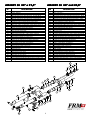
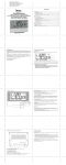
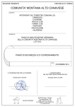
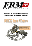
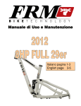
Manuale di Uso e Manutenzione
Owner’s Manual
Italiano pagina 11-4
English pages 44- 7
Congratulazioni per aver scelto la AirAir-Way 32
E’ una forcella estremamente sofisticata che richiede cura ed attenzione.
E’ necessario leggere questo manuale prima di usarla
SSV (Speed Sensitive Valve)
La valvola SSV svolge due principi fondamentali allo stesso tempo: nel primo caso varia la portata del flusso dell’olio in fase di compressione, in modo da ottimizzare
l’assorbimento della forcella a seconda delle necessità. Una velocità di assorbimento massima in caso di urti violenti e velocità progressivamente inferiori in caso di urti meno
violenti. Nel secondo caso funge da valvola di apertura per lo stacco della forcella. Per rendere meglio l’idea, la valvola SSV offre lo stesso funzionamento degli ammortizzatori
avanzati di tipo Stable Platform. Può cioè definire il punto di stacco della forcella in modo da poterlo modificare in baso al peso del ciclista, in modo tale da impedire che la
forcella parta sotto l’influsso della pedalata, ma sia però attiva quando un carico appena superiore la faccia aprire. Il punto di stacco può essere variato molto facilmente con un
pomello esterno, a seconda se il biker desideri che la forcella parta a carichi maggiori o minori, senza peraltro interferire in alcun modo sulle pressione. In altre parole si può
settare la forcella a bassa pressione in modo che una volta che la valvola sia aperta la funzione di assorbimento sia svolta al massimo, ma al contempo si può tarare la valvola
SSV in modo che il punto di stacco sia tanto alto da non farla partire sotto l’influsso della pedalata sia a sedere che in piedi
RAKE VARIABILE
La geometria della Air-Way è stata progettata per offrire il Rake Variabile. Questo si ottiene producendo il Rake voluto con la inclinazione del cannotto di sterzo rispetto ai foderi a
livello della testa. Nelle forcelle con forcellini avanzati , il Rake è fisso, ovvero non cambia a forcella estesa o compressa. A differenza delle forcelle a forcellini avanzati, la Air-Way
modifica quindi il Trail a terra durante la compressione, allo scopo di mantenere la manovrabilità più o meno immutata nelle varie fasi di affondamento. Nelle forcelle a forcellini
avanzati il Trail (Avanzamento)cala drasticamente mentre la forcella si comprime, rendendo il controllo della bici più difficoltoso. Oltre a questo la Air-Way ha un angolo di
incidenza rispetto al terreno di 5° maggiore rispetto a quello delle forcelle a forcellini avanzati. In questo modo gli urti con una componente frontale possono essere assorbiti con
più facilità, mentre le forze verticali (massa del ciclista che pedala sui pedali) non influenzano l’attività della forcella
BLOCCO AUTOMATICO
LA AIR-WAY NON RICHIEDE ALCUN TIPO DI BLOCCO MANUALE. Al ciclista non viene richiesto di bloccare la forcella in salita per poi sbloccarla in discesa, perché la forcella non
viene attivata dagli impulsi sul manubrio, ma solo da quelli che riceve la ruota. In salita la forcella non beccheggia in pedalata, ma assorbe quegli ostacoli che una forcella
bloccata manualmente non è in condizione di assorbire. Invece di perdere tempo a bloccare e sbloccare la forcella, si ha il tempo di bere di più e questo si che è un beneficio per
le prestazioni ! A questo bisogna aggiungere il fatto che la Air-Way non è soggetta al sag iniziale a causa del peso del ciclista per cui la sua corsa è utilizzabile integralmente. La
sua corsa è tutta disponibile, mentre 10-15mm di corsa vengono normalmente utilizzati per il sag necessario su molte altre forcelle.
COSTRUZIONE
E’ una forcella da X-Country - Marathon in cui l’elemento elastico è l’aria compressa e l’idraulica è del tipo a bagno d’olio aperto (le boccole di scorrimento sono immerse
nell’olio). I pezzi sono tutti ricavati col sistema CNC dal pieno e i materiali di elezione sono l’alluminio 7075-T6 (Ergal) e il Carbonio. La testa è ricavata in un unico pezzo con una
struttura tubolare. Le due ali sono infatti alleggerite all’interno con fori che collegano il cannotto agli steli. Il cannotto di sterzo è in Ergal è pressato ed incollato nella testa con una
battuta inferiore per impedire che possa sfilarsi. I due steli sono in Scandium con un diametro di 32mm. Sono inseriti a pressione nella testa ed uno scalino nella parte superiore
della testa impedisce che possano muoversi dalla loro posizione. Sono anodizzati duri con una superficie lucidata a mano che porta la rugosità a livelli intorno a 0,5 Ra e quindi
teflonati per un ottimale scorrevolezza. Una pompa dotata di manometro e di bocchettone per valvole Shraeder è sufficiente per aumentare la pressione dell’aria all’interno dei due
steli, in modo da calibrare esattamente il carico richiesto per il peso del ciclista. Una molla negativa aiuta la forcella a partire nella sua fase iniziale e funge da tampone di fine
corsa estensione, permettendo anche qualche millimetro di lavoro in negativo
IDRAULICA
La parte idraulica si trova all’interno dei due foderi. L’olio riempie i foderi, lubrificando le boccole di scorrimento. In fase di compressione l’olio passa attraverso la valvola SSV,
che viene aperta dalla pressione dell’olio, travasando dalla camera inferiore a quella superiore della forcella. In questa fase la camera d’aria che rimane tra il livello massimo
dell’olio ed il tappo di chiusura diminuisce, con la conseguente compressione dell’aria. L’aria così compressa offre un funzionamento progressivo, ovvero tale da rendere la
forcella sempre più resistente alla compressione, per evitare facili fondocorsa. E’ evidente che il volume della camera d’aria, ovvero il livello dell’olio all’interno della forcella,
determina la progressività nella seconda metà della corsa. In estensione la valvola SSV si chiude ed il travaso dell’olio avviene attraverso un tubo che bypassa la valvola. Un foro,
il cui diametro viene variato da una vite posta esternamente nella parte bassa del fodero sinistro, determina la portata dell’olio in ritorno e quindi il suo damping. Avvitando la vite
si rallenta la sua velocità di ritorno.
Le tarature della Air-Way riguardano:
a) la pressione dell’aria, determinata dal peso del ciclista. A pesi maggiori corrispondono maggiori pressioni di gonfiaggio
b) Il punto di stacco, definito dalla taratura della valvola SSV, modificabile con un rotore esterno
c) la progressione, determinata da livello dell’olio all’interno delle canne
d) la velocità di ritorno, determinata dalla portata dell’apposito foro del circuito idraulico. La sua portata è variabile esternamente
STERZO
La Air-Way 32 è compatibile solo con sterzi da 1,5” conico. Ingrassare la base del cannotto di sterzo ed inserire la pista inferiore dello sterzo. Montare lo sterzo sul telaio ed
infilare il cannotto all’interno dello sterzo. Inserire alcuni anelli distanziali tra sterzo ed attacco manubrio. Infilare l’attacco manubrio nel cannotto di sterzo e segnare con un
pennarello il punto in cui il cannotto fuoriesce dall'attacco manubrio. Smontare la forcella e tagliare il cannotto 2-3mm sotto il segno del pennarello. Rimontare il tutto dopo aver
ingrassato il movimento di sterzo. Registrare il gioco seguendo le istruzioni del produttore. Nel caso dobbiate variare l’altezza dell’attacco manubrio spostate da sotto a sopra
l’attacco manubrio gli anelli distanziale e tagliate il cannotto solo quando sarete certi della posizione
ATTACCO MANUBRIO
Utilizzare attacchi manubrio di buona qualità da 1 1/8” (foro da 28,6mm)
MOZZO RUOTA
La Air-Way 32 è compatibile unicamente con ruote ad asse passante QR15
FRENI
La Air-Way 32 è compatibile unicamente con pinze tipo Post-Mount
SCONSIGLIATA A CICLISTI OLTRE I 95 Kg DI PESO
-1-
paraolio. Sfilare il fodero dallo stelo. Ripetere l’operazione per l’altro paraolio
ATTREZZI PER MANUTENZIONE
3. MODELLO SUPER RACE
• Svitare gli Anelli Chiusura Paraolio (8) con chiave a becchi a 90°
• Bloccare in morsa in qualche modo ambedue i forcellini. Suggeriamo di
acquistare il nostro Thru-Axle Rack, supporto per trasportare le bici con
forcelle QR15 e QR20 sulle barre da tetto.
• Colpire la parte bassa della testa con un martello in gomma per estrarre i
paraolio. Sfilare il blocco foderi/archetto dagli steli
Pinza a becchi a 90° o chiave a molla tipo Park Tool / Cobra
Chiave a brugola 6mm lunga almeno 150mm
Chiave Torx 25
Utensile Inserimento Paraolio OST32 per canne da 32
Olio forcella. Preferibilmente Motul Fork Oil Factory Line. Light
Olio al Teflon
Sigillante Idraulico
Contenitore per olio esausto
Siringa con tubino in plastica
Calibro o metro metallico
Pompa forcelle
4. Con la chiave a becchi svitare la Valvola Olio (18) e la Valvola SSV (20)
5. Sfilare il Gruppo Asta/Pistone (17) dallo stelo sinistro assieme a molla (15),
Limitatore di Corsa (16) e Anello di Tenuta FG (14)
6. Sfilare nell’ordine: le Boccole Guida (12), il loro Distanziale (13), le Rondelle
Estrazione Paraolio (11), i Paraolio (10), l’Anello Chiusura Paraolio (8) con il
Parapolvere incluso (9)
SOSTITUZIONE OLIO
7. Non dovrebbe mai essere necessario separare le singole parti delle Valvole
Olio e SSV. In caso di necessità è preferibile sostituirle con altre nuove
La Air-Way 32 richiede il primo cambio dell’olio dopo 10 ore di
utilizzo. Successivamente ogni 200 ore.
8. Pulire tutto accuratamente, sostituire paraolio e parapolvere e rimontare il tutto
seguendo le istruzioni del prossimo capitolo
1. Smontare la forcella dalla bici. Lavare e pulire accuratamente la forcella
In caso di steli rovinati occorre sostituire l’intero complesso testa (1)
2. Svitare i Tappi Valvola Aria (6a-7a) ed eliminare la pressione interna
premendo sulla estermità degli Spilli delle Valvole Aria (6b). Svitare
completamente il Rotore “Gate” (7b), sia per contare i giri al quale è stato
settato, che per facilitare la fase di rimontaggio. Sollevare il rotore e svitare i
due Tappi Portavalvola Aria (6c e 7e) con la chiave a becchi. Il tappo destro è
dotato di una asta di connessione con la valvola SSV per la sua regolazione
MONTARE LA FORCELLA
Vedi esploso a pagina 4
ATTENZIONE: è bene sostituire i paraolio ogni volta che la forcella viene
smontata. Ingrassare i paraolio e i parapolvere con olio al Teflon. Non utilizzare
grasso al Litio in questa fase
3. ATTENZIONE Comprimere la forcella a fondo corsa e misurare con un calibro
od un metro metallico la profondità dell’olio dal bordo della testa forcella per
ripetere o eventualmente modificarne l’altezza nel momento in cui la forcella
verrà rimontata. Il livello standard è di 90mm
1. Inserire sulla estremità dello stelo l’apposito attrezzo OST32 per la più facile
e sicura inserzione dei paraolio. In sua assenza proteggere il bordo dello
stelo con Domopack per non rovinare il paraolio o il parapolvere.
4. Rovesciare la forcella scolando l’olio dentro un contenitore. Pompare
ripetutamente per cercare di eliminare tutto l’olio all’interno della forcella.
Volendo essere certi di eliminare tutto l’olio, anche se non strettamente
necessario, occorre estrarre il Gruppo Asta/Pistone (17) all’interno dello stelo
sinistro con la chiave a brugola lunga da 6mm. Dopo averlo svitato
completamente, estrarlo battendo la forcella rovesciata sul banco ed
aiutandosi con una pinza da seeger. Pompare per eliminare tutto l’olio, dopo
di che riavvitarlo in posizione
2. Infilare sui due steli nell’ordine: l’Anello Chiusura Paraolio (8) con il
Parapolvere (9) incluso, il Paraolio (10), la Rondella Estrazione Paraolio
(11), la Boccola Guida superiore (12) con il bordo arrotondato rivolto verso
il basso, il Distanziale Boccole Guida (13) e la Boccola Guida inferiore (12)
con il bordo arrotondato rivolto verso il basso
3. Accertarsi che Limitatore di Corsa (16), Molla Negativa (15) e Pistone siano
incastrati assieme in un unico blocco. Il limitatore di Corsa è presente solo
nel caso di corsa 85mm
5. Comprimere la forcella completamente a fondo corsa e versare olio nuovo
all’interno di ogni fodero fino a poco sotto il bordo testa. Tappare i fori degli
steli con carta o uno straccio per evitare che l’olio spruzzi fuori. Estendere e
comprimere la forcella almeno 10 volte per riempire tutte le camere interne.
4. Inserire l’Anello Tenuta FG (14) sulla sede del pistone e infilare il
Complessivo Pistone/Asta (17) nello stelo SINISTRO dal foro inferiore
5. Infilare la Valvola Olio (18) lungo l’ Asta del Pistone sinistro. Avvitarla con
una pinza a becchi bagnando il filetto con sigillante idraulico per evitare che
si possa svitare
6. Spingere la testa completamente a fondo e misurare con un calibro od un
metro la altezza del pelo dell’olio dal bordo stelo. Variarla, aggiungendo o
togliendo olio con siringa o bottiglia in plastica con beccuccio fino a 90mm
dal bordo testa o al livello definito dalla propria taratura (vedi pagina 3).
6. Avvitare la Valvola SSV (20) con una pinza a becchi sullo stelo DESTRO,
bagnando il filetto con sigillante idraulico
7. Avvitare il Tappo Aria (6c) a sinistra ed il Tappo SSV con asta (7e) a destra. In
questo caso occorre essere molto attenti a inserire l’asta in modo che si
connetta con la vite esagonale sul fondo. Procedere con pazienza e cautela.
Serrare con moderazione
8. Rimontare il Rotore Comando Valvola SSV e avvitarlo dello stesso numero di
giri riscontrati al punto 2
9. Gonfiare alla pressione corretta per la vostra taratura e avvitare i Tappi Valvola
Aria (6b)
7. Accertarsi che sul fondo dei foderi ci siano i due O-Ring di Fine Corsa
Compressione (19)
8. Infilare gli steli entro i foderi, orientando nella maniera corretta la testa
9. Spingere le Boccole Guida (12) e loro Distanziale (13) entro i foderi,
premendole con le mani appoggiandoci sopra la Rondella Estrazione
Paraolio (11)
10. Inserire i Paraolio (10) nelle loro sedi
SMONTARE LA FORCELLA
Vedi esploso a pagina 4
11. Versare gocce di Olio al Teflon sulla la parte degli steli appena sopra il
paraolio. Questo lubrificante rimarrà imprigionato tra i Paraolio ed i
soprastanti Parapolvere inseriti nei Tappi Paraolio (8)
1. Seguire i passaggi da 1 a 4 del capitolo precedente, estraendo anche il
Gruppo Asta/Pistone (17)
12. Avvitare i Tappi Paraolio (8) stringendolo con la pinza a becchi
2.
•
•
•
13. Comprimere la forcella e avvitare l’Asta/Pistone all’interno dello stelo sinistro
con la lunga chiave a brugola da 6mm. Serrare moderatamente
MODELLO XC TEAM:
Smontare l’archetto (2) con la chiave Torx 25
Svitare gli Anelli Chiusura Paraolio (8) con chiave a becchi a 90°
Bloccare nella morsa (con morsetti in alluminio) uno dei due forcellini ruota e
colpire la parte bassa della testa con un martello in gomma per estrarre il
14. Rimontare l’Archetto incastrandolo nelle sedi dei foderi. Bagnare di
frenafiletti medio le viti a brugola (3) ed avvitarle a 5Nm con chiave Torx 25
15. Seguire ora i punti 5 - 6 - 7 – 8 - 9 della sezione “SOSTITUZIONE OLIO”
2
Comando Valvola SSV. E’ invece da evitare l’aumento della pressione dell’aria.
Avvitandolo si aumenta il Punto di Stacco. La vite di registrazione ruota per 10
giri completi. Consigliamo di fare variazioni di non più di un paio di giri della vite
e provare nuovamente la bici fino a che la forcella non si muova mentre si pedala
sui pedali, ma una qualsiasi variazione del terreno possa però essere assorbita.
Trovata la taratura è consigliabile contare il numero dei giri della vite per poter
ripetere la taratura in futuro
MANUTENZIONE ORDINARIA
• Ogni 10 uscite sgonfiare la forcella dall’aria, svitare gli Anelli Chiusura
Paraolio, pulire e riempire la camera tra Paraolio e Parapolvere con olio al
Teflon. La scorrevolezza rimane ottimale
• Sostituire l’olio almeno una volta all’anno o ogni 200 ore di funzionamento
3) Progressione
TARARE LA FORCELLA
Affrontate un percorso conosciuto nel quale la discesa sia abbastanza
impegnativa da richiedere l’uso di tutta la corsa della forcella. L’escursione deve
essere utilizzata totalmente, senza giungere con troppa frequenza a fondo corsa.
PROCEDURA RAPIDA DI SETTAGGIO
a. Svitare completamente il Rotore Valvola SSV in modo da non avere alcun
effetto di “Gate” o Stable Platform che dir si voglia
b. Svitare completamente il rotore “Rebound” sul fondo del fodero sinistro in
modo da non avere alcun effetto di smorzamento in ritorno
c. Montati in bici in assetto di pedalata, con un movimento del corpo per
portare peso sul manubrio trovare la pressione che produca circa 20mm
di sag (da 1,5 a 2,5 bar a seconda del peso. Vedi paragrafo 1)
d. Regolare la velocità di ritorno (Rebound) a seconda delle vostre esigenze
(vedi paragrafo 4)
e. Avvitare il Rotore Comando Valvola SSV di 3 o 4 dei 10 giri disponibili.
f. Provare sul campo questo settaggio, avvitando o svitando il Rotore
Comando Valvola SSV fino ad ottenere il punto di stacco desiderato
g. Quando sarete a vostro agio con questa taratura iniziale sarà possibile
raffinarla ulteriormente modificando la Progressione. In questo caso
leggete il paragrafo 3
1 Nel caso in cui non si riesca ad utilizzare tutta o quasi tutta la corsa, la forcella
è troppo progressiva per le vostre caratteristiche. La camera dell’aria sopra
l’olio è troppo piccola e quindi va tolto olio per aumentarla.
2 Nel caso contrario in cui ci si trovi troppo spesso a fondo corsa, la forcella è
troppo poco progressiva per le vostre caratteristiche. La camera dell’aria
sopra l’olio è troppo grande e quindi va aumentato il livello dell’olio per
diminuirla
Nella forcella di serie il livello dell’olio è a 90mm dal bordo testa con la forcella
completamente compressa. Apportate variazioni di non oltre 5mm per volta
curando che l’olio sia allo steso livello in ambedue gli steli. Pressione dell’aria e
altezza dell’olio sono strettamente correlate:
a. La pressione dell’aria controlla la resistenza della forcella alla compressione.
Maggiore è la pressione, maggiore sarà la resistenza alla compressione
b. Il livello dell’olio controlla la Progressione, ovvero la differenza di resistenza
alla compressione che si sviluppa tra l’inizio e la fine della corsa. Maggiore è il
livello dell’olio, maggiore sarà il livello di progressività, ovvero la difficoltà a
raggiungere il fine corsa, a parità di durezza iniziale.
GLOSSARIO
L’equilibrio tra le 3 variabili:
a) Pressione dell’Aria
b) Taratura della Valvola SSV
c) Altezza della Camera dell’Aria
porta alla taratura ideale.
Occorre lavorare sulle tre variabili per ottenere il risultato migliore.
1) Pressione dell’aria
Normalmente una forcella dovrebbe comprimersi di circa 1/4-1/5 della sua corsa
col peso del ciclista. Con la Air-Way 32 difficilmente si presenta un qualsiasi tipo
di sag, per cui la pressione va regolata inizialmente seguendo i dati forniti dalla
seguente tabella:
4) Rebound
Pressione consigliata:
Peso ciclista
Sotto I 60 kg
Da 60 kg a 75 kg :
Da 75 kg ad 90 kg:
Il termine Rebound identifica la Velocità di Ritorno
In questa fase è determinate la sensibilità del pilota, per capire se la forcella
rimbalza perchè troppo veloce o se non ritorna abbastanza velocemente per
assorbire urti di frequenza elevata. Per variarla occorre agire sul Rotore che
appare sul fondo del fodero sinistro. Avvitandolo si riduce il passaggio dell’olio in
fase di estensione e la forcella rallenta la sua velocità. Svitandolo, il passaggio
olio aumenta, così come la sua velocità di estensione. Trovata la giusta
regolazione è bene avvitare il Rotore fino al suo blocco, contando
contemporaneamente di quanti giri viene avvitata ed annotarli
Bar
1,6 - 1,8
1,9 - 2,2
2,3 – 2,6
La pressione deve essere la medesima nei due foderi.
2) Valvola SSV
La valvola SSV deve essere tarata in modo che la forcella non si muova sotto
l’impulso della pedalata. Mentre si pedala sarà evidente se la forcella inizia a
ondeggiare nei momenti di transizione da seduti a in piedi sui pedali. Se questo
avviene è necessario alzare la soglia di stacco iniziale, agendo sul Rotore
5) Modificare la corsa
La corsa della forcella può essere trasformata da 85 a 100mm eliminando il
Limitatore di Corsa (16). Seguire le Istruzioni della Pagina 2
Via Mattei 18/a 48025
Riolo Terme (Ra) ITALY
Phone +39 0546 70310 fax 74623
E-mail pubblico: [email protected]
Ordini Italia: [email protected]
e-commerce from the home page of www.frmbike.com
3
AIRAIR-WAY 32 29” e 27,5”
AIRAIR-WAY 32 29” and 27,5”
Nr
N°
DESCRIZIONE
1
2
3
4
4
5
5
6
6a
6b
6c
7
7a
7b
7c
7d
7e
8
9
10
11
12
13
14
15
16
17
18
19
20
21
22
OST32
Testa completa. Canne da 32mm. Sterzo 1,5” conico
Archetto / Alluminio
Viti fissaggio archetto / Brugola M5x12 mm / Titanio
Fodero DX carbonio per canne 32mm 29”. Forcellini QR15
Fodero DX carbonio per canne 32mm 27,5”. Forcellini QR15
Fodero SX carbonio per canne 32mm 29”. Forcellini QR15
Fodero SX carbonio per canne 32mm 27,5”. Forcellini QR15
Complessivo Tappo e Valvola Aria per canne 32mm
Tappo Valvola Aria + O-Ring 2056 (14x1,78mm) Come 7a
Valvola Aria + Spillo + O-Ring 2021 (5,28x1,78mm) Come 7d
Tappo Portavalvola Aria + O-Ring 2106 (26,70x1,78mm)
Completo Comando Valvola SSV e Rotore
Tappo Valvola Aria + O-Ring 2056 (14x1,78mm) Come 6a
Rotore Comando Valvola SSV
O-Ring 22x1mm
Valvola Aria & O-Ring 2021 (5,28x1,78mm). Come 6b
Tappo Portavalvola Aria & O-Ring 2106 con asta comando SSV
Anello Chiusura Paraolio per canne 32mm
Parapolvere SA 32
Paraolio TTO TC 32x42x7mm con labbro parapolvere
Rondella Estrazione Paraolio / Alluminio per canne 32mm
Boccola Guida Iglodur W300 36x32x20mm
Distanziale Boccole Guida / alluminio
Anello Tenuta FG 15049 4,9x1,5 mm
Molla Negativa (Dia. 18,4mm Lunghezza 25mm)
Limitatore di Corsa
Gruppo Asta/Pistone per canne 32mm. Lunghezza 140mm
Valvola Olio per canne 32mm
Fine Corsa Compressione/ O-Ring (13,8x5,35 mm)
Valvola SSV per canne 32mm
Assale QR15 (M12x1,5mm) Anodizzato Duro
Boccola sostituibile assale QR15 (M12x1,5mm) Anodizz. Dura
Utensile inserimento Paraoli per canne da 32mm
DESCRIPTION
1
Crown Assembly: Upper tubes 32mm. 1,5” taper steerer t.
2ReveBrace / Light Alloy
3
Brace Fixing Bolt / Allen M5x12 mm / Titanium
4
Right Lower Leg for 32mm stanchions 29”/ Carbon F. QR15
4
Right Lower Leg for 32mm stanch. 27,5”/ Carbon F. QR15
5
Left Lower Leg for 32mm stanchions 29”/ Carbon F. QR15
5
Left Lower Leg for 32mm stanchions 27,5”/ Carbon F. QR15
6
Air Valve Assembly for 32mm stanchions
6a
Air Valve Cap + O-Ring 2056 (14x1,78mm) Same as 7a
6b
Air Valve+Needle+O-Ring 2021 (5,28x1,78mm) Same as 7d
6c
Cap Holder of Air Valve + O-Ring 2106 (26,70x1,78mm)
7
Air Valve Assembly with SSV Actuator
7a
Air Valve Cap + O-Ring 2056 (14x1,78mm) Same as 6a
7b
SSV Valve Knob
7c
O-Ring 22x1mm
7d
Air Valve+needle+O-Ring 2021 (5,28x1,78mm) Same as 6b
7e
Actuator of SSV Valve with axle
8
Oil Seal Lock Ring for 32mm stanchions / Light Alloy
9
Dust Seal SA32
10
Oil Seal TTO TC 32x42x7mm with dust seal
11
Shim for 32mm upper tubes / Light Alloy
12
Bushing / Iglodur W300 36x32x20mm
13
Bushing Spacer / Light Alloy
14
Piston Seal FG 15049 4,9x1,5 mm
15
Top Out Spring Assembly ( Dia. 18,4mm Length 25mm )
16
Travel Limitator
17
Piston/Shaft Assembly for 32mm stanchions. 140mm long
18
Oil Valve Assembly for 32mm stanchions
19
Bottom-Out Damper / O-Ring (13,8x5,35mm)
20
SSV Valve Assembly for 32mm stanchions
21
QR15 Axle (M12x 1,5mm) Hard Anodised
20
Replaceable QR15 Nut (M12 x 1,5mm) Hard Anodised
OST32 Seal Tool for 32mm stanchions
7
d
c
e
1
10
12
11
20
c
b
19
13
9
12
4
5
18 17
21
3
22
16
2
4
15
14
8
6
a
b
a
Thank you for making FRM your choice in front suspension.
The AirAir-Way 32 is a highly technical product which requires your maximum attention and care
SSV (Speed Sensitive Valve)
The SSV valve has two main contemporary functions: Firstly it varies the flow of oil during the compression phase of the fork so that the absorption of the fork is optimised in
every situation. The valve has been tweaked to flow much more fluid at high shaft speed. This makes the fork respond noticeably better over sharp impacts, while progressively
smaller oil ports are used to absorb impacts of less-violent nature. Secondly the valve tunes the lockout threshold. This means that the SSV valve can be tuned in order to modify
the pedalling platform, depending on the weight of the rider, this way avoiding fork compression when out of the saddle, but leaving it active when a bit more force opens the
valve stack. The threshold may be varied depending on the rider preferences and enables riders to adjust the platform from almost nothing to nearly locked out. In other words,
the fork can be set at such a low pressure that a downward pedal thrust won’t unseat the SSV valve, but a tiny whack on the front tyre will open the valve and free the fork to
smooth out the trail. The fork features enough anti-bob effect to allow the rider to break out of the saddle without thinking about what the front of the bike is doing. One additional
feature worth mentioning is that the air volume has been increased so the air spring chamber allows for a less progressive curve.
VARIABLE TRAIL
The Air-Way geometry allows Variable Trail. This special feature enables the fork to progressively modify its trail during the compression phase, thus maintaining handling
consistency during compression.
AUTOMATIC LOCKLOCK-OUT
The rider is not required to manually lock-out the fork when riding uphill to then unblock it when downhilling, because the fork is not activated by vertical forces on the handlebar
but only by impacts to the wheels. When riding up-hill the fork does not bob, but absorbs the small impacts that a manually locked fork is not able to absorb. Instead of loosing
time locking and unlocking the fork the rider will have time to drink more, which is always a large benefit for performance! It is worth mentioning that the Air-Way does not sag
under the weight of the cyclist and so the wheel travel is completely available. The full travel is always available whereas, in many other forks, 10-15mm are used by
sagging.
CONSTRUCTION
This is a fork with similar function to that of a motorcycle’s telescopic fork. It is air sprung, and features an oil-bath type hydraulics system (with bushings immersed in oil). The
components are all CNC machined from solid 7075-T6 Aluminium. The crown is cut from a single block of tubular section, while the two wings are lightened internally by holes
connecting the steer tube to the upper tubes. The 1,5” tapered steerer tube is press-fitted into the crown with a lower lip to keep it from sliding out. The two upper tubes of 32mm
of diameter are in Scandium alloy. They are press-fitted into the crown, and a lip in the upper part of the crown keeps them locked in position. The upper tubes are hard-anodized,
with hand polished surfaces of 0.5 Ra smoothness, and then Teflon-coated for optimum fluidity of motion. The lower tubes are in carbon fibre. A Shraeder-valved pump with a
pressure gauge is required to increase the air pressure inside the two upper tubes. This calibrates the exact air spring required for the individual cyclist's weight.
HYDRAULICS
The hydraulic components are located inside the left lower leg. The hydraulic oil fills the sleeves, lubricating the bushings and all internal parts. In the compression phase the oil
flows through the SSV (Speed Sensitive Valve) valve which is opened by the pressure of the oil transferring from the lower to the upper chambers of the fork. In this way, the airspace between the maximum level of the oil and the sealing cap diminishes, resulting in compression of the air. The air, thusly compressed, offers progressive compression
resistance, and largely prevents bottoming out of the fork. Obviously, the volume of the air-space, and therefore the oil level inside the fork, determines the progressiveness of the
second half of the cycle. While extending, the SSV valve shuts-off, and oil flows through a port in the Piston Shaft. Rebound damping can be modified (by varying the size of the
port) with an external knob located on the flat surface of the lower left leg. Turning the knob clockwise will slow down the rebound damping. The rebound will become faster if the
knob is turned counter-clockwise.
The Air-Way fork can be tuned though the following steps:
1. Air pressure is defined by the cyclist’s weight. The higher the weight, the higher the air pressure. Stiction, which is usually quite high with air sprung forks, is countered by a
steel negative coil-spring, which helps the fork to react to smaller impacts
2. The threshold, defined by the setting of the SSV valve, is modified through an external knob
3. Progressiveness is determined by the oil level, and therefore the air chamber. Changing the oil level will modify the progressive resistance
4. Rebound damping is determined by the diameter of a hole in the rebound hydraulic circuit. This oil port can be varied through the external adjustment knob
HEADSET
Air-Way 32 forks are compatible with 1,5” taper headsets only. Refer to the specific headset manual when assembling onto the frame and fork
STEM
Use a good quality 1 1/8” (28,6mm bore) stem
MOZZO RUOTA
Air-Way 32 forks are compatible with QR15 wheels only
BRAKES
Air-Way 32 forks are compatible with Post-Mount type disc brakes
WARNING
Never remove, or have the steer tube removed from the crown. The steer tube is press fit assembled in the factory. Pressing the steer tube out will permanently damage the
crown beyond repair and render it unsafe for use.
Any other alteration or modification to your fork will probably be unsafe. Contact your FRM distributor for safety information prior to modifying your fork in any way.
Do not use the FRM fork if any parts are broken, bent, cracked or damaged. Contact your FRM distributor if you have any questions concerning the integrity of your fork.
FRM recommends that you periodically inspect your fork for wear or damage. Inspect the crown, inner legs and outer leg dropout areas for cracks or damage. Before every
ride check the air pressure and that the positive rebound stop is properly functioning to ensure that the fork does not over-extend.
Check the clearance between the down tube of the bike and the fork air valve caps. If possible, adjust the handlebar height so that the handlebar will not hit the top tube of the
bike.
Always use genuine FRM replacement parts. Use of aftermarket replacement parts voids the warranty and could cause structural failure to the fork. Structural failure may result
in loss of control of the bicycle with possible serious and/or fatal injuries
CYCLISTS EXCEEDING 90 kg SHOULD NOT RIDE THIS FORK
5
• Unscrew the Seal Lock Rings (8) with 90° small tip pliers.
• Clamp both dropouts in a vice with soft grips. It is suggestible to purchase
the FRM Thru-Axle Rack for this purpose. Tap the lower part of the crown
with a plastic mallet until the Oil Seal (9) pops out from its’ seat.
TOOLS FOR MAINTENANCE
90° small tip pliers
6mm hex wrench long extension
Torx 25 key
OST32 Seal Tool for 32mm stanchions
Fork Oil. Preferably Motul Fork Oil Factory Line. Light
Teflon Oil
Hydraulic Sealant
Syringe with plastic pipe
Oil drain pan
Caliper or a metal ruler
Fork pump
5. Remove the Oil Valve (18) and the SSV Valve (20) from the bottom of the
upper tubes with the 90° pliers.
6. Slide the Piston/Shaft Assembly (17) with Spring (15), Travel Limitator
(16) and Piston Seal FG (14) out of the stanchion.
7. Slide the Lower Bushings (12), their Spacer (13), the Aluminium Shims
(11), the Oil Seals (10), the Seal Lock-rings (8) with the Dust Seal (9) off
the stanchion.
8. Oil Valve and SSV Valve should not be disassembled. In case of necessity
purchase a new assembly.
9. Clean the stanchions and inspect for wear and/or damage (nicks,
scratches or dents).
OIL REPLACEMENT
In case of damage the complete Crown Assembly (1) must be replaced
This fork needs an oil replacement after 10 hours of riding. Regular
maintenance requires oil replacements every year, or 200h of riding
FORK REASSEMBLY
1. Remove the fork from bicycle. Clean dirt and dust from the fork.
See schematic on page 4
2. Unscrew the Air Valve Caps (6a-7a). Deflate the fork by pressing the Air Valve
Needles. Unscrew the SSV Valve Knob (7b) in order to know the number of turns
the fork was set, as well as to facilitate the phase of reassembling. Lift the Knob
and unscrew the Air Valve Assemblies (6c - 7e) from the top of the legs with 90°
pliers. The right side Air-Valve Assembly (7e) is fitted with a long axle
connecting the Knob to the SSV Valve for its’ setting.
ATTENTION: replacement of the Oil Seals is recommended every time the fork
is disassembled. Wipe the inner lips of the oil seal and dust seals with Teflon
oil before sliding them onto the upper tube
3. ATTENTION Compress the fork completely and measure the oil depth from the
top of fork legs with a caliper or metal rule. It is necessary to know this value
when reassembling the fork. The stock level is 90mm.
4. Drain the oil by turning the fork upside down. Clean the inside by refilling with
clean oil and pushing the stanchions in and out several times. Drain the oil again.
Repeat the process until the inside of the fork is clean
5. With the fork fully compressed fill each stanchion with new fork oil. Plug the
stanchion holes with paper or a rag and pump the fork up and down several
times, allowing the oil to fill up all internal cavities. Add oil as necessary until the
fork is full.
6. Very slowly compress the fork until it bottoms out, and measure oil depth with a
caliper or metal rule. Add or remove oil with a syringe with a plastic pipe until it
matches the depth of 90mm, or the depth you found better for your weight and
ride characteristics.
7. Install the Air Valve Assembly (6c) onto the left side stanchion and the SSV Valve
Actuator (7e) using light pressure. In this last case pay attention that the tube
connects to the hexagonal screw of the SSV Valve. Do it with patience and
caution.
1. Slide the Seal Tool OST32 into the lower leg end for an easier and safer
installation of the Oil Seal. In case you do not have this tool protect the
tube edge with soft tape or cling film not to damage the seal lips when
sliding the seals onto the tube edge.
2. Slide the Seal Lock-rings (8) with Dust Seals, the Oil Seals (10), the
Aluminium Shims (11), the Upper Bushings (12) with their rounded edge
facing downwards, the Bushing Spacer (13) and the Lower Bushings
(12) with their rounded edge facing downwards onto both lower legs.
3. Check that the Top-out Spring (15), the Travel Limitator (16) and the
Piston are locked together in one assembly. The Travel Limitator used
only with 85mm fork travel.
4. Wrap the Piston Seal FG (14) around the piston groove and slide the
Piston/Shaft Assembly (17) into the LEFT stanchion from its’ lower end.
5. Slide the Oil Valve (18) along the Piston Shaft. Put some drops of
Hydraulic Sealant on the threads. Tighten it with the 90° pliers.
6. Install the SSV Valve (20) onto the lower end of the RIGHT upper tube.
Put some drops of Hydraulic Sealant on the threads. Tighten it with the
90° pliers.
7. Check for the presence of the bottom out dampers (19) at the bottom of
the lower legs.
8. Reinstall the SSV Valve Knob (7b) and turn the same number of turns of point 2.
9. Inflate the Air Valves with the fork pump at the pressure level suggested for your
weight and/or ride characteristics and reinstall both Air Valve Caps.
8. Slide the Crown/Upper Tube Assembly into one Lower Leg. Check that
the crown rear side faces the fork Brace.
FORK DISASSEMBLY
10. Slide the Oil Seals (10) along the upper tubes into their seats. Gently hand
push the seals so that they insert deeper into their seat.
See schematic on page 4
9. Push Bushings (12), Spacers (13) and Aluminium Shims (11) into their
seats in the lower leg. The shim has to properly bottom into the seal seat.
1. Follow the instructions of “Oil Replacement” from point 1 to point 4.
11. Pour some Teflon Oil over the seal surface. This lubricant will be trapped
between Oil Seals and Dust Seals maintaining them well lubricated.
2. Unscrew the Piston/Shaft Assembly (17) of left leg with a long 6mm hex
wrench.
12. Install in the Seal Lock-ring (8) with the 90° pliers.
3. MODEL XC TEAM:
• Disassemble the Fork Brace (2) with a Torx 25 key.
13. Compress the fork and fix the Piston/Shaft Assembly (17) into the left
upper tube with the 6mm hex long wrench. Hand tighten.
14. Assemble the Fork Brace (2) with a Torx 25 key applying a drop of Loctite
Medium Locking Compound on the Titanium bolts.
• Unscrew the Seal Lock Rings (8) with 90° small tip pliers.
• Clamp one dropout in a vice with soft grips. Tap the lower part of the crown with
a plastic mallet until the Oil Seal (9) pops out from its’ seat.
4. MODEL SUPER RACE
6
15. With the fork fully compressed fill each stanchion with Motul Fork Oil
Factory Line. Plug the stanchion holes with paper or a rag and pump the
fork up and down several times, allowing the oil to fill up all internal
cavities.
16. Follow points 5-6-7-8-9 of the section “OIL REPLACEMENT”.
must be raised. Turn the SSV Valve Knob a few turns clockwise to modify the
spring preload of the valve. The knob rotates 10 complete turns. Ride and
adjust again until the fork does not bob when out of the saddle, but the valve
opens as soon as the front wheel hits the smallest of the bumps and the bike
floats over the obstacles. Once the correct setting has been found we
recommend that you count the number of turns of the bolt to be able to repeat
this setting in future.
REGULAR MAINTENANCE
• Every ten rides deflate the fork, unscrew the Seal Lock-Ring and lube the lower
side of the Dust Seal with Teflon oil. No stiction will build up in the fork.
• Replace the oil at least once a year or after 200 hours of riding.
3) Tuning the Fork Progressiveness
TUNING THE FORK
FAST SETTING
a. Turn the SSV Valve Knob counter-clockwise in such a way that there is no
“Gate” or “Stable Platform” effect.
b. Turn the Rebound Knob at the bottom of the left leg counter-clockwise, in
such a way that there is no rebound damping effect.
c. Sit on the saddle and, with body movement, put pressure on the handlebar.
The fork should sag about 20mm. Set the fork pressure till you reach this sag
level (from 1,5 to 2,5 bars depending from your body weight. See chapter 1).
d. Set the rebound speed to your preference turning the Rebound Knob (see
chapter 4).
e. Turn SSV Valve Knob clockwise by 3 or 4 of the 10 available turns.
f. Field test this setting whilst turning the SSV Valve Knob clockwise or counterclockwise, till the desired threshold is obtained.
g. After the final setting is done to your requirments, read the chapter 3 in order
to under stand a further way to make your fork work even better in downhill
sections: progressiveness.
GLOSSARY
1) Air Pressure
Most forks are designed to compress (sag) when sitting on the bike. The Air-Way
32 shows almost no sag under the weight of the cyclist. For this reason the
pressure should be set following the Pressure Chart below:
PRESSURE CHART
Cyclist weight
Under 60 kg (132 lb):
60 - 75 kg (132 -165 lb):
75 - 90 kg (165 -198 lb):
Air trapped between a piston and a cylinder makes a lightweight, but not
linear, spring. You can make significant changes to your Air Way’s spring rate
by varying the air volume. Raise the oil level, and you can run lower air
pressure for initial plushness, but the air will be pressurized quickly enough to
prevent bottoming out. If you feel like the spring ramps up too quickly, remove
oil (increasing air volume) therefore allowing the fork to use more of its’ travel
for the given pressure. The right balance combines air pressure and air
volume to find the ride you feel you are after. Ride a familiar route on which
you know that a downhill leg is sufficiently engaging to require full fork
extension. The rule to follow is that the available travel should be used fully,
without bottoming out too often. The fork has a standard oil level of 90mm,
from the rim of the upper tube when the fork is fully compressed. Make
adjustments of not more than 5mm at a time, making sure that the oil is at the
same level in both the upper tubes.
a. The air pressure controls the resistance of the fork to compression. Higher
the pressure, higher the resistance to compression.
b. The oil level controls the progressiveness, that is the difference in the
resistance to compression that develops between the beginning and the
end of the fork travel. The higher the oil level, the higher the
progressiveness, that is, the difficulty in getting full travel, at the same
starting air pressure.
The equilibrium between the three variables:
a) Air Pressure
b) Spring pre-load of the SSV Valve
c) Volume of Air Chamber
results in an ideal setting of the fork. The three variables must be adjusted
until the best result is achieved.
4) Fine tuning of Rebound Damping.
Bar
1,6 – 1,8
1,9 - 2,2
2,3 - 2,6
Air pressure must be set at the same level in both legs. Individual riding preferences
may require different air pressures which can be found when actually riding the
bike. As a general rule, the fork becomes stiffer when you add air pressure, and
softens as you decrease air pressure.
The Air-Way 32 features external adjustable rebound damping. The knob is
located at the bottom of the left leg. To adjust the rebound damping turn the
knob clockwise to slow down the rebound or counter-clockwise to speed up
the rebound. Excessive rebound damping (too slow) will give you a harsh ride
over repetitive bumps, causing the fork to “pack up”. Insufficient rebound
damping (too fast) will make the fork over-active and it will tend to top out.
Once the correct setting has been found we recommend that you count the
number of turns of the bolt to be able to repeat this setting in the future.
5) Modifying the Travel
2) Adjustment of the SSV Valve
The SSV Valve must be set in a way that the fork rides softly but, depending on the
pedalling platform, can deliver bob-free power when standing out of the saddle. Set
the air pressure as explained in point “c” of FAST SETTING and ride the bike. If the
fork starts bobbing when getting out of the saddle, the threshold of the SSV Valve
Fork Travel can be modified from the original 85mm to 100mm by
disassemblying the Travel Limitator (16) from the Piston/Axle Assembly.
Follow the instructions on Page 6.
Via Mattei 18/a
48025 Riolo Terme (Ra) ITALY
Phone +39 0546 70310 fax 74623
General e-mail : [email protected]
Foreign orders: [email protected]
e-commerce from the home page of www.frmbike.com
7