1
Air Handling Units
Unità Trattamento Aria
CONTROL PANEL
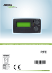
UC 300-M / UC 300-MHE Control panel
Pannello di controllo UC 300-M / UC 300-MHE
INSTALLATION, USE and MAINTENANCE
INSTALLAZIONE, USO e MANUTENZIONE
SAFETY WARNINGS - AVVERTENZE PER LA SICUREZZA
Read this manual carefully before installing and/or using the
equipment and keep it in an accessible place.
This equipment constitutes a component which is part of
complex installations: it is the responsibility of the electrical
installer to draw up the general diagram of the system and
the electrical connections outside the equipment.
The manufacturer’s technical office can be contacted on the
numbers shown on the back of this manual for queries or
special technical requests.
Le g g e re co n at te n z i o n e q u e s to l i b re t to p r i m a
dell’installazione e/o dell’uso dell’apparecchiatura e
conservarlo in un luogo accessibile.
La presente apparecchiatura costituisce un componente che
fa parte di installazioni complesse: è compito dell’impiantista
elettrico redigere lo schema generale dell’impianto e dei
collegamenti elettrici esterni all’apparecchiatura.
L’ufficio tecnico del Costruttore si rende disponibile
ai numeri indicati sul retro del presente libretto per
consulenze o richieste tecniche particolari.
•
CAUTION
Installation and maintenance must only be carried out by
qualified personnel.
The hydraulic and electrical systems and the places where
the equipment is to be installed must comply with the
safety, accident prevention and fire prevention standards
in force in the country of use.
•
ATTENZIONE
L’installazione e la manutenzione vanno eseguiti solo da
personale qualificato.
Gli impianti idraulici, elettrici ed i locali di installazione
delle apparecchiature devono rispondere alle norme di
sicurezza, antinfortunistiche e antincendio in vigore nel
Paese di utilizzo.
• It is essential to connect the equipment to an effective earthing
system and include it in an equipotential system whose
effectiveness shall conform the local regulations.
• E’ indispensabile collegare l’apparecchiatura ad un efficace
impianto di terra e includerla in un sistema equipotenziale
la cui efficacia deve ottemperare alle norme in vigore.
• Before making the electrical connection, ensure that the
voltage and frequency shown on the data plate correspond to
those of the power supply system.
• Prima di eseguire il collegamento elettrico, accertarsi
che la tensione e la frequenza riportate sulla targhetta
caratteristiche corrispondano a quelle dell’impianto
d’alimentazione.
GENERAL WARNINGS - AVVERTENZE GENERALI
• If, after having unpacked the equipment, any anomaly is
noted, do not use the equipment and contact an Assistance
Centre authorised by the manufacturer.
• After installation, dispose of the packaging in accordance with
the provisions of the regulations in force in the country of use.
• Use original spare parts only: disregarding this rule invalidates
the warranty.
• The manufacturer declines all responsibility and considers the
warranty invalid in the following cases:
-The aforementioned warnings and safety regulations,
including those in force in the country of installation, are not
respected.
- The information given in this manual is disregarded.
-
There is damage or injury to people, animals or objects,
resulting from incorrect installation and/or improper use of the
products and equipment..
-Inaccuracies or printing and transcription errors are
contained in this manual.
• The manufacturer also reserves the right to cease production at
any time and to make all the modifications which it considers
useful or necessary without any obligation to give notice.
• Se dopo aver disimballato l’apparecchiatura si nota una
qualsiasi anomalia non utilizzare l’apparecchiatura e
rivolgersi ad un Centro di Assistenza autorizzato dal Costruttore.
• Alla fine dell’installazione smaltire gli imballi secondo quanto
previsto dalle normative in vigore nel Paese di utilizzo.
• Esigere solo ricambi originali: la mancata osservazione di
questa norma fa decadere la garanzia.
• Il Costruttore declina ogni responsabilità nei casi seguenti:
- Non vengano rispettate le avvertenze e le norme di
sicurezza sopra indicate, comprese quelle vigenti nei paesi
di installazione.
- Mancata osservanza delle indicazioni segnalate nel
presente manuale.
- Danni a persone, animali o cose, derivanti da una errata
installazione e/o uso improprio di prodotti e attrezzature.
- Inesattezze o errori di stampa e trascrizione contenuti nel
presente manuale.
• Il Costruttore, inoltre, si riserva il diritto di cessare la
produzione in qualsiasi momento e di apportare tutte le
modifiche che riterrà utili o necessarie senza obbligo di
preavviso.
3
DISPOSAL - SMALTIMENTO
In base a quanto previsto dalle seguenti
direttive europee 2002/95/CE, 2002/96/CE e
2003/108/CE, relative alla riduzione dell’uso
di sostanze pericolose nelle apparecchiature
elettriche ed elettroniche, nonché allo
smaltimento dei rifiuti.
In accordance with the provisions of the following European
directives, 2002/95/EC, 2002/96/EC 2003/108/EC, regarding
reducing the use of hazardous substances in electrical and
electronic equipment, in addition to waste disposal.
The crossed-out rubbish bin symbol shown on the equipment
indicates that, at the end of its useful life, the product must be
collected separately from other waste.
As a result, users shall take the equipment to suitable disposal
centres for electronic and electrotechnical devices. Otherwise, they
can choose to give it back to the seller if they are going to buy a
new equivalent one.
Appropriate separate waste collection for subsequent sending of
the disused equipment for recycling, treatment and compatible
environmental disposal contributes to preventing possible
negative effects on the environment and favours recycling of the
materials of which the equipment is composed.
The abusive disposal of the product by the user leads to the
application of the penalties envisaged by current regulations
regarding the matter.
Il simbolo del cassonetto barrato riportato sull’apparecchiatura
indica che il prodotto alla fine della propria vita utile deve essere
raccolto separatamente dagli altri rifiuti.
L’utente dovrà, pertanto, conferire l’apparecchiatura giunta
a fine vita agli idonei centri di raccolta differenziata dei rifiuti
elettronici ed elettrotecnici, oppure riconsegnarla al rivenditore
al momento dell’acquisto di una nuova apparecchiatura di tipo
equivalente, in ragione di uno a uno.
L’adeguata raccolta differenziata per l’avvio successivo
dell’apparecchiatura dismessa al riciclaggio, al trattamento e allo
smaltimento ambientale compatibile contribuisce ad evitare
possibili effetti negativi sull’ambiente e sulla salute e favorisce
il riciclo dei materiali di cui è composta l’apparecchiatura.
Lo smaltimento abusivo del prodotto da parte dell’utente
comporta l’applicazione delle sanzioni previste dalla vigente
normativa in materia.
4
INDEX
INDICE
Description
Descrizione
SAFETY WARNINGS
AVVERTENZE PER LA SICUREZZA
3
GENERAL WARNINGS
AVVERTENZE GENERALI
3
DISPOSAL
SMALTIMENTO
4
PRELIMINARY OPERATIONS
OPERAZIONI PRELIMINARI
6
DESCRIPTION OF THE EQUIPMENT
DESCRIZIONE APPARECCHIATURA
7
INSTALLATION
INSTALLAZIONE
7
Page
Pag.
Installation of control unit on electric board
Installazione centralina su quadro elettrico
7
Connecting the unit and control board
Collegamento unità e centralina
8
Unit consent
Consensi dell’unità
8
CENTRALINA
11
Display
Display
11
Button description
Descrizione tasti
11
Outlining diagram of the control unit masks
Schema riassuntivo maschere centralina
12
User menu parameters
Parametri menu utente
13
Technical menu parameters
Parametri menu tecnico
13
Setting time slots
Imposta fasce orarie
14
Readouts menu
Menu letture
15
Faults and alarms
Guasti e allarmi
16
Synoptic
Sinottico
17
CONTROL UNIT
5
PRELIMINARY OPERATIONS
OPERAZIONI PRELIMINARI
TESTING, TRANSPORT AND UNPACKAGING
ISPEZIONE, TRASPORTO E DISIMBALLO
Upon receipt, check immediately that the packaging is intact:
the machine has left the factory in perfect working order and any
damage must be notified to the carrier immediately and noted on
the Delivery Sheet before it is countersigned.
Within 8 days, the customer must notify the manufacturer of the
extent and type of the damage noted, making a written report:
always take note of the serial number which can be found on the
plate affixed to the machine.
All’atto del ricevimento verificare immediatamente l’integrità
dell’imballo: la macchina ha lasciato la fabbrica in perfetto stato,
eventuali danni dovranno essere immediatamente contestati
al trasportatore ed annotati sul Foglio di Consegna prima di
controfirmarlo.
Il Cliente, entro 8 giorni, deve avvisare il Costruttore sull’entità
e la tipologia dei danni rilevati compilando un rapporto scritto:
riportare sempre anche il numero di matricola rilevabile dalla
targhetta posta a bordo macchina.
2a
2b
OK!
3b
3a
RDZ
6
within 8 days
entro 8 giorni
1
4
SE
The unit packaging must be removed with care, ensuring
that the machine is not damaged.
The materials which make up the packaging are different: wood,
cardboard, nylon etc.
Store them separately and deliver them for disposal or, where
appropriate, recycling, to the relevant companies, thus reducing
the environmental impact.
6
T
L’imballo dell’unità deve essere rimosso con cura
evitando di arrecare possibili danni alla macchina.
I materiali che costituiscono l’imballo sono di natura diversa:
legno, cartone, nylon, ecc.
Conservarli separatamente e consegnarli per lo smaltimento o
l’eventuale riciclaggio, alle aziende preposte allo scopo e ridurne
così l’impatto ambientale.
DESCRIZIONE APPARECCHIATURA
DESCRIPTION OF THE EQUIPMENT
Pannello di controllo per unità di trattamento aria UC 300 M o MHE
da barra DIN.
Tramite il display è possibile impostare tutti i parametri dell’unità
e visualizzare lo stato di funzionamento. È necessario portare
al pannello i segnali per la gestione della deumidificazione e
dell’integrazione estiva ed invernale. Il rinnovo dell’aria può essere
attivato da consenso esterno o tramite programmazione oraria
interna.
Switchboard for air handling units mod. UC 300 M or
MHE to be installed into DIN bar.
On the display all parameters and operation status
can be visualized. It is necessary to take the signals to
the board in order to manage dehumidification and
summer/winter integration. Air renewal can be activated from
outside input and through inner clock setting.
INSTALLAZIONE
INSTALLATION
ATTENZIONE
L’installazione e la manutenzione vanno eseguiti solo
da personale qualificato. Durante tutte le procedure di
installazione, assicurarsi che l’apparecchiatura non sia
collegata alla rete elettrica.
CAUTION
Installation and maintenance must be carried out by qualified
personnel only. Throughout installation, make sure that the
equipment is not connected to the electrical mains.
L’installazione deve essere effettuata solo all’interno
degli edifici
It shall be installed only inside the building.
INSTALLATION OF CONTROL UNIT ON ELECTRIC BOARD
INSTALLAZIONE CENTRALINA SU QUADRO ELETTRICO
The control unit for the UC 300-M unit must be installed inside an
electric board and fixed onto a din bar.
La centralina di controllo dell’unità UC300M deve essere
installata all’interno di un quadro elettrico e fissata su una
barra din.
le
du uli
o
6 mmod
6
2
SET
1
7
CONNECTING THE UNIT AND CONTROL BOARD / COLLEGAMENTO UNITÀ E CENTRALINA
To control the unit it must be connected to the control panel by a
4x0.5 mm (max length 50 m) shielded cable, following the electrical
diagram provided below.
Per comandare l’unità bisogna collegare la centralina di
comando con l’unità mediante un cavo schermato da 4x0.5
mm (lunghezza max 50 mt), seguendo lo schema elettrico
riportato di seguito.
2
B
GND
+V
A
C2
NO2
C1
NO1
120
SW4
SW3
SW2
6 BOOST
7 FREE
COOLING
8 ECONOMY
C COM
4 DEUM
5 INTEG
3 RINN
C COM
1 EST/INV
2 RICIRCOLO
SW1
SW5
SET
D1
D1
Fuse
Fusibile
220V AC
N
L
8A
P1
Power supply
Alimentazione
230V - 50Hz
MOD bus
GND
A
B
+V
H2O valve
GND
24V
SIGN
P3
P2
1
UNIT CONSENT / CONSENSI DELL’UNITA’
120 Ω
B
GND
+V
A
C2
NO2
C1
Alarm output
Uscita allarme
NO1
N F
SW4
SET
6 BOOST
7 FREE
COOLING
8 ECONOMY
C COM
4 DEUM
5 INTEG
3 RINN
C COM
1 EST/INV
2 RICIRCOLO
SW1
SW2
SW5
FREE
D1
D1
Free Cooling
Free Cooling
Pump control
Comando pompa
U%
Summer/Winter consent
Consenso estate/inverno
SW3
Recirculation consent
Consenso ricircolo
Renewal consent
Consenso rinnovo
Economy
Economy
Dehumidification consent
Consenso deumidificazione
8
°C
Integration consent
Consenso integrazione
Booster consent
Consenso booster
PUMP CONSENT
COMANDO POMPA
There are two clamps relative to a contact set up on the “Control
Panel” to activate the pump which will, in turn, supply the hydronic
coils in the UC 300-M unit (it is necessary to set up a back-up
relay).
Sono disponibili sul “Control Panel” due morsetti relativi ad un
contatto per l’attivazione della pompa che andrà a fornire le
batterie idroniche dell’unità UC 300-M (si rende necessario
prevedere un relè di appoggio).
ALARM OUTPUT
USCITA ALLARME
There are two clamps relative to a contact set up on the “Control
Panel”, which closes when there are alarms.
Sono disponibili sul “Control Panel” due morsetti relativi ad un
contatto, che si chiude in caso di presenza di allarmi.
SEASON CONSENT
CONSENSO STAGIONE
There are two clamps set up on the “Control Panel” that allow the
unit to be set for summer or winter mode.
Opened consent: Winter
Closed consent: Summer
In winter mode the chiller part is disabled.
The integration function is managed differently in summer and
winter mode.
Sono disponibili sul “control panel” due morsetti che permettono
di impostare l’unità per il funzionamento estivo o invernale.
Consenso aperto: Inverno
Consenso chiuso: Estate
Nel funzionamento invernale, la parte frigorifera è disattivata.
La funzionalità di integrazione viene gestita in maniera diversa
tra estate e inverno.
RECIRCULATION CONSENT
CONSENSO RICIRCOLO
There are two clamps set up on the “Control Panel” that allow
the UC 300-M unit to run in recirculation mode. This function
only activates the delivery fan, therefore recirculating the air in
the room. Recirculation can be managed with differentiated flow
rates, according to the set programme schedule (“Normal” and
“Economy” functions).
Sono disponibili sul “Control Panel” due morsetti che
permettono di attivare l’unità UC 300-M nella modalità ricircolo.
Questa funzione attiva il solo ventilatore di immissione
ricircolando quindi l’aria ambiente.
Il ricircolo può essere gestito con portate differenziate, secondo
il programma orario impostato (funzionamenti “Normale” ed
“Economy”).
RENEWAL CONSENT
CONSENSO RINNOVO
There are two clamps set up on the “Control Panel” that allow the
UC 300-M unit to run in renewal mode. Renewal can be managed
with differentiated flow rates, according to the set programme
schedule (“Normal” and “Economy” functions).
Sono disponibili sul “Control Panel” due morsetti che
permettono di attivare l’unità UC 300-M nella modalità rinnovo.
Il rinnovo può essere gestito con portate differenziate, secondo
il programma orario impostato (funzionamenti “Normale” ed
“Economy”).
DEHUMIDIFICATION CONSENT
CONSENSO DEUMIDIFICAZIONE
There are two clamps set up on the “Control Panel” that allow the
UC 300-M unit to run in dehumidification mode (contact from the
ambient humidity regulator). When this function is on, the chiller
circuit is enabled and, unless the “renewal contact” is closed, the
recirculation mode will start up by default. This function is only
possible in summer season.
Sono disponibili sul “Control Panel” due morsetti che
permettono il funzionamento dell’unità UC 300-M nella
modalità deumidificazione (contatto dal regolatore di umidità
ambiente). Quando è attiva questa funzionalità viene attivato
il circuito frigorifero e di default parte la modalità ricircolo
(a meno che non venga chiuso il “contatto rinnovo”). Questo
funzionamento è previsto per la sola stagione estiva.
BOOSTER CONSENT
CONSENSO BOOSTER
There are two clamps set up on the “Control Panel” that allow the
UC 300-M unit to run in booster mode.
The booster starts up renewal and fans, based on the specifications
for “Boost” mode: this allows the user to increase, if they so wish,
the fresh air flow rate to take away odours and pollutants quickly.
Sono disponibili sul “Control Panel” due morsetti che
permettono il funzionamento dell’unità UC 300-M nella
modalità booster.
Il booster attiva la modalità di rinnovo e i ventilatori secondo
i parametri impostati per la funzione “Boost”: ciò permette di
avere, se desiderato, un aumento delle portate di ricambio aria
per una veloce evacuazione di odori e di inquinanti.
9
INTEGRATION CONSENT
CONSENSO INTEGRAZIONE
There are two clamps on the “Control Panel” that allow the UC
300-M unit to run in integration mode (supplying sensible heat).
The “integration” function acts differently according to the season:
Sono disponibili sul “Control Panel” due morsetti che
permettono il funzionamento dell’unità UC 300-M nella
modalità integrazione (fornitura di potenza sensibile).
La funzionalità “integrazione” agisce diversamente a seconda
della stagione:
•INVERNO: il funzionamento dipende dalla presenza o assenza
della valvola modulante sull’alimentazione idraulica;
1.Se è presente, la temperatura dell’aria di immissione viene
controllata al valore di set impostato, agendo sulla portata
dell’acqua di alimentazione;
2.Se non è presente, la funzionalità integrazione viene attivata
senza controllo di temperatura (l’integrazione dipenderà
quindi dalla temperatura e dalla portata dell’acqua di
alimentazione).
•ESTATE:
La richiesta di integrazione attiva il circuito frigorifero e
il ventilatore di immissione. La temperatura dell’aria di
immissione viene gestita dalla centralina, modulando il
circuito frigorifero in modo da mantenere il valore di set
impostato. Il calore prodotto in eccesso dal circuito frigorifero
verrà poi smaltito nel condensatore ad acqua.
•WINTER: its operation depends on the use of a modulating valve
on the hydraulic supply;
1.if the modulating valve is provided, the delivery air temperature
is controlled by the desired value (winter integration
temperature);
2.if there is no modulating valve, the integration function
is activated without temperature control (integration will
therefore depend on the temperature and flow rate of the
supply water).
•SUMMER:
The request for integration starts up the refrigerant circuit and the
inflow fan. The intake air temperature is managed by the control
board, modulating the refrigerant circuit to maintain the correct
set point. The surplus heat is drained by the water condenser.
In integration mode, unless the “renewal contact” is closed, the
recirculation function will start up.
Quando è attiva questa funzionalità di default parte la modalità
ricircolo (a meno che non venga chiuso il “contatto rinnovo”)
ECONOMY CONSENT
CONSENSO ECONOMY
There are two clamps on the “Control Panel” that allow UC 300M unit to run in economy mode. This function doesn’t start any
component but if the unit is working it forces the air flow rate in
a reduction mode.
Sono disponibili sul “Control Panel” due morsetti che impostano
il funzionamento dell’unità UC 300-M nella modalità economy.
Questa funzione non attiva alcun componente, in caso di
accensione, forza le portate dell’aria in modalità ridotta.
FREE-COOLING CONSENT
CONSENSO FREE-COOLING
There are two clamps up on the “Control Panel” that allow UC
300-M unit to run in free-cooling mode.
During the free-cooling mode the unit activates the fans and opens
the free-cooling damper to force the outside air through the bypass duct instead of passing through the exchanger.
Sono disponibili sul “Control Panel” due morsetti che
permettono di attivare l’unità UC 300-M nella modalità freecooling.
Nel funzionamento free-cooling, l’unità attiva i ventilatori e
tramite l’apposita serranda di free-cooling devia l’aria aspirata
esternamente verso il canale di by-pass senza essere così
processata dallo scambiatore di calore.
10
CENTRALINA
CONTROL UNIT
DISPLAY
DISPLAY
By using the controller screen it is possible:
- To change the parameter;
- To read the status of inlets and outlets at any moment;
- To detect the alarm type in case of anomaly or malfunctioning.
Tramite il display del controllore è possibile:
- effettuare la modifica dei parametri;
- sapere in ogni momento lo stato degli ingressi e delle uscite;
- il tipo di allarme, in caso di anomalia o malfunzionamento.
BUTTONS DESCRIPTION
DESCRIZIONE TASTI
Buttons description table
Tabella descrizione tasti
Button
Tasto
Description
Descrizione
- On the main mask, this displays the delivery flow rate
- To move on to the next menu
- To increase the value of the selected parameter
- Da maschera principale visualizza la portata di
immissione
- Sposta la visualizzazione al menu successivo
- Aumenta il valore del parametro selezionato
- On the main mask, this displays the renewal flow rate
- To go back to the previous menu
- To decrease the value of the selected parameter
- Da maschera principale visualizza la portata di rinnovo
- Sposta la visualizzazione al menu successivo
- Diminuisce il valore del parametro selezionato
- To enter the sub menu
- To exit parameter editing, saving the edited value
- Entra nel sotto menu
- Esce dalla modifica parametri salvando il valore
modificato
- To exit the current mask
- To exit parameter editing, without saving
- Esce dalla maschera visualizzata
- Esce dalla modifica parametri senza salvare
- On the main menu, this displays the last error
- To enter the sub menu
- To exit parameter editing, saving the edited value
- Da maschera principale visualizza l’ultimo errore
- Entra nel sotto menu
- Esce dalla modifica parametri salvando il valore
modificato
Generic use of control unit statuses:
L’utilizzo generico dei stati della centralina sono:
- Use the
,
keys in the menu to scroll through the parameters
and select parameters to edit their values.
- Con i tasti
,
da menu ci si sposta tra i parametri, dentro
i parametri si modificano i valori.
- Use the
,
keys in the menu to edit the parameters or sub
menus, and select parameters to save their edited values.
- Con i tasti
,
da menu accede alla modifica dei parametri
o sottomenu, dentro i parametri salva il valore modificato.
- Use the
key in the menu to exit the main mask, to move from
the sub menus to the top menu, and from parameter editing it
allows exiting the menu without saving the edited value
- Con il tasto
, da menu si esce alla maschera principale, dai
sottomenu si sale al menu superiore, da modifica parametri, si
esce al menu senza salvare il valore modificato.
11
SCHEMA RIASSUNTIVO MASCHERE CENTRALINA
E VALORI DI DEFAULT
OUTLINING DIAGRAM OF THE CONTROL UNIT MASKS
AND DEFAULT VALUES
1
HOME
1.1
IMPOSTAZ. TEMP.
MANDATA ESTIVA
1.1.1
TEMP. MANDATA
ESTIVA: 25°C
1.2
IMPOSTAZ. TEMP.
MANDATA INVERN.
1.2.1
TEMP. MANDATA
INVERN: 21°C
1.3
IMPOSTAZIONE:
PORTATA AMBIENTE
1.3.1
PORTATA
AMBIENTE: XX%(1)
1.4
IMPOSTAZIONE:
OROLOGIO
1.4.1
1.5
IMPOSTAZIONE:
FASCE ORARIE
1.5.1
FASCIA1
HH:MM HH:MM ECON
1.5.2
FASCIA2
HH:MM HH:MM ECON
1.5.3
FASCIA3
HH:MM HH:MM ECON
1.5.4
FASCIA4
HH:MM HH:MM ECON
ORA:
HH:MM
1.6
IMPOSTAZIONE:
STAGIONE
1.6.1
STAGIONE:
INVERNO
1.7
IMPOSTAZIONE:
STATO GENERALE
1.7.1
STATO:
ACCESO
1.8
IMPOSTAZIONE:
ECONOMY
1.8.1
ATTENUAZIONE
PORTATE: -20%
1.9
IMPOSTAZIONI
TECNICHE
PASSWORD:
2012
(1) UC 300-M : 30%
UC 300-MHE: 40%
1.9.1
IMPOSTAZIONE
PORTATA RINNOVO
1.9.1.1
PORTATA RINNOVO
XXX m3/h(2)
1.9.2
IMPOSTAZ. TEM.
INTEGR. ESTIVA
1.9.2.1
DELTATEMP.INTEGR
ESTIVA: 6°
1.9.3
ABILITAZIONE
INTEGR.INVERNALE
1.9.3.1
INTEGRAZIONE
INVERNALE: SI
1.9.4
IMPOSTAZ. TEM.
INTEGR. INVERN.
1.9.4.1
DELTATEMP.INTEGR
INVERNALE: 10°
1.9.5
ABILITAZIONE
VALVOLA H2O
1.9.5.1
VALV. MODULANTE
H2O: SI
1.9.6
IMPOSTAZIONE
PORTATA BOOST
1.9.6.1
PORTATA BOOST:
50%
1.9.7
IMPOSTAZIONE
TEMPO RIT. BOOST
1.9.7.1
RITARDO SPEGNIM.
BOOST: 1 MIN
1.9.8
IMPOSTAZIONE
PORTATA FREECOOL
1.9.8.1
PORTATAFREECOOL:
50%
1.9.9
ABILITAZIONE
COMANDO STAGIONE
1.9.9.1
COMANDO STAG.DA:
MENU
1.9.10
1.9.11
LETTURA
SENSORI UC300M
COMANDI
MANUALI UC300M
12
(2) UC 300-M : 120 m3/h
UC 300-MHE: 140 m3/h
1.9.10.1
LETTURA:
TEMP. MANDATA
1.9.10.1.1
TEMP. MANDATA:
XX.X °C
1.9.10.2
LETTURA:
TEMP. ACQUA
1.9.10.2.1
TEMP. ACQUA:
XX.X °C
1.9.10.3
LETTURA:
TEMP. CONDENSAZ.
1.9.10.3.1
TEMP. CONDENSAZ:
XX.X °C
1.9.10.4
LETTURA:
RPM VENTIL.AMB.
1.9.10.4.1
RPM VENTIL.AMB.
XXXX RPM
1.9.10.5
LETTURA:
RPM VENTIL.ESP.
1.9.10.5.1
RPM VENTIL.ESP.
XXXX RPM
1.9.11.1
COMANDI
-a- -b- -c- d
PARAMETRI MENU UTENTE
USER MENU PARAMETERS
Label / Maschera
Description
Descrizione
Min
Max
U.M.
Set the delivery temperature for the I mposta la temperatura di
20
28
25
°C
summer season
mandata per la stagione estiva
Set the delivery temperature for the I mposta la temperatura di
18
23
21
°C
winter season
mandata per la stagione invernale
30
Set the air intake flow rate for the Imposta la portata d’aria da
M
room
immettere in ambiente
Impostazione:
0
100
%
= 160 m3/h
0% = 160 m3/h
PORTATA AMBIENTE 0% 40
3
3
100% = 300 m /h
100% = 300 m /h
MHE
S e t t h e t i m e f o r t i m e s l o t Imposta l’ora per la gestione delle
Impostazione:
00:00 11:59
/
Ora
management
fasce orarie
OROLOGIO
Impostazione:
Time slot menu
Menu fasce orarie
FASCE ORARIE
Imposta manualmente la stagione di
Impostazione:
Manually set the operating season for the unit
funzionamento dell’unità
STAGIONE
Imposta lo stato attivo/disattivo dello stato
Impostazione:
Set the general status as active/de-active
generale
STATO GENERALE
Set the attenuation that will apply Imposta l’attenuazione che
Impostazione:
to the air flow rates in economy dovranno avere le por tate -50
0
-20
%
ECONOMY
mode
dell’aria in modalità economy.
Menu tecnico
Menu Tecnico
Impostazioni
Password “2012”
Password “2012”
Tecniche
IMPOSTAZ.TEMP.
MANDATA ESTIVA
Impostaz. Temp.
MANDATA INVERN.
Default
TECHNICAL MENU PARAMETERS
PARAMETRI MENU TECNICO
To access the technical menu enter the password “2012” when
requested
Per accedere al menu tecnico inserire dove richiesto la password
“2012”
Label / Maschera
Impostazione
Portata Rinnovo
Impostaz. Temp.
Integr. Estiva
Abilitazione
Integr.Invernale
Impostaz. Temp.
Integr. Invern.
Abilitazione
Valvola H2O
Impostazione
Portata Boost
Impostazione
Tempo Rit. Boost
Impostazione
Portata FreeCool
Description
Set the renewal flow rate
Descrizione
Min
Max
Default
U.M.
80
160
M
200
MHE
120
M
140
MHE
m3/h
Imposta la portata di rinnovo
Imposta il delta di temperatura
Set the temperature delta from the
9dal set mandata per l’integrazione
3
6
°C
delivery set for summer integration.
MAX
estiva.
Enable or disable winter integration
Abilita o disabilita l’integrazione invernale
(default disable)
(disabilitata di default)
Imposta il delta di temperatura
Set the temperature delta from the
19 dal set mandata per l’integrazione
3
10
°C
delivery set for summer integration.
MAX
estiva.
Enable the 0-10 V output to manage the optional Abilita l’uscita 0-10 V per la gestione della valvola
valve on the hydronic circuit.
opzionale sul circuito idronico.
Set the renewal flow rate in boost Imposta la portata di rinnovo in
mode
modalità boost
0
100
50
%
0% = renewal flow rate
0% = portata rinnovo
100% = MAX renewal flow rate 100% = MAX portata rinnovo
Delay time applied to switching Tempo di ritardo del spegnimento
off the boost function, once the della funzionalità boost, dopo la
0
60
1
min
request has finished
cessata richiesta
Free cooling flow rate setting
Impostazione portata freecooling
0% = 80 m3/h
0% = 80 m3/h
0
100
50
%
100% = 160 (M) - 200 (MHE)
100% = 160 (M) - 200 (MHE)
Enable season contact, from menu or digital input Abilitazione contatto stagione, da menu o
(from default menu)
ingresso digitale (da menu di default)
Abilitazione
Comando Stagione
Lettura
Sensor readings menu
Sensori UC300M
Comandi
Machine synoptic
Manuali UC300M
Menu letture sensori
Sinottico macchina
13
SETTING TIME SLOTS
IMPOSTA FASCE ORARIE
The use of time slots allows the renewal function to start up
automatically in comfort or economy mode, at the set times.
In economy mode flow rate values are reduced, also in case other
operating functions are activated to be combined with air renewal.
In OFF mode all functions can be activated by digital input, which
will turn on the fans in COMFORT mode.
L’utilizzo delle fasce orarie, consente di avviare automaticamente
la funzionalità di rinnovo in modalità comfort o economy negli
orari impostati.
In modalità economy e le portate vengono ridotte, anche nel
caso in cui vengano richiamate altre funzionalità da combinare
al rinnovo.
In modalità OFF, posso essere comunque attivate tutte le
funzionalità da contatti digitali, le quali avvieranno i ventilatori
in modalità COMFORT.
An example of time slot programming:
Esempio di programmazione a fasce orarie:
Time slot
Start time
End time
Mode
Fascia
Ora inizio
Ora fine
Modalità
1
02:00
06:30
Economy
1
02:00
06:30
Economy
2
06:30
09:30
Comfort
2
06:30
09:30
Comfort
3
11:30
19:00
Comfort
3
11:30
19:00
Comfort
4
19:00
00:00
Economy
4
19:00
00:00
Economy
Imposta
FASCE ORARIE
SET
FASCIA 1
00:00 00:00 ----
SET
FASCIA 1
02:00 00:00 ---00 ... 24
FASCIA 1
02:00 06:30 ECON
FASCIA 2
00:00 00:00 ----
SET
SET
00 ... 24
SET
SET
FASCIA 4
19:00 00:00 ----
FASCIA 4
19:00 00:00 ECON
00 ... 24
SET
14
00 ... 24
00 ... 59
00 ... 59
ECON / COMF / ----
FASCIA 3
11:30 19:00 ----
FASCIA 3
11:30 19:00 ----
FASCIA 4
19:00 00:00 ----
FASCIA 4
19:00 00:00 ECON
00 ... 24
00 ... 59
00 ... 59
ECON / COMF / ----
FASCIA 2
06:30 09:00 ----
FASCIA 2
06:30 09:30 ----
FASCIA 3
11:30 00:00 ----
FASCIA 3
11:30 19:00 CONF
00 ... 24
00 ... 59
00 ... 59
ECON / COMF / ----
FASCIA 1
02:00 06:00 ----
FASCIA 1
02:00 06:30 ----
FASCIA 2
06:30 00:00 ----
FASCIA 2
06:30 09:30 CONF
FASCIA 3
11:00 00:00 ----
FASCIA 3
11:30 19:00 CONF
FASCIA 4
00:00 00:00 ----
ECON / COMF / ----
00 ... 24
SET
00 ... 59
FASCIA 1
02:00 06:30 ECON
FASCIA 2
06:00 00:00 ----
FASCIA 2
06:30 09:30 CONF
FASCIA 3
00:00 00:00 ----
SET
FASCIA 1
02:00 00:00 ----
FASCIA 4
19:00 00:00 ---00 ... 24
FASCIA 4
19:00 00:00 ---00 ... 59
Renewal with time band
Rinnovo con fasce orarie
Comfort
Economy
Renewal Off
Rinnovo Spento
Economy
Comfort
Comfort
Economy
Ora
00:00 01:00 02:00 03:00 04:00 05:00 06:00 07:00 08:00 09:00 10:00 11:00 12:00 13:00 14:00 15:00 16:00 17:00 18:00 19:00 20:00 21:00 22:00 23:00 24:00
MENU LETTURE
READOUTS MENU
Label / Maschera
Lettura:
Temp. Mandata
Lettura:
Temp. Acqua
Lettura:
Temp. Condensaz.
Lettura:
Rpm Ventil. Amb.
Lettura:
Rpm Ventil. Esp.
Description
Descrizione
U.M.
Delivery air temperature reading
Lettura temperatura dell’aria in mandata
°C
Intake water temperature reading
Lettura temperatura dell’acqua in ingresso
°C
Temperature reading for gas condensation in Lettura temperatura di condesazione del gas
the chiller circuit
nel circuito frigorifero
°C
Rotation speed reading for the delivery fan
Lettura della velocità di rotazione del
ventilatore di immissione
Rpm
Rotation speed reading for the output fan
Lettura della velocità di rotazione del
ventilatore di espulsione
Rpm
FAULTS AND ALARMS
GUASTI E ALLARMI
Notes: When there are multiple Errors, the total number will
appear (Alarms with Alarms and Sensor Faults with Independent
Sensor Faults)
Note: In caso di Errori multipli verrà indicato il numero somma
risultante (Allarmi con Allarmi e Guasto Sensori con Guasto
Sensori indipendenti)
Fault
Guasto
GuastoSens: 1
--- --- COMF E
GuastoSens: 2
--- --- COMF E
GuastoSens: 4
--- --- COMF E
GuastoSens: 8
--- --- COMF E
GuastoSens: 16
--- --- COMF E
GuastoSens: 32
--- --- COMF E
GuastoSens: 64
--- --- COMF E
GuastoSens: 128
--- --- COMF E
GuastoSens: 256
--- --- COMF E
GuastoSens: 512
--- --- COMF E
Sensor
Sensore
Stop
Blocco
Guasto sonda di mandata
NTC1
-
Evaporator probe fault
Guasto sonda evaporante
NTC2
-
Undercooling probe B fault
Guasto sonda
sottoraffreddamento C2
NTC6
-
Overheating probe fault
Guasto sonda surriscaldamento
NTC4
-
Undercooling probe A fault
Guasto sonda
sottoraffreddamento C1
NTC5
-
Water temperature probe fault
Guasto sonda temperatura
acqua
NTC7
-
Compressor temperature probe Guasto sonda temperatura
fault
compressore
NTC3
-
Outdoor temperature probe fault
Guasto sonda temperatura
esterna
NTC8
-
Coolant pressure transducer fault
Guasto trasduttore pressione
refrigerante
Description
Descrizione
Delivery probe fault
Failure on the differential pressure Guasto sensore di pressione
sensor for renewal air
differenziale aria di rinnovo
Failure on the differential pressure Guasto sensore di pressione
GuastoSens: 1024
sensor for discharge air
differenziale aria di espulsione
--- --- COMF E
(UC 300-MHE only)
(solo UC 300-MHE)
15
Manual re-arming
Riarmo manuale
-
Alarm
Allarme
Allarme:
--- --Allarme:
--- --Allarme:
--- --Allarme:
--- --Allarme:
--- --Allarme:
--- --Allarme:
--- ---
1
COMF
2
COMF
4
COMF
8
COMF
32
COMF
64
COMF
128
COMF
E
Stop
Blocco
Descrizione
Description
Refrigeration circuit low pressure alarm Allarme bassa pressione circuito frigo
(Lack of refrigerant in the unit)
(Unità scarica di refrigerante)
Manual re-arming
Riarmo manuale
Refrigeration circuit high pressure
Allarme alta pressione circuito frigo
E alarm
Manual re-arming
Riarmo manuale
Manual re-arming
Riarmo manuale
E
Compressor high temperature alarm
Allarme alta temperatura compressore
E
BUS communication alarm
Allarme comunicazione BUS
Automatic re-arming
Riarmo automatico
E
Water temperature alarm
Allarme temperatura acqua
Automatic re-arming
Riarmo automatico
E
Inflow Fan alarm
Allarme ventilatore immissione
Automatic re-arming
Riarmo automatico
E
Dicharge Fan alarm
Allarme ventilatore espulsione
Automatic re-arming
Riarmo automatico
SYNOPTIC
SINOTTICO
WARNING: the “synoptic” mode shall be selected by qualified staff
only. The wrong use can damage the unit.
ATTENZIONE: l’utilizzo della funzionalità “sinottico” deve essere
effettuata solo da personale qualificato. Un errato utilizzo può
portare al danneggiamento della macchina.
COMANDI
--- --A
B
Key
A
B
C
D
COMF E
C D
Function
Description
Funzioni
Descrizione
--INT
DEU
No compressor function enabled
Nessun funzionamento compressore attivo
Enable integration function
Abilita funzionamento integrazione
Enable dehumidification function
Abilita funzionamento deumidificazione
D+I
Enable dehumidification + integration function
Abilita funzionamento deumidificazione +
integrazione
No fan/damper function enabled
Nessun funzionamento ventilatori/serrande attivo
Enable recirculation function
Abilita funzionamento ricircolo
Enable renewal function
Abilita funzionamento rinnovo
Enable renewal function with recirculation function
Abilita funzionamento rinnovo con ricircolo
Enable free-cooling function
Abilita funzionamento free-cooling
Set the air flow rates for comfort
Imposta portate dell’aria comfort
Set the air flow rates for economy
Imposta portate dell’aria economy
Set the Summer season
Imposta la stagione Estate
Set the Winter season
Imposta la stagione Inverno
--RIC
RIN
RINH
FC
COMF
ECO
E
I
16
NOTES - ANNOTAZIONI
17
NOTES - ANNOTAZIONI
18
9100334.00 - 10/2013