1
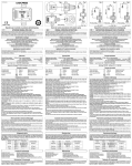
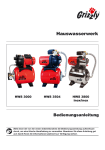
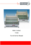
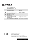
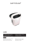
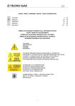
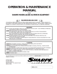
INSTALLATION, USE AND MAINTENANCE INSTRUCTIONS FOR THE AC-CE SERIES BLADDER-TYPE PRESSURE TANKS The ELBI interchangeable bladder-type pressure tanks are available from 5 to 5000 liter capacity that covers every possible water lifting need in hydraulic systems, from the smallest domestic use to the largest industrial applications. ANLEITUNG FÜR MONTAGE, GEBRAUCH UND WARTUNG EINBAU - BEDIENUNGS- UND WARTUNGSVORSCHRIFTEN DER MEMBRANDRUCKKESSEL SERIE AC-CE Esempio di installazione Installation example Exemple d’installation Installationsbeispiel LEGENDA 1. Bulloni controflangia 2. Controflangia 3. Protezione controflangia 4. Membrana 5. Valvola precarica 6. Tappo protezione valvola NOTICES This product is suitable to contain water up to +99°C. Do not exceed the max. working pressure and temperature of the tank; provide suitable controls to avoid that. Provide for an adequate drain system in order to avoid damages in case leaks or tank rupture. During the installation, provide for appropriate discharging and vent valves. During the design we have not considered any external stress like traffic, wind, earthquake. These stress elements should be considered by the Installer during the installation. Observe local regulations for installation. Qualified professional staff must check the system periodically. The manufacturer does not accept any responsibility for material/personal damages due to wrong installation of the vessel. If temperature and pressure limits will be exceeded, manufacturer will not accept any responsibility and warranty claims will be refused. Check the fluid compatibility for liquids different from water. The place of installation should be protected: entry allowed to authorized staff only. The device should be protected by suitable heart dump systems, or insulated from the plant by means of a dielectric joint. 1. If a tank in an existing system is being replaced, make sure that electrical input to the pump electrical control panel is disconnected and that either the water supply is cut off or the system is completely drained. 2. If the existing system uses a traditional tank (without bladder), eliminate the air supply devices and the level indicator, etc. 3. Take the tank out of its package, remove the protection plug (Fig. 4, No. 6) from the air valve and then check the preloading pressure, making sure that this pressure is slightly less than the pressureswitch triggering pressure and adding or removing air as required, and then screw the protection plug back on. 4. Position the tank as close as possible to the pressure-switch in order to avoid pressure losses due to friction. Figures 1,2 and 3 ilustrate the most frequent types of installation. 5. Connect the tank to the water mains or to the pump outlet point, making sure to always respect all local installation regulations. 6. We recommend installing a safety valve set to the system maximum working pressure. 7. Restore the power supply to the pump control panel only after completing the installation of the tank. 8. Fill the system again by starting up the pump until the pressure-switch shuts the pump off automatically. 9. Open and close the cock furthest from the tank repeatedly in order to eliminate all the air inside the tubing. 10. Open one or more cocks in order to empty the tank. If a pause is observed between the emptying of the tank and the starting of the pump, the pressure-switch triggering pressure must be slightly increased (consult the instructions provided by the Manufacturer) or the tank pre-loading pressure must be decreased by proceeding as described in Point 3. 11. Repeat Points 8, 9 and 10 until the pause is completely eliminated. 12. Check all the connections and make sure that there are no leakages of water. 13. If the operations in all the Points above have been perfectly executed, the system should now be ready for operation. 14. Regularly check the tank pre-loading pressure during the use of the system and top up whenever required. Proceed as follows for the replacement of the bladder (See Fig. 4): 1. Disconnect the power supply to the pump electrical control panel and either shut off the water supply or completely drain the system of water. 2. Remove the tank from the system and remove all the pre-loading air by using Valve (5). 3. Position the tank horizontally in order to facilitate the operations that follow. 4. Remove the bolts (1) from the counter-flange (2) and then remove the counter-flange. 5. Remove the old bladder from the tank. 6. Insert the new diaphragm in the tank through the flange hole and then connect the neck of the diaphragm to the flange. 7. Re-assemble the counter-flange and screw the bolts back in place. 8. Re-load the tank pre-loading pressure and check for leakages of air on the counter-flange. 9. Re-connect the tank to the system and follow the instructions prescribed from Point 6 onwards for the verification of correct system operation. MAINTENANCE Before starting any maintenance, disconnect all the electric devices and take care of the pressure and temperature of the system. All the heating system components should be periodically checked by professional people (at least once per year). WARNING: This tank is factory precharged. factory precharge pressure can be adjusted by a professional plumber only and the adjusted pressure level must be stamped in the box below. LEGENDE 1. Schraube 2. Flanschdeckel 3. Flanschdeckeldichtung 4. Membrane 5. Prüf und Füllventil 6. Abdeckkappe. DATI DIMENSIONALI/TECHNICAL DATA/CARACTERISTIQUES TECHNIQUES Capacità / Capacity (litri/liters) Attacco acqua / Fitting connection De H (mm) (mm) Precarica / Precharge 130 205 205 270 270 270 360 230 240 315 430 470 470 365 1,5 1,5 1,5 1,5 1,5 1,5 1,5 (bar) Pressione max. esercizio / Max. allowable pressure (bar) AC-2* AC-5* AC-8 AC-18 AC-25 AC-25 GPM AS-25 2 5 8 18 24 24 24 ¾" ¾" ¾" ¾" – 1" ¾" – 1" ¾" – 1" ¾" – 1" *Esente da marcatura CE: Art. 3 (3) *Free from CE mark: Art. 3 (3) 1. Counterflange bolts 2. Counterflange 3. Counterflange protection 4. Bladder 5. Pre-loading valve 6. Protection cup LEGENDE Modello/ Model TECHNISCHE INFORMATION CAPTION 1. Boullons contrebride 2. Contrebride 3. Protection contrebride 4. Vessie 5. Vanne 6. Bouchon de protection Proceed as follows for pressure tank installation: Die austauschbaren Membrandruckkessel der ELBI werden mit einem Fassungsvermögen von 5 bis 5000 Liter angeboten und eignen sich daher zur Losung von Problemen, die mit dem Heben von Wassern in allen Wasserversorgungsanlagen zu tun haben, von kleinen Anlagen für den Hausgebrauch bis zu großen Industrie anlagen. 8 8 8 8 8 8 8 *Ohone CE markierung : Art. 3 (3) * Exempt de marquage CE: Art. 3 (3) ELBI si riserva il diritto di apportare eventuali variazioni sui dati di questo catalogo senza preavviso. I dati riportati nelle tabelle sono indicativi. ELBI reserves the right of making changes to its products and data shown in this catalogue without notice. All dimensions are subject to the tolerance. ELBI se réserve le droit d’apporter des modifications sur les données des produits sans avis. Les données sont indicatives. Dieses Produkt ist geeignet für Wassertemperaturen bis +99°C. Der max. Druck und die max. Temperatur der Druckkessel dürfen nicht überschritten werden; geeignete Kontrollen sind zu diesem Zweck vorauszusehen. Sorgen Sie für ein adäquates Ablaufsystem um im Falle einer Undichtigkeit oder eines Behälterdefektes Wasserschäden zu vermeiden! Angemessene Ablauf- und Entlüftungssysteme sind während der Anlage zu versehen. Keine Außenbeanspruchungen wie Verkehr, Wind oder Erdbeben sind in der Planung betrachtet worden. Diese müssen von dem Installateur während der Einrichtung in Erwägung gezogen. Das Produkt muß gemäß den gültigen Gesetzen und Vorschriften installiert werden, und sollte nur von Fachkräften geprüft und eingebaut werden. Der Hersteller übernimmt keine Garantie- oder Schadenersatzansprüche bei Nichteinhaltung der Installationsvorschriften oder gültigen Normen. Wird die maximale Temperatur oder der maximale Druck überschritten, lehnt der Hersteller jegliche Garantieansprüche ab. Überprüfen Sie die Verträglichkeit mit Wasserverschiedenen Flüssigkeiten. Der Ort der installierten Einrichtung soll geschützt sein. Unbefugten ist der Zutritt verboten. Die Einrichtung soll mit geeigneter Erdung geschützt oder durch elektrische Verbindung von der Anlage isoliert werden. Für den Einbau des Druckkessels sind folgende Vorschriften zu beachten: 1. Falls Sie einen Behälter in einer bereits bestehende Anlage auswechseln, müssen Sie sicher sein, daß keine Stromversorgung zur Schalttafel der Pumpe besteht und die Wasserversorgung gesperrt oder die Anlage leer ist. 2. Falls in die bestehende Anlage ein traditioneller Behälter (ohne Membrane) eingebaut war, sind die Vorrichtung für die Luftzufuhr, der Standanzeiger, usw., zu entfernen. 3. Die Verpackung vom Behälter entfernen, den Schutzverschluß (Abb. 4 - Nr. 6) des Luftventils abnehmen und den Vordruck kontrollieren; sicherstellen, daß der Vordruck etwas niedriger als der Einschaltdruck des Druckwächters ist, je nach Bedarf Luft im Behälter hinzufügen oder wegnehmen, dann den Schutzverschluß wieder aufschrauben. 4. Den Behälter so nah wie möglich am Druckwächter positionieren, damit Lastverluste vermieden werden; die Abbildungen 1, 2 und 3 zeigen die häufigsten Einbauarten. 5. Den Behälter an das Netz oder den Ausgang der Pumpe anschleißen; gegebenenfalls immer die örtlichen Einbauvorschriften beachten. 6. Der Einbau eines Sicherheitsventils, auf den Maximalbetriebsdruck der Anlage geeicht, wird empfohlen. 7. Die Versorgung zur Schalttafel der Pumpe erst wiederherstellen, nachdem der Behälter richtig eingebaut wurde. 8. Die Anlage füllen, dazu die Pumpe aktivieren, bis der Druckwächter die Pumpe selbsttätig abschaltet. 9. Den Hahn, der am weitesten vom Behälter entfernt ist, mehrmals öffnen und schließen, um die Luft, die sich in den Leitungen befindet, zu beseitigen. 10. Einen oder mehrere Hähne öffnen, um den Behälter zu entleeren; falls eine Pause zwischen dem Entleeren des Behälters und dem Start der Pumpe bemerkt wird, so muß der Einschaltdruck des Druckwächters leicht erhöht (die Anweisungen des Herstellers befolgen) oder der Vordruck des Druckkessels verringert werden, wozu wie in Punkt 3 vorzugehen ist. 11. Die Punkte 8, 9 und 10 wiederholen, bis die Pause nicht mehr besteht. 12. Die Verbindungen genau kontrollieren und prüfen, daß keine Wasserleckagen vorhanden sind. 13. Falls die vorhergehenden Punkte sorgfältig ausgeführt wurden, steht die Anlage für di Inbetriebnahme bereit. 14. Während der Benutzung der Anlage sollte der Vordruck des Druckkessels regelmäßig kontrolliert und gegebenenfalls wieder eingestellt werden. Für den Ersatz der Membrane sind folgende Vorschriften zu beachten (siehe Abb. 4) 1. Die Stromversorgung zur Schalttafel der Pumpe unterbrechen und die Wasserversorgung sperren oder die Anlage entleeren. 2. Den Behälter aus der Anlage ausbauen und die Vorladungsluft mittels des Ventils (5) ganz herauskommen lassen. 3. Den Behälter waagrecht stellen, damit folgende Arbeitsgänge leichter durchgeführt werden können. 4. Die Mutterschrauben (1) des Gegenflansches und den Gegenflansch (2) entfernen. 5. Die alte Membrane und die Stützstange der Membrane aus dem Behälter nehmen. 6. Die neue Membrane durch das Flascheloch in den Behälter einführen, dann den Hals der Membrane am Flasche anhaften lassen. 7. Den Gegenflansch wieder montieren und die Mutterschrauben anziehen. 8. Den Vordruck des Behälters wieder herstellen und prüfen, daß keine Luftverluste am Gegenflansch bestehen. 9. Den Behälter wieder mit der Anlage verbinden und für die Überprüfung des korrekten Betriebs der Anlage die Einbauvorschriften ab Punkt 6 befolgen. WARTUNGSHINWEIS Die Verbindung mit allen elektrischen Ausrüstungen bevor irgendwelche Unterhaltsarbeiten unterbrechen und bei dem Druck und der Temperatur der Anlage sehr aufmerksam sein. Einmal pro Jahr sollten alle Komponenten Ihrer Heizungsanlage von einem konzessionierten Unternehmen auf ordnungsgemäße Funktion überprüft werden. ACHTUNG ELBI Technische Änderungen vorbehalten. Maßangaben sind Außenmasse und sind als Richtwert zu verstehen. ELBI S.p.A. - Via Buccia, 9 - 35010 Limena (PD) - Italy Tel. +39 (049) 8840677 - Fax Amm. +39 (049) 7699675 - Fax Com. +39 (049) 8841610 E-mail: [email protected] www.elbi.it ELBI S.p.A. - Via Buccia, 9 - 35010 Limena (PD) - Italy Tel. +39 (049) 8840677 - Fax Amm. +39 (049) 7699675 - Fax Com. +39 (049) 8841610 E-mail: [email protected] www.elbi.it Dieser Tank ist werkseitig eingestellt. Der Druck kann nur von einem autorisierten Fachmann (Installateur) eingestellt oder verändert werden. Der neu eingestellte Vordruck muss auf dem Gefäß vermerkt werden. ELBI S.p.A. - Via Buccia, 9 - 35010 Limena (PD) - Italy Tel. +39 (049) 8840677 - Fax Amm. +39 (049) 7699675 - Fax Com. +39 (049) 8841610 E-mail: [email protected] www.elbi.it INDICATIONS D’INSTALLATION, UTILISATION ET ENTRETIEN DES RESERVOIRS A VESSIE SERIE AC-CE Les réservoirs à vessie interchangeable ELBI sont fabriqués en une gamme allant de 5 à 5000 litres. Ils sont donc adaptés pour résoudre les problèmes d’élévation des eaux dans toute installation hydraulique, depuis les plus petites pour l’utilisation domestique aux grandes installations industrielles. INSTRUCTIONS Ce produit est destiné à contenir de l’eau jusqu’à +99°C. Ne dépasser jamais la pression et la température maximum d’exercice du réservoir; utiliser systèmes de control appropriés. Prévoir en phase d'installation des systèmes adéquate de drainage pour éviter les dommages conséquents à des pertes de liquide des autoclaves. Utiliser dans l'installation systèmes convenables de déchargement et soupirail. Nous n'avons pas considéré aucune tension extérieure comme le trafic, le vent, le tremblement de terre. Ceux devront être considérées par le plombier pendant l'installation. Installer toujours le vase selon les lois en vigueur. Ce produit doit être installé et contrôlé seulement par des personnes qualifiées. Le constructeur n’est pas responsable pour dommages aux personnes ou matériels que le produit peut causer si installé in manière impropre ou en tous cas pas conforme aux spécifications du constructeur. Dépasser les limites de température et pression définis par le constructeur annule soit la garantie du produit, soit la responsabilité du constructeur. Vérifier la compatibilité des fluides différents de l'eau. Le lieu où le produit est installé doit être protégé et l'entrée consentie seulement à personnel autorisé. L'appareil doit être protégé avec des systèmes appropriés de mis à terre ou isolé au moyen d'un joint diélectrique. Pour l’installation du réservoir, respecter les indications suivantes: 1. En cas de remplacement d’un réservoir dans une installation déjà existante, s’assurer d’avoir mis hors tension le tableau électrique de contrôle de la pompe et d’avoir arrêté l’alimentation d’eau ou d’avoir vidé l’installation. 2. Quand l’installation existante prévoyait un réservoir traditionnel (sans vessie), éliminer les dispositifs d’alimentation d’air, l’indicateur de niveau, etc. 3. Sortir le réservoir de l’emballage, ôter le bouchon de protection (fig. 4 n. 6) de la soupape de l’air et contrôler la pression de pré remplissage; s’assurer que la pression de pré remplissage est légèrement inférieure par rapport à la pression d’intervention du pressostat; augmenter ou diminuer l’air dans le réservoir en fonction des nécessités puis revisser le bouchon de protection. 4. Afin d’éviter des pertes de charge, positionner le réservoir le plus près possible du pressostat; les cas les plus fréquents d’installation sont illustrés sur les figures 1,2 et 3. 5. Brancher le réservoir au réseau ou à la sortie de la pompe; respecter toujours les normes locales pour l’installation. 6. Il est recommandé d’installer une soupape de sécurité réglée sur la pression maximum de fonctionnement de l’installation. 7. Ne pas rétablir l’alimentation au tableau électrique de la pompe avant d’avoir terminé correctement l’installation du réservoir. 8. Remplir l’installation en actionnant la pompe jusqu’à ce que le pressostat la désactive automatiquement. 9. Ouvrir et fermer plusieurs fois le robinet le plus éloigné du réservoir afin d’éliminer tout l’air contenu à l’intérieur des conduites. 10. Ouvrir un ou plusieurs robinets pour vider le réservoir; si on remarque une pause entre le vidage du réservoir et le démarrage de la pompe, il faut augmenter légèrement la pression d’intervention du pressostat (consulter les instructions du fabricant) ou diminuer la pression de pré remplissage du réservoir en agissant comme au point n. 3. 11. Répéter les opérations des points 8, 9, 10 jusqu’à la complète élimination de la pause. 12. Contrôler soigneusement les joints et vérifier qu’il n’y ait pas de fuites d’eau. 13. Si les points précédents ont été scrupuleusement suivis, l’installation est prête pour entrer en fonction. 14. Pendant l’utilisation de l’installation, il est conseillé de contrôler périodiquement et avec attention la pression de pré remplissage du réservoir et, éventuellement, de la rétablir. NORME DI INSTALLAZIONE, USO E MANUTENZIONE DELLE AUTOCLAVI A MEMBRANA SERIE AC-CE DICHIARAZONE DI CONFORMITA’ CONFORMITY DECLARATION DECLARATION DE CONFORMITE KONFORMITÄTSERKLÄRUNG ELBI S.p.A. dichiara sotto la propria responsabilità che questo serbatoio a pressione è stato progettato, fabbricato e collaudato in conformità a quanto prescritto dalla Direttiva Europea 97/23/CE PED del 29 Maggio 1997 Rientra nella categoria I ed è stato applicato il modulo A Le autoclavi a membrana intercambiabile ELBI sono sviluppate in una gamma che va da 5 a 5000 litri, e si adattano quindi a risolvere i problemi di sollevamento acque in tutti i tipi di impianto idrico, da quello piccolo di uso domestico ai grossi impianti industriali. AVVERTENZE ELBI S.p.A. declares, under its own responsibility, that this Pressure Vessel was designed, manufactured, and inspected in conformity with the European Directive 97/23/EC – PED on the 29 May 1997 Belonging to the category I and using the procedure A La société ELBI S.p.A déclare sous sa propre responsabilité que ce réservoir à pression a été projeté, fabriqué, et essayé conformément à la Directive Européenne 97/23/CE – PED du 29 Mai 1997 Et qui sont des catégories I avec la procédure A Die Firma ELBI S.p.A. erklärt in eigener Verantwortung, dass sie gemäß den Europäischen Vorschriften Nr. 97/23/CE – PED welche am 29 Mai 1997 Welche der Kategorie I sowie nach Prozedur A Numero di Fabbrica – Serial Number Numéro de Série – Serien Nummer Data di Fabbricazione – Manufactured Date Date de Construction - Herstellungsjahr VEDI ETICHETTA SUL VASO SEE LABEL ON THE TANK VOIR ETIQUETTE SUR LE RESERVOIRS SEHEN SELBSTKLEBENDES Questo prodotto è destinato al contenimento di acqua fino a +99°C. Non superare mai la pressione e la temperatura massime di esercizio del serbatoio; prevedere idonei controlli a tale scopo. Prevedere in fase di installazione adeguati sistemi di drenaggio per evitare i danni conseguenti a perdite di liquido da parte dell’autoclave. Prevedere in fase di installazione adeguati sistemi di scarico e sfiato. Non sono state considerate in fase di progetto sollecitazioni esterne quali: traffico, vento, terremoti. Queste dovranno essere tenute in considerazione dall'installatore in fase di installazione. Installare sempre l'apparecchiatura in conformità alle leggi vigenti. Questo prodotto deve essere installato e controllato periodicamente esclusivamente da personale qualificato. Il costruttore non accetta alcuna responsabilità per danni personali e materiali che il prodotto possa causare se installato e/o utilizzato in maniera impropria o comunque in difformità da quanto specificato dal costruttore. Il superamento dei limiti di temperatura e pressione definiti dal costruttore annulla ogni garanzia sul prodotto nonché ogni responsabilità dei costruttore. Verificare la compatibilità con fluidi diversi dall'acqua. Il luogo in cui viene installata l'apparecchiatura deve essere protetto, e l'accesso deve essere consentito solo a personale autorizzato. L'apparecchiatura deve essere protetta con idonei sistemi di messa a terra, o isolata dall'impianto mediante giunto dielettrico. Per l’installazione dell’autoclave attenersi alle seguenti prescrizioni: 1. Se state sostituendo un serbatoio in un impianto esistente, assicuratevi di togliere l’alimentazione al quadro elettrico di controllo della pompa e di intercettare l’alimentazione dell’acqua o scaricare l’impianto. 2. Se l’impianto esistente utilizzava un serbatoio tradizionale (senza membrana), eliminare i dispositivi di alimentazione dell’aria, l’indicatore di livello, ecc. 3. Togliere l’imballo del serbatoio, rimuovere il tappo di protezione (fig. 4 n. 6) della valvola dell’aria e controllare la pressione di precarica; assicurarsi che la pressione di precarica sia leggermente inferiore alla pressione di inserimento del pressostato; aggiungere o togliere aria al serbatoio secondo la necessità, e riavvitare il tappo di protezione. 4. Posizionare il serbatoio il più vicino possibile al pressostato, per evitare le perdite di carico; le figure 1, 2 e 3 illustrano i frequenti tipi di installazione. 5. Collegare il serbatoio alla rete o all’uscita della pompa; osservare sempre le eventuali norme locali di installazione. 6. Si raccomanda l’installazione di una valvola di sicurezza tarata alla massima pressione di esercizio dell’impianto. 7. Ripristinare l’alimentazione al quadro della pompa solo dopo aver completato correttamente l’installazione del serbatoio. 8. Riempire l’impianto attivando la pompa fino a che il pressostato la disinserisce automaticamente. 9. Aprire e chiudere ripetutamente il rubinetto più lontano dal serbatoio per eliminare tutta l’aria che si trova all’interno delle tubazioni. 10. Aprire uno o più rubinetti per svuotare il serbatoio; se si riscontra una pausa tra lo svuotamento del serbatoio e la partenza della pompa è necessario aumentare leggermente la pressione di inserimento del pressostato (consultare le istruzioni del fabbricante) o diminuire la pressione di precarica dell’autoclave, agendo come al passo n. 3. 11. Ripetere i passi 8, 9 e 10 fino alla completa eliminazione della pausa. 12. Controllare bene le giunzioni e verificare che non vi siano eventuali perdite d’acqua. 13. Se i punti precedenti sono stati seguiti scrupolosamente, l’impianto è pronto per entrare in servizio. 14. Durante l’uso dell’impianto, è bene controllare periodicamente la pressione di precarica dell’autoclave ed eventualmente ripristinarla. Pour le remplacement de la vessie, respecter les indications suivantes (réf. fig. 4): Per la sostituzione della membrana attenersi alle seguenti prescrizioni (rif. fig. 4): 1. Mettre hors tension le tableau électrique de contrôle de la pompe et arrêter l’alimentation de l’eau ou vider l’installation. 2. Démonter le réservoir de l’installation et enlever tout l’air de pré remplissage en agissant sur la soupape (5). 3. Positionner horizontalement le réservoir afin de faciliter les opérations suivantes. 4. Enlever les boulons (1) de la contre-bride et enlever la contre-bride (2). 5. Enlever la vessie du réservoir. 6. Introduire la nouvelle vessie dans le réservoir par le trou de la bride. Faire adhérer le collier de la vessie à la bride. 7. Assembler de nouveau la contre-bride et visser les boulons. 8. Rétablir le pré remplissage du réservoir et vérifier qu’il n’y ait pas de fuites d’air sur la contre-bride. 9. Raccorder de nouveau le réservoir à l’installation, suivre les indications d’installation à partir du point n. 6 pour le contrôle du fonctionnement correct de l’installation. 1. Togliere l’alimentazione al quadro elettrico di controllo della pompa e intercettare l’alimentazione dell’acqua o scaricare l’impianto. 2. Smontare il serbatoio dall’impianto e rimuovere tutta l’aria di precarica, agendo sulla valvola (5). 3. Posizionare il serbatoio orizzontalmente per facilitare le operazioni che seguono. 4. Rimuovere i bulloni (1) della controflangia e togliere la controflangia (2). 5. Rimuovere la vecchia membrana dal serbatoio. 6. Inserire la nuova membrana nel serbatoio dal foro della flangia facendo aderire il collo della membrana alla flangia. 7. Riassemblare la controflangia ed avvitare i bulloni. 8. Ripristinare la precarica dal serbatoio e verificare eventuali perdite d’aria sulla controflangia. 9. Ricollegare il serbatoio all’impianto, seguire le norme di installazione dal passo n. 6 per la verifica del corretto funzionamento dell’impianto. __________________________ ENTRETIEN IMPORTANTE: ATTENTION: La valeur de precharge du réservoir, dans le cas où résulte varié à ce qui a été établi avant, doit être mentionné d'une manière indélébile sur l'étiquette par un technicien certifié ELBI S.p.A. - Via Buccia, 9 - 35010 Limena (PD) - Italy Tel. +39 (049) 8840677 - Fax Amm. +39 (049) 7699675 - Fax Com. +39 (049) 8841610 E-mail: [email protected] www.elbi.it MANUTENZIONE Prima di iniziare qualsiasi attività di manutenzione scollegare tutte le apparecchiature elettriche e fare attenzione alla pressione e temperatura dell'impianto. Si raccomanda che l'intero impianto sia revisionato da un installatore professionista almeno una volta l'anno. Durante tale controllo è opportuno venga verificata, ed eventualmente corretta, la pressione di precarica del vaso per mantenere le prestazioni a livello ottimale. Avant l'entretien, disjoindre tous les appareils électriques et faire attention à la température et la pression du système. Il est recommandé que le système de chauffage soit contrôlé par un installateur professionnel au moins une fois par année: pendant ce contrôle il est convenaient de vérifier et, si nécessaire, corriger la pression de pré charge air. 7050022 – 12/2012 ELBI S.p.A. - Via Buccia, 9 - 35010 Limena (PD) - Italy Tel. +39 (049) 8840677 - Fax Amm. +39 (049) 7699675 - Fax Com. +39 (049) 8841610 E-mail: [email protected] www.elbi.it Il valore di precarica del serbatoio, se variato rispetto a quello preimpostato, deve essere riportato in modo indelebile nell' apposito spazio della targhetta da un tecnico abilitato. ELBI S.p.A. - Via Buccia, 9 - 35010 Limena (PD) - Italy Tel. +39 (049) 8840677 - Fax Amm. +39 (049) 7699675 - Fax Com. +39 (049) 8841610 E-mail: [email protected] www.elbi.it