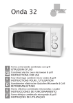
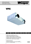
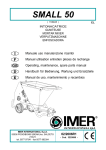
1
DIMENSIONI CAVE Dl INSTALLAZIONE
DIMENSIONS ENCOCHES D’INSTALLATION / CUT-OUT DIMENSIONS
DIMENSIONES RANURAS DE INSTALACIÓN / ABMESSUNGEN DER EINBAUNISCHEN
SERIE
SERIES
FORO
CUT-OUT
IN MM
CAVA
CUT-OUT
IN MM
CLASSE
ISOLAMENTO
INSULATION
CLASS
DISTANZA
OGGETTO
DISTANCE
OBJECT
CLEF 17
CLEF 150 R
156
-
I
1m
CLEF 22
CLEF 200 R
205
-
I
1m
CLEF 26
CLEF 250 R
253
-
I
1m
TABELLA 1
2 CLEF 17-22-26 - CLEF 150R-200R-250R
LAMPADE A SCARICA
CLEF 17-22-26 - CLEF 150R-200R-250R DISCHARGE LAMPS
CLEF 17-22-26 - CLEF 150R-200R-250R LAMPES A DECHARGE
CLEF 17-22-26 - CLEF 150R-200R-250RNTLADUNGSLAMPEN
CLEF 17-22-26 - CLEF 150R-200R-250RLÁMPARAS DE DESCARGA
I
Collegare il cavo di uscita dell’apparecchio ad un sistema di alimentazione
(reattore + accenditore) idoneo al tipo e potenza della lampada.
In funzione della potenza di lampade da installare, applicare all’interno del
vano ottico la relativa targhetta in allegato. Tutti gli apparecchi a ioduri metallici
devono utilizzare solo lampade con filtro UV.
Per apparecchi con attacco G 12 e PG 12 il cavo bianco in doppio isolamento
deve essere collegato all’uscita dell’accenditore contrassegnata dal simbolo
uscita alta tensione).
Il conduttore giallo-verde deve essere collegato alla terra contrassegnata dal
simbolo (FIG. 2).
Nel caso di utilizzazione dei nostri sistemi di alimentazione tipo CJ70 (70W),
CJ15 (150W), CJ25 (250W) collegare il cavo di rete e i cavi dell’apparecchio ai
relativi morsetti a 3 poli ad innesto rapido (FIG. 2).
Eseguire le connessioni rispettando i colori dei cavi e le avvertenze sul morsetto La.
I
Alloggiare l’apparecchio nel foro del controsoffitto agendo sulle molle
(FIG. 5-6-7-8-9).
Per la pulizia della parabola utilizzare un panno morbido (non utilizzare
solventi tipo alcool o prodotti abrasivi).
I
Dove l’apparecchio è sprovvisto di alimentatori propri collegarelo stesso
ad un sistema di alimentazione idoneo al tipo e potenza di lampada .
Nel caso di utilizzazione dei nostri sistemi di alimentazione
elettromeccanico ed elettronico collegare il cavo in uscita
dell’apparecchio con blocchetto alla presa idonea, mentre il cavo di rete
al relativo morsetto ad innesto rapido.
Eseguire le connessioni rispettando i colori dei cavi (FIG. 3-4).
GB
Place the light fitting in the hole of the false ceiling acting on the springs
(FIG. 5-6-7-8-9).
For the cleaning of the reflector use a soft cloth (do not use solvents
alcohol or abrasive products).
GB
Where the light fitting does not have its own control gear, connect the same
to a control gear box suitable to the type and power of the lamp.
In case af use of our control gear boxes conventional and electronic ballast
connect the outlet cable of the light fitting with terminal block to the suitable
socket, and the 230V network cable to the relative rapid coupling terminal.
Execute the connections respecting the colors of the cables (FIG.3-4).
F
Loger l’appareil dans le trou du faux plafond agissant sur les ressorts
(FIG. 5-6-7-8-9).
Pour le nettoyage de lo parabole utiliser un linge moelleux (ne pas utiliser
solvants, alcool ou produits abrasifs).
D
Die Leuchte in die in der abgehängten Decke vorgesehene Bohrung
einsetzen. Dazu auf die Federn (FIG. 5-6-7-8-9) drücken. Die Reflektor mit
einem weichen Tuch reinigen (keine Lösungsmittel, Alkohol oder scheuernde
Produkte verwenden).
F
Là où l’appareil est dépourvu d’alimentation propres, connecter le même à
un système d’alimentation approprié au type et puissance de la lampe.
Dans le cas d’utilisation de nos systèmes d’alimentation avec alimentation
électromecanique et électronique connecter l câble en sortie de l’appareil à
la prise appropriée, le câble de réseau 230 V à la relative borne à
embrayage rapide. Exécuter les connexions en respectant les couleurs des
câbles (FIG. 3-4).
E
Insertar el aparato en el taladro del contratecho obrando sobre los muelles
(FIG. 5-6-7-8-9).
Para limpiar la parábola utilizar un trapo suave (no utilizar solventes como
productos limpiacristales, alcohol o productos abrasivos).
D
Falls das Gerät kein eingebautes Vorschaltgerät hat, ist es an ein
Versorgungssystem anzuschließen, das dem Typ und der Leistung der Lampe
entspricht.
Beim Einsatz unserer Vorschgltaeräte vom mit vorschaltgerat konventionell
und elektronisch das vom Gerät abgehende Kabel mit anschlulßklemme an
eine geeignete Steckdose anschließen, während das Netzkabel von 230 V
an die entsprechende Schnellsteckklemme angeschlossen wird.
Beim Ausführen der Anschlüsse die Farben der Kabel einhalten (FIG.3-4).
E
En caso de que el aparato carezca de alimentadores proprios, conectarlo a
un sistema de alimentación apto para el tipo y la potencia de la lámpara.
En caso de utilizarse nuestros sistemas de suministro con reactancia
electronica e normal, conectar el cable de salida del aparato con caja de
derivación al enchufe correspondiente, y el cable de red 230 V al
correspondiente borne de acoplamiento rápido.
Realizar las conexiones respetando los colores de los cables (FIG .3-4) .
Alimentazione
Mains
Corpo illuminante
Light fitting
Fori fissaggio
Fixing hooks
fig.1
FIG. 6
mi
n3
0c
m
MONOLAMPADA MONOLAMPADA
ONE LAMP
ONE LAMP
FIG.1
MONTAGEANWEISUNGEN CLEF 17-22-26 - CLEF 150R-200R-250R
Corpo illuminante
Light fitting
APPAREILS EN EMERGENCE POUR LAMPES FLUORESCENTES COMPACTES
NOTLICHTLEUCHTE FÜR KOMPAKTLEUCHSTOFFLAMPEN
APARATOS DE EMERGENCIA PARA LÁMPARAS FLUORESCENTES COMPACTAS
I
ISTRUZIONI Dl INSTALLAZIONE USO E MANUTENZIONE
Attenzione!!! Prima di effettuare i collegamenti elettrici, durante il montaggio
o sostituzione delle lampade, assicurarsi di aver tolto tensione e prendere
visione degli schemi FIG. 9.
Nell’installazione operare come segue:
- collegare alla rete il gruppo INVERTER tramite il morsetto di rete (1).
- collegare alla rete il gruppo ALIMENTATORI tramite il morsetto di rete (2).
- collegare tra loro i 2 gruppi tramite la spina (B) e la presa (B1).
- inserire il LED (L) sulla parabola dell’apparecchio di emergenza.
- alimentare i due gruppi INVERTER e ALIMENTATORI,
collegare i cavi + e - alla batteria
N.B.: secondo le norme vigenti occorre sostituire le batterie
quando non garantiscono più la loro autonomia minima.
CASSETTE Dl ALIMENTAZIONE
CEF 3030 (2x13W) - CEF 3040 (2x18W) - CEF 3050 (2x26W)
CARATTERISTICHE TECNICHE
Funzionamento: - Di tipo SA (permanente) per apparecchi da
incasso bilampada
- Una sola lampada viene alimentata in emergenza
Alimentazione: - 230V 50Hz con due ingressi
indipendenti per il gruppo INVERTER
e il gruppo ALIMENTATORI.
Autonomia:
- 1 ora minimo
Fattori di flusso - 30% per lampade compatte 10/13W
- 25% per lampade compatte 18W
- 20% per lampade compatte 26W
Batterie:
- Ni Cd 3,6V- 4Ah
Tempo di carica: - 24 ore
INSTRUCTIONS OF INSTALLATION, USE AND MAINTENANCE
Warning!!! Before effecting the electric connections, during the assembly,
replacement of the lamps, be sure that the voltage has been removed and
take vision of schemes FIG. 9.
In the installation operate as follows
- connect the INVERTER group to the network by means of the network
terminal (1).
- connect the GEAR BOX to the network by means of the network terminal (2).
- connect the 2 groups between themselves by means of the plug (B) and the
socket (B1).
- insert the LED (L) on the reflector of the emergency light fixture.
- connect the inverter and gear box to the mains, connect the + and - cables
to the battery.
P.S. as by the norms in force the batteries must be replaced
when they do not guarantee their minimum autonomy.
CONTROL GEAR BOXES
CEF 3030 (2x13W) - CEF 3040 (2x18W) - CEF 3050 (2x26W)
FIG. 5
TECHNICAL CHARACTERISTICS
Functioning:
- Of the SA type (permanent) for recessed down lights
with two lamps
- Only one lamp functions in emergency
Feeding:
- 230 V 50 Hz with two independent inlets for the
INVERTER group and the BALLAST group
Autonomy:
- minimum 1 hour
Flow factors:
- 30% for compact lamps 10/13W
- 25% for compact lamps 18W
- 20% for compact lamps 26W
Batteries:
- Ni Cd 3,& V - 4Ah
Charge time:
- 24 hours
DD
B
Alimentazione
Mains
N
L
B
Alimentazione
Mains
N La
min 30 cm
FIG. 3
= GIALLO - VERDE
Yellow - Green
La
N
A
C
La
FIG.2
BILAMPADA
TWO LAMPS
F
FIG. 7
Corpo illuminante
Light fitting
Alimentazione
Mains
FIG. 4
FIG. 8
FIG. 9
2
230 V
BOITES D’ALIMENTATION
CEF 3030 (2x13W) - CEF 3040 (2x18W) - CEF 3050 (2x26W)
CARACTERISTIQUES TECHNIQUES
Fonctionnement: - Du type SA (permanent) pour appareils encastrés bilampe
- Une seule lampe est alimentée en émergence
ALIMENTATION: - 230 V 50 Hz avec deux accès indépendents pour
le qroupe INVERSEUR
et le groupe ALIMENTATEURS
Autonomie:
- 1 heure minimum
Facteurs de débit: - 30% pour lampe compacte 10/13W
- 25% pour lampe compacte 18W
- 20% pour lampe compacte 26W
Batterie:
- Ni Cd 3,6V - 4Ah
Temps de charge: - 24 heures
D
EINBAU-, BEDIENUNGS- UND WARTUNGSANWEISUNGEN
Achtung!!! Bevor bei der Montage oder dem Austausch der Lampen die
elektrischen Anschlüsse ausgeführt werden, vergewissern Sie sich, daß keine
Spannung mehr anliegt, und begutachten Sie die Schaltpläne in den FIG. 9.
Beim Einbau wie folgt vorgehen:
- die Invertergruppe mit Hilfe der Netzklemme (1) an das Netz anschließen;
- die Netzteilgruppe mit Hilfe der Netzklemme (2) an das Netz anschließen;
- die 2 Gruppen untereinander mit Hilfe des Steckers (B) und der Steckdose
(B1) verbinden;
- das LED (L) in den Reflektor der Notlichtleuchte einsetzen;
- zur Stromversorgung für Inverter und Vorschaltgerät die Kabel + und - an die
Batterie anschlielßen.
Anmerkung: Gemäß den geltenden Richtlinien sind die
Batterien auszuwechseln, sobald deren Mindestautonomie
nicht mehr gewährleistet ist.
GRUPPO ALIMENTATORI
A1
230 V
A
+
-
-
+
VORSCHALTGERÄTE
CEF 3030 (2x13W) - CEF 3040 (2x18W) - CEF 3050 (2x26W)
TECHNISCHE MERKMALE
Betrieb:
- vom Typ SA (Dauerbetrieb) für Einbauleuchte mit
zwei Lampen
- im Notfall wird nur eine Lampe mit Strom versorgt
Stromversorgung: - 230 V 50 Hz mi zwei unabhängigen Eingängen
für die Invertergruppe und das Vorschalgerät.
Autonomie:
- mindestens 1 Sunde
Flussfaktoren:
- 30% bei Kompaktlampen 10/1 3W
- 25% bei Kompaktlampen 18 W
- 20% bei Kompaktlampen 26 W
Batterien:
- Ni Cd 3,6 V - 4Ah
Ladedauer:
- 24 Stunden
B1
B
GRUPPO INVERTER
E
INSTRUCCIONES DE INSTALACIÓN, USO Y MANTENIMIENTO
Atención!!! Durane el montaje y el cambio de las lámparas, antes de efectuar
las conexiones eléctricas, comprobar que se haya desconectado la tension y
consultar los esquemas FIG. 9.
Para efectuar la instalación, proceder de la siguiente manera:
- conectar el grupo INVERSOR a la red mediante el borne de red (1)
- conectar el grupo ALIMENTADORES a la red mediante el borne de red (2)
- conectar los 2 grupos el uno al otro mediante la clavija (B) y el enchufe (B1)
- inserir el LED (L) en el reflector de la luminária para luz de emergencia;
- poner bajo tensión los dos grupos INVERSOR y ALIMENTADORES,
conectar los cables + y - a la bateria.
N.B.: de acuerdo con las normas vigentes, es preciso
cambiar las baterias cuando dejan de garantizar su
autonomia minima.
L
230 V
CAJAS DE SUMINISTRO
CEF 3030 (2x13W) - CEF 3040 (2x18W) - CEF 3050 (2x26W)
CARACTERISTICAS TECNICAS
Funcionamiento: - de tipo SA (permanente) para aparatos a empotrar
de dos lámparas
- en caso de emergencia, una sola lámpara se pone
bajo tensión
Suministros:
- 230 V 50 Hz con dos entradas independientes para el
grupo INVERSOR y el grupo ALIMENTADORES.
Autonomía:
- 1 hora mínimo
Factores de flujo: - 30% para lámparas compactas 10/13 W
- 25% para lámparas compactas 18 W
- 20% para lámparas compactas 26 W
Baterias:
- Ni Cd 3,6 V- 4Ah
Tiempo de carga: - 24 horas
ALIMENTAZIONE INVERTER
MAINS INVERTER
1
230 V
L
Corpo illuminante
Light fitting
INSTRUCTIONS D’INSTALLATION UTILISATION ET ENTRETIEN
Attention!!! Avant d’effectuer les connexions électriques, durant le montage
ou remplacement des lampes, s’assurer d’avoir enlevé la tension et prendre
vision des schémas FIG. 9.
Pour l’installation opérer de la façon suivante:
- connecter au réseau le groupe INVERSEUR par l’entremise de la borne de
réseau (1)
- connecter au réseau l’ALIMENTATION par l’entremise de la borne de
réseau (2).
- connecter entre eux les 2 groupes par l’entremise de la fiche (B) et la prise (B1),
- insérer le LED (L) sur le réflecteur de l’appareil d’émergence.
- alimenter les deux groupes INVERSEUR et ALIMENTATION, connecter les
câbles + et - à la batterie.
P.S.: selon les normes en vigueur il faut remplacer les
batteries quond elles ne garantissent plus leur autonomie
minimum.
ALIMENTAZIONE
MAINS
N
I
DISPOSITIVO DI ANCORAGGIO DEI CAVI
Fissare la parte inferiore del dispositivo di ancoraggio A sotto il supporto
morsettiera mediante le viti di fissaggio C.
Dopo aver cablato l’apparecchio inserire il coperchio del dispositivo di
ancoraggio B nell’apposita sede fissandolo mediante le viti D (FIG. 2).
GB
CABLE CLAMP(S)
Fix the lower part of the cable clamp (“A”) beneath the terminal block
support with fixing screws “C”.
Once the fixture has been wired, insert cable clamp cover in position
and secure with fixing screws “D” (picture no. 2).
7
BILAMPADA
TWO LAMPS
INSTRUCCIONES PARA EL MONTAJE CLEF 17-22-26 - CLEF 150R-200R-250R
IN EMERGENZA PER LAMPADE FLUORESCENTI COMPATTE
5 APPARECCHI
EMERGENCY LIGHT FITTING FOR COMPACT FLUORESCENT LAMPS
GB
L
F
Connecter le câble de sortie de l’appareil à un système d’alimentation (ballast +
allumeur) approprié au type et puissance de la lampe.
En fonction de la puissance de la lampe, il faut appliquer à l’intérieur du
réflecteur l’étiquette appropriée, fournie avec l’encastré. Utiliser pour les
appareils pour iodures métalliques seulement lampes avec filtre UV.
Pour appareils avec douille G12 ou PG 12, le câble blanc en double isolation
doit être connecté à la sortie de l’allumeur marqué par le symbole (sortie
haute tension).Le conducteur jaune-vert doit être connecté à la terre marquée par
le symbole
(FIG. 2).
IP 54
INSTALLATIONS ET ENTRETIEN
EINBAU UND WARTUNG
INSTALACIÓN Y MANTENIMIENTO
N
GB
Connect the secundary cable of the light fitting to a control gear box (ballast +
ignitor) suitable to the type and power of the lamp.
Attach at the inside of the reflector the lable corresponding to the rating of the
lamp to be used. For light fittings for metal halide lamps, you should use only
lamps with UV filter.
For lamps with G12 and PG12 socket, the white cable in double insulation must be
connected to the outlet of the ignitor marked by the symbol (high voltage outlet).
The yellow -green conductor must be connected to the earth marked by the
symbol (FIG.2).
In case of use of our control gear boxes type CJ70 (70W), CJ15 (150W), CJ25
(250W) connect the network cable and the cables of the light fitting to the
relative 3 poles with rapid coupling terminals (FIG. 2).
During connection, respect the colors of the cobles and the warning on the La
terminal.
E
Conectar el cable de salida del aparato a un sistema de suministro (reactor
+ encendedor) apto para el tipo y la potencia de la lámpara.
En funcion de la potencia de la lámpara, aplicar en el interior de la
parabola, la relativa etiqueta. Para todos los aparatos para halogenuro
metalico, utilizar solamente lámparas con filtro UV. Para aparatos con
soquete G12 o PG12, el cable blanco de aislamiento doble se debe
conectar a la salida del encendedor contramarcada con el simbolo salida
alta tensión).
El condudor amarillo-verde se debe conecor a la salida de tierra
cantramarcada con el símbolo (FIG. 2).
En caso de utilizarse nuestros sistemas de suministros tipo CJ70 (70W),
CJ15 (150W), CJ25 (250W) conectar el cable de red 230 V y los cables
del aparato a los correspondientes bornes de 3 polos de acoplamiento
rápido (FIG.1-2). Hacer las conexiones respectando a los colores de los
cables y las advertencias en el borne La.
E MANUTENZIONE
4 INSTALLAZIONE
INSTALLATION AND MAINTENANCE
CLEF 17-22-26 - CLEF 150R-200R-250R FLUORESCENT
CLEF 17-22-26 - CLEF 150R-200R-250R FLUORESCENTES
CLEF 17-22-26 - CLEF 150R-200R-250R LEUCHTSTOFF
CLEF 17-22-26 - CLEF 150R-200R-250R FLUORESCENTES
L
Predisporre nel controsoffitto un foro o cava con le dimensioni riportate nella
TABELLA 1.
Prepare in the false ceiling a hole or slot with the dimensions indicated in
TABLE 1.
Préparer dans le faux plafond un trou ou encoche avec les dimensions
indiquées dans le TABLEAU 1.
In der abgehängten Decke eine Bohrung oder eine Nische gemäß den in
TABELLE 1 angegebenen Abmessungen vorbereiten.
Preparar en el contratecho un taladro o una ranura con las dimensiones
indicadas en la TABLA 1.
D
Das Kabel am Geräteausgang mit einem Gerätekast verbinden
(Vorschaltgerät + Zundgerät), das dem Typ und der Leistung der Lampe
entspricht.
Abhängig von der Lampenstärke sollten Sie das übereinstimmende Etiket auf
der Innenseite des Reflektors anbringen. Für alle metalldampfleuchten, sollten
Sie nur Lampen mit UV Filter anwmeden. Für Leuchten mit G12 und PG12
Fassung muss das doppelt isolierte weiße Kabel am Ausgang des
Zundgerätsangeschlossen werden, der mit dem Symbol
(Spannungsausgang) gekennzeichnet ist.
Der gelb-grüne Leiter muß an die Erde angeschlossen werden, die
mit dem Symbol gekennzeichnet ist (FIG. 2).
Beim Einsatz unserer Versorgungssysteme vom Typ CJ70 (70W), CJ15
(150W), CJ25 (250W) das Netzkabel von 230 V und die Kabel des Geräts
an die entsprechenden, dreipoligen Schnellsteckklemmen anschließen
(FIG. 2).
Während der elektrische Anschluß, sollten Sie die Farben der Kabel und die
Anweisungen der La.
3 CLEF 17-22-26 - CLEF 150R-200R-250R
FLUORESCENTI
N
DIMENSIONS TROUS D’INSTALLATION
ABMESSUNGEN DER EINBAUNISCHEN
DIMENSIONES DE LAS RANURAS DE INSTALACIÓN
Dans le cas d’utilisation de nos systèmes d’alimentation type CJ70 (70W),
CJ15 (l50W), CJ25 (250W) connecter le câble réseau et les câbles de
l’appareil aux relatives bornes à 3 pôles à embrayage rapide (FIG 2).
Faire les connexions en respectant les couleurs des câbles et les instructions
sur la borne La.
INSRTUCTIONS DE MONTAGE CLEF 17-22-26 - CLEF 150R-200R-250R
L
CAVE Dl INSTALLAZIONE
1 DIMENSIONI
CUT-OUT DIMENSIONS
ASSEMBLY INSTRUCTIONS CLEF 17-22-26 - CLEF 150R-200R-250R
N
ISTRUZIONI DI MONTAGGIO CLEF 17-22-26 - CLEF 150R-200R-250R
FIG. 9
ISTRUZIONI DI MONTAGGIO CLEF 17-22-26 - CLEF 150R-200R-250R ASSEMBLY INSTRUCTIONS CLEF 17-22-26 - CLEF 150R-200R-250R INSTRUCTIONS DE MONTAGE CLEF 17-22-26 - CLEF 150R-200R-250R MONTAGEANWEISUNGEN CLEF 17-22-26 - CLEF 150R-200R-250R INSTRUCCIONES PARA EL MONTAJE CLEF 17-22-26 - CLEF 150R-200R-250R
CON PARABOLA ASPORTABILE
6 INCASSI
RECESSED LIGHT FITTING WITH REMOVABLE REFLECTOR
ENCASTRÉS AVEC PARABOLE ENLEVABLE
EINBAULEUCHTEN MIT ABNEHMBARER REFLEKTOR
EMPOTRABLES CON PARABOLA DESMONTABLE
I
- Assicurarsi che l’impianto elettrico non sia sotto tensione.
- Togliere la parabola dalla propria sede, evitando di toccarla con le mani
(FIG. 12B) - (si consiglia l’utilizzo di un panno soffice, in alternativa
guanti in plastica) - ed eseguire correttamente le connessioni elettriche,
facendo attenzione di collegare il cavo di terra giallo e verde nella sede
con il relativo simbolo (FIG. 11).
- Per incassi con schermo policarbonato dopo aver tolto lo schermo stesso,
svitare la vite centrale di tenuta della parabola (FIG. 12B-C).
- Inserire l’apparecchio nel foro da incasso premendo la staffa di ritenuta
(FIG. 14).
- Fissare l’apparecchio spingendo l’anello esterno sul piano del
controsoffitto quindi recuperare la staffa di ritenuta contro il piano interno
e bloccare le viti con la chiave esagonale da mm. 3 (FIG. 15).
- Rimontare la parabola nella propria sede (FIG. 13).
- Per la pulizia della parabola utilizzare un panno morbido (non utilizzare
solventi tipo alcool o prodotti abrasivi).
GB
I
- Prima di eseguire le connessioni di rete, durante il montaggio o
sostituzione delle lampade, assicurarsi di aver tolto tensione.
- Nell’uso di apparecchi per lampade alogene e ad alogenuri, assicurarsi
che la distanza tra le lampade e l’oggetto illuminato non sia inferiore a 1
m. come indicato dal relativo simbolo
- Non utilizzare gli apparecchi senza il vetro o schermo di protezione e
sostituirlo nel caso se ne osservino incrinature o fessurizzazioni.
- Per una corretta installazione eseguire le seguenti operazioni:
1 - Disimballare l’apparecchio e controllare che non presenti difetti dovuti
al trasporto.
2 - Contrassegnare il soffitto con l’apposita dima inserita nell’imballo ed
eseguire i 3 fori con una punta da trapano idonea.
3 - Inserire nei 3 fori i relativi tasselli con le 3 viti (FIG. 16).
4 - Inserire il cavo di alimentazione attraverso il passacavo posto sulla
parte superiore dell’apparecchio, agganciare e bloccare il contenitore
con le 3 viti.
5 - Collegare il cavo di rete alla morsettiera. Il conduttore giallo-verde deve
essere collegato alla terra contrassegnata dal simbolo (FIG. 17)
Per apparecchi con lampade a fluorescenza collegare il blocchetto
nell’apposita sede, mentre per quelli a scarica collegare l’apparecchio
al contenitore utilizzando la morsettiera maschio/femmina in allegato.
6 - Inserire l’apparecchio nel contenitore, agendo sulle molle. Per gli
apparecchi con schermo in policarbonato, svitare la vite centrale di
tenuta della parabola, dopo aver tolto lo schermo, quindi recuperare la
staffa di ritenuta contro il bordo interno del contenitore e bloccare le viti
con la chiave esagonale di 3 mm. Rimontare la parabola (FIG. 18-19).
7 - Per la pulizia della parabola utilizzare un panno morbido
(non utilizzare solventi tipo vetril, alcool o prodotti abrasivi).
A
B
GB
C
F
Fig. 12
FIG.
12
FIG. 14
D
- Vergewissern Sie sich, daß die Elektroanlage nicht unter Spannung steht.
- Den Refektor aus ihrem Sitz entfernen, es dabei jedoch nicht mit den
Händen berühren (FIG. 12B). Dazu sollte ein weiches Tuch oder
alternativ Kunststoffhandschuhe verwendet werden. Die elektrischen
Anschlüsse ausführen und dabei darauf achten, daß das gelb-grüne
Erdkabel in die Aufnahme mit dem entsprechenden Symbol (FIG.11)
angeschlossen wird.
- Bei Einbaulampen mit Polycarbonatschirm die mittlere Halteschraube des
Reflektors lösen (FIG. 12B-C), nachdem der Schirm selbst entfernt wurde.
- Das Gerät in das Einbauloch einsetzen und dabei auf den Rückhaltebügel
drücken (FIG. 14).
- Das Gerät durch Drücken des äußeren Rings auf die abgehängte
Deckenfläche befestigen, dann den Rückhaltebügel gegen die innere
Fläche zurückholen und die Schrauben mit Hilfe eines 3 mm
Sechskantschlüssels festziehen (FIG. 15).
- Den Reflektor wieder in ihre Aufnahme einsetzen (FIG. 13).
- Den Reflektor mit einem weichen Tuch reinigen (keine Lösungsmittel,
Alkohol oder scheuernde Produkte verwenden).
- Before executing the network connections, during assembly or
replacements of the lamps, be sure to have removed the voltage.
- In the use of light fittings for halogen and metal halide lamps, be sure that
the distance between the lamp and the illuminated object is not less than
1 m. as indicated by the relative symbol
- Do not use the light fitting without the protection screen or glass and
replace it in case cracks or breaks appear.
- For a right installation execute the following operations:
1 - Unpack the light fitting and check that it does not have defects due to
transport.
2 - Mark the ceiling with the template inserted in the packing and execute
3 holes with a suitable drill.
3 - Insert in the 3 holes the relative dowels with the 3 screws (FIG. 16).
4 - Insert the feeding cable through the cable gland, placed on the top part
of the light fitting, hook and block the container with the 3 screws.
5 - Connect the network cable to the junction-box. The yellow-green conductor must be connected to the earth marked by the symbol (FIG. 17).
For light fitting with fluorescent lamps connect the terminal block in the
appropriate seat, while for the discharge lamps connect the light fitting
to the container using the male/female junction-box annexed.
6 - Insert the light fitting in the container, acting on the springs. For the light
fitting with polycarbonate screen, unscrew the central tightening screw
of the reflector, after having removed the screen, then recuperate the
bracket against the inside edge of the container and block the screws
with an hexagonal key of 3 mm. Reinstall the reflector (FIG. 18-19).
7 - For the cleaning of the reflector use a soft cloth (do not use solvents,
alcohol or obrasive products).
F
FIG. 15
SERIE PROFESSIONALE
APPARECCHI DA INCASSO
CLEF 17 - 22 - 26
CLEF 150R - 200R - 250R
LUMINAIRES CLEF 17-22-26 - CLEF 150R-200R-250R
AUFBAULEUCHTEN CLEF 17-22-26 - CLEF 150R-200R-250R
LUMINARIAS SOBREPUESTAS CLEF 17-22-26 - CLEF 150R-200R-250R
FIG. 11
- Be sure that the electric installation is not under voltage.
- Remove the reflector from its seat, avoiding to touch it with your hands
(FIG. 12B) - (we suggest the use of a soft cloth, in alternative plastic
gloves) - and execute in the right way the electric connections, being
carefull to connect the yellow and green earth cable in the seat with the
relative symbol (FIG. 11).
- For recessed light fittings with polycarbonate diffuser, after having
removed the diffuser, unscrew the central tightening screw of the reflector
(FIG. 12B-C).
- Insert the light fitting in the hole pressing the bracket (FIG. 14).
- Fix the light fitting by pushing the external ring on the surface of the false
ceiling, then recuperate the bracket against the internal surface and block
the screws with an hexagonal key of 3 mm. (FIG. 15).
- Reassemble the reflector in its seat (FIG. 13).
- For the cleaning of the reflector use a soft cloth (do not use solvents,
alcohol or abrasive products).
- S’assurer que l’installation électrique ne soit pas sous-tension.
- Enlever la parabole de son siège, évitant de la toucher avec les mains
(FIG. 12B) - (on conseille d’utiliser un chiffon moelleux, en alternative
guants en plastique) - et exécuter correctement les connexions électriques,
en faisant attention de connecter le câble de terre jaune et vert dans le
siège avec le relatif symbole (FIG.11)
- Pour encastrés avec écran polycarbonate, après avoir enlevé l’écran
dévisser la vis centrale de tenue de la parabole (FIG. 12B-C).
- Insérer l’appareil dans le trou d’encaissement en pressant l’étrier de
retenue (FIG. 14).
- Fixer l’appareil en poussant l’anneau extérieur sur le plan du faux plafond,
récuperer l’étrier de retenue contre le plan intérieur et bloquer les vis avec
la clé hexagonale de 3 mm. (FIG.15).
- Remonter la parabole dans son siège (F IG.13).
- Pour le nettoyage de la parabole utiliser un chiffon moelleux (ne pas
utiliser solvants, alcool ou produits abrasifs).
A SOFFITTO CON INCASSI CLEF 17-22-26 - CLEF 150R-200R-250R
7 CONTENITORI
SURFACEMOUNTED DOWNLIGHTS CLEF 17-22-26 - CLEF 150R-200R-250R
E
- Comprobar que la instalación eléctrica esté desconectada.
- Sacar la parabola de su alojamiento evitando tocarla con las manos
(FIG. 12B) (es aconsejable utilizar un trapo suave, o si no guantes de
plástico); realizar correctamente las conexiones eléctricas, teniendo
cuidado de conectar el cable de tierra amarillo y verde en el alojamiento
con el símbolo correspondiente (FIG. 11)
- Para luminarios embutidas con pantalla de policarbonato, quitar primero
la pantalla, y después desenroscar el tornillo central de sujeción de la
parábala (FIG. 12 B-C).
- Introducir el aparato en el agujero de empotramiento apretando el estribo
de retención (FIG. 14)
- Fijar el aparato empujando el anillo exterior sobre el plano del
contratecho; a continuación, reajustar el estribo de retención contra el
plano interior y bloquear los tornillos con la llave hexagonal de 3 mm.
(FIG. 15).
- Volver o montar la parábola en su alojamiento (FIG. 13).
- Limpiar la parábola con un trapo suave (no utilizar solventes como
productos limpiacristales, alcohol o productos abrasivos).
FIG. 13
- Avant d’exécuter les connexions de réseau, durant le montage ou
remplacement des lampes, s’assurer d’avoir enlevé la tension.
- Dans l’utilisation d’appareils pour lampes halogènes ou à halogénures
s’assurer que la distance entre les lampes et l’objet éclairé ne soit pas
inférieure à 1 m. comme indiqué par le relatif symbole
- Ne pas utiliser les appareils sans le verre ou écran de protection et le
remplacer s’il y a des craques ou des fêlures.
- Pour une correcte installation exécuter les opérations suivantes:
1 - Désemballer l’appareil et contrôler qu’il ne présente pas de défauts dûs
au transport.
2 - Marquer le plafond avec la dyne appropriée insérée dans l’emballage
et executer3 trous avec un foret approprié.
3 - Insérer dans les 3 trous les relatifs goujons avec les 3 vis (FIG. 16).
4 - Insérer le câble d’alimentation à travers le passe-câble, placé sur la
partie supérieure de l’appareil, accrocher et bloquer le conténiteur avec
les 3 vis.
5 - Connecter le câble de réseau à la tablette à borne. Le conducteur jaunevert doit être connecter à la terre marquée par le symbole (FIG. 17).
Pour appareils avec lampes à fluorescence connecter le bloc dans le
ATTENZIONE/WARNING/ATTENTION/ACHTUNG/ADVERTENCIA
siège appraprié, et pour ceux à décharqe connecter l’appareil au
conté-niteur utilisant la tablette à borne mâle/femelle en annexe.
7 - Insérer l’appareil dans le conténiteur, en agissant sur les ressorts. Pour
les appareils avec écran en palycarbanate, dévisser la vis centrale de
tenue de la parabole, après avoir enlevé l’écran, récupérer ensuite
l’étrier de retenue contre le bord intérieur du conténiteur et bloquer les
vis avec la clé hexagonale de 3 mm. Remonter la parabole (FIG. 18-19).
7 - Pour le nettoyage de la parabole utiliser un chiffon moelleux (ne pas
utiliser solvants, alcool ou produits abrasifs).
PROFESSIONAL RANGE OF
RECESSED DOWNLIGHTS
SERIE PROFESSIONELLE
APPAREILS ENCASTRES
D
- Bevor bei der Montage oder dem Austausch der Lampen die elektrischen
Anschlüsse ausgeführt werden, vergewissern Sie sich, daß keine
Spannung mehr anliegt.
- Beim Einsatz von Geräten für Halogen- und metaldampflampen
vergewissern Sie sich, daß der Abstand zwischen den Lampen und dem
beleuchteten Objekt nicht unter 1 m liegt, wie durch das entsprechende
Symbol
angegeben wird.
- Keine Geräte ohne Glas oder Schutzschild verwenden und diesen
austauschen, sobald er Rißbildungen oder Brüche aufweist.
- Für einen korrekten Einbau sind folgende Operationen auszuführen:
1 - Das Gerät auspacken und überprüfen, daß keine Transportschäden
vorliegen.
2 - Auf der Decke mit Hilfe der der Verpackung beiliegenden Schablone
vorzeichnen und die 3 Bohrlöcher entsprechend mit einem geeigneten
Bohrer bohren.
3 - Die entsprechenden Dübel mit den 3 Schrauben (FIG. 16) in die 3
Bohrlöcher einsetzen.
4 - Das Kabel für die Stromversorgung durch die Kabelführung im oberen
Bereich des Geräts einziehen, festklemmen und den Behälter dann mit
Hilfe der 3 Schrauben befestigen.
5 - Das Netzkabel an das Klemmbrett anschließen. Der gelb-grüne Leiter
muß an die Erde angeschlossen werden, die mit dem Symbol
gekennzeichnet ist (FIG. 17).
Bei Geräten mit Leuchtstofflampen den Block in der entsprechenden
Aufnahme anschließen, während bei den Entladungslampen das Gerät
über das mitgelieferte Klemmbrett mit Steckklemmen bzw.
Klemmbuchsen an den Behälter angeschlossen werden muß.
6 - Das Gerät durch Drücken auf die Federn in den Behälter, einsetzen. Bei
Geräten mit Polycarbonatschirm die mittlere Halteschraube der Reflektor
lösen, nachdem der Schirm selbst entfernt wurde. Dann den
Rückhaltebügel gegen den inneren Rand des Behälters zurückholen und
die Schrauben mit Hilfe eines 3 mm Sechskantschlüssels festziehen. Die
Reflektor wieder einbauen (FIG. 18-19).
7 - Die Parabel mit einem weichen Tuch reinigen (keine Lösungsmittel,
Reflektor, Alkohol oder scheuernde Produkte verwenden).
PROFESSIONELLE SERIE
EINBAULEUCHTEN
FIG. 16
FOCOS EMPOTRABLES
PROFESSIONALES
FIG. 17
- The safety of the fitting is guaranteed only if these instructions
are used properly; therefore it is necessary to keep them.
- Make sure that the voltage has been disconnected before
carrying out connections to the mains, during mounting or lamp
replacement.
- When using light fittings for halogen and metal halide lamps,
make sure that the distance between the lamp and the
illuminated object is not less than 1m. as indicated with the
relative symbol
(see table 1).
- Do not use the lamp without protection glass and change the
glass if cracks or splits appear.
- Before mounting the light fitting, check that there is a minimum
free space of 50 mm. between the downlight itself, the control
gear box and eventual walls, and 300 mm. between the
downlight and the control gear box.
- La securité de l’appareil est garantie seulement avec l’utilisation
appropriée de ces instructions. Pourtant il faut les conserver.
- Avant de faire la connexion au réseau et pendant l’installation
ou le remplacement de la lampe, assurez vous que la tension soit
enlevée.
- Pendant l’utilisation d’appareils pour lampes halogènes et à
iodures métalliques, il faut s’assurer que la distance entre la
lampe et l’objet écláiré ne soit pas inférieure à la distance
indiquée par le symbole rélatif
(voire tableau 1).
- Ne pas utiliser les appareils sans diffuseur ou verre de protection
et le remplacer quand il y a des brisures ou felures.
- Avant d’installer l’appareil, controler qu’il y ait à l’intérieur du
faux plafond, une distance minimum de 50 mm entre l’appareil
le boitier d’alimentation et les éventuelles parois latérales, et de
300 mm entre l’appareil et le boiter d’alimentation.
E
- Durante el montaje y el cambio de las lámparas, antes de efectuar las
conexiones eléctricas, comprobar que se han desconectado.
- Al utilizar aparatos para lámparas halógenas y de halogenuros,
comprobar que la distancia entre las lámparas y el objeto iluminado no
sea inferior a 1m., cómo se indica mediante el símbolo
- No utilizar los aparatos sin el cristal o la pantalla de protección y
cambiarlo en caso de que se observen rajaduras o grietas.
- Para una instalación correcta, efectuar las operaciones seiguientes:
1 - Desembalar el aparato y comprobar que no presente defectos debidos
al transporte.
2 - Marcar el techo utilizando la plantilla suministrada y hacer 3 taladros
con una broca apropriada.
3 - Introducir en los 3 taladros los tacos con los 3 tornillos correspondientes (FIG. 16).
4 - Introducir el cable de suministro a través del aislador pasapanel
situado en la parte trasera del aparato; enganchar y bloquear la caja
con los 3 tornillos.
5 - Conectar el cable de red al bloque terminal. El conductor amarilloverde se debe conectar a la salida de tierra cantramarcada con el
simbolo (FIG. 17).
Para aparatos con lámparas de fluorescencia, conectar la caja en el
asiento correspondiente; en caso de lámparas de descarga, conectar el
aparato a la caja utilizando el bloque terminal macho/hembra adjunto.
6 - Introducir el aparato en la caja apretando los muelles. En caso de
aparatos con pantalla de policarbonato, quitar la pantalla, desenroscar
el tornillo central de sujeción de la parábola; a continuación, reajustar
el estribo de retención contra el borde interior de la caja y bloquear los
tornillos con la llave hexagonal de 3 mm. Volver a montar a parábola
(FIG. 18-19).
7 - Para limpiar la parábola, utilizar un trapo suave (no utilizar soventes
como productos limpiacristales, alcohol o productos abrasivos).
- La sicurezza dell’apparecchio è garantita solo con l’uso
appropriato delle seguenti istruzioni, pertanto è necessario
conservarle.
- Prima di eseguire le connessioni di rete durante il montaggio o
sostituzione della lampada, assicurarsi di aver tolto tensione.
- Nell’uso di apparecchi per lampade alogene e ad alogenuri,
assicurarsi che la distanza tra le lampade e l’oggetto illuminato
non sia inferiore a quella indicata dal relativo simbolo
(vedi tabella 1).
- Non utilizzare gli apparecchi senza il vetro o schermo di
protezione e sostituirlo nel caso se ne osservino incrinature o
fessurazioni.
- Prima di installare l’apparecchio controllare che all’interno del
controsoffitto vi siano minimo 50 mm. di distanza tra
l’apparecchio, gruppo di alimentaziane ed eventuali pareti
laterali; e 300 mm. tra apparecchio e gruppo di alimentazione.
FIG. 18
ISTRUZIONI Dl MONTAGGIO
ASSEMBLY INSTRUCTIONS
INSTRUCTIONS DE MONTAGE
MONTAGEANWEISUNGEN
INSTRUCCIONES PARA EL MONTAJE
FIG. 19
INDICE MODIFICHE / MODIFICATION INDEX
NC813500
1
- Die Sicherheit des Strahlers ist nur garantiert wenn diese
Anweisungen richtig angewendet werden. Deswegen sollen sie
bewahrt werden.
- Vergewissern Sie sich daß die Stromzufuhr vor Beginn der
Installation und vor jedem Lampenwechsel ausgescaltet wurde.
- Bei Betrieb von Leuchten für Halogen - und Metalldampflampen
ist der Mindestabstand zum angestrahlten Objekt von mindestens
1 m. einzuhalten, wie durch das entsprechende Symbol
angegeben (siehe Tabelle 1).
- Benutzen Sie die Leuchten nur mit dem Schutzglas und wechseln
Sie dieses aus, sollten es zerbrechen oder Risse aufweisen.
- Vor der Installation sollten sie sich vergewissern daß mindestens
50 mm. Abstand Freiraum eingehalten werden zwischen
Leuchte, Vorschaltgerät und eventuelle Wände und 300 mm.
zwischen Leuchte und Vorschaltgerät.
- La seguridad del aparato queda garantizada, tan solo si se
observan las instrucciones siguientes; por lo tanto es necessario
conservarlas.
- Antes de la conexión a la red, durante la instalación ó cuando
se sustituye la lámpara, verificar que la tensión esté
interrumpida.
- Si el aparato funciona con lámpara halógena o halogenuro
metálico, asegurarse que la distancia al objeto iluminado non
sea inferior a la que se indica en el símbolo
corrispondiente (ver tabla 1).
- No utilizar los aparatos sin el cristal ó difusor de seguridad.
Sostituirlo de inmediato en caso di fisuras ó deterioro.
- Antes de instalar el aparato, verificar que la altura del falso
techo permite un distancia mínima de 50 mm. entre el aparato,
grupo de alimentación y eventuales paredes laterales; y 300
mm. entre el aparato y el grupo de alimentación.