1
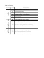
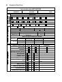
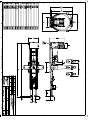
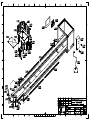
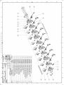
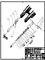
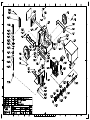
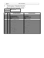
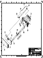
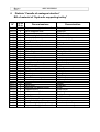
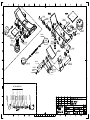
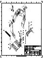
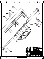
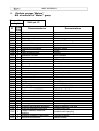
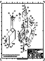
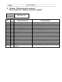
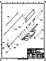
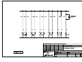
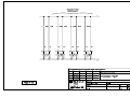
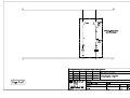
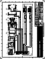
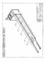
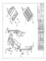
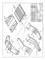
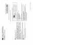
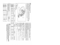
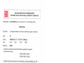
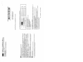
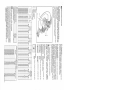
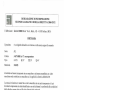
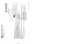
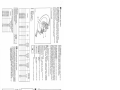
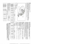
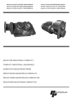
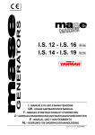
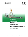
This document is the property of MAUS ITALIA. Any reproduction, even partial, is forbidden. File: MEF-TIM_092.doc Table of contents DESCRIPTION Manufacturer & Assistance Service A2 Equipment Data Sheet A3 General Arrangement Drawing A4 Exploded Drawings & Bill of Materials A5 Wiring Diagram A6 Hydraulic Diagram B6 Factory Acceptance Test & Reports B7 Conformity Declaration C8 Main Raw & Welds (identification / certificates) D9 Main Components Manuals & Certificates B FAT A Drawings A1 C Raw & Welds PART D Brochures SECTION A1. Manufacturer & Assistance Service Costruttore & Servizio Assistenza 1.1 Manufacturer: MAUS Italia F.Agostino & C S.a.s. SS. Paullese Km 30 26010 Bagnolo Cremasco (CR) ITALY www.mausitalia.it 1.2 Assistance Service: MAUS Italia F.Agostino & C S.a.s. SS. Paullese Km 30 26010 Bagnolo Cremasco (CR) ITALY Tel. +39 0373 237001 Fax +39 0373 649560 E-mail [email protected] A2. Equipment Data Sheet Machine: Tube bundles puller MEF-EXPRESS Model: Serial number: 2200/80 D Year of Construction: 2010 092 2010 Rocker Arm Size: - 1300 - 1600 - 1700 - 2000 - 2200 - 2500 - - 15 - 22 - 35 - 45 - 65 - Capacity (Ton): - 10 Frame - 6500 - 7500 Liquid Manufacturer: - Air - 8000 cooled - Engine Model: YANMAR - 12500 Power: 3TNE88-BDYE Serial No. 38 Hp C2982 28 Kw Gear Pumps model and capacity Model: Manufacturer: MARZOCCHI Displacement: GHP2HL-D-25/40-3/1-80-P606 27/02/2010 Serial No. 25 Cm3/rev Main carriage components and data Manufacturer: Hydraulic Motor SAMHYDRAULIK 1st - Reducer PIVPOSIPLAN Thrust / pulling force 650 KN Model: HT 400 D C40 Serial No.: 0705-212133 PH325K/46.7/00 100029810 2nd - Reducer Support Trolleys Type First Second Additional Mechanical Hydraulic Hydraulic Double Cylinder SS Protection - No - Yes Chalwyn valve - No - Yes Re-filling Diesel Pump - No - Yes Hydraulically extended arm - No - Yes Fixed Extension - No - Yes Radio Control - No - Yes Telescopic Extension - No - Yes Instrumentation - No - Yes Additional Rocker Arm - No - Yes Stroke: Length: Length: Size/Capacity: A3. General Arrangement Drawing Disegno Complessivo A4. Exploded Drawings & Bill of Materials Disegni Esplosi e Distinte Materiali 1 Distinta gruppo “Binario principale”e “Blocco di appoggio” Bill of material of “Main frame” and “Plate bearing” Disegno N° Drawing N° N° 1240 1241 1246 1247 1248 1249 1251 1252 1253 1254 1255 1256 1257 1258 1259 1260 1270 1272 1273 1275 1277 1281 1282 1288 1289 1290 1291 1292 1293 1294 1295 1296 Q.tà Q.ty 2 2 4 4 2 6 2 1 2 1 1 1 1 1 19 19 1 4 1 4 4 1 1 1 1 1 1 1 4 1 1 1 8018 part. G1-2 Denominazione Puleggia cavo ancoraggio Seeger Ø50mm Vite fissaggio blocco finecorsa Blocco finecorsa Cremagliera anteriore Cremagliera centrale Cremagliera posteriore Telaio Sportello laterale sinistro Sportello laterale destro Telaio vano motore Sportello frontale destro Sportello frontale sinistro Sportello superiore Dado autobloccante Vite cerniera Staffa guida cavo Sx Rondella elastica Supporto frontale di reazione (sx) Dado fissaggio blocco finecorsa Vite fissaggio staffa Copertura comandi manuali Distributore idraulico Sportello laterare sinistro Sportello posteriore Sx Sportello posteriore dx telecomando Selettore comandi Pulsante emergenza Quadro elettrico Staffa guida cavo Dx Supporto frontale di reazione (dx) Denomination Anchoring rope pulley Seeger Ø50mm End-stroke block fixingscrew End-stroke block Front rack Middle rack Rear rack Frame Left lateral door Right lateral door Motor case frame Right frontal door Left frontal door Upper door Self-locking nut Hinge screw Raceway bracket left Spring washer Front reaction support (Left) End-stroke block fixing nut Raceway bracket screw Manual controls cover Hydraulic distributor Left lateral door Rear panel left Rear panel right Remote control Comand selector Emergency push-button Electrical cabinet Raceway bracket right Front reaction support (Right) MEF EXPRESS 2 Distinta gruppo “Distributore” Bill of material of “Distributor” Disegno N° Drawing N° 2.282 part. G1 MEF EXPRESS 3 Distinta gruppo “Cilindro idraulico di ancoraggio” Bill of material of “Anchoring hydraulic cylinder” Disegno N° Drawing N° 7989 part. G3 N° Q.tà Q.ty Denominazione 3.184 3.186 3.187 3.188 3.189 3.190 3.191 3.193 3.196 3.199 3.200 3.201 3.202 3.203 3.204 3.205 2 2 2 2 2 4 2 2 2 2 2 2 2 2 2 2 Staffa Guida cromata Controdado Flangia cuscinetto Bussola a ricircolo di sfere Vite fissaggio flangia cuscinetto Stelo cromato Flangia cilindro idraulico Flangia pistone Pistone Dado autobloccante Cilindro Perno fissaggio cilindro idraulico Rondella elastica Vite fissaggio perno Kit Guarnizioni cilindro ancoraggio Denomination Braket Chromium plated guide Locknut Ball bearing flange Ball bushing Ball bearing flange fixing screw Chromiumplatedrod Hydraulic cylinderflange Piston flange Piston Self lockring nut Cylinder Hydraulic cylinder hinge pin Spring washer Hinge pin fixing screw Seal kit for Anchoring cylinder 3.189 3.188 3.187 3.202 3.186 3.203 3.204 3.184 3.201 3.200 3.199 3.205 3.190 3.205 3.196 3.205 3.205 3.193 3.205 3.205 3.191 MEF EXPRESS 4 Distinta gruppo “Carro estrattore” Bill of material of “Puller trolley” Disegno N° Drawing N° N° Q.tà Q.ty 4.57 4.59 4.65 4.66 4.67 4.68 4.69 4.70 4.71 4.72 4.73 4.74 4.78 4.79 4.81 4.82 4.83 1 1 1 1 4 4 4 4 1 11 11 1 2 2 2 2 4 4.84 4.88 4.89 4.90 4.91 4.92 4.93 4.94 4.95 4.96 4.97 4.98 4.110 4.111 4.112 4.113 4.114 4.117 4.118 4.119 4.120 4.121 1 2 1 10 12 2 1 4 1 2 2 2 4 4 1 2 6 1 4 4 1 4 8018 part. G4 Denominazione Seeger Bussola di guida spintore Telaio carrello Avvolgitubo a 3 vie Rondella elastica Vite fissaggio avvolgitubo 3 vie Vite carter destro Rondella Carter destro Vite cartersuperiore Rondella Carter superiore Cuscinetto Bussola Rondella Vite Cuscinetto di strisciamento, mensola di ancoraggio Mensola di ancoraggio Vite cuscinetto a strisciamento Cuscinetto aggancio Vite fissaggio gancio carrello Vite cuscinetto superiore Cuscinetto superiore Avvolgitubo a 3 vie Rondella elastica Avvolgitubo a 2 vie Gancio carrello Distanziale Seeger Vite carter sinistro Rondella Carter sinistro Cuscinetto a strisciamento anteriore Vite cuscinetto a strisciamento anteriore Supporto fine-corsa idraulico Vite Dado Finecorsa idraulico Vite Denomination Seeger Pusher Guide Trolley frame 3 ways tube-coiler Spring washer 3 ways tube-coiler fixing screw Right case fixing screw Washer Right case Uppercasescrew Washer Upper case Bearing Bush Washer Screw Anchoring bracket, plain bearing Anchoring bracket Plain bearing screw Anchoring plain bearing Screw Upper plain bearing screw Upper plain bearing 3 ways tube-coiler Spring washer 2 ways tube-coiler Trolley hook Spacer Seeger Leftt case fixing screw Washer Left case Front plain bearing Front plain bearing screw Hydraulic end-stroke support Screw Nut Hydraulic end-stroke Screw MEF EXPRESS 4.122 4.123 4.124 4.125 4.126 4.127 4.128 4.129 4.130 4.131 4.132 4.133 4.134 4.135 4.136 4.137 4.138 4.139 4n.59 4n.62 4n.63 1 1 1 1 2 2 2 2 2 2 2 2 2 2 1 1 1 1 1 4 2 4n.85 1 4n.86 4n.87 4n.99 1 1 2 Spintore regolabile Distanziale Spina regolazione spintore Albero motrice Linguetta riduttore Linguetta pignone Anello elastico cuscinetto Cuscinetto supporto Supporto cuscinetto Distanziale pignone Coperchio supporto Anello Pignone albero motrice Anello elastico pignone Motore idraulico Attacco posteriore riduttore Attacco anteriore riduttore Riduttore Cilindro sinistro Seeger Perno fissaggio cilindro mensola di ancoraggio Perno fissaggio cilindri mensola di ancoraggio Dado Vite fissaggio perno Snodo cilindro piastra ancoraggio 4n.100 4n.102 4n.105 4n.107 4n.109 4n.110 4n.115 2 2 2 2 2 1 1 Stelo cilindro idraulico Bussola di guida Porta guarnizione anteriore Porta guarnizione Dado autobloccante Kit guarnizioni cilindro Cilindro destro Adjustable pusher Spacer Pusher adjusting pin Main shaft Key reductor Key pinion Bearing elestic ring Bearing Bearing holder Pinion specer Cover Ring Main shaft pinion Elastic ring Hydraulic motor Back stirrup gear Front stirrup gear Gear reductor Left cylinder Seeger Anchoring bracket hydraulic cylinder fixing pin Anchoring plain hydraulic cylinder fixing pin Nut Pin fixing screw Anchoring braket hydraulic cylinder ball-joint Hydraulic cylinder piston rod Guide bush Front gasket holder Gasket holder Locknut Cylinder Seals kit Right cylinder MEF EXPRESS 5 Distinta gruppo “Spingitore idraulico” Bill of material of “Hydraulic pusher ” Disegno N° Drawing N° N° 1 2 3 4 5 6 7 8 9 10 11 12 13 14 15 16 17 18 19 Q.tà Q.ty 1 1 6 2 4 2 2 2 2 2 2 4 8 1 4 4 4 2 2 9646 part. G4 Denominazione Piastra anteriore Tampone anteriore Vite tampone anteriore Albero Perno fissaggio pistone Boccola in teflon Seeger Anello di spallamento Boccola in teflon Asta Pistone telescopico Tubo idraulico Seeger Telaio spingitore Perno fissaggio aste Rondella vite telaio Vite fissaggio telaio Boccola in teflon Grano con sfera Denomination Front plate Front buffer Screw front buffer Shaft Piston pin fixing Teflon bush Seeger Shoulder ring Teflon bush Rod Telescopic piston Hydraulic tube Seeger Pusher frame Pin fixation rod Washer Frame fixing screw Teflon bush Corn ball MEF EXPRESS 6 Distinta “Carrello di sostegno idraulico” Bill of material of “Hydraulic supporting trolley” N° Q.tà Q.ty Denominazione 5b.117 5b.118 5b.119 5b.120 5b.121 5b.122 5b.123 5b.124 5b.125 5b.127 5b.128 5b.130 5b.136 5b.137 5b.138 5b.140 5b.141 5b.142 5b.143 5b.145 5b.146 5b.147 5b.149 5b.150 5b.151 5b.153 5b.154 5b.155 5b.156 5b.157 5b.158 5b.159 5b.160 5b.161 5b.162 1 4 4 1 8 1 16 8 4 2 2 2 2 2 2 4 8 38 1 2 3 6 4 4 22 8 2 8 2 2 4 2 1 1 1 Copertura avvolgitubo I carrellino Perno superiore leva Pala carrellino Staffa avvolgitubo I carrellino Perno rullo contenimento Avvolgitubo I carrellino Cuscinetto rullo contenimento Rullo contenimento Spazzola con battuta corta Ingrassino Stelo cilindro carrellino Guida in Ghisa Pistone Dado autobloccante Camicia cilindro Maniglia carrellino Rullo appoggio carrellino Cuscinetto rullo Collegamento bilanciatori Telaio carrellino Bilanciatore a molla Perno cilindro Leva DX Perno superiore cilindro Seeger Perno rullo Spazzola con battuta lunga Copertura rullo Kit Guarnizioni cilindro Copertura carrellino Leva SX Spazzola semplice Avvolgitubo II carrellino Staffa avvolgitubo II carrellino Copertura avvolgitubo II carrellino Denomination Coverage hoses reels Upper pin Blade carriage Bracket Pin roller containment Hoses reels I trolley Bearing Roller containment Brush Wheat greasing Trolley cylinder rod driving Piston Nut Cylinder sleeve Handle trolley Support roller Bearing Balancers connection Trolley frame Spring balancer Cylinder pin Right lever Upper cylinder pin Seeger Roller pin Brush Roller cover Gasket git Trolley coverage Left lever Brush Hosese reels Hose bracket trolley Hoses reels coverage 5b.153 5b.142 5b.120 5b.141 5b.157 5b.122 5b.154 5b.146 5b.146 5b.162 5b.121 5b.161 5b.123 5b.159 5b.124 5b.160 5b.155 5b.119 5b.143 5b.125 5b.138 5b.118 5b.146 5b.147 5b.150 5b.149 5b.151 5b.158 5b.138 5b.137 O-RING PISTONE 5b.136 Guarnizione pistone EGR 1100 5b.156 5b.156 5b.156 ANELLO ANTIESTRUSIONE O-RING GUIDA 5b.156 5b.156 5b.130 GUARNIZIONE STELO 5b.156 5b.156 5b.128 5b.127 RASCHIATORE KIT GUARNIZIONI MEF EXPRESS 7 Distinta “Bilanciere” Bill of material of “Balancer” Disegno N° Drawing N° N° 6.157 6.159 6.161 6.162 6.163 6.164 6.165 6.166 6.168 6.169 6.170 6.171 6.172 6.174 6.175 6.176 6.177 6.178 6.179 6.180 6.181 6.182 6.183 6.184 6.185 6.186 6.187 Q.tà Q.ty 2 1 1 4 8 14 8 4 8 4 6 / 1 2 4 4 1 4 2 4 2 4 1 2 4 4 4 7989 part. G6 Denominazione Grillo zincato Campanella Testa bilanciere circolare Dado rullo Vite gancio piastra Rondella Vite bloccaggio protezione anello Piastra bloccaggio HEB Rondella Distanziale piastre HEB Vite piastra di bilanciamento Rondella Piastra d'attacco cilindri bilanciamento Perno stelo cilindro Rondella Spinotto bilanciere Piastra di base Perno bilanciere Cuscinetto di base (teflhon) Rullo guida Fermo perno stelo Vite fermo perno stelo Protezione centrale anello Parete anello Spina bloccaggio perno Perno parete laterale Ghiera di bloccaggio perno Denomination Bow Master link Head Nut Screw hook plate Washer Lock screw HEB plate Washer HEB spacer Screw balance plate Washer Coupling plate cylinders balance Pivot rod cylinder Washer Balancer pin Base plate Balancer pin Base bearing Roller guide Block pivot rod Lock screw Protection central ring Wall ring Locking pin plug Pin side wall Nut locking pin 6,159 6,186 6,185 6,184 6,157 6,161 6,184 6,186 6,187 MEF EXPRESS 8 Distinta “Cilindro idraulico di bilanciamento” Bill of material of “Balancing hydraulic cylinder” Disegno N° Drawing N° N° 6f.205 6f.206 6f.207 6f.208 6f.209 6f.210 6f.211 6f.212 6f.213 6f.214 6f.217 6f.220 6f.222 6f.223 6f.224 6f.225 Q.tà Q.ty 2 2 2 2 2 2 2 2 2 2 2 2 2 4 2 2 7989 part. G6f Denominazione Vite staffa Staffa cilindro idraulico Rondella elastica Dado Vite perno cilindro idraulico Rondella Perno cilindro Cilindro idraulico Dado autobloccante Pistone Flangia pistone Flangia cilindro idraulico Stelo pistone Vite snodo stelo Snodo stelo cilindro idraulico Kit Guarnizioni Denomination Braket screw Hydraulic cylinder braket Spring washer Nut Hydraulic cylinder hinge pin screw Washer Hydraulic cylinder hinge pin Hydraulic cylinder Self lockring nut Piston Piston flange Hydrayulic cyllinder flange Piston rod Ball joint pin screw Piston rod ball joint Gasket kit MEF EXPRESS 9 Distinta gruppo “Motore” Bill of material of “Motor” group Disegno N° Drawing N° N° Q.tà Q.ty 7281 7282 7283 7284 7285 7286 7287 7288 7289 7290 7291 7292 7293 7294 7300 7301 7302 7303 7304 7305 7306 7307 7308 7309 7310 7311 7323 7324 7325 7326 7329 7331 7332 7333 7334 2 1 4 4 1 4 1 1 4 4 1 2 2 1 1 1 1 1 1 1 5 1 1 8 1 1 1 4 1 1 4 1 1 4 1 7335 1 7336 7337 1 1 7989 part. G7 Denominazione Vite Silenziatore Vite Supporto antivibrante Motore Diesel Lombardini Dado autobloccante Serbatoio centralina idraulica Guarnizione indicatore Vite Dado autobloccante Indicatore di livello Supporto motore Vite indicatore Vite Tubo sfogo aria Piastra accumulatore Vite accumulatore Accumulatore Cavo polo positivo Cavo polo negativo Dado Tappo serbatoio Flangia serbatoio Vite flangia serbatoio Filtro grande Supporto filtro grande Tappo serbatoio DIESEL Vite Filtro carburante Serbatoio carburante Vite Dado base supporto serbatoio Supporto antivibrante serbatoio Rubinetto serbatoio idraulico Tappo Rubinetto serbatoio idraulico Supporto serbatoio carburante Raccordo silenziatore Denomination Screw Silencer Screw Vibration-damper Lombardini Diesel engine Locknut Hydraulic unit tank Indicator gasket Screw Locknut Level indicator Engine support Indicatorscrew Screw Air blowdown tube Accumulator plate Accumulatorscrew Accumulator Positive pole cable Negative pole cable Nut Tankcap Tank flange Tank flange screw Hydraulic oil filter (big) Filter support (big) DIESEL Fuel Tank plug Screw Fuel filter Fuel tank Screw Nut Fuel tank support base Vibration-damper Fuel tank Hydraulic tank tap Hydraulic tank tap plug Fuel tank support Silencer braket MEF EXPRESS 10 Distinta “Cilindro idraulico tenditore” Bill of material of “Tightener hydraulic cylinder” Disegno N° Drawing N° N° Q.tà Q.ty 11225 11226 11227 11228 11229 11230 11231 11232 11233 11234 11235 11238 11239 11242 11244 11245 1 2 2 1 2 1 1 2 2 2 1 2 2 2 2 2 11246 2 7989 part. G11 Denominazione Cavo ancoraggio L=6,5mt Spina di sicurezza Ghiera forcella Cavo ancoraggio L=8mt Dado autobloccante Cilindro idraulico destro Cilindro idraulico sinstro Staffa cilindro idraulico Vite staffa Dado autobloccante Pistone Flangia pistone Stelo pistone Flangia cilindro idraulico Perno Forcella Kit Guarnizioni cilindro tendicavo Denomination Anchoring rope L=6,5mt Safetypin Braket lockring Anchoring rope L=8mt Self lockring nut Right hydraulic cylinder Left hydraulic cylinder Hydraulic cylinder braket Braket screw Self lockring nut Piston Piston flange Pistonrod Hydraulic cylinder flange Gudgeon Fork Gasket kit for Tightener Cylinder MEF EXPRESS A5. Wiring Diagram Schema Elettrico MEF EXPRESS A6. Hydraulic Diagram Schema Idraulico MEF EXPRESS B6. Inspection & Test Reports Certificati di ispezione/collaudo Codice istruzione collaudo: Test Istruction Code:: Stato approvazione e validità documento emesso. Progetto: IMC 06-0 MEF Item: Stesura: Drawn: (UT) A.Bettinelli Verificato: Checked: (AQ) Data : Date : 27/01/2009 Data : Date : 1 Rev. : Approvato: Approved: (DG) 27/01/2009 Data : Date : 27/01/2009 RAPPORTO DI COLLAUDO N° 06-0-092 Testing report Modello: Model: Matricola MEF EXPRESS 2200 / 80 D Cliente: Customer: PEMEX N° Controlli e collaudi eseguiti Anno costruzione: Serial No. 2010 Manufacture year: Controllo visivo & dimensionale Visual & dimensional 2 Funzionamento impianto pneumatico Pneumatic plant 3 Funzionamento impianto elettrico Electrical plant 3 Funzionamento impianto idraulico Hydraulic plant 4 Funzionamento emergenze Emergency 5 Documentazione tecnica Technical documentation 6 Imballaggio Packing 7 Marcatura e matricola Serial number and “CE” marking 8 Altri – Others: Internal order: N° 10/5926 Positivo Positive Inspection & test report 1 N° 2010 / 092 Commessa : Negativo Negative Note Notes Note - Notes:………………………………………………………………………………………………………………………………….. Esito: Test: Eseguito da: Executed by: Esito: Test: Isp./cliente: Inspec./cust. Positivo / Positive Negativo / Negative Data: Date: Positivo / Positive Firma : Signature : Negativo / Negative Data: Date: - Note / Notes - ............................... Note / Notes Firma : Signature: ……………………….. BENESTARE ALLA SPEDIZIONE Shi p me n t A p p r o val N° 1 2 3 4 5 Controlli Inspections Verifica integrità della macchina dopo collaudo positivo. Verifica integrità / correttezza delle marcature sulla macchina e sull’imballo. Verifica disponibilità della documentazione prevista per tipo di macchina. Dichiarazione di conformità compilata e firmata (Mod.503). Manuale d’istruzione uso e manutenzione. Eventuale documentazione tecnica aggiuntiva prevista per la macchina. Copia firmata e data del presente Rapporto di Collaudo (Mod. IMC-06-0). Verifica corrispondenza tra dati riportati sulla macchina e documenti di spedizione (bolla o conferma d’ordine). Verifica disponibilità della dotazione degli attrezzi, prevista per il tipo di macchina. Eseguito da: Executed by: IMC 06-0-092.doc Data : Date : -1- Machine integrity check, after the testing. Check of integrity / correct marking on the machine and on the packing. Verification availability of the previewed documentation: Declaration of conformity filled in and signed. Instruction of operating & maintenance manual. Any additional technical documentation Signed copy of the present testing report. Verification of the correspondance between shipping documents (freight bill, order confirmation), and the machine specifications. Check of the tools provide for the type of the machine. Firma : Signature : Codice istruzione collaudo: Test Istruction Code:: Stato approvazione e validità documento emesso. Fase 1 C1 2 C2 3 C3 B C B C Stesura: Drawn: (UT) A.Bettinelli Verificato: Checked: (AQ) Data : Date : 27/01/2009 Data : Date : MEF Rev. : 1 Approvato: Approved: (DG) Data : Date : 27/01/2009 27/01/2009 ASSEMBLY INSTRUCTURE Preparazione preliminare Pulire accuratamente tutta la macchina. Preliminary preparation Clean the machine Verify that the machine is clean Verificare il grado di pulizia della macchina. Applicazione targhette Applicare targhette di identificazione e marcatura CE. Plates application Apply plates whit code and CE Verificare applicazione targhette. Verify plates application Montaggio dinamometro. Rimuovere i blocchi fine corsa all’estremità anteriore del telaio. Fissare il dinamometro al telaio con le apposite staffe. Dynamometer assembly Remove the End excursion block in the front side Fix the dynamometer on the case Verificare il corretto tiraggio delle viti di fissaggio del dinamometro. Verify the correct torque value of the dynamometer fixing screw ISTRUZIONI DI COLLAUDO TEST INSTRUCTION Preparazione Avviare la macchina. Portare nella zona anteriore della macchina il carro estrattore. Posizionare la fune di tiro tra carro estrattore ed i golfari del dinamometro. Verifica funzionale Agire sulla leva dell’acceleratore del motore e portare il motore a pieno regime. Azionare il comando del carro estrattore tendere la fune gradualmente. Proseguire la prova di tiro e leggere il valore massimo indicato sul manometro. Rilasciare il comando del carro estrattore. Verificare il funzionamento e la corsa di tutti gli attuatori. Verifica finale Smontare la fune di tiro. Spegnere la macchina. Verificare l’assenza di trafilamenti di olio dai raccordi. Verificare la presenza di eventuali deformazioni a seguito della prova. Fase A Item: ISTRUZIONI DI MONTAGGIO Fase A Progetto: IMC 06-0 ISTRUZIONI DI IMBALLAGGIO Preparation Start the machine Move the extractor trolley in the front part Put the tightener cable between the extractor trolley and the dynamometer Functional test Set the Engine control in the “Full Throttle” position. Tight the cable step by step up to the maximum force valued read on the dynamometer. Release the cable. Check the functionality and the excursion of all actuators Final test Remove the cable Switch-off the machine Verify no oil leakage Verify no structural deformation after the test Positivo Negativo Note Positivo Negativo Note Positivo Negativo Note PACKING INSTRUCTION Controllo visivo Verificare l’integrità dell’imballaggio. Visual check Verify the packaging integrity Preparazione Bilanciare la macchina. Svuotare il serbatoio centralina Bloccare i carrelli di supporto nella parte anteriore della macchina. Imballare gli accessori e la documentazione tecnica previsti e fissarli sulla macchina. Preparation Balance the machine Empty hydraulic unit tank Lock the support trolley in front position Pack the supplementary tools and technical documentation Imballaggio Packaging Proteggere le parti non verniciate della macchina con grasso. Preserve the no paint parts with grease. Avvolgere la macchina con telo di plastica e/o nastro termoretraibile; in Wrap the machine with plastic length or put it into wood crate. alternativa posizionare la macchina in cassa di legno con sacco barriera. NOTE: ……………………………………………………………………………………………………………………………………… ……………………………………………………………………………………………………………………………………… ……………………………………………………………………………………………………………………………………… ……………………………………………………………………………………………………………………………………… ……………………………………………………………………………………………………………………………………… IMC 06-0-092.doc -2- MEF EXPRESS B7. Conformity Declaration Dichiarazione di conformità CE DECLARATION OF CONFORMITY (prepared pursuant to paragraph A of Annex II of Directive 2006/42/EC and subsequent amendments and / or additions) CORPORATE NAME MAUS Italia F. Agostino C. S.a.s ADDRESS SS. Paullese Km.30 26010 Bagnolo Cremasco (CR) (Italia) TELEPHONE NUMBER +39 0373 237001 FAX NUMBER +39 0373 649560 as a manufacturer of the equipment hereafter: TYPE SERIAL NUMBE YEAR OF MANUFACTURE MEF EXPRESS 2200/80 D 2010/092 2010 STATES UNDER THE RESPONSIBILITY THAT THE MACHINE, AS DESCRIBED IN THE DOCUMENTATION ATTACHED AND IN OUR ARCHIVES: It is a machine according to and on to the effects of Directive 2006/42/EC and subsequent amendments and / or additions and the same CE marking was affixed; It Conforms to the following European Directives and standards (normative references are to be applied also to any subsequent amendments and / or additions): Machinery Directive 2006/42/EC and European standards EN ISO 12100-1, EN ISO 12100-2, UNI EN ISO 13857th, UNI EN 349, UNI EN ISO 13850, UNI EN ISO 14121-1, UNI EN ISO 13849-1 and CEN 60204-1:2006. Directive 2004CE/108/CE - Electromagnetic Compatibility Directive 2006/95/EC - Low voltage and the European standard CEN 60204-1:2006. The person authorized to represent the technical dossier is Eng. Stefano Agostino, as GENERAL MANAGER of MAUS Italy Sas, domiciled at MAUS Italy Sas - SS. Paullese Km 30, 26010 Bagnolo Cremasco (CR). NAME AND SURNAME Ing. Stefano Agostino JOB POSITION General Manager Date Signature Mod. 503-r5_uk MEF EXPRESS C8. Main Raw & Welds (identification / certificates). Certificati Acciai & Saldature parti principali. MEF EXPRESS 8.1. Main frame parts identification / certificates Certificati Acciai telaio estrattore MEF EXPRESS 8.2. Rocker arm parts identification / certificates Certificati Acciai bilanciere MEF EXPRESS 8.3. WPS Wps MEF EXPRESS D9. Main Components Manuals & Certificates. 9.1. Engine Motore 9.2. Hoses reels Avvolgi tubi 9.3. Master link Campanella di sollevamento 9.4. Bow Shackle Grillo ad omega 9.5. Ropes Funi MEF EXPRESS 9.1 Engine Motore MEF EXPRESS 9.2 Hose reels Avvolgi tubi MEF EXPRESS 9.3 Master link Campanella di sollevamento MEF EXPRESS 9.4 Bow Shackle Grillo ad omega MEF EXPRESS 9.5 Ropes Funi