1
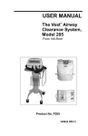
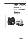
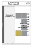
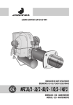
Gentile Cliente,
I
La ringraziamo per aver preferito uno dei nostri prodotti, frutto di esperienza pluriennale e di una continua ricerca per una
qualità superiore in termini di sicurezza, affidabilità e prestazioni.
In questo manuale troverà tutte le informazioni ed i consigli utili per poter utilizzare il suo prodotto nel massimo della
sicurezza ed efficienza.
!
Le ricordiamo che la prima accensione deve essere effettuata dal nostro Centro Assistenza Autorizzato (Legge 37/2008)
che verifichi l’installazione e compili la garanzia.
• Installazioni scorrette, manutenzioni non correttamente effettuate, uso improprio del prodotto sollevano l’azienda
produttrice da ogni eventuale danno derivante dall’uso della stufa.
• L’apparecchio non deve essere usato come inceneritore, nè devono essere utilizzati combustibili diversi
dal pellet.
• Questo manuale è stato redatto dal costruttore e costituisce parte integrante del prodotto e deve accompagnarlo
durante tutta la sua vita. In caso di vendita o trasferimento del prodotto assicurarsi sempre della presenza del
libretto poichè le informazioni in esso contenute sono indirizzate all’acquirente, e a tutte quelle persone che a vario
titolo concorrono all’installazione, all’uso e alla manutenzione.
• Leggete con attenzione le istruzioni e le informazioni tecniche contenute in questo manuale, prima di procedere all’installazione, all’utilizzo e a qualsiasi intervento sul prodotto.
• L’osservanza delle indicazioni contenute nel presente manuale garantisce la sicurezza dell’uomo e del prodotto,
l’economia di esercizio ed una più lunga durata di funzionamento.
• L’attenta progettazione e l’analisi dei rischi fatti dalla nostra azienda hanno permesso la realizzazione di un prodotto sicuro; tuttavia prima di effettuare qualsiasi operazione, si raccomanda di attenersi scrupolosamente alle istruzioni
riportate nel seguente documento e di tenerlo sempre a disposizione.
• Fare molta attenzione nel movimentare i particolari in ceramica dove presenti.
• Controllare l’esatta planarità del pavimento dove verrà installato il prodotto.
• La parete dove va posizionato il prodotto non deve essere di legno o comunque di materiale infiammabile,
inoltre è necessario mantenere le distanze di sicurezza.
• Durante il funzionamento, alcune parti della stufa (porta, maniglia, fianchi) possono raggiungere temperature elevate. Fate dunque molta attenzione ed usate le dovute precauzioni, soprattutto in presenza di bambini, persone
anziane, disabili e animali.
• Il montaggio deve essere eseguito da persone autorizzate (Centro Assistenza Autorizzato).
• Schemi e disegni sono forniti a scopo esemplificativo; il costruttore nell’intento di perseguire una politica di costante
sviluppo e rinnovamento del prodotto può apportare, senza preavviso alcuno, le modifiche che riterrà opportune.
• Si raccomanda, alla massima potenza di funzionamento della stufa, l’utilizzo di guanti per maneggiare sportello
caricamento pellet e maniglia per l’apertura della porta.
• È sconsigliata l’installazione in camera da letto.
!
Mai coprire in alcun modo il corpo della stufa o occludere le
feritoie poste sul lato superiore quando l’apparecchio è in funzione. A tutte le ns. stufe viene provata l’accensione in linea.
In caso d’incendio disinserire l’alimentazione elettrica, utilizzare un estintore a norma ed eventualmente
chiamare i Vigili del Fuoco. Contattare poi il Centro Assistenza Autorizzato.
1
I
1.0 Normative e dichiarazione di conformità
La nostra azienda dichiara che la stufa è conforme alle seguenti norme per la marcatura CE Direttiva Europea:
• 89/336 CE e 2004/108 CE (direttiva EMC) e successivi emendamenti;
• 2006/95 CE (direttiva bassa tensione) e successivi emendamenti;
• 2006/42 CE (direttiva macchine);
• 89/106 CE (prodotti da costruzione);
• Per l’installazione in Italia fare riferimento alla UNI 10683/98 o successive modifiche e per l’impianto idrotermosanitario
farsi rilasciare da chi ha eseguito l’impianto la dichiarazione di conformità secondo L. 37/2008. Tutte le leggi locali e
nazionali e le norme europee devono essere soddisfatte nell’installazione dell’apparecchio;
• EN 60335-1; EN 50165; EN 50366; EN 55014-1; EN 61000-3-2; EN 61000-3-3; EN 14785.
1.1 Informazioni sulla sicurezza
Si prega di leggere attentamente questo manuale d’uso e manutenzione prima di installare e mettere in funzione la stufa!
In caso di chiarimenti, rivolgersi al rivenditore o al Centro Assistenza Autorizzato.
• La stufa a pellet deve funzionare solamente in ambiente abitativi. Questa stufa essendo comandata da una scheda elettronica
permette una combustione completamente automatica e controllata; la centralina regola infatti la fase d’accensione, 5 livelli di
potenza e la fase di spegnimento, garantendo un funzionamento sicuro della stufa;
• Il cestello impiegato per la combustione fa cadere nel cassetto di raccolta gran parte della cenere prodotta dalla combustione dei pellet. Controllare comunque quotidianamente il cestello, dato che non tutti i pellet hanno standard qualitativi
alti (usare solo pellet di qualità consigliato dal costruttore);
• Il vetro è dotato di uno speciale giro d’aria per l’autopulizia dello stesso tuttavia non è possibile evitare una leggera patina grigiastra
sul vetro dopo alcune ore di funzionamento. Ciò dipende anche dal tipo di pellet usato. Alcuni pellet possono sporcare più di altri.
1.2 Responsabilità
Con la consegna del presente manuale, decliniamo ogni responsabilità, sia civile che penale, per incidenti derivati dalla non
osservanza parziale o totale delle istruzioni in esso contenute.
Decliniamo ogni responsabilità derivante dall’uso improprio della stufa, dall’uso non corretto da parte dell’utilizzatore, da
modifiche e/o riparazioni non autorizzate, dall’utilizzo di ricambi non originali per questo modello.
Il costruttore declina ogni responsabilità civile o penale diretta o indiretta dovuta a:
• Scarsa manutenzione;
• Inosservanza delle istruzioni contenute nel manuale;
• Uso non conforme alle direttive di sicurezza;
• Installazione non conforme alle normative vigenti nel paese;
• Installazione da parte del personale non qualificato e non addestrato;
• Modifiche e riparazioni non autorizzate dal costruttore;
• Utilizzo di ricambi non originali;
• Eventi eccezionali.
!
2
• La stufa deve essere alimentata solo con pellet di qualità del
diametro di 6 mm del tipo raccomandato dal costruttore;
• Prima di collegare elettricamente la stufa, deve essere ultimata la connessione dei tubi di scarico con la canna fumaria;
• La griglia di protezione posta all’interno del serbatoio pellet non deve essere mai rimossa;
• Nell’ambiente in cui viene installata la stufa ci deve essere
sufficiente ricambio d’aria;
• Non aprire mai lo sportello della stufa durante il funzionamento della stessa;
!
I
• Quando la stufa è in funzione, c’è un forte surriscaldamento delle superfici, del vetro, della maniglia e delle tubazioni: durante il funzionamento, queste parti sono da toccare
con adeguate protezioni;
• Tenere/conservare il pellet in locali asciutti e non umidi;
• Tenere ad adeguata distanza di sicurezza della stufa sia il
combustibile sia eventuali materiali infiammabili.
2.0 Tasti funzione e display
Tasti funzione
1. Aumento di temperatura
Il pulsante consente di aumentare la temperatura da un minimo di 7°C al valore massimo di 40°C.
2. Diminuzione di temperatura
Il pulsante consente di diminuire il valore della temperatura da un massimo di 40°C al valore minimo di 7°C.
3. Pulsante di settaggio SET
Premere il pulsante per accedere al menù di programmazione della stufa.
4. ON/OFF
Tenere premuto il tasto per 2 secondi: la stufa si accende o si spegne.
5. Diminuzione della potenza
Il pulsante consente di diminuire il valore della potenza dal valore massimo di 5 al valore minimo di 1.
6. Aumento della potenza
Il pulsante consente di aumentare il valore della potenza dal valore minimo di 1 al valore massimo di 5.
2.1 Indicazioni display
7. Led cronotermostato
Indica che la programmazione settimanale e/o giornaliera è attiva.
8. Led funzionamento stufa “Smoke discharge”
È acceso quando la stufa è in funzione.
9-10. Display superiore/inferiore
Sul display vengono visualizzate le diverse modalità di funzionamento della stufa, nonchè la temperatura e la potenza di
lavoro impostata dall’utente.
Nel caso si verifichino malfunzionamenti della stufa, il display riporta le relative segnalazioni d’errore (vedi paragrafo “Casi
particolari”).
11. Ricevitore telecomando
Sensore di ricezione dei comandi impartiti dal telecomando.
12. Led set “Menu”
Il led è lampeggiante quando si imposta il valore di temperatura desiderato.
3
I
13. Led temperatura
Si accende quando è raggiunta la temperatura impostata. Sul display compare la scritta ECO.
14. Led ricezione telecomando
Il led è lampeggiante quando si utilizza il telecomando per modificare la temperatura e/o potenza.
15. Led pellet “Pellet”
Il led è lampeggiante ogni qualvolta è in corso il caricamento pellet all’interno della stufa.
Tasti funzione
Indicazioni display
1. Aumento della temperatura
2. Diminuzione della temperatura
3. Set menù
4. ON/OFF
5. Diminuzione della potenza
6. Aumento della potenza
7. Led cronotermostato
8. Led funzionamento stufa
9. Display superiore
10. Display inferiore
11. Ricevitore telecomando
12. Led set “Menu”
13. Led temperatura
14. Led ricezione telecomando
15. Led pellet
1
15
9
7
6
14
11
3
2
8
10
13
5
4
12
Fig. 1
Fig. 2
2.2 Descrizione telecomando (optional)
Il telecomando permette di controllare le seguenti
funzioni:
1. Aumento di temperatura:
1
3
2
4
+
Premendo il pulsante +
si aumenta la temperatura da
un valore minimo di 7°C a un valore massimo di 40°C.
2. Diminuzione di temperatura:
Premendo il pulsante si diminuisce la temperatura da
un valore massimo di 40°C a un valore minimo di 7°C.
3. Aumento di potenza:
Premendo il pulsante si aumenta la potenza da un
valore minimo di 1 a un valore massimo di 5.
4
Telecomando
1. Aumento di temperatura
2. Diminuzione di temperatura
3. Aumento di potenza
4. Diminuzione di potenza
I
4. Diminuzione di potenza:
Premendo il pulsante si diminuisce la potenza da un valore massimo di 5 a un valore minimo di 1.
5. Accensione e spegnimento:
Tenendo premuti contemporaneamente i tasti !
+
e
si accende o si spegne la stufa.
Le ricordiamo che la prima accensione deve essere effettuata dal nostro Centro Assistenza Autorizzato abilitato
(Legge 37/2008) che verifichi l’installazione e compili la
garanzia.
Durante la prima accensione occorre ventilare bene l’ambiente, potrebbero svilupparsi degli odori sgradevoli provenienti dalla vernice e dal grasso nel fascio tubiero.
2.3 Raccomandazioni
• Non accendere la stufa ad intermittenza: ciò può provocare scintille che possono abbreviare la durata dei componenti
elettrici;
• Non toccare la stufa con mani bagnate: la stufa avendo componenti elettrici, potrebbe provocare scariche, se maneggiata non correttamente. Solo i tecnici autorizzati possono risolvere possibili problemi;
• Non togliere nessuna vite dalla cassa del fuoco senza che sia stata prima ben lubrificata;
• Mai aprire la porta quando la stufa a pellet è in funzione;
• Assicurarsi che il cestello del braciere sia posizionato nella maniera corretta.
• Si ricorda che tutti i tratti del condotto fumi devono essere ispezionabili. Nel caso in cui sia fisso deve presentare aperture
d’ispezione per la pulizia.
2.4 Caricamento del pellet nel serbatoio
Il caricamento delpellet nel serbatoio avviene tramite l’apposito sportello posto nella parte superiore della stufa.
Per effettuare il caricamento procedere nel seguente modo:
• Aprire lo sportello presente su top superiore;
• Versare all’interno del serbatoio la quantità di pellet desiderata, prestando la dovuta attenzione (versare una quantità
sufficiente a garantire una discreta autonomia di funzionamento della stufa);
• Richiudere lo sportello.
3.0 Prima Accensione Stufa
3.1 Accensione stufa
• Riempire il serbatoio fino a 3/4 del pellet consigliato e raccomandato dalla casa costruttrice;
• Collegare la stufa ad una presa di corrente con l’apposito cavo in dotazione;
• Premere l’interruttore di accensione collocato nella parte posteriore della stufa;
• Sul display superiore compare la scritta “OFF” e su quello inferiore l’ora corrente;
• Premere il tasto
per 2 secondi. Dopo qualche istante si accendono l’estrattore fumi, la resistenza di accensione e
compare la scritta “FAN ACC”;
• Dopo circa 1 minuto compare la scritta “LOAD WOOD”, la stufa carica i pellets e continua l’accensione della resistenza;
• Una volta raggiunta la temperatura adeguata appare sul display la scritta “FIRE ON”: significa che la stufa è passata
all’ultima fase di accensione alla fine della quale sarà completamente operativa;
5
I
• Dopo qualche minuto sul display superiore compare la scritta “ON 1-2-3-4-5” a seconda della potenza impostata, mentre
nel display inferiore compare la temperatura ambiente;
• Nel caso del raggiungimento della temperatura impostata sul display superiore comparirà la scritta: “ECO” mentre nel
display inferiore compare la temperatura rilevata nell’ambiente;
• Il led temperatura si accende quando viene raggiunta la temperatura impostata;
• Prima dell’accensione accertarsi che il braciere sia vuoto da eventuali pellet e pulito dai residui di precedenti combustioni.
In caso contrario provvedere allo svuotamento e pulizia dello stesso;
!
ATTENZIONE!
Prima dell’accensione è possibile che un po’ di fumo riempia il vano di combustione.
3.2 Spegnimento stufa
Per spegnere la stufa premere il tasto
finchè sul display compare la scritta “OFF”. Anche dopo lo spegnimento della
stufa l’estrattore fumi continua a funzionare per un tempo prestabilito per garantire una rapida espulsione dei fumi dalla
camera di combustione.
4.0 Regolazione della stufa
!
ATTENZIONE:
è necessario effettuare la pulizia giornaliera del braciere e
periodica del cassetto cenere. La ridotta o mancata pulizia
può in alcuni casi provocare la mancata accensione della
stufa con conseguenti danni alla stufa e all’ambiente (possibili emissioni di incombusto e fuliggine).
Non reintrodurre il pellet eventualmente presente nel braciere per mancata accensione.
Modifica potenza
Può essere variato durante il lavoro della stufa tra un valore minimo di 1 ed un valore massimo di 5. Premendo il pulsante è possibile aumentare il valore, mentre premendo il pulsante è possibile diminuire tale valore. Il display indica il valore della potenza.
Modifica della temperatura
Il valore della temperatura può essere variato in ogni momento dall’utente. Per modificare la temperatura prima premere poi premere o
e selezionare il valore desiderato, tale valore è visualizzato sul display inferiore.
SET
4.1 Programmazione stufa - cronotermostato (optional)
Questa funzione permette di programmare due accensioni e due spegnimenti della stufa nell’arco della giornata o programmarla settimanalmente.
Per entrare nella programmazione:
• Premere 2 volte il tasto SET ;
• Selezionare i sottomenù (UT) premendo i tasti
e
.
UT01: Impostazione del giorno corrente e disinserimento cronotermostato.
Se il parametro UT01 è impostato con il giorno corrente ad esempio la domenica (Day 7) si seleziona il giorno della settimana a cui associare l’accensione PROGRAMMA 1 e/o PROGRAMMA 2.
6
I
4.2 Programmazione della stufa
Premendo i tasti
e
è possibile selezionare il valore desiderato.
Dicitura
Significato
Day 1
Day 2
Day 3
Day 4
Day 5
Day 6
Day 7
OFF
Lunedì
Martedì
Mercoledì
Giovedì
Venerdì
Sabato
Domenica
Cronotermostato disinserito
!
ATTENZIONE!
L’accesso alla funzione cronotermostato, quando la stufa
è in lavoro, comporta lo stop dell’orologio digitale all’interno della stufa per tutta la durata delle operazioni effettuate all’interno del menù. Si consiglia di agire nell menù
cronotermostato quando la stufa è in stand-by (OFF).
UT02: Impostazione ora.
Premendo nuovamente il tasto SET compare la scritta UT02 e nel display inferiore si visualizza l’ora corrente con puntini
lampeggianti. Regolare l’ora agendo sui tasti e
.
UT03: Premendo nuovamente il tasto SET compare la scritta UT03 e nel display inferiore si visualizzano i minuti con
puntini lampeggianti. Regolare i minuti agendo sui tasti e
.
UT04: Riservata al Centro Assistenza Autorizzato.
Premendo nuovamente il tasto SET compare la scritta UT04 riservata al tecnico.
Si consiglia di non modificarne i parametri impostati. Le modifiche a seguito di un accesso improprio richiedono l’intervento
NON IN GARANZIA di un tecnico autorizzato.
UT05: Indica l’orario d’inizio di lavoro del PROGRAMMA “1”. É possibile modificare l’orario ad intervalli di 10 minuti
agendo sui tasti e
.
N.B.: Questo parametro è attivo solo se UT01 è stato precedentemente impostato diverso da “OFF”.
UT06: Indica l’orario di fine lavoro del PROGRAMMA “1”. É possibile modificare l’orario ad intervalli di 10 minuti agendo
sui tasti
e
.
N.B.: Questo parametro è attivo solo se UT01 è stato precedentemente impostato diverso da “OFF”.
UT07:
Permette di selezionare il giorno della settimana a cui abbinare il PROGRAMMA “1”.
Con il pulsante si seleziona il giorno della settimana. Con il pulsante si attiva/disattiva l’accensione della
stufa. Nell’esempio l’accensione della stufa avviene nei giorni festivi di sabato e domenica.
Day 1
Lunedì
Off 1
Day 2
Martedì
Off 2
Day 3
Mercoledì
Off 3
Day 4
Giovedì
Off 4
Day 5
Venerdì
Off 5
Day 6
Sabato
On
Day 7
Domenica
On
7
I
UT08:
Indica l’orario d’inizio di lavoro del programma “2”. É possibile modificare l’orario ad intervalli di 10 minuti agendo sui
tasti
e
.
N.B.: Questo parametro è attivo solo se UT01 è stato precedentemente impostato diverso da “OFF”.
UT09: Indica l’orario di fine lavoro del PROGRAMMA “2”. É possibile modificare l’orario ad intervalli di 10 minuti agendo
sui tasti e
.
N.B.: Questo parametro è attivo solo se UT01 è stato precedentemente impostato diverso da “OFF”.
UT10: Permette di selezionare il giorno della settimana a cui abbinare il PROGRAMMA “2”.
Con il pulsante si seleziona il giorno della settimana. Con il pulsante si attiva/disattiva l’accensione.
ESEMPIO
Oggi è lunedì, vorrei accendere la stufa automaticamente il lunedì, il martedì, il giovedì e la domenica alle 8.00 del mattino,
e vorrei spegnerla alle ore 16.00. Il mercoledì, il venerdì e il sabato vorrei accenderla alle 9.00 e spegnerla alle 23.00.
!
ATTENZIONE!
Una volta impostati i programmi 1 e 2, il led Timer è acceso. Se i programmi 1 e 2 non sono stati programmati, il led
Timer rimane spento. Se viene a mancare l’erogazione di
corrente elettrica si avvia una batteria tampone che lascia
inalterate le impostazioni d’orario programmate.
Il programma sarà il seguente:
UT 01: day 1
UT 02: ora corrente
UT 03: minuti correnti
UT 04: riservato tecnici installatori
UT 05: 8.00
UT 06: 16.00
UT 07: On1-On2-Off3-On4-Off5-Off6-On7
UT 08: 9.00
UT 09: 23.00
UT 10: Off1-Off2-0n3-Off4-On5-On6-Off 7
!
ATTENZIONE!
La temperatura e la potenza alla quale funzionerà la stufa
nelle fasce d’orario con programmazione ON saranno quelle dell’ultimo spegnimento.
5.0 Informazioni sul display
“OFF”
“OFF” la stufa è spenta o si trova nella fase di spegnimento. Es: ora corrente 14:30.
8
I
“FAN - ACC”
La stufa è in fase di preriscaldamento resistenza, precede l’accensione.
“LOAD WOOD”
Segnala che la stufa è in fase di caricamento pellet.
“FIRE ON”
La stufa è in fase di stabilizzazione della fiamma (fiamma presente).
“ON 1”
La stufa è in fase di lavoro alla potenza minima. La temperatura rilevata nell’ambiente è di 29°C.
“ECO”
La stufa ha raggiunto la temperatura impostata dall’utente ed è in fase di risparmio ed economia. In
questa fase non è possibile modificare la potenza.
Se la temperatura impostata è di 41°C la stufa rimane sempre in funzione alla potenza
di lavoro impostata senza passare alla modalità economica (ECO).
“STOP FIRE”
La stufa è in fase di auto-pulizia del cestello; l’estrattore fumi gira alla massima velocità ed il carico
del pellet è al minimo (parametro non modificabile).
5.1 Casi particolari
La temperatura impostata deve essere superiore alla temperatura rilevata dalla sonda ambiente
(+/-1°C). In caso contrario comparirà la scritta “ON T”. In questo caso per accendere la stufa impostare
la temperatura di almeno 4°C superiore a quella riportata sul display.
Se anche in questo caso la scritta “ON T” rimane sul display contattare il Centro Assistenza Autorizzato. Premendo il tasto la stufa riparte con i parametri precedentemente impostati.
In caso di mancanza di corrente (anche di pochi secondi) la stufa si spegne.
Comparirà la scritta COOL FIRE e la stufa ripartirà dopo aver effettuato un ciclo di raffreddamento.
ALLARME “SERV”
Quando compare la scritta “serv”, la stufa ha raggiunto le 900 ore di funzionamento. Si consiglia di
contattare il Centro Assistenza Autorizzato per la manutenzione.
“ALARM NO ACC”: accensione anomala
Si verifica quando trascorso il periodo di accensione, 15 min. circa, la temperatura dei fumi è ancora
insufficiente. Può verificarsi anche nel caso di scarso afflusso di pellet all’accensione.
“DEP FAIL”: ostruzione nei condotti di scarico fumi
Controllare che non vi siano ostruzioni o eccessiva sporcizia all’interno della canna fumaria.
9
“SIC FAIL”: surriscaldamento della stufa
I
Quando compare la scritta “SIC FAIL” il motoriduttore del pellet si blocca e la stufa entra nella fase di
spegnimento.
É possibile far ripartire la stufa riarmando il termostato come mostrato in figura 3.
Il pulsante di riarmo manuale è collocato sul retro della stufa (5).
Svitare il tappo di protezione e premere a fondo il pulsante che compare sotto.
In caso di ulteriori blocchi dovuti al medesimo problema, non tentare di riarmare la stufa e contattare
il Centro Assistenza Autorizzato.
Allarme spegnimento durante il lavoro
Si presenta in caso di spegnimento della stufa durante la fase di lavoro (es: pellet finito nel serbatoio).
Sul display compare la scritta no FIRE. Premere il tasto
per resettare l’allarme.
Svuotare il braciere e procedere ad una nuova accensione.
Allarme SONDA FUMI
Si presenta in caso di guasto o scollegamento della sonda per il rilevamento dei fumi. Sul display
compare la scritta sond fumi, Contattare il Centro Assistenza Autorizzato.
5
6
6
Fig. 3: termostato a riarmo manuale
1
1. Pulsante accensione
2. Cavo di alimentazione
3. Fusibile F4AL250V
4. Connessione PC (optional)
5. Pulsante riarmo termostato
6. Sonda ambiente
5
2
1
3
3
Mod. piccolo 1
4
2
Mod. piccolo 2
5
4
1
2
5
3
1
6
3
2
4
6
Mod. medio
10
Mod. grande
I
6.0 Canalizzazione (ove presente)
Nelle stufe dotate di canalizzazione per il riscaldamento di un altro ambiente oltre a quello dove è installata la stufa, è necessario attivare il secondo ventilatore aria calda.
Agire come segue per attivare / disattivare il ventilatore:
• Premere il tasto SET una volta.
• Sul display superiore compare la scritta SET, su quello inferiore la temperatura impostata.
In questo caso il secondo ventilatore ambiente è spento.
• Premere il tasto
per aumentare la velocità del secondo ventilatore tra le cinque disponibili.
Il numero accanto alla scritta SET lampeggia.
N.B.: La velocità della ventola canalizzata non deve essere superiore alla velocità della ventola ambiente.
Esempi:
Nel caso seguente il secondo ventilatore aria calda è spento.
In questo caso la seconda ventola funziona a velocità 5, la massima disponibile.
!
ATTENZIONE:
per disabilitare il ventilatore secondario premere ripetutamente il tasto
in modalità SET temperatura, finchè il
numero accanto alla scritta SET scompare.
11
I
7.0 Pulizia e manutenzione
Prima di effettuare qualsiasi operazione di manutenzione sulla stufa, adottare le seguenti precauzioni:
• Assicurarsi che tutte le parti della stufa siano fredde;
• Accertarsi che le ceneri siano completamente spente;
• Accertarsi che l’interruttore generale sia in posizione OFF;
• Staccare la spina dalla presa, evitando così accidentali contatti;
• Terminata la fase di manutenzione, controllare che tutto sia in ordine come prima dell’intervento (il braciere collocato
correttamente).
!
Si prega di seguire attentamente le seguenti indicazioni per
la pulizia. La non adempienza può portare all’insorgere di
problemi nel funzionamento della stufa.
7.1 Pulizia della camera di combustione (una volta al mese)
A stufa fredda e spenta procedere nel modo seguente:
Estrarre il raschiatore con la porta chiusa tramite l’apposito utensile fornito in dotazione. Azionare 5/6 volte il
raschiatore tirando e spingendo la leva per assicurare la
pulizia dei tubi di scambio.
Al termine dell’operazione lasciare estratta la leva per facilitare poi lo smontaggio delle pareti interne della camera
di combustione.
Fig. 1
Fig. 2
Fig. 3
Aprire la porta ed estrarre il cassetto cenere. Asportare con un aspiratore tutta la cenere depositatasi al suo interno, Questa operazione puà essere effettuata più o meno frequentemente in base alla qualità di pellet utilizzato (vedi fig.2).
Rimuovere il braciere
Rimuovere il battifiamma superiore, seguendo la procedura indicata al paragrafo 7.7 (vedi fig. 3).
12
I
Fig. 4
Fig. 5
Fig. 6
Sganciare le due pareti inferiori facendo leva con un cacciavite (vedi fig. 4).
Estrarle dalla camera di combustione.
Rimuovere le due paratie esterne semplicemente tirandole in orizzontale verso di sè (vedi fig.5 - 6).
1
Fig. 7
Tramite un aspiratore pulire il porta braciere e l’interno della camera dalla cenere accumulatosi, liberando in particolare il
passaggio fumi (vedi fig. 7).
Una volta completata l’operazione di pulizia, rimontare le pareti interne precedentemente rimosse secondo la sequenza:
• paretie laterali interne
• paretie laterali esterne
• battifiamma superiore
• paretie inferiori
• spingere la leva del raschiatore verso la stufa.
13
7.2 Pulizia delle superfici
I
Per la pulizia delle superfici utilizzare uno straccio bagnato con acqua o al più acqua e sapone neutro.
!
L’uso di detergenti o diluenti aggressivi portano al danneggiamento delle superfici della stufa. Prima di utilizzare qualunque
detergente si consiglia di provarlo su un punto non in vista o contattare il Centro Assistenza Autorizzato per consigli in merito.
7.3 Pulizia delle parti in metallo
Per pulire le parti in metallo della stufa usare un panno morbido, inumidito con acqua.
Non pulire mai le parti in metallo con alcool, diluenti, benzine, acetoni o altre sostanze sgrassanti. In caso d’uso di tali sostanze la nostra azienda declina ogni responsabilità.
Eventuali variazioni di tonalità delle parti in metallo possono essere imputabili ad un uso non adeguato della stufa.
!
ATTENZIONE:
è necessario effettuare la pulizia giornaliera del braciere e periodica del cassetto cenere. La ridotta o mancata pulizia può
in alcuni casi provocare la mancata accensione della stufa con
conseguenti danni alla stufa e all’ambiente (possibili emissioni
di incombusto e fuliggine). Non reintrodurre il pellet eventualmente presente nel braciere per mancata accensione.
7.4 Pulizia braciere e supporto braciere
Quando la fiamma assume toni di colore rosso o è debole,
accompagnata da fumo nero, significa che ci sono depositi di
cenere o incrostazioni che non consentono il corretto funzionamento della stufa e che vanno rimossi (Fig. 11). Ogni giorno togliere il braciere semplicemente sollevandolo dalla sua
sede; quindi pulirlo da cenere ed eventuali incrostazioni che
si potrebbero formare, prestando particolare attenzione a liberare i fori tappati con l’utilizzo di un utensile appuntito (non
in dotazione con la stufa). Questa operazione si rende necessaria in particolar modo le prime volte ad ogni accensione soprattutto se si utilizzano pellet diversi da quelli consigliati dal
produttore. La periodicità di questa operazione è determinata
dalla frequenza di utilizzo e dalla scelta del pellet.
È bene controllare anche il supporto braciere aspirando eventuale cenere presente con un aspirapolvere.
Fig. 11: pulizia braciere
7.5 Pulizia del rivestimento in ceramica (dove presente)
Il rivestimento in ceramica deve essere pulito con un panno morbido e asciutto. Utilizzare solamente detergenti neutri e delicati.
Non bagnare e non pulire mai la ceramica con acqua fredda quando questa è calda: lo shock termico potrebbe romperla!
!
14
ATTENZIONE! la ceramica scotta!!!
I
7.6 Pulizia giornaliera tramite raschiatore (ove presente)
A stufa spenta e fredda, azionare 5-6 volte il raschiatore della conduttura di scambio di calore tirando e spingendo la leva
collocata tra le griglie frontali da dove fuoriesce l’aria ambiente utilizzando l’apposito utensile fornito in dotazione.
• Spingere il raschiatore verso la stufa con la porta chiusa (Fig. 11).
• Tirare il raschiatore verso sè stessi con la porta chiusa (Fig. 12).
Fig. 12: raschiatore azionato
Fig. 11: raschiatore non azionato
7.7 Pulizia del battifiamma
Rimuovere il battifiamma dalla sua sede e procedere alla pulizia secondo la seguente procedura:
• tirare di alcuni centimetri verso di sè il battifiamma fino a sganciarlo completamente (1).
• ruotare il battifiamma di circa 30° ed estrarlo dalla camera di combustione (2).
• asportare con un aspiratore tutta la cenere depositatasi nella parte superiore del battifiamma.
• rimontare il battifiamma nella sua posizione originale ed accertarsi che sia bene inserito.
1
2
15
7.8 Cassetto cenere
I
Aprire la porta ed estrarre il cassetto cenere.
Asportare con un aspiratore tutta la cenere depositatasi al suo interno.
Quest’operazione può essere effettuata più o
meno frequentemente in base alla qualità di pellet
utilizzato (Fig. 18-19).
7.9 Pulizia del vetro
Fig. 18-19: pulizia cassetto cenere
Il vetro è di tipo autopulente, quindi, mentre la stufa è in funzione, un velo d’aria scorre lungo la superficie del medesimo
tenendo lontano cenere e sporcizia; ciò nonostante nell’arco di alcune ore, si formerà una patina grigiastra, da pulire al
primo spegnimento della stufa. Lo sporcamento del vetro dipende inoltre dalla qualità e quantità di pellet usato.
La pulizia del vetro deve avvenire a stufa fredda con prodotti consigliati e testati dalla nostra azienda.
Quando viene effettuata questa operazione, osservare sempre se la guarnizione grigia intorno al vetro è in buono stato; il
mancato controllo dell’efficienza di questa guarnizione, può compromettere il funzionamento della stufa. Pellet di scarsa
qualità potrà tuttavia provocare lo sporcamento del vetro.
ATTENZIONE! Nel caso di vetro rotto, non tentare di accendere la stufa.
7.10 Pulizia dell’impianto di scarico
Fino quando non si acquista una ragionevole esperienza sulle condizioni di funzionamento, si consiglia di provvedere a
questa manutenzione almeno mensilmente.
• Disinserire il cavo di alimentazione elettrica;
• Rimuovere il tappo del raccordo a T e procedere alla pulizia dei condotti; se necessario, almeno per le prime volte, rivolgersi a personale qualificato;
• Pulire accuratamente l’impianto di scarico fumi: a tale scopo contattare uno spazzacamino professionista;
• Pulire dalla polvere, ragnatele, ecc. la zona retrostante i pannelli del rivestimento interno una volta all’anno, in particolar modo i ventilatori.
7.11 Pulizia dei ventilatori
La stufa è dotata di ventilatori (ambienti e fumi) posizionati nella parte posteriore e inferiore della stufa stessa.
Eventuali depositi di polvere o cenere sulle pale dei ventilatori portano ad uno sbilanciamento che causa rumorosità durante il funzionamento.
È quindi necessario provvedere almeno annualmente alla pulizia dei ventilatori. Poichè tale operazione comporta il dover
smontare alcune parti della stufa, far eseguire la pulizia del ventilatore solo dal nostro Centro Assistenza Autorizzato.
7.12 Pulizia di fine stagione
A fine stagione, quando la stufa non si utilizza più, è consigliata una pulizia più accurata e generale:
• Rimuovere tutti i pellet dal serbatoio e dalla coclea;
• Pulire accuratamente il braciere, il supporto braciere, la camera combustione e il cassetto cenere.
Se i punti precedenti sono stati osservati, ciò comporta solo una verifica dello stato della stufa. È necessario pulire più accuratamente il tubo di scarico o la canna fumaria e controllare le condizioni del cestello: se è il caso ordinarlo al Centro Assistenza
Autorizzato. Se necessario lubrificare le cerniere della porta e della maniglia. Controllare anche la corda di fibra ceramica vicino
al vetro, sulla parete interna della porta: se è consumata o troppo secca, ordinarla al Centro Assistenza Autorizzato.
16
I
8.0 Sostituzione elementi
8.1 Sostituzione dei vetri
La stufa è dotata di un vetro ceramico di spessore 4 mm, resistente ad uno shock termico di 750°C; il vetro può essere rotto
solamente a causa di un forte impatto o da un uso improprio.
Non sbattere la porta e non urtare il vetro.
In caso di rottura sostituire il vetro solo con ricambio originale fornito dal Centro Assistenza Autorizzato.
8.2 Sostituzione pila del telecomando (ove presente)
In caso di sostituzione delle batterie (non in dotazione) togliere
il coperchietto posteriore del radiocomando facendo leva tramite
un piccolo cacciavite a taglio (Fig. 20).
A questo punto sostituire la batteria con una nuova tipo “N”
(12V), prestando attenzione a non invertire la polarità (tipo di
batteria e polarità sono comunque riportati anche sulla parte in
plastica del telecomando).
Se il problema persiste contattare il Centro Assistenza Autorizzato.
Fig. 20: sostituzione pile telecomando
(ove presente).
9.0 Manutenzione annuale a cura del Centro Assistenza
Queste operazioni sono da programmare annualmente dal Centro Assistenza Autorizzato e sono necessarie per assicurare
il mantenimento in efficienza del prodotto garantendone il funzionamento in sicurezza.
• Pulizia accurata della camera di combustione;
• Pulizia ed ispezione del condotto scarico fumi;
• Verifica della tenuta delle guarnizioni;
• Pulizia dei meccanismi e delle parti in movimento (motori e ventilatori);
• Controllo della parte elettrica e dei componenti elettronici.
9.1 Operazioni da eseguire ogni stagione prima dell’accensione.
• Pulizia generale interna ed esterna;
• Pulizia accurata dei tubi di scambio;
• Pulizia accurata e disincrostazione del braciere e del relativo vano;
• Pulizia motori, verifica meccanica dei giochi e dei fissaggi;
• Pulizia canale da fumo (sostituzione delle guarnizioni sui tubi) e del vano ventilatore estrazione fumi;
• Pulizia tubicino silicone collegato al pressostato;
• Pulizia, ispezione e disincrostazione del vano della resistenza di accensione, sostituzione della stessa se necessario;
• Pulizia/controllo del pannello sinottico;
• Ispezione visiva dei cavi elettrici, delle connessioni e del cavo di alimentazione;
• Pulizia serbatoio pellet e verifica giochi assieme coclea-motoriduttore;
• Sostituzione della guarnizione della porta di combustione;
• Collaudo funzionale, caricamento coclea, accensione, funzionamento per 10 minuti e spegnimento.
17
I
Cod. 001097
NOTE
18
Dear Customer,
GB
Thank you for choosing one of our products, the result of technological experience and continuous research to achieve
superior quality in terms of safety, reliability and service.
In this manual you will find all the information and useful suggestions to use your product with the maximum safety and
efficiency.
!
Please note that the first ignition of the stove must be carried out by our Authorised Service Centre (Law 37/2008) who
will check the installation and complete the guarantee.
• Incorrect installation, incorrectly performed maintenance and/or improper use of the product will release the manufacturer from liability for any eventual damage arising from the use of the stove.
• The unit cannot be used as an incinerator. Do not use fuels other than pellets.
• This manual has been written by the manufacturer and constitutes an integral part of the product and must remain with
it during its entire lifetime. If the product is sold or transferred, make sure that the manual is present, since the information
contained in it is aimed at the buyer and all those people who, for various reasons, take part in its installation, use and
maintenance.
• Carefully read the instructions and technical information contained in this manual before proceeding with its installation,
use or any operation on the product.
• Compliance with the instructions contained in this manual guarantees the safety of people and the product, economy of
use and a longer operational lifetime.
• The careful design and risk analysis carried out by our company have allowed us to make a safe product. Nevertheless,
before carrying out any operation on the stove, it is recommended to keep this manual available and pay scrupulous attention to the instructions written therein.
• Be especially careful when moving any ceramic parts, where present.
• Check that the surface on which the product will be installed is completely flat.
• The wall where the product will be placed must not be made of wood or any inflammable material and, in addition,
safety distances should be maintained.
• While the stove is in operation, several parts of the stove (door, handle, sides) can reach high temperatures. Therefore,
pay close attention and take the necessary precautions, especially in the presence of children, elderly or disabled people
and animals.
• Assembly must be performed by authorised persons (Authorized Service Centre).
• Diagrams and drawings are provided for illustrative purposes; the manufacturer, with the intent of pursuing a policy of
constant development and renewal of the product may, without prior notice, make any modifications that are considered
appropriate.
• When the stove is operating at full power, it is strongly recommended that gloves are worn while handling the door of
the pellet container and the door handle.
• Installation is not recommended in a bedroom.
!
Never cover the body of the stove in any way or obstruct the
slots on the upper side when the device is in operation. The
ignition of all our stoves is tested on the construction line.
In the event of a fire, disconnect the power supply, use a standard fire extinguisher and call the fire service
if necessary. After that, contact the Authorised Service Centre
19
GB
1.0 Regulations and declaration of conformity
Our company declares that the stove conforms to the following regulations for the European Directive on CE marking:
• 89/336/EEC and 2004/108/EC (EMC regulation) and successive amendments;
• 2006/95/EC (low voltage directive) and successive amendments;
• 2006/42/EC (machinery directive);
• 89/106/EC (construction products directive);
• For installations in Italy, please refer to the UNI 10683/98 Italian standard or successive modifications. For the hydrothermal sanitary equipment, ask the installer for the declaration of conformity in compliance with Law 37/2008. In the
installation of the unit, all local and national laws and European standards must be satisfied;
• EN 60335-1; EN 50165; EN 50366; EN 55014-1; EN 61000-3-2; EN 61000-3-3; EN 14785.
1.1 Safety Information
Please read this user and maintenance manual carefully before installing and operating the stove!
If clarification is needed, please contact the dealer or the Authorized Service Centre.
• The pellet stove should only be operated in home environments. This stove is controlled by an electronic board and allows
a fully automated and controlled combustion; in fact, the control unit regulates the ignition phase, 5 power levels and the
shut-down phase, guaranteeing the safe operation of the stove.
• The container used for combustion allows most of the ash produced by the combustion of the pellets to fall into the collection compartment. Nevertheless, it is advisable to check the container daily, since not all pellets are of a high quality (only
use quality pellets recommended by the manufacturer).
• The glass is equipped with a special circulation of air for self-cleaning. However, after several hours of operation, it is not
possible to prevent a light grey patina from forming on the glass. This also depends on the type of pellets used. Some pellets
deposit more ash than others.
1.2 Responsibility
With the provision of this manual, we do not accept any responsibility, either civil or criminal, for accidents arising from the
partial or total non-compliance with the instructions contained herein.
We do not accept any responsibility arising from the improper use of the stove, incorrect use by the user, unauthorized
modifications and/or repairs or the use of replacement parts that are not original for this model.
The manufacturer does not accept any civil or criminal, direct or indirect responsibility due to:
• Lack of maintenance;
• Failure to observe the instructions contained in the manual;
• Use does not comply with the safety directives;
• Installation does not comply with the standards in force in the country;
• Installation by unqualified or untrained personnel;
• Modifications and repairs not authorised by the manufacturer;
• Use of non-original replacement parts;
• Exceptional events.
!
20
• The stove must only be fed with quality 6mm diameter pellets
of the type recommended by the manufacturer;
• Before making the electrical connection of the stove, the discharge tubes must be connected with the flue;
• The protective grill placed inside the pellet container must never be removed;
• In the area where the stove is installed, the air must be renewed adequately;
• Never open the door of the stove while it is in operation;
!
GB
• When the stove is in operation, the surfaces, glass, handle and
tubes become very hot: during operation. Do not touch these
parts without adequate protection;
• Keep/store the pellets in a cool dry place;
• Keep the pellets and other inflammable materials at a safe distance from the stove
2.0 Function buttons and display
Function Buttons
1. Raising the temperature
This button allows the temperature to be raised from a minimum of 7°C to a maximum value of 40°C.
2. Lowering the temperature
This button allows the temperature to be lowered from a maximum of 40°C to a minimum value of 7°C.
3. Setting key SET
Press this button to access the programming menu of the stove.
4. ON/OFF
Press this button for 2 seconds: the stove ignites or shuts down.
5. Lowering the power
This button allows the power value to be lowered from a maximum value of 5 to a minimum value of 1.
6. Increasing the power
This button allows the power value to be raised from a minimum value of 1 to a maximum value of 5.
2.1 Display read-out
7. Chronothermostat LED
This shows that the weekly and/or daily programming is activated.
8. Stove in operation LED - “Smoke discharge”
This is lit when the stove is in operation.
9-10. Upper / lower display
The various operational modes of the stove are visualised on the display, as well as the temperature and the working power
set by the user.
If the stove should malfunction, the display will show the relative error messages (see “Special cases” section).
11. Remote control receiver
Sensor that receives commands from the remote control.
12. Set “Menu” LED
This LED flashes when setting the desired temperature value.
21
GB
13. Temperature LED
This LED lights up when the programmed temperature is reached. The display will read ” ECO ” .
14. Remote control reception led
This LED flashes when the remote control is used to change the temperature and/or power settings.
15. “Pellet” LED
This LED flashes every time a pellet is loaded inside the stove.
Function buttons
Display read-out
1. Raising the temperature
2. Lowering the temperature
3. Set menu
4. ON/OFF
5. Decreasing the power
6. Increasing the power
7. Chronothermostat timer LED
8. Stove in operation LED
9. Upper display
10. Lower display
11. Remote control receiver
12. Set “Menu” LED
13. Temperature LED
14. Remote control reception LED
15. Pellet LED
1
15
9
7
6
14
11
3
2
8
10
13
5
4
12
Pict. 1
Pict. 2
2.2 Description of the remote control (optional)
The remote control allows the following functions
to be controlled:
1. Raising the temperature:
+
Pressing the +
button increases the temperature from
a minimum value of 7°C to a maximum value of 40°C.
1
3
2
4
2. Lowering the temperature:
Pressing the button decreases the temperature
from a maximum value of 40°C to a minimum value of 7°C.
3. Increasing power:
Pressing the button increases the power from a
minimum value of 1 to a maximum value of 5.
22
Remote Control
1. Raising temperature
2. Lowering temperature
3. Power increase
4. Power decrease
Pressing the GB
4. Decreasing power:
button decreases the power from a maximum value of 5 to a minimum value of 1.
5. Ignition and shut down:
Pressing the
+
and
!
buttons simultaneously ignites or shuts down the stove.
Please note that the first ignition must be performed by
our certified Authorized Service Centre (Law 37/2008)
who will check the installation and complete the guarantee.
During the first ignition, the environment should be
well ventilated since unpleasant odours could develop
from the paint and the grease on the pipe wall.
2.3 Suggestions
• Do not repeatedly turn the stove on and off as this could provoke sparks that could shorten the life of the electrical
components.
• Do not touch the stove with wet hands: the stove has electrical components that could cause electric shocks if handled
incorrectly. Only authorised technicians may resolve possible problems.
• Do not remove any screws from the fire chamber without lubricating them well first.
• Never open the glass door of the pellet stove while the stove is in operation.
• Ensure that the brazier basket is positioned correctly.
• The whole flue system must be suitable for inspection. If it cannot be removed, an aperture for inspection and cleaning
should be installed.
2.4 How to load pellets into the tank
You can load pellets into the tank through the lid on the upper part of the stove.
To load the pellets, follow the instructions below:
• Open the lid on the upper part of the stove;
• Load the required quantity of pellets into the tank with caution (load enough pellets to ensure the sufficient operational
autonomy of the stove);
• Close the lid.
3.0 First ignition of the stove
3.1 Igniting the stove
• Fill 3/4 of the tank with pellets recommended by the manufacturer;
• Connect the stove to an electrical outlet with the supplied cable;
• Press the ignition switch located on the back of the stove;
• The upper display will read “OFF” and the lower display will show the current time;
• Press the
button for 2 seconds. After a few moments, the smoke extractor and ignition resistor will start and the
display will read “FAN acc”;
• After about 1 minute, the message “LOAD WOOD”, the stove will load the pellets and continue igniting the resistor;
• Once the programmed temperature has been reached, the display will read “FIRE ON”: this means that the stove has
begun the last ignition phase, at the end of which the stove will be completely operational;
23
GB
• After several minutes have passed, the message “ON 1-2-3-4-5” will appear on the upper display, according to the
power that has been programmed, while the lower display will show the environmental temperature;
• Once the programmed temperature has been reached, the message “ECO” will appear on the upper display while the
lower display will show the temperature of the environment;
• The temperature LED comes on when the programmed temperature is reached;
• Before switching on the stove, ensure that the brazier does not contain any pellets or residue from previous combustions.
If there is any residue, empty and clean the brazier first;
!
WARNING!
Before igniting, a small amount of smoke may fill the combustion chamber.
3.2 Shutting down the stove
To shut down the stove press the
button until the display reads “OFF”. Even after the stove is shut down, the smoke
extractor will continue to operate for a predetermined length of time to guarantee a rapid expulsion of smoke from the
combustion chamber.
4.0 Adjusting the stove
!
WARNING!
It is necessary to clean the brazier daily and the ash box on
a regular basis.
The lack of cleanliness may, in some cases, prevent the stove from igniting, causing damage to the stove and the environment (possible emission of burnt material and soot).
Do not re-use the pellet which may possibly remain unburned in the brazier.
Modifying the power
The power setting can be modified while the stove is in operation between a minimum value of 1 and a maximum value of
5. By pressing the
button it is possible to increase the value and while pressing the
button it is possible
to decrease this value. The display indicates the power value.
Modifying the temperature
The temperature setting can be modified at any time by the user. To modify the temperature, first press
or
and select the value required. This value will be shown on the lower display.
SET
then press
4.1 Programming the stove - chronothermostat (optional)
This function allows the stove to be programmed for two ignitions and two shutdowns during the day or for an entire week.
To enter the programming:
To enter into the programming:
• Press the SET button twice.
• Select the submenu (UT) by pressing the
and buttons.
UT01: : Programming the current day and deactivating the chronothermostat.
If the UT01 parameter is set with the current day, for example Sunday (Day 7), select the day of the week with which to
associate the PROGRAM 1 and/or PROGRAM 2 ignition.
24
By pressing the and
buttons, it is possible to select the required value.
Legend
Meaning
Day 1
Day 2
Day 3
Day 4
Day 5
Day 6
Day 7
OFF
Monday
Tuesday
Wednesday
Thursday
Friday
Saturday
Sunday
Chronothermostat deactivated
!
GB
4.2 Programming the stove
WARNING!
If you use the chronothermostat function when the stove
is on, the digital clock in the stove will stop until you finish
working on the menu. It is better to work on the chronothermostat menu when the stove is in stand-by (OFF).
UT02: Setting the time.
By pressing the SET
button again, the screen will read UT02 and the lower display will show the current time with
the dots flashing. Set the hour with the
and
buttons.
UT03:By pressing the SET button again, the screen will read UT03 and the lower display will show the minutes with the
dots flashing. Set the minutes with the
and
buttons.
UT04: Reserved for the Authorized Assistance Centre.
By pressing the SET button again the screen will read UT04 Reserved for Technicians.
It is not recommended to modify the programmed parameters. Modifications made as a result of an unauthorised access
require the intervention of an authorised technician and are NOT BE COVERED BY THE GUARANTEE.
UT05: Indicates the start time for PROGRAM “1”. It is possible to modify the time at 10 minute intervals by using the and
buttons. NOTE: This parameter is activated only if UT01 has been previously set at a setting different than “OFF”.
UT06: Indicates the time that PROGRAM “1” ends. It is possible to modify the time at 10-minute intervals by using the
and buttons.
NOTE: This parameter is activated only if UT01 has been previously set at a setting different than “OFF”.
UT07: Allows the day of the week to which PROGRAM “1” relates to be selected.
Use the
to select the day of the week. With the
button, activate/deactivate the ignition of the stove. In
the example, the ignition of the stove takes place on Saturday and Sunday.
Day 1
Monday
Off 1
Day 2
Tuesday
Off 2
Day 3
Wednesday
Off 3
Day 4
Thursday
Off 4
Day 5
Friday
Off 5
Day 6
Saturaday
On
Day 7
Sunday
On
25
GB
UT08:
This indicates the time PROGRAM “2” starts. It is possible to modify the time at 10-minute intervals by using the
and
buttons.
NOTE: This parameter is activated only if UT01 has been has been previously set at a setting different than “OFF”.
UT09: This indicates the time PROGRAM “2” ends. It is possible to modify the time at 10-minute intervals by using the and
buttons.
NOTE: This parameter is activated only if UT01 has been has been previously set at a setting different than “OFF”.
UT10: Allows the day of the week to which PROGRAM “2” relates to be selected. Use the
day of the week. With the
button, activate/deactivate the ignition.
button to select the
EXAMPLE
Today is Monday. I would like to ignite the stove automatically on Monday, Tuesday, Thursday and Sunday at 8:00 am and shut
it down at 4:00 pm. On Wednesday, Friday and Saturday I would like to ignite it at 9:00 am and shut it down at 11:00 pm.
!
ATTENTION!
Once Program 1 and 2 are set, the Timer LED is switched on.
If programs 1 and 2 have not been programmed, the Timer
LED remains off. If there is a power cut, a backup battery
which leaves the settings of the programmed times unaltered starts up.
The program will be as follows:
UT 01 : day 1
UT 02 : current hour
UT 03 : current minutes
UT 04 : reserved for installation technicians
UT 05 : 8:00 am
UT 06 : 4: 00 pm
UT 07: On1-On2-Off3-On4-Off5-Off6-On7
UT 08 : 9:00 am
UT 09 : 11:00 pm
UT 10 : Off1-Off2-On3-Off4-On5-On6-Off7
!
ATTENTION!
The stove will function during the hours of ON programming at the same temperature and power settings as when
it was last shut down.
5.0 Display information
“OFF”
The stove is off or in a shutting down phase. E.g.: the current time is 2:30 pm.
26
GB
“FAN - ACC”
The stove is in the phase of preheating the resistor, prior to igniting.
“LOAD WOOD”
Indicates that the stove is loading the pellets.
“FIRE ON”
The stove is in the flame stabilisation phase (flame present).
“ON 1”
The stove is in the operational phase at minimum power. The environmental temperature is 29°C.
“ECO”
The stove has reached the temperature set by the user and is in the energy saving and economy
phase. In this phase it is not possible to modify the power setting.
If the programmed temperature is 41°C, the stove will remain in continuous operation at the programmed work power without going into economy mode (ECO).
“STOP FIRE”
The stove is in the phase of self-cleaning the basket; the smoke extractor runs at the maximum
speed and the pellet loader at the minimum (a parameter which cannot be modified).
5.1 Special cases
If a temperature lower than that recorded by the environmental sensor is programmed before lighting
the stove, the display will read “ON T”. In this case, to ignite the stove, programme a temperature at
least 4°C higher than that shown on the display. If the display still reads “ON T”, contact the Authorized
Service Centre. By pressing the
button, the stove will restart with the parameters previously
programmed.
Whenever the current fails (even for a few seconds) the stove shuts down.
The words cool Fire will appear and the stove will restart after a cooling cycle
ALARME “SERV”
When the display reads “SERV”, the stove has reached 900 hours of operation. It is advisable to
contact the Authorized Service Centre for maintenance.
“ALARM NO ACC” - Lighting anomaly.
This happens when the ignition period (approximately 15-minutes) has passed and the smoke temperature is still insufficient. This may also happen when there is a poor flow of pellets at ignition.
“DEP FAIL”: obstruction in the smoke discharge ducts
Check that there are no obstructions or excessive dirt in the flue.
27
GB
“SIC FAIL”: stove overheating
When the display reads “SIC FAIL” ” the pellet gear motor locks up and the stove enters the shutdown phase.
It is possible to restart the stove by resetting the thermostat as shown in figure 3.
The manual reset button is located at the rear of the stove (5).
Unscrew the protective cap and fully press down the button that appears underneath.
If there are further blockages due to the same problem, do not attempt to reset the stove and contact
the Authorized Service Centre.
Shutdown alarm while working
This alarm will occur if the stove switches off while working (e.g. if there are no pellets in the tank). The
words no FIRE will appear on the display. Press the
button to reset the alarm.
Empty the brazier and start a new combustion.
SMOKE ALARM SENSOR
This alarm occurs if the smoke extractor sensor is broken or not connected. You will see the words
SOND FUMI will appear on the display. Please contact an Authorised Service Centre.
5
6
6
Pict. 3: Manual thermostat reset
1
1. Ignition button
2. Electrical feed cable
3. F4AL250V fuse
4. PC connection (optional)
5. Thermostat reset button
6. Environmental sensor
5
2
1
3
3
Small mod. 1
4
2
Small mod. 2
5
4
1
2
5
3
1
6
3
2
4
6
Medium mod.
28
Large mod.
GB
6.0 Channeling (if provided)
The stoves offering a channeling to heat a room which is different from the one where the stove has been installed need a
second fan for warm air.
Please join the following procedure to switch on / off the fan:
• Press the key SET once.
• On the upper display you will read the words SET. On the lower display you will see the set temperature. In this case, the second
fan is switched off.
• Press the key
to increase the speed of the second fan. There are five possible speeds. The number near the word SET
blinks.
N.B: the speed of the duct fan should not exceed the speed of the ambient fan
Examples:
In this case the second fan for warm air is switched off.
In this case the second fan is working at speed 5, the highest possible speed.
!
ATTENTION!
if you want to switch off the second fan, press the key
more than once while the unit is in SET temperature mode and
until the number near the word SET disappears.
29
GB
7.0 Cleaning and maintenance
Before effecting any maintenance operation or cleaning on the stove, take the following precautions:
• Be sure that all parts of the stove are cold.
• Be sure that the ashes are completely cold.
• Be sure that the general switch is in the “OFF” position.
• Be sure that the plug is pulled out of the socket to avoid accidental contact.
• Once the maintenance phase is completed check that everything is in order as per before the intervention (the brazier is
placed correctly).
!
Follow carefully the following cleaning instructions. Failure
to follow these instructions could create problems with the
operation of the stove.
7.1. How to clean the combustion chamber (once a month)
When the stove is cold, please join the following procedure:
Remove the scraper while the door is closed.
Continue pulling and pushing the scraper for 5 or 6 times
in order to clean the pipes.
Once you have cleaned the pipes, leave the scraper removed so that the removal of the indoor walls of the combustion chamber will be easier.
Fig. 1
Fig. 2
Fig. 3
Open the door and pull the ash tray out. Remove all residual ash on the ash tray using an exhauster. This can be done more
or less frequently according to the quality of used pellets (see picture 2).
Remove the brazier 2Remove the upper hit fire joining procedure indicated at par. 7.7 (see picture 3).
30
GB
Fig. 4
Fig. 5
Fig. 6
Remove the two lower sides using a screwdriver (see picture 4)
Remove the sides from the combustion chamber
Remove the two lateral sides pulling them out towards you (see picture 5- 6).
Fig. 7
Move the inner left deflector towards the brazier (see picture 7)
Once cleaned the stove, install the parts you previously removed as follows:
• inner lateral sides.
• outer lateral sides.
• upper hit fire.
• lower deflectors.
• push the scraper handle to the stove.
31
GB
7.2 Cleaning the surfaces
To clean the surfaces, use a rag dampened with water or with water and a neutral detergent.
!
The use of aggressive detergents or thinners can damage the
surfaces of the stove. Before using any detergent it is advisable
to try it on a small section out of sight or contact the Authorized Assistance Centre for information regarding the product.
7.3 Cleaning the metal parts
To clean the metal parts of the stove, use a soft cloth dampened with water.
Never clean the metal parts with alcohol, thinners, petrol, acetone or other degreasing substances. If such substances are
used, our company declines any responsibility.
Eventual variations in the colour of the metal parts can be caused by an incorrect use of the stove.
!
WARNING!
it is necessary to daily clean the brazier and often clean the
ash box. The lack of cleanliness can prevent the starting of
the stove, causing damages to the stove itself and to the
environment (possible emission of unbrunt material and
soot). Do not re-use the pellet possibly remained in the brazier due to no starting-up.
7.4 Cleaning the brazier and brazier support
When the flame assumes a red colour or seems weak, and
is accompanied by black smoke, this means that there are
ash deposits or incrustations that do not permit the correct
functioning of the stove and that must be removed (Pict. 5).
Remove the brazier every day by simply raising it from its slot;
then clean out the ashes and eventual incrustations that may
have formed, paying particular attention to liberating the holes by using a pointed tool (not included with the stove).
This operation is made particularly necessary before every
lighting the first several times and above all if using pellets
that differ from those supplied by our company. The frequency of this operation is determined by how frequently the stove
is used and the choice of pellets.
It is also a good idea to check the brazier support, vacuuming
the eventual ash present.
Pict. 10: cleaning the brazier
7.5 Cleaning the ceramic covering (if supplied)
The ceramic tiling must be cleaned with a soft dry cloth before using a damp cloth. Use only neutral and delicate detergents.
Do not wet and never clean the ceramic tiling with cold water while it is hot as the thermal shock could cause breakage!
!
32
WARNING: The ceramics is very hot!!!
With the stove shut down and chill, activate the scraper in the heat exchange ducts by pushing and pulling the lever, located between the frontal grates where the environmental air exits, backwards and forwards 5 or 6 times.
• Push the scraper towards the stove with the door closed(Pict. 11).
• Pull the scraper outwards with the door closed (Pict. 12).
Pict. 12: activated scraper
Pict. 11: deactivated scraper
7.7 Cleaning of the hit fire
Remove the hit fire and clean the stove as described here below:
• pull the hit fire in your direction until it is completely uncoupled (1).
• rotate the hit fire of around 30° and remove it from the combustion chamber (2).
• remove all residual ash from the upper part of the hit fire using an exhauster.
• install the hit fire in its original position being careful it is well mounted.
1
2
33
GB
7.6 Cleaning daily via scraper (where present)
GB
7.8Ash box
Open the door and extract the ash box. Use a
vacuum to remove all the ash deposited within.
This operation must be performed more or less
frequently depending on the quality of the pellets used (Pict. 18-19).
7.9 Cleaning the glass
Pict. 18-19: cleaning the ash box
The glass is a self cleaning type, therefore, while the stove is working, a veil of air is blown across its surface to remove ash and
dirt; nevertheless over a period of several hours, a greyish patina tends to form which should be cleaned when the stove is next
shut down. How dirty the glass becomes also depends on the quality and quantity of pellets used.
Cleaning the glass should be done when the stove is cold with products recommended and tested by our company.
When performing this operation, always check that the grey seal around the glass is in a good state; failure to check the efficiency
of this gasket can compromise the function of the stove. Poor quality pellets can, in any case, cause the glass to become dirty.
WARNING! If the glass is broken, do not attempt to light the stove.
7.10 Cleaning the clearing system
Until a reasonable experience is acquired regarding the operating conditions, it is advisable to perform this maintenance
on at least a monthly basis.
• Remove the electrical feed cable;
• Remove the cap from the T-joint and proceed with the cleaning of the ducts. If necessary, at least for the first few times,
call in qualified personnel;
• Carefully clean the smoke discharge system: for this, contact a professional chimney sweep;
• Once a year clean the dust, cobwebs, etc. from the zone behind the internal covering panels, paying particular attention to the fans.
7.11 Cleaning the fans
The stove is furnished with fans (environmental and smoke) positioned at the rear and below the stove.
Eventual deposits of dust or ash on the blades of the fan can cause an imbalance in the fans leading to noisy performance.
It is, therefore, necessary to clean the fans at least once a year.
Since said operation requires dismantling several parts of the stove, have the fans cleaned only by our Technical Assistance
Centre.
7.12 Season end cleaning
At the end of the season, when the stove will not be used for some time, it is advisable to perform a thorough and general
cleaning:
• Remove all the pellets from the container and the screw feeder;
• Carefully clean the brazier, the brazier support, the combustion chamber and the ash box.
Once the preceding points have been observed, it only means that the state of the stove has been verified. It is necessary to
thoroughly clean the smoke discharge tube or flue and check the condition of the basket. If necessary, order a new one from our
Authorized Assistance Centre. If necessary, lubricate the hinges of the door and the handle. Also check the ceramic fibre cord near
the glass, on the internal wall of the door; if it is worn or too dry, order a new one from the Authorized Assistance Centre.
34
GB
8.0 Replacing elements
8.1 Replacing the glass
The stove is furnished with a 4 mm thick ceramic glass that is resistant to a thermal shock of 750°C; the glass can break
only from a strong impact or from improper use.
Do not slam the door or hit the glass.
In case of breakage, replace the glass only with an original replacement furnished by the Authorized Assistance Centre.
8.2 Replacing the batteries in the remote control
(if supplied)
To replace the batteries (not furnished), use a small flathead
screwdriver to remove the cover on the rear of the remote control (Pict. 20).
At this point replace the battery with a new type “N” (12V) battery, being careful not to invert the polarity (the type of battery
and polarity are, in any case, indicated on the plastic parts of the
remote control). Then, close the remote control and dispose of
the old battery in one of the appropriate containers. If the problem persists contact the Authorized Assistance Centre.
Pict. 20: Replacing batteries in the
remote control (if supplied).
9.0 Annual maintenance by the Authorized Assistance Centre
The following operations are to be programmed annually by the Authorized Assistance Centre and are necessary to insure
that the product remains efficient and guarantee safe operation.
• Careful cleaning of the combustion chamber;
• Cleaning and inspection of the smoke clearing ducts;
• Checking the seal of the gaskets;
• Cleaning the mechanisms and moving parts (motors and fans);
• Checking the electrical parts and the electronic components.
9.1 Operations to perform every season before the first lighting.
• A general cleaning inside and outside;
• A careful cleaning of the exchange tubes;
• A careful cleaning and disincrustation of the crucible and the relative cavity;
• Clean the motors, checking the play and fastenings of the mechanisms;
• Clean the smoke channel (substitute the tube gaskets) and smoke extractor fan cavity;
• Clean silicone tube connected to the pressure switch;
• Clean, inspect and disincrust the lighting resistor cavity, replacing it if necessary;
• Clean/check the synoptic panel;
• Visually inspect the electrical cables, the connections and the electrical power cable;
• Clean the pellet container and verify the play with the screw feeder gear motor;
• Replace the door seals;
• Functional assessment, loading the screw feeder, lighting, 10 minutes of operation and shut down.
35
Cod. 001097
GB
NOTE
36