1
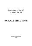
Manuale Tecnico - Technical Manual
QTEXT01
Rivelatore volumetrico a quadrupla
tecnologia per interni ed esterni
Quadruple technology volumetric
indoor and outdoor detector
090000844
Manuale Tecnico - QTEXT01 - 090000844 - Technical Manual
AVVERTENZE - FOREWORD
PER L’INSTALLATORE: Attenersi scrupolosamente alle normative vigenti sulla realizzazione di impianti elettrici e sistemi di sicurezza, oltre che alle prescrizioni del costruttore
riportate nella manualistica a corredo dei prodotti.
Fornire all’utilizzatore tutte le indicazioni sull’uso e sulle limitazioni del sistema installato, specificando che esistono norme specifiche e diversi livelli di prestazioni di sicurezza
che devono essere commisurati alle esigenze dell’utilizzatore.
Far prendere visione all’utilizzatore delle avvertenze riportate in questo documento.
PER L’UTILIZZATORE: Verificare periodicamente e scrupolosamente la funzionalità dell’impianto accertandosi della correttezza dell’esecuzione delle manovre di inserimento
e disinserimento. Curare la manutenzione periodica dell’impianto affidandola a personale specializzato in possesso dei requisiti prescritti dalle norme vigenti. Provvedere a
richiedere al proprio installatore la verifica dell’adeguatezza dell’impianto al mutare delle condizioni operative (es. variazioni delle aree da proteggere per estensione, cambiamento
delle metodiche di accesso ecc...)
Questo dispositivo è stato progettato, costruito e collaudato con la massima cura, adottando procedure di controllo in conformità alle normative vigenti. La piena rispondenza
delle caratteristiche funzionali è conseguita solo nel caso di un suo utilizzo esclusivamente limitato alla funzione per la quale è stato realizzato, e cioè:
QTEXT01 - Rivelatore volumetrico a quadrupla tecnologia per interni ed esterni
Qualunque utilizzo al di fuori di questo ambito non è previsto e quindi non è possibile garantire la sua corretta operatività.
I processi produttivi sono sorvegliati attentamente per prevenire difettosità e malfunzionamenti; purtuttavia la componentistica adottata è soggetta a guasti in percentuali
estremamente modeste, come d’altra parte avviene per ogni manufatto elettronico o meccanico. Vista la destinazione di questo articolo (protezione di beni e persone) invitiamo
l’utilizzatore a commisurare il livello di protezione offerto dal sistema all’effettiva situazione di rischio (valutando la possibilità che detto sistema si trovi ad operare in modalità
degradata a causa di situazioni di guasti od altro), ricordando che esistono norme precise per la progettazione e la realizzazione degli impianti destinati a questo tipo di applicazioni.
Richiamiamo l’attenzione dell’utilizzatore (conduttore dell’impianto) sulla necessità di provvedere regolarmente ad una manutenzione periodica del sistema almeno
secondo quanto previsto dalle norme in vigore oltre che ad effettuare, con frequenza adeguata alla condizione di rischio, verifiche sulla corretta funzionalità del sistema
stesso segnatamente alla centrale, sensori, avvisatori acustici, combinatore/i telefonico/i ed ogni altro dispositivo collegato. Al termine del periodico controllo l’utilizzatore
deve informare tempestivamente l’installatore sulla funzionalità riscontrata.
La progettazione, l’installazione e la manutenzione di sistemi incorporanti questo prodotto sono riservate a personale in possesso dei requisiti e delle conoscenze necessarie
ad operare in condizioni sicure ai fini della prevenzione infortunistica. E’ indispensabile che la loro installazione sia effettuata in ottemperanza alle norme vigenti. Le parti interne
di alcune apparecchiature sono collegate alla rete elettrica e quindi sussiste il rischio di folgorazione nel caso in cui si effettuino operazioni di manutenzione al loro interno prima
di aver disconnesso l’alimentazione primaria e di emergenza. Alcuni prodotti incorporano batterie ricaricabili o meno per l’alimentazione di emergenza. Errori nel loro collegamento
possono causare danni al prodotto, danni a cose e pericolo per l’incolumità dell’operatore (scoppio ed incendio).
FOR THE INSTALLER:
Please follow carefully the specifications relative to electric and security systems realization further to the manufacturer’s prescriptions indicated in the manual provided.
Provide the user the necessary indication for use and system’s limitations, specifying that there exist precise specifications and different safety performances levels that should
be proportioned to the user needs. Have the user view the directions indicated in this document.
FOR THE USER:
Periodically check carefully the system functionality making sure all enabling and disabling operations were made correctly.
Have skilled personnel make the periodic system’s maintenance. Contact the installer to verify correct system operation in case its conditions have changed (e.g.: variations
in the areas to protect due to extension, change of the access modes, etc…)
This device has been projected, assembled and tested with the maximum care, adopting control procedures in accordance with the laws in force. The full correspondence to
the functional characteristics is given exclusively when it is used for the purpose it was projected for, which is as follows:
QTEXT01 - Quadruple technology volumetric indoor and outdoor detector
Any use other than the one mentioned above has not been forecasted and therefore it is not possible to guarantee its correct operativeness.
The manufacturing process is carefully controlled in order to prevent defaults and bad functioning. Nevertheless, an extremely low percentage of the components used is
subjected to faults just as any other electronic or mechanic product. As this item is meant to protect both property and people, we invite the user to proportion the level of
protection that the system offers to the actual risk (also taking into account the possibility that the system was operated in a degraded manner because of faults and the like),
as well reminding that there are precise laws for the design and assemblage of the systems destinated to these kind of applications.
The system’s operator is hereby advised to see regularly to the periodic maintenance of the system, at least in accordance with the provisions of current legislation,
as well as to carry out checks on the correct running of said system on as regular a basis as the risk involved requires, with particular reference to the control unit,
sensors, sounders, dialler(s) and any other device connected. The user must let the installer know how well the system seems to be operating, based on the results
of periodic checks, without delay.
Design, installation and servicing of systems which include this product, should be made by skilled staff with the necessary knowledge to operate in safe conditions in order
to prevent accidents. These systems’ installation must be made in accordance with the laws in force. Some equipment’s inner parts are connected to electric main and therefore electrocution may occur if servicing was made before switching off the main and emergency power. Some products incorporate rechargeable or non rechargeable
batteries as emergency power supply. Their wrong connection may damage the product, properties and the operator’s safety (burst and fire).
Timbro della ditta installatrice - Your dealer/installer:
[email protected]
elmospa.com
2
Manuale Tecnico - QTEXT01 - 090000844 - Technical Manual
1. GENERALITA’
1. GENERALS
QTEXT01 il nuovo rilevatore volumetrico a quadrupla tecnologia
ideale per uso sia esterno sia interno in ambito industriale, commerciale e residenziale. Progettato per rispondere alla sempre maggior
richiesta di sensori dalle prestazioni elevate, il QTEXT01 unisce
un’accurata capacità di analisi del segnale ricevuto con complessi
algoritmi a quanto di più sofisticato e disponibile nel campo dei microprocessori.
Punto di forza di questo rilevatore è l’impiego di un doppio IR digitale
che unito alla doppia sezione MW garantiscono un’altissima precisione di rilevazione e un’elevata immunità ai disturbi.
I due sensori PIR sincronizzati garantiscono una copertura termica
tridimensionale della zona protetta; i segnali rilevati dai due sensori
PIR con ottiche FRESNEL separate e indipendenti, sono elaborati e
interpolati tra di loro in modo che siano considerate minacce solo le
rilevazioni con segnali simili in entrambi i canali. La rilevazione quindi è altamente immune ai falsi allarmi poiché anche gli sbalzi di temperatura, i riflessi e il passaggio di animali, non generando segnali
simili in entrambi i canali, sono ignorati. Completano le caratteristiche di protezione della sezione IR la funzione di antimascheramento a 4 canali IR attivi per il controllo delle ottiche del rilevatore i filtri
al Silicio anti luce bianca su entrambi i PIR e la dotazione standard
della lente grandangolare gestibile anche in modalità pet-immunity,
della lente a lunga portata e della lente per protezione a barriera verticale.
La sezione a MW, composta da un modulo con due canali a frequenze e impulsi Doppler differenti, gestibile sia in modalità “AND” sia
“OR”, è in grado di rilevare la distanza dei soggetti in movimento in
avvicinamento o allontanamento, escludendo tutti quei falsi allarmi
derivati dai soggetti che oscillano, ma non si spostano.
La protezione Tamper del contenitore e il sensore inerziale incorporato per la rilevazione degli urti e degli spostamenti del contenitore
sono un’ulteriore plus di questo rilevatore contro l’eventuale manomissione.
Le dimensioni ridotte e contenute, il design curato, lo snodo 3D per
il corretto posizionamento del rilevatore con il passaggio cavi integrato e il tettuccio integrato completano i punti di forza del QTEXT01.
QTEXT01 is the new quadruple technology volumetric detector ideal
for use both indoor and outdoor in industrial, commercial and residential installations. Designed to meet the increasing demand for
high-performance detectors, the QTEXT01 combines careful capabilities of analysis of the received signal with complex algorithms to
the more sophisticated and latest available microprocessors.
The key point of this detector is the use of a double Digital-IR which
is coupled to the double MW section ensuring an extremely high detection accuracy and high noise immunity.
The two synchronized PIR sensors guarantee a three-dimensional
thermal coverage of the protected area, the signals detected by the
two PIR sensors with separate and independent Fresnel lenses are
processed and interpolated between them so that they can consider
threats only the detections with similar signals in both channels. The
detection is highly immune to false alarms because even temperature changes, reflections, and animal crossing, not generating similar signals in both channels, are ignored.
The security features of the IR section are rounded out by the antimasking function with 4 active IR channels to control the detector’s
optics by the anti-white light Silicon filters on both the PIR and the
supplied wide-angle lens which can also be installed in pet-immunity mode, the long range lens and the vertical protection barrier
lens.
The MW section, consisting of a module with two channels with different frequencies and Doppler pulse, manageable in both “AND”
and “OR” operation mode, is able to detect the distance of an approaching or receding subject, excluding all those false alarms derived from subjects that swing, but do not move.
The anti-tamper of the container and the built-in inertial sensor for
the detection of shock and movements of the sensor are other plus
of this detector against any breaking in.
The small and contained dimensions, the refined design, the 3D
adjusting bracket the correct positioning of the detector with the full
cable management and the integrated sunshield round out the key
points of the QTEXT01.
2. CARATTERISTICHE TECNICHE
2. TECHNICAL SPECIFICATIONS
Model:
QTEXT01
Microwave section
MW module:
single with double frequency
Coverage area:
90° x 15mt
Frequency:
10.525 GHz
Emitted signal:
pulsed
Anti-swing:
<20° frequency from 0.5 to 3Hz
Infrared section
PIR sensor:
two digital sensors immune
to RF noise
RF/EMI immunity:
>30 V/m (30 MHz - 1 GHz)
Lens type:
Fresnel lens
Withe light protection:
> 15000 LUX with silicon filter
Modello:
QTEXT01
Sezione a microonde
Modulo MW:
singolo a doppia frequenza
Area di copertura:
90° x 15mt
Frequenza:
10.525 GHz
Segnale emesso:
impulsato
Anti-swing:
<20° frequenza da 0.5 a 3Hz
Sezione infrarosso
Sensori PIR:
due di tipo digitale immuni ai
disturbi RF
Immunità RF/EMI:
>30 V/m (30 MHz - 1 GHz)
Tipo di lente:
Lenti di Fresnel
Prot. dalla luce bianca:
> 15000 LUX con filtro al silicio
3
[email protected]
elmospa.com
Manuale Tecnico - QTEXT01 - 090000844 - Technical Manual
Area di copertura lente
standard RL300F:
90° x 15 mt
Area di copertura lente lunga
portata RL300LR:
5° x 23mt
Area di copertura lente
protezione barriera verticale
RL300B:
5° x 15m
Area di copertura con lente
grandangolare ed
installazione pet-immunity:
90° x 15m H:1.5m
Circuito
antimascheramento:
4 IR interni
24H Tamper:
protezione apertura del coperchio,
sensore inerziale contro vibrazioni,
spostamenti, urti
Temporizzazioni
Allarme:
2 - 3s
Stand-by all’accensione:
20s
Tempo di reazione
al Walk test:
15s
Tempo di accensione del
led rosso di allarme:
2 - 3s
Caratteristiche elettriche
Alimentazione:
12Vcc (9V : 16Vcc)
Assorbimento:
35 mA stand-by
60 mA in allarme
Uscita di allarme:
con relè allo stato solido
Tipo e portata dei contatti:
C - NC max.100mA/30Vcc
resistenza di contatto <30 Ohm
Uscita antimascheramento:
con relè allo stato solido
Tipo e portata dei contatti:
C - NC max.100mA/30Vcc
resistenza di contatto <30 Ohm
24H Tamper:
interruttore interno
Tipo e portata dei contatti:
C - NC max. 50mA/30Vcc
resistenza di contatto <30 Ohm
Caratteristiche meccaniche
Tipi di installazione:
a muro o ad angolo, inclinato solo
installando lo snodo in dotazione con
regolazione in alto di 90 gradi, in
basso di 30 gradi,
di 45 gradi sinistra /destra.
Altezza di installazione:
1.5mt : 2.4 mt
Dimensioni:
L110 x H220x P123 mm
Peso con tettuccio e snodo:
600 g
Condizioni operative:
-10°C : +50°C - 95% UR
Grado di protezione del
contenitore:
IP54
Dotazione:
staffa con viti di fissaggio, lenti
RL300B, RL300F e RL300LR , viti e
tasselli di fissaggio chiave a brugola,
manuale tecnico.
Wide angle standard lens
coverage area RL300F:
Long range lens coverage
area RL300LR:
Vertical protection
curtain lens coverage
area RL300B:
Wide angle coverage area
and pet-immunity
installation:
Antimask
circuit:
24H Tamper:
Alarm:
Power-On stand-by:
Reaction time to Walking
test:
90° x 15 mt
5° x 23mt
5° x 15m
90° x 15m H:1.5m
4 internal IR devices
cover opening protection, inertial
switch for vibrations, impact or
movements
Timings
2 - 3s
20s
15s
Red alarm indication:
2 - 3s
Electrical characteristics
Power supply:
12Vdc (9V : 16Vdc)
Power consumption:
35 mA stand-by
60 mA in allarm
Alarm output:
solid state relay
Contacts characteristics:
COM - NC max. 100mA/30Vdc
Ron resistance <30Ohm
Antimask alarm output:
solid state relay
Contacts characteristics:
COM - NC max. 100mA/30Vdc
Ron resistance <30 Ohm
24H tamper:
mechanical switch
Contacts characteristics:
COM - NC max. 50mA/30Vdc
Ron resistance <30 Ohm
Mechanical characteristics
Installation type:
wall or corner of the wall, with bracket
the sensor can be slanting adjust for up
-90 degree, down -30 degree, left/right
-45 degree.
Installation height:
1.5mt : 2.4 mt
Dimensions:
W110 x H220 x D120 mm
Weight:
600 g
Operation Temperature:
-10°C : +50°C - RH 95%
Housing protection:
IP54
Parts supplied:
bracket with screws,
RL300B, RL300F and RL300LR lens,
screws and dowels,
hexagonal key,
technical manual.
3. INSTALLAZIONE
3. INSTALLATION
QTEXT01 può essere fissato a parete, ad angolo, a 45 gradi su lato
destro o sinistro o inclinato utilizzando lo snodo fornito di serie.
QTEXT01 can be easily wall-mounted or corner-mounted, at 45 degree angle (left or right side) or with every inclination degree using
the supplied bracket.
[email protected]
elmospa.com
4
Manuale Tecnico - QTEXT01 - 090000844 - Technical Manual
ATTENZIONE! Non installare vicino a fonti di calore o condizionatori
di aria, evitare posizioni dove può ricevere luce solare diretta o riflessa, non installare su pareti poco stabili o su pareti metalliche, non
posizionare vicino a cavi elettrici di potenza e/o tensione di rete.
QTEXT01 va installato ad una altezza da 1,8m a 2,4m. L'altezza e
l'angolo di installazione influiscono sulla portata di rilevazione e
sull’immunità agli animali. Per garantire l’immunità agli animali, il rilevatore deve essere fissato tra 2.2m e 2.4m. La discriminazione
animali arriva fino a 20kg con il rilevatore installato a 2.2m senza inclinazione. L’immunità agli animali del rilevatore si riduce per altezze
di installazioni inferiori o inclinando il rilevatore verso il basso in
quanto l’area di rilevazione del sensore PIR superiore non è immune
agli animali. Per altezze di installazione basse, al di sotto di 1.7m (tipica 1.5m), ov e è richiesta la f unzione discriminazione animali,
occorre utilizzare la lente RL300F in dotazione.
ATTENTION! Do not install near to heat or cold sources, or subject
to direct or reflected sunlight, do not install on a unstable base, do
not install near electric power cables.
QTEXT01 should be mounted from 1,8 to 2,4 meters of height. The
height and angle of installation affects the detection range and the
pet immunity sensitivity. To ensure optimum pet immunity, the detector shouldbe installed from 2,2m to 2,4m.
The detector’s pet immunity is up to 20kg when the detector is
mounted at 2,2m without inclination. The pet immunity decreases
when tilting the detector down or when installing the detector below
2,2m because the detection area of the upper PIR sensor is not pet
immune.
For low installations, below 1,7m (typical 1,5m) in which pet immunity is required, use the supplied RL300F lens.
C
B
A
To open the detector, unscrew the screw A; then unscrew the screw
B and remove the front cover; unscrew the holding screw C, move
the PC board downward and gently lifting up the PC board (do not
touch the PIR sensors by hand). The circular and rectangular indentations at the bottom base are the knockout holes for proper installation and wire entry. Break the desired knockout holes for
proper installation (flat mounting, corner mounting or 45 degree angle mounting). Insert the wire through the wire access hole and
mount the external base to the wall. Insert the wire in the opening
on the rear of the detector base and secure the detector base to the
external base. Slide the wires through the slits of the internal base,
reinstall the PC board, connect wires to terminal block and proceed
to configure the detector. If you want to secure the detector base
and the external base more firmly, you can insert the screw supplied
on the hole present on the higher part of the external base and then
close the detector. When finished, close the front cover.
Smontare il rilevatore dalla base esterna rimuovendo la vite A; rimuovere poi la vite B e aprire il coperchio frontale; quindi togliere la vite
C ed estrarre la scheda spostandola verso il basso fino a liberarla dai
ganci (attenzione a non toccare i sensori PIR). Nel fondo della base
esterna è presente un foro rettangolare premarcato per il passaggio
dei cavi e vari fori premarcati da aprire a seconda dell'installazione
scelta. Questi permettono il fissaggio in piano, con inclinazione di
45°, oppure ad angolo. Aprire i fori necessari, passare il cavo e fissare la base esterna al muro. Passare il cavo nell'apertura presente
nella base interna del rilev atore e fissare la base interna a quella
esterna. Guidare il cavo attraverso le feritoie della base interna fino
alla morsettiera. Installare la scheda e procedere con le impostazioni
ed i collegamenti. Se si desidera fissare il rilevatore più saldamente
alla base esterna, inserire la vite a corredo nel foro presente nella
parte alta della base interna, quindi chiudere il rivelatore.
Una volta finito, chiudere il coperchio frontale.
5
[email protected]
elmospa.com
Manuale Tecnico - QTEXT01 - 090000844 - Technical Manual
3.1 FORI PREMARCATI
5
3.1 KNOCKOUT HOLES
1
3
2
3
2
4
3
2
4
3
2
1= Foro per passaggio cavi / Wire access hole.
2 = Fori per installazione a parete / Flat wall mounting holes.
3 = Fori per installazione angolare (45°) / Corner mounting holes
(for 45° mounting use 2 holes only).
4 = Fori perf issare lo snodo / Bracket mounting holes.
5 = Foro per la vite di bloccaggio della base / Hole for the optional holding screw.
3.2 INSTALLAZIONE DELLO SNODO
3.2 BRACKET INSTALLATION
Smontare il rilevatore dalla base esterna, aprire il coperchio frontale
ed estrarre la scheda elettronica. Aprire sulla base del rilevatore il
foro per il passaggio dei cavi e i due fori per fissare lo snodo.
Far passare il cav o esterno attraverso le predisposizioni dello snodo
ed estrarlo facendolo passare attraverso il passaggio cavi interno
dello snodo. Inserire i cavi esterni che arrivano dallo snodo facendoli
passare tramite la predisposizione della base esterna. Fissare lo snodo alla parete con 4 viti e fissare la base esterna allo snodo con 2
viti. Regolare l’orientamento dello snodo fino ad ottenere la posizione
desiderata e poi stringere le viti di blocco orientamento snodo.
Inserire la base interna nella base esterna, inserire i cavi attraverso
la base interna e fissare la base interna a quella esterna. Effettuare
i collegamenti, reinserire la scheda nell’alloggiamento e chiudere il
rilevatore.
Release the external base, open the front cover and remove the PC
board. Open knockout holes on external base for wire access and
locking screws. Insert external cable wiring through knockout holes
of the bracket and extract them through the wire access of the bracket. Insert external cable wiring from the bracket through knockout
wire access hole on the external base. Secure the bracket to the wall
by using 4 screws. Secure the external base to the bracket by using
2 screws. Tilt and rotate the bracket to the desired position. Then secure the angle locking screws. Insert all wiring cables through the
internal base and secure it to the external base.
Make connections, reinstall the PC board and close the detector.
4
2
A
4
B
3
4
4
A
2
1, 2 = Predisposizioni per passaggio cavo esterno /
External cable access holes.
3 = Passaggio cavi interno / Wire access hole
4 = Fori per montaggio a parete / Flat wall mounting holes.
[email protected]
elmospa.com
C
A = Viti a brugola per blocco orientamento orizzontale /
Angle locking screws.
B = Viti per blocco orientamento verticale /
Wire access hole Angle locking screws.
C = Fori per fissare lo snodo / Bracket mounting holes.
6
Manuale Tecnico - QTEXT01 - 090000844 - Technical Manual
4. IMPOSTAZIONI
4. SETTINGS
Indicatori a led / Led indicators
Vite fissaggio scheda / PCB holding screw
Regolazione della microonda / MW range
NON TOCCARE / DO NOT TOUCH
SW
FUNZIONE/FUNCTION
ON
OFF
SW1
Led luminosi/light indicators
Abilitati / enabled
Disabilitati / disabled
SW2
Sensibilità PIR/PIR sensitivity
Vedi tabella / see table
SW3
Sensibilità PIR/PIR sensitivity
Vedi tabella / see table
SW4
Modalità di allarme/alarm mode
OR
AND
SW5
Tipo di lente/lens type installed
Tenda /LR curtain /LR
Grandangolare /wide angle
SW6
Led Rosso/3 LED
Solo led Rosso/Red led only
3 led
SW7
Antimask
Abilitato / enabled
Disabilitato / disabled
SW8
Sensore inerziale / inerthial sensor
Abilitato / enabled
Disabilitato / disabled
LED DI VISUALIZZAZIONE
SW1
LIGHT INDICATORS LED
FUNZIONE/FUNCTION
ON
OFF
ON
I led indicheranno le condizioni di allarme e guasto
/
The Leds indicate alarm conditions and fault.
Disabilitati /disabled
7
[email protected]
elmospa.com
Manuale Tecnico - QTEXT01 - 090000844 - Technical Manual
Le indicazioni che i led forniscono nelle varie condizioni di funzionamento sono le seguenti:
LED
The leds indications in the different conditions are:
CONDIZIONE/CONDITION
DESCRIZIONE/DESCRIPTION
ON
Rilevazione PIR / PIR detection
Lampeggiante/ Flashing
Antimascheramento / Antimask
Verde / Green
ON
Rilevazione MW / MW detection
Rosso / Red
ON
Allarme / Alarm
Lampeggiante/ Flashing
Riservato per altro uso / Reserved
Lampeggio sequenziale / sequential flashing
Inizializzazione durante il Power ON / Initializing during power on
Giallo / Yellow
Tutti / All
Sensibilità di rilevazione
Detection sensitivity
Utilizzare i dip SW2 e SW3 per regolare la sensibilità
Use the dipswitches SW2 and SW3 to adjust the sensitivity.
SENSIBILITÀ DI RILEVAZIONE / DETECTION SENSITIVITY
SW2
SW3
DESCRIZIONE/DESCRIPTION
Bassa / low
OFF
OFF
Generazione dell’allarme dopo 8 impulsi /
Alarm activated after 8 pulses detected from PIR sensors.
Media / medium
OFF
ON
Generazione dell’allarme dopo 6 impulsi /
Alarm activated after 6 pulses detected from PIR sensors.
Normale / standard
ON
OFF
Generazione dell’allarme dopo 4 impulsi /
Alarm activated after 4 pulses detected from PIR sensors.
Massima / max.
(Default)
ON
ON
Generazione dell’allarme dopo 2 impulsi /
Alarm activated after 2 pulses detected from PIR sensors.
Nota: i livelli sono impostati per le varie caratteristiche climatiche,
porre attenzione nell’impostazione del dip, al termine del setup controllare che il rivelatore abbia la funzionalità richiesta. E’ consigliata
la posizione di Default.
Note: these levels are set for the various climatic conditions, be careful to set the dip, at the end of the setup test the detector for the
operativity required. Recommended position = Default.
AND - OR
AND - OR
FUNZIONE/FUNCTION
SW4
DESCRIZIONE/DESCRIPTION
AND
OFF
Segnalazione di allarme quando entrambe le tecnologie rilevano movimento. /
Alarm signal when both sensor’s signals (PIR AND MW) are present at the same time.
OR
ON
Segnalazione di allarme quando anche una sola tecnologia rileva un movimento. /
Alarm signal when one of the sensor’s signals (PIR OR MW) is present.
Tipi di lente
Lens models
QTEXT01 viene fornito con la lente standard (RL300) già montata.
Altre tre lenti, con diversi diagrammi di copertura, sono fornite in
dotazione:
- lente PET-ALLEY per installazioni da 1m a 1.7m di altezza (RL300F).
- lente lunga portata (RL300LR).
- lente tenda (RL300B).
Nota: impostare il dip SW5 in base al tipo di lente utilizzato (i codici
prodotto sono marcati sulle lenti). Soltanto con le lenti RL300 e
RL300F il sensore è PET immune.
QTEXT01 comes equipped with the standard lens (RL300).
Other three lenses, with different detection patterns, are supplied
with the detector:
- pet lens for low up to 1.7m of height (RL300F).
- long range lens (RL300LR).
- curtain lens (RL300B).
[email protected]
elmospa.com
Note: the detector’s optics can be set with the switch SW5 (part
numbers are printed on the lenses). RL300B and RL300LR are not
PET immune.
8
Manuale Tecnico - QTEXT01 - 090000844 - Technical Manual
Abilitazione led rosso
Red led enable
FUNZIONE/
FUNCTION
SW6
DESCRIZIONE/DESCRIPTION
3 LED
OFF
I led indicheranno le condizioni di Allare e Guasto / The Leds indicate alarm condition and fault.
Solo led Rosso /
Red LED only
ON
Solo il LED rosso è attivo. L’opzione è consigliata per mascherare l’operatività del rilevatore.
Only the red LED will operate. This option is recommended to mask the operativity.
Antimasking
La funzione antimascheramento (AM) attiverà l'uscita di antimasche
ramento nel caso sia rilevata la presenza di un oggetto troppo vicino
al rivelatore. L'effettiva distanza di rivelazione è di 5cm circa.
La funzione può essere abilitata/disabilitata con il selettore SW7. Se
viene posizionato un oggetto vicino al sensore nel raggio di azione
dell'AM, oppure se il sensore dovesse essere mascherato con spray,
vernici o lacche, allora l’uscita AM si attiverà solo se il mascheramento è presente per almeno 15 secondi.
La condizione di mascheramento è indicata dal lampeggio del LED
giallo. L’uscita antimask è attiva per tutto il tempo in cui è presente
il mascheramento, una volta rimosso l’uscita si disattiva automaticamente.
ANTIMASKING
The antimask function (AM) activates the antimask output if it's detecting an object too close to the detector (~5cm). The function can
be enabled or disabled setting SW7. If an attempt is made to mask
the lens with a sticker or to put a masking object close to the lens,
the antimask output will be activated 15 seconds after masking.
Only if the object remains near to the detector for more than 15 seconds, the antimask output will be activated. This activation is
shown by a yellow LED flash. When the object is away, a few seconds after the antimask output will be restored to its normal condition.
AM
SW7
DESCRIZIONE/DESCRIPTION
Disabilitato - disabled
OFF
Controllo antimascheramento disabilitato - Antimask function disabled
Abilitato - enabled
ON
Controllo antimascheramento abilitato - Antimask function enabled
Sensore inerziale
Se abilitato, allora l'uscita di antimascheramento verrà attivata nel
caso sia rilevato lo spostamento del rivelatore o una vibrazione
dell’unità. La rilevazione di vibrazioni può essere attivata impostando
il selettore SW8.
Shock sensor
If enabled, the antimask output will activate if the detector is moved
or after a vibration.
The vibration detection can be enabled setting SW 8.
Sensore inerziale / Shock sensor
SW8
DESCRIZIONE/DESCRIPTION
Disabilitato - disabled
OFF
Controllo vibrazioni disattivo - Vibration detection disabled
Abilitato - enabled
ON
Controllo vibrazioni attivo - Vibration detection enabled
5. PREDISPOSIZIONI
5. OPTIONAL INSTALLATION
Il fondo del contenitore è predisposto per ospitare anche delle schede elettroniche studiate per aumentare le prestazioni del rivelatore
come ad esempio il modulo concentratore RIVERMINI2. Come si rileva dal manuale del concentratore, esso dovrà essere cablato con
il rivelatore e indirizzato correttamente per poi essere isolato e posizionato sotto la scheda del QTEXT01.
On the base of the detector housing it is possible to install electronic
boards designed to increase the detector performance level (e.g.
RIVERMINI2 concentrator module.)
As it can be read in the concentrator manual, it must be wired to the
detector and addressed correctly in order to be insulated and positioned under the QTEXT01 board afterwards.
L’abbinamento è compatibile con ETR, NET, VILLEGGIO e TITANIA.
Compatible with ETR, NET, VILLEGGIO and TITANIA control units.
9
[email protected]
elmospa.com
Manuale Tecnico - QTEXT01 - 090000844 - Technical Manual
RS485
RIVERMINI2
Esempio installativo / Example of installation
6. COLLEGAMENTI
Alimentazione 12Vcc
12Vdc power supply
6. WIRINGS
Contatti C-NC del
contatto di Tamper
C - NC Tamper output
Contatti C-NC del circuito antimascheramento/ vibrazione.
Nota: programmare l’ingresso in centrale
come "Tecnologico".
C - NC antimask/vibration output.
Note: for a correct use set the input of control
unit to "Technological event"
Contatti C-NC del relè di allarme
C - NC alarm output relay
Morsetto libero, per connessione di una
eventuale resistenza di fine linea.
Free terminal that can be used to connect
EOL resistor
-
Ingresso per test da remoto collegandolo al :
TEST OK = il relè di allarme si attiva per qualche secondo.
KO - GUASTO = l’uscita AM è attiva.
Used for remote alarm testing when connect to :
TEST OK= alarm relay is temporary opened.
KO - FAILURE = AM relay is opened.
-
[email protected]
elmospa.com
10
Esclusione dei led se è al negativo di alimentazione e SW1= ON
LEDs are disabled if the terminal is connect to " " and SW1= ON
-
Future applicazioni
Future applications
Esclusione del circuito antimask e
spegnimento dei led quando è al
negativo di alimentazione. Abilitati
se è al +12V o libero e se
SW7 =ON e SW1= ON
Antimask and LEDs are disabled if
the terminal is connect to " ". Enabled if connect to +12Vdc or no
connection and if SW7 =ON and
SW1= ON
-
Manuale Tecnico - QTEXT01 - 090000844 - Technical Manual
Cablaggio del concentratore RIVERMICRO2
RIVERMICRO2 wirings
Linea seriale RS485 della centrale compatibile.
RS485 of compatible control unit.
Nota: programmare l’ingresso in centrale come "Tecnologico".
Note: for a correct use set the input of control unit to "Technological event".
RIVERMICRO2
QTEXT01
7. DIAGRAMMI DI COPERTURA
7. COVERAGE DIAGRAMS
Lente grandangolare (RL300F) fornita installata.
Wide angle lens (RL300F) supplied installed.
Vista dall’alto / Top view
8
6
Vista laterale / Side view
4
2
MICROWAVE
0
MICROONDA
2
2
0
4
15 mt
6
8
mt
11
[email protected]
elmospa.com
Manuale Tecnico - QTEXT01 - 090000844 - Technical Manual
Lente a lunga portata (RL300LR) fornita nella confezione
Long range lens (RL300LR) supplied with the product.
Vista laterale / Side view
Vista dall’alto / Top view
2.2
Long range lens (RL300LR) supplied with the product.
0
5°
23 mt
Vertical curtain lens (RL300B) supplied with the product.
Lente a tenda verticale (RL300B) fornita nella confezione
Vista dall’alto / Top view
Vista laterale / Side view
Nota: la portata e la sensibilità del sensore dipendono dalla temperatura e dalle caratteristiche dell'ambiente nel quale QTEXT01 è installato.
Note: the maximum detection length and detector sensitivity may
vary depending on temperature and environmental conditions.
8. WALK TEST
8. WALK TEST
Dopo 2 minuti dall’alimentazione del sensore, effettuare una prova di
movimento all’interno dell’area protetta e verificare il buon funzionamento e la copertura del rivelatore. La scheda del rivelatore può essere spostata per regolare la copertura IR. Per ridurre l’area di
copertura spostare in alto la scheda elettronica del rilevatore o, se
utilizzato, muovere lo snodo verso il basso. La portata della microonda può invece essere
regolata da 6 a 20m mediante il
potenziometro situato sulla
scheda elettronica. Ruotare il
potenziometro in senso orario
per aumentare la portata e in
senso antiorario per diminuirla.
E’ possibile utilizzare il buzzer in
dotazione quando la luce solare
non permette di visualizzare lo
stato dei LED. Il suono continuo
del buzzer si interromperà ad
ogni rilevazione (condizione di
allarme).
Two minutes after applying power, start walking across the detection zone to verify proper operation. The PC board position can be
adjusted to obtain different IR covering distance. To reduce the detection range, slide up or tilt down the swivel bracket.
The MW range can be adjusted by using the potentiometer on the
PCB from 6 to 20m.
Rotate
the
potentiometer
clockwise to increase MW range,
counterclockwise to decrease
range.
The buzzer supplied with product
can be used when it is hard to see
the LED. The buzzer will stop
sounding whenever motion is detected (alarm state).
[email protected]
elmospa.com
12
Manuale Tecnico - QTEXT01 - 090000844 - Technical Manual
9. SOSTITUZIONE DELLE LENTI
9. REPLACING LENSES
Nella parte interna del coperchio frontale svitare le 6 viti del supporto
lenti. Per sganciare il supporto lenti effettuare una leggera pressione
sulle lenti dalla parte anteriore del coperchio. Sganciare la lente dal
supporto facendo leggermente leva sulle clip laterali della lente.
Inserire le 4 clip della lente da sostituire negli appositi fori del supporto. Inserire il supporto lenti nel coperchio f rontale e fissarlo avvitando le 6 viti.
Unlock the six screws that hold the lens holding sleeve from the
back of the front cover. To release the protective sleeve, gently push
the lens from the external side of the front cover.
Remove the lens from the sleeve by gently pushing the lens clips
that secure it to the sleeve. Replace the lens by placing the 4 clips
into the matching holes on the sleeve. Install the protective sleeve
back into place on the front cover and secure the 6 holding screws.
Lens rough surface
Superficie ruvida della lente.
13
[email protected]
elmospa.com
Manuale Tecnico - QTEXT01 - 090000844 - Technical Manual
10. AVVERTENZE PER LO SMALTIMENTO
10. DISPOSAL INSTRUCTIONS
Il prodotto QTEXT01 deve essere smaltito in accordo con le vigenti
disposizioni comunali e conferito in una discarica autorizzata per lo
smaltimento di prodotti elettronici; in caso di necessità è necessario
chiedere informazioni al proprio ufficio comunale per la N.U.
Il materiale utilizzato è altamente nocivo ed inquinante se disperso
nell’ambiente.
Dispose of QTEXT01 in compliance with current city regulations and
by leaving the device in a dumping ground authorized for the disposal of electronic products.
If required, please contact the appropriate city office for additional
information.
The materials used for this product are very harmful and polluting.
Do not disperse them in the environment.
[email protected]
elmospa.com
14
Manuale Tecnico - QTEXT01 - 090000844 - Technical Manual
11. POSIZIONAMENTI CONSIGLIATI
11. RECOMMENDED POSITIONS
Posizioni installative corrette.
Correct positions.
Posizioni installative sbagliate.
Wrong positions.
15
[email protected]
elmospa.com
12. INDICE
12. CONTENTS
1. GENERALITA’ . . . . . . . . . . . . . . . . . . . . . . . . . . . . . . . . . . . . . . . . . .3
2. CARATTERISTICHE TECNICHE . . . . . . . . . . . . . . . . . . . . . . . . . . . . .3
3. INSTALLAZIONE . . . . . . . . . . . . . . . . . . . . . . . . . . . . . . . . . . . . . . . .4
3.1.FORI PREMARCATI . . . . . . . . . . . . . . . . . . . . . . . . . . . . . . .6
3.2.INSTALLAZIONE DELLO SNODO . . . . . . . . . . . . . . . . . . . . . .6
4. IMPOSTAZIONI . . . . . . . . . . . . . . . . . . . . . . . . . . . . . . . . . . . . . . . .7
5. PREDISPOSIZIONI . . . . . . . . . . . . . . . . . . . . . . . . . . . . . . . . . . . . . .9
6. COLLEGAMENTI . . . . . . . . . . . . . . . . . . . . . . . . . . . . . . . . . . . . . . .10
7. DIAGRAMMI DI COPERTURA . . . . . . . . . . . . . . . . . . . . . . . . . . . . .11
8. WALK TEST . . . . . . . . . . . . . . . . . . . . . . . . . . . . . . . . . . . . . . . . . .12
9. SOSTITUZIONE DELLE LENTI . . . . . . . . . . . . . . . . . . . . . . . . . . . . .13
10. AVVERTENZE PER LO SMALTIMENTO . . . . . . . . . . . . . . . . . . . . .14
11. POSIZIONAMENTI CONSIGLIATI . . . . . . . . . . . . . . . . . . . . . . . . . .15
12. INDICE . . . . . . . . . . . . . . . . . . . . . . . . . . . . . . . . . . . . . . . . . . . . .16
1. GENERALS . . . . . . . . . . . . . . . . . . . . . . . . . . . . . . . . . . . . . . . . . . . 3
2. TECHNICAL SPECIFICATIONS . . . . . . . . . . . . . . . . . . . . . . . . . . . . 3
3. INSTALLATION . . . . . . . . . . . . . . . . . . . . . . . . . . . . . . . . . . . . . . . . 4
3.1.KNOCKOUT HOLES . . . . . . . . . . . . . . . . . . . . . . . . . . . . . . . 6
3.2.BRACKET INSTALLATION . . . . . . . . . . . . . . . . . . . . . . . . . . 6
4. SETTINGS . . . . . . . . . . . . . . . . . . . . . . . . . . . . . . . . . . . . . . . . . . . . 7
5. OPTIONAL INSTALLATION . . . . . . . . . . . . . . . . . . . . . . . . . . . . . . . 9
6. WIRINGS . . . . . . . . . . . . . . . . . . . . . . . . . . . . . . . . . . . . . . . . . . . 10
7. COVERAGE DIAGRAMS . . . . . . . . . . . . . . . . . . . . . . . . . . . . . . . . . 11
8. WALK TEST . . . . . . . . . . . . . . . . . . . . . . . . . . . . . . . . . . . . . . . . . . 12
9. REPLACING LENSES . . . . . . . . . . . . . . . . . . . . . . . . . . . . . . . . . . . 13
10. DISPOSAL INSTRUCTIONS . . . . . . . . . . . . . . . . . . . . . . . . . . . . . 14
11. RECOMMENDED POSITIONS . . . . . . . . . . . . . . . . . . . . . . . . . . . 15
12. CONTENTS . . . . . . . . . . . . . . . . . . . . . . . . . . . . . . . . . . . . . . . . . 16
Edizione Gennaio 2013 - January 2013 edition - Made in China
090000844
Le informazioni e le caratteristiche di prodotto non sono impegnative e potranno essere modificate senza preavviso.
Product specifications as described above do not bind the manufacturer and may be altered without prior notice.
EL.MO. SpA Via Pontarola, 70 - 35011 Campodarsego (PD) - Italy
Tel. +390499203333 (R.A.) - Fax +390499200306 - Help desk +390499200426 - www.elmospa.com - [email protected].