Download DOX 35 Italiano English
Transcript
DOX35
Water Doser
USER’S INSTRUCTION MANUAL
CODE 2600101 – Rev. 05 - 20.02.2012
Manual Code 2600101
Error
L/°C
pnd/°F
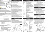
Fig. 1 (Descrizione esterna della macchina; Machine overview)
DOX 35 – Rev.05 - 20.02.2012
3/29
MAIN P.C. BOARD
BLACK
RED
VIOLET
WHITE
BLACK
ORANGE
Manual Code 2600101
Y/G
Y/G
Y/G
LITER
COUNTER
Y/G
BLU (BLACK for UL vers.)
BROWN (RED for UL vers.)
Y/G
MAIN E.V.
INT. PROBE
POWER P.C. BOARD
BUZZER
PUMP
SUPPLY
Fig. 2 (Schema Elettrico; Wiring Diagram)
DOX 35 – Rev.05 - 20.02.2012
4/29
Manual Code 2600101
Fig. 3 (Dimensioni; Dimensions)
DOX 35 – Rev.05 - 20.02.2012
5/29
Manual Code 2600101
INDICE / INDEX
1- CARATTERISTICHE TECNICHE .................................................................... 8
1.1.
DESCRIZIONE ........................................................................................................8
2- INTERPRETAZIONE DEL MANUALE ............................................................. 9
3- ISPEZIONE PREVENTIVA ............................................................................. 9
4- REGOLE FONDAMENTALI DI SICUREZZA ................................................... 9
5- DICHIARAZIONE DEL COSTRUTTORE ....................................................... 10
5.1.
5.2.
5.3.
GARANZIA ..........................................................................................................10
DISIMBALLAGGIO ..............................................................................................10
MAGAZZINAGGIO .............................................................................................10
6- INSTALLAZIONE........................................................................................ 11
7- FUNZIONAMENTO.................................................................................... 13
7.1.
FUNZIONE SPECIALE SCARICO LIBERO ............................................................................13
8- ERRORI ..................................................................................................... 14
8.1.
8.2.
8.3.
8.4.
MANCANZA IMPULSI DAL CONTALITRI ............................................................................14
SONDA GUASTA .......................................................................................................14
CADUTA DI TENSIONE.................................................................................................14
TRAFILAMENTO ELETTROVALVOLE ..................................................................................15
9- MANUTENZIONE MACCHINA ................................................................. 15
10- SMALTIMENTO DELL’APPARECCHIATURA GIUNTA A FINE VITA............. 16
11- CERTIFICAZIONI....................................................................................... 16
12- INDIVIDUAZIONE DEI PROBLEMI E LORO RISOLUZIONE ......................... 17
13- PEZZI DI RICAMBIO.................................................................................. 28
1- TECHNICAL FEATURES.............................................................................. 18
1.1.
DESCRIPTION ......................................................................................................18
2- MANUAL INTERPRETATION ...................................................................... 19
3- PRELIMINARY INSPECTION ...................................................................... 19
4- BASIC RULES OF SAFETY .......................................................................... 19
5- MANUFACTURER DECLARATION............................................................. 20
5.1.
5.2.
5.3.
WARRANTY .........................................................................................................20
UNPACKING .......................................................................................................20
STORAGE ............................................................................................................20
6- INSTALLATION.......................................................................................... 21
DOX 35 – Rev.05 - 20.02.2012
6/29
Manual Code 2600101
7- UNIT OPERATION ..................................................................................... 23
7.1.
FREE BATCH SPECIAL FUNCTION ....................................................................................23
8- ERRORS .................................................................................................... 24
8.1.
8.2.
8.3.
8.4.
LITRES-COUNTER ERROR ..............................................................................................24
PROBE ERROR ..........................................................................................................24
POWER FAIL ............................................................................................................24
SOLENOID VALVE LEAKING ..........................................................................................25
9- MAINTENANCE INSTRUCTIONS ............................................................... 25
10- USELESS DEVICE DISPOSAL...................................................................... 26
11- CERTIFICATIONS ...................................................................................... 26
12- TROUBLESHOOTING................................................................................. 27
13- SPARE PARTS............................................................................................ 28
DOX 35 – Rev.05 - 20.02.2012
7/29
Manual Code 2600101
1- CARATTERISTICHE TECNICHE
Tensione (vedi targhetta sull’ apparecchio)
Frequenza
Potenza assorbita
Raccordi acqua in entrata
Scarico acqua
Temperatura massima dell’acqua in ingresso
Pressione massima dell’acqua in ingresso
Pressione minima dell’acqua in ingresso
Dosaggio massimo
Precisione sul dosaggio
Portata a 1 bar e 20°C
Portata a 5 bar e 20°C
Sonda interna
Fusibile per l’alimentazione
Fusibile per il telecomando pompa
230 Volt AC opp 115 Volt AC ± 10%
50/60 Hz
25 VA
½”
16 mm
65°C (149°F)
5 bar (72,5 psi)
1 bar (14,5 psi)
999,9 L; 99 lb + 15 oz; 999,9 lb
± 1%
25 L/min (55 lb/min)
55 L/min (121 lb/min)
Termoresistenza PT1000 ClasseA
250 V – T250 mA ritardato @ 230 V
250 V – T630 mA ritardato @ 115 V
250 V - F6,3 A
1.1. DESCRIZIONE
(Vedi Fig. 1)
1.
2.
3.
4.
5.
6.
7.
8.
9.
10.
11.
12.
Saracinesca rapida a sfera con tenuta OR.
Bocchettone con tenuta OR, per facilitare l’installazione.
Filtro per le impurità, con doppia rete inox.
Tasto [STOP/C] per l’arresto manuale o l’eventuale cancellazione della memoria.
Tasti ▲ e ▼ per l’impostazione della quantità.
Spina di alimentazione con fusibile e ricambio.
Spina per il controllo di una pompa, con fusibile e ricambio.
Tubo di dosaggio.
Tasto [START] per l’inizio o la ripresa del dosaggio.
Serie di spie di segnalazione.
Display digitale per la temperatura alla sonda interna, al decimo di grado.
Display digitale per la quantità d’acqua impostata, ancora da scaricare (durante il
dosaggio), o già scaricata (dopo aver premuto [STOP/C]).
DOX 35 – Rev.05 - 20.02.2012
8/29
Manual Code 2600101
2- INTERPRETAZIONE DEL MANUALE
Tutte le parti del testo di questo manuale maggiormente importanti per la sicurezza delle
persone e delle cose sono scritte in grassetto. Questo manuale mette a conoscenza
l’utente, l’installatore e il tecnico di manutenzione di tutte le informazioni tecniche
richieste per l’installazione, l’utilizzo e le operazioni di manutenzione ordinaria volte ad
assicurare una lunga durata della macchina. Se sono necessari dei pezzi di ricambio,
questi devono essere componenti originali. Le richieste di PEZZI di RICAMBIO e di
INFORMAZIONI riguardanti l’unità devono essere inviate al distributore o al centro di
assistenza più vicino, includendo il MODELLO e IL NUMERO DI PRODUZIONE della
MACCHINA riportati sull’etichetta delle caratteristiche tecniche.
Questo simbolo, utilizzato sulla macchina e nel presente manuale, indica:
Attenzione, rischio di scosse elettriche.
Questo simbolo, utilizzato sulla macchina e nel presente manuale, indica:
Attenzione, fare riferimento alla documentazione allegata.
Questo simbolo, utilizzato nel presente manuale, indica: Operazione non permessa.
3- ISPEZIONE PREVENTIVA
Ispezionare l’unità immediatamente dopo averla ricevuta; controllare attentamente tutti i
componenti in accordo con la bolla o fattura; segnalare eventuali danni dovuti al
trasporto e presentare immediatamente un reclamo al corriere.
NOTA IMPORTANTE: Il costruttore non è responsabile di alcun danno arrecato alle unità
durante il trasporto.
4- REGOLE FONDAMENTALI DI SICUREZZA
E’ vietato l’uso dell’apparecchio ai bambini e alle persone inabili non assistite
E’ vietato toccare l’apparecchio se si è a piedi nudi e con parti del corpo
bagnate o umide
E’ vietata qualsiasi operazione di pulizia prima di aver scollegato l’apparecchio
dalla rete elettrica.
E’ vietato modificare i dispositivi di sicurezza o di regolazione senza l’autorizzazione
e le indicazioni del costruttore.
E’ vietato staccare, torcere i cavi elettrici fuoriuscenti dall’apparecchio anche se
questo è scollegato dalla rete elettrica.
E’ vietato aprire l’apparecchio senza averlo preventivamente staccato dalla rete
elettrica.
E’ vietato disperdere e lasciare alla portata dei bambini il materiale dell’imballo in
quanto può essere potenzialmente pericoloso.
DOX 35 – Rev.05 - 20.02.2012
9/29
Manual Code 2600101
5- DICHIARAZIONE DEL COSTRUTTORE
IL COSTRUTTORE DECLINA OGNI RESPONSABILITA’ PER OGNI EVENTUALE DANNO
DERIVANTE DA UN USO IMPROPRIO DELLA MACCHINA E/O IN CONDIZIONI
AMBIENTALI FUORI DAL CAMPO AMMESSO.
5.1. GARANZIA
Il costruttore, tramite i suoi distributori autorizzati, garantisce all'utente finale, secondo
quanto riportato nelle condizioni qui di seguito, di riparare o sostituire gratuitamente
qualsiasi parte del presente prodotto che si guasti entro un anno dalla consegna del
prodotto. Tale guasto deve essersi verificato a seguito di un difetto del materiale o di
lavorazione e non essere il risultato dell'utilizzo in difformità alle istruzioni riportate nel
presente manuale.
I prodotti devono essere restituiti, salvo previo accordo di ritiro tramite corriere, al
costruttore, o a un suo distributore autorizzato, a spese del mittente.
Tutte le riparazioni o modifiche devono essere effettuate esclusivamente dal costruttore, o
dai suoi distributori autorizzati o in seguito all'espresso consenso del costruttore o dei suoi
distributori autorizzati.
Sono esclusi dalla garanzia i prodotti che sono stati usati in modo improprio, soggetti a uso
errato o a danno volontario o accidentale o a sovratensione.
Il costruttore non sarà responsabile di nessuna garanzia espressa a nome e per conto di se
stesso, da qualunque persona compresi suoi distributori, che non rientri nei termini
specificati nella presente garanzia, a meno che tale garanzia non venga da lui
espressamente approvata per iscritto.
5.2. DISIMBALLAGGIO
Disimballare con cura tutte le parti, e controllare che tutti i componenti siano presenti e in
buone condizioni.
Conservare l’imballo per eventuali spedizioni in caso di guasto.
A fine vita dell’apparecchio eliminare i materiali d'imballaggio in un modo sicuro e in
conformità alle norme locali. Prestare particolare attenzione ai gusci antiurto in polistirolo
espanso. Lo scatolone esterno è di cartone ondulato e può essere riciclato.
5.3. MAGAZZINAGGIO
Questo prodotto ha una durata a magazzino prolungata. Tuttavia occorre prestare
attenzione dopo il magazzinaggio, ed assicurarsi che tutte le parti funzionino
correttamente.
DOX 35 – Rev.05 - 20.02.2012
10/29
Manual Code 2600101
6- INSTALLAZIONE
Le operazioni fondamentali relative a sollevamento, trasporto, installazione,
avviamento, manutenzione e riparazione devono essere effettuate esclusivamente
da personale qualificato. L'unità deve essere isolata dall'alimentazione elettrica
mentre si effettua l'intervento.
Sul coperchio, accanto alle prese di alimentazione, sono presenti dei fusibili che
possono essere sostituiti dall’utente.
Il lavoro di installazione deve essere svolto da personale competente sotto la supervisione
di una persona qualificata. Tutti i collegamenti elettrici devono essere conformi alle
prescrizioni locali nel luogo di installazione. La macchina deve essere messa a terra e
protetta contro i cortocircuiti ed i sovraccarichi di corrente.
In caso di acqua dura (ad elevato contenuto di sali di calcio = durezza in gradi francesi
superiore a 25 – 30) è praticamente indispensabile l’impiego di un addolcitore a scambio
ionico. Tale apparecchio deve essere tarato in maniera tale da lasciare una durezza
residua compresa tra i 5 e i 10 gradi francesi. Si sconsiglia l’impiego degli addolcitori
elettronici poiché la loro efficacia deve ancora essere provata.
Montare il Dosatore a parete, ad un’altezza di 1350 ÷ 1550mm dal pavimento,
impiegando i 2 tappi ad espansione a corredo. Il gancio a 90° è previsto come supporto
a muro per la curva di scarico dell’acqua.
Non posizionare altre macchine sotto l’apparecchio.
Predisporre la tubazione di arrivo dell’acqua, fissando alla sua estremità la saracinesca
(1).
Isolare termicamente la tubazione per raggiungere i migliori risultati.
Si raccomanda di eseguire tratti più brevi possibili dal chiller/boiler al DOX, evitando di
passare con le tubature in prossimità di fonti di calore quali possono essere i forni.
Eseguire uno spurgo di tutte le tubazioni per eliminare residui di lavorazione, che
potrebbero danneggiare l’apparecchio.
Collegare idraulicamente l’apparecchio tramite il bocchettone (2).
Inserire il tubo di dosaggio (8) nell’apposita sede.
DOX 35 – Rev.05 - 20.02.2012
11/29
Manual Code 2600101
Controllare che il voltaggio e la frequenza di alimentazione corrispondano a quelli
dell’unità come mostrato nell’etichetta dati.
Assicurarsi che l’installazione elettrica sia conforme alle regole locali sui
collegamenti e la sicurezza.
Alimentare l’apparecchio tramite la presa volante a corredo, da collegarsi con cavo
tripolare di sez. minima 3 x 1,5mm². E’ utile prevedere un interruttore esterno.
Per il comando remoto della pompa del refrigeratore, utilizzare l’apposita presa (7) per
pilotare il teleruttore della stessa.
L’uso di una pompa è necessario quando la pressione in ingresso è inferiore a 1 bar, per
esempio utilizzando refrigeratori non pressurizzati.
ATTENZIONE: nel caso di refrigeratore dotato di autoclave (serbatoio di spinta con
pressostato) essa va disattivata e la pompa deve essere comandata direttamente dal
dosatore, tramite un relè di potenza.
La presa telecomando pompa refrigeratore (7) ha il seguente schema elettrico:
MAX 3A resistive
Fig. 4 (Schema collegamento comando pompa)
Trattasi di un contatto pulito normalmente aperto (N.O.) che si chiude quando
l’apparecchio richiede acqua refrigerata. Non fornisce quindi nessuna tensione.
Si raccomanda di utilizzarlo per tagliare fasi con correnti non superiori all’amperaggio
indicato in figura.
DOX 35 – Rev.05 - 20.02.2012
12/29
Manual Code 2600101
7- FUNZIONAMENTO
Dare tensione all’apparecchio tramite l’interruttore esterno (o inserendo la presa
volante). Le prime videate che appaiono quando si accende la macchina sono relative
all’auto-diagnosi. I display visualizzano il tipo di macchina e la versione del software del
microprocessore.
A fine autodiagnosi i due display indicano rispettivamente
− Quantità scaricata prima dello spegnimento.
− Temperatura rilevata dalla sonda interna
Impostare tramite i tasti ▲ e ▼ la quantità di acqua desiderata, che compare sul display
(12). Per impostare facilmente le grosse quantità, le velocità di incremento sul display dei
litri sono tre: passo-passo, continua, continua veloce; per accedere alle ultime due basta
tenere premuto il tasto ▲ o ▼.
Per scaricare premere il tasto [START] (9).
In ogni momento si può arrestare manualmente l’erogazione tramite il tasto [STOP/C] (4).
Al primo arresto, sul display (12) lampeggerà la quantità d’acqua scaricata.
Premendo nuovamente il tasto [START] si termina il dosaggio, altrimenti premendo ancora
il tasto [STOP/C] si richiama la quantità memorizzata inizialmente.
Infine, premendo ancora [STOP/C] si azzera la memoria.
Visto che l’apparecchio è dotato di memoria, per ogni successivo dosaggio uguale,
basta premere il tasto [START].
Anche in caso di mancanza di tensione sia a macchina ferma che durante il dosaggio i
dati non vengono persi, per cui, al momento del ritorno della stessa, basta premere
nuovamente il tasto [START] per completare regolarmente lo scarico. In questa occasione
comparirà sul display il seguente messaggio di allarme: “tEnS FAI”. Per cancellarlo senza
cancellare il dosaggio in corso, premere una sola volta [STOP/C]. A questo punto si può
decidere se abortire lo scarico premendo nuovamente [STOP/C], oppure completarlo
premendo [START].
7.1. Funzione speciale scarico libero
Premendo assieme i tasti [STOP] e ▼ si entra in una funzione speciale con cui si esegue uno
scarico libero.
Il display a sinistra mostra l’indicazione [FrEE], il display a destra mostra la temperatura
dell’acqua. Premere il tasto [START] per iniziare lo scarico e il tasto [STOP/C] per
interromperlo. Per uscire dallo scarico libero premere assieme i tasti [STOP] e ▼.
Questa ricetta può essere utile in caso di guasto del contalitri.
DOX 35 – Rev.05 - 20.02.2012
13/29
Manual Code 2600101
8- ERRORI
Tutti i messaggi di errore sono accompagnati da sigle lampeggianti e dal led Error
presente nel display dei litri. Con la singola pressione del tasto [STOP/C] si annulla l’allarme.
Con il successivo comando di [START] si cancella il messaggio di errore e si riprende lo
scarico. Con il doppio comando di [STOP/C] si annulla invece lo scarico. Di seguito sono
elencati i possibili messaggi di errore con le relative maschere.
8.1. Mancanza impulsi dal contalitri
E r r. L
DISPLAY 1
Se non giungono più impulsi dal contalitri, dopo 15 secondi compare sul display dei litri la
scritta “Err.L.”. Il messaggio è cancellabile con [STOP/C] e la macchina si porta in uno
stato di attesa in cui sul display superiore è visualizzata la quantità scaricata. Con [START]
riprende lo scarico, con [STOP/C] si porta nello stato di macchina ferma.
Per le relative cause/soluzioni consultare il paragrafo 12-.
8.2. Sonda guasta
2 4. 2
P r. E
DISPLAY 2
Se la sonda si guasta si visualizza “Pr.E” nel display relativo. La macchina non viene
bloccata ed è possibile continuare a lavorare.
Per le relative cause/soluzioni consultare il paragrafo 12-.
8.3. Caduta di tensione
t E n S
F A I
DISPLAY 3
Nel caso di una caduta di tensione durante uno scarico, alla successiva riaccensione
compare la visualizzazione “tEnS FAI”. Il messaggio è cancellabile con [STOP/C] e la
macchina si porta in uno stato di attesa in cui sul display superiore è visualizzata la
quantità scaricata. Con lo [START] si riprende lo scarico, con lo [STOP/C] si porta nello stato
di fermo.
DOX 35 – Rev.05 - 20.02.2012
14/29
Manual Code 2600101
8.4. Trafilamento elettrovalvole
L E A K
E. V.
DISPLAY 4
Qualora l’ elettrovalvola di uscita non chiudesse perfettamente e si dovessero registrare
dei trafilamenti con relativo dispendio di acqua, la macchina è in grado di riconoscerli e
di avvertire l’utente. Compare quindi il seguente allarme: “LEAk E.V.”
L’errore non è bloccante. L’utente può continuare a lavorare. Ovviamente se il problema
non viene rimosso, l’allarme continua a comparire.
Per cancellarlo è sufficiente una sola pressione del tasto [STOP/C]
Per le relative cause/soluzioni consultare il paragrafo 12-.
Tale allarme è disabilitabile accedendo ai parametri installatore.
9- MANUTENZIONE MACCHINA
•
•
•
•
•
Eseguire periodicamente la pulizia del filtro esterno (3). La frequenza dipende dalle
impurità presenti nelle tubazioni.
Eseguire settimanalmente la pulizia esterna usando una spugna morbida imbevuta
d’acqua ed eventualmente sapone neutro; per sporco più resistente usare alcool
o acquaragia.
Non dirigere getti di acqua sulla macchina.
Eseguire ogni 6 mesi (tempo dipendente dalla durezza dell’acqua) la pulizia della
membrana interna della elettrovalvola.
Controllare periodicamente il dosaggio eseguendo delle prove di scarico su
diverse quantità e misurando i risultati con una bilancia di precisione
preventivamente calibrata.
E’ ASSOLUTAMENTE VIETATO UTILIZZARE RICAMBI NON ORIGINALI.
I codici dei ricambi originali sono riportati nella
Tab. 1.
DOX 35 – Rev.05 - 20.02.2012
15/29
Manual Code 2600101
10- SMALTIMENTO DELL’APPARECCHIATURA GIUNTA A FINE VITA
L’imballaggio non più utilizzato può essere portato al centro di riciclo e di smaltimento dei
rifiuti. L’imballaggio consiste completamente di materie non inquinanti, riciclabili come
materie prime secondarie. L’apparecchio, inclusi gli accessori, non appartiene alla
categoria dei rifiuti domestici, in quanto è costituito da materiali pregiati che possono
essere riciclati e reimpiegati. La Direttiva europea 2002/96/CE sui rifiuti di apparecchiature
elettriche ed elettroniche (RAEE) prescrive la raccolta separata delle apparecchiature
elettriche ed elettroniche rispetto ai rifiuti municipali misti ai fini di un loro successivo
recupero, reimpiego e riciclaggio. Non smaltire quindi le apparecchiature elettriche ed
elettroniche con i rifiuti domestici o mediante i servizi di raccolta dei rifiuti ordinari. I paesi
UE richiedono l’uso di servizi di raccolta differenziata. Informatevi sulle possibilità locali di
raccolta differenziata per apparecchiature elettriche ed elettroniche contrassegnate da
questo simbolo:
11- CERTIFICAZIONI
DOX 35 – Rev.05 - 20.02.2012
16/29
Manual Code 2600101
12- INDIVIDUAZIONE DEI PROBLEMI E LORO RISOLUZIONE
PROBLEMA
CAUSA
SOLUZIONE
Non si
accende
l’unità
Fusibile di alimentazione sulla
scheda logica bruciato.
Togliere l’alimentazione.
Sostituire il fusibile relativo.
“Err.L”
Scollegamento interno dei fili o
dei morsetti.
Togliere l’alimentazione.
Aprire e controllare i collegamenti.
Bassa portata di acqua
Controllare l’utenza.
Tubature in ingresso ostruite.
Controllare se c’è pressione al dox.
Non arriva l’acqua dal
refrigeratore.
Togliere l’alimentazione.
Controllare e se necessario
sostituire il fusibile relativo al relè del
comando pompa.
Contalitri guasto.
Sostituire il contalitri.
“Pr.E” sul
display della
temperatura.
Scollegamento interno dei fili o
dei morsetti.
Togliere l’alimentazione.
Aprire e controllare i collegamenti
Sonda di temperatura guasta
Togliere l’alimentazione.
Sostituire la sonda di temperatura.
“LEAk E.V.”
Trafilamento elettrovalvola
Scaricare la pressione del circuito
idraulico.
Togliere l’alimentazione.
Pulire l’elettrovalvola.
“Serr.Err.”
(solo se è
presente la
porta seriale)
Errore di comunicazione seriale
Verificare i cablaggi della rete.
Spegnere e riaccendere l’unità.
DOX 35 – Rev.05 - 20.02.2012
17/29
Manual Code 2600101
1- TECHNICAL FEATURES
Power supply (see machine rating plate)
Mains frequency
Total absorbed power
Hydraulic inlet connections
Hydraulic outlet connections
Maximum temperature at inlet
Maximum inlet pressure
Minimum inlet pressure
Maximum batch
Dosing precision
Flow rate at 1 bar and 20°C
Flow rate at 5 bar and 20°C
Internal probe
Supply fuse
Pump control fuse
230 Volt AC or 115 Volt AC ± 10%
50/60 Hz
25 VA
½”
16 mm diameter
65°C (149°F)
5 bar (72,5 psi)
1 bar (14,5 psi)
999,9 L; 99 lb + 15 oz; 999,9 lb
± 1%
25 L/min (55 lb/min)
55 L/min (121 lb/min)
Thermo-resistor PT1000 typeA
250 V – T250 mA retarded @ 230 V
250 V – T630 mA retarded @ 115 V
250 V – F6,3 A
1.1. DESCRIPTION
(See Fig. 1)
1.
2.
3.
4.
5.
6.
7.
8.
9.
10.
11.
12.
Ball-tap with OR gasket.
OR gasket-type unions for an easier installation.
Stainless steel double mesh filter for water impurities.
[STOP/C] key, for manual stopping or memory resetting.
▲ and ▼ keys for setting the quantity.
Power supply plug with internal fuse and spare fuse.
Plug for remote pump control with fuse and spare fuse.
Delivery hose.
[START] key, for starting or resuming a delivery.
Series of function control lights.
Digital display of electronic internal thermometer.
Digital display showing the water quantity selected, still to be delivered (during the
dosing), or already delivered (after pressing [STOP/C]).
DOX 35 – Rev.05 - 20.02.2012
18/29
Manual Code 2600101
2- MANUAL INTERPRETATION
All parts of the text that are important to the safety of people and objects are written in
bold. The purpose of this manual is to provide the user, the installer and the maintenance
technician with all the technical information required for the installation, use and ordinary
maintenance operations to guarantee a long machine life.
Should any spare parts be required, only original components should be used. Requests
for SPARE PARTS or INFORMATION relating to the unit must be made to the distributor or
the nearest technical assistance centre, quoting the MODEL and MACHINE SERIAL
NUMBER shown on the technical characteristics label.
The meaning of this symbol (used both on the machine and in this manual) is:
Danger, electric shock risk.
The meaning of this symbol (used both on the machine and in this manual) is:
Caution, please refer to attached documentation.
The meaning of this symbol (used both on the machine and in this manual) is:
Operation prohibited.
3- PRELIMINARY INSPECTION
Inspect the unit as soon as it has been received.
Carefully check that all the components are on the packing list or invoice.
Promptly advise of any damage caused during transportation and send a claim to the
courier without delay.
VERY IMPORTANT: the manufacturer shall not be held liable for whatever damage to the
unit during transportation.
4- BASIC RULES OF SAFETY
The use of the device is prohibited for children and persons with disabilities who are
not assisted.
It is prohibited to touch the device if you are barefoot and with body parts wet or
damp.
Any cleaning operation is prohibited before it has disconnected the unit from the
mains.
Not modify the safety devices or setting without the manufacturer permission.
It is prohibited detach, twist the wires even if it is disconnected from the mains.
DOX 35 – Rev.05 - 20.02.2012
19/29
Manual Code 2600101
It is prohibited to open it without having previously disconnected from the mains.
It is prohibited to disperse and leave to the reach of children the packaging. It can
be potentially dangerous.
5- MANUFACTURER DECLARATION
THE MANUFACTURER DECLINES ANY LIABILITY WHATEVER FROM ANY DAMAGE
DERIVING FROM IMPROPER USE OF THE MACHINE AND/OR USE OF THE MACHINE IN
ENVIRONMENTAL CONDITIONS THAT ARE NOT ADMITTED.
5.1. WARRANTY
The manufacturer, through its authorised distributors, warrants the repair or free
replacement of any part of this product that happens to break down due to defective
material or workmanship within one year from delivery thereof, but not from improper or
incorrect use, in compliance with the conditions outlined here below.
Materials that are subject to normal wear and tear such as pipes and tubing are excluded
from this warranty. Any faulty products must be returned to the manufacturer, or to an
authorised distributor at the customer’s expense following agreement for the goods to be
collected by courier. Any repairs or modifications must be carried out solely by the
manufacturer or its authorised distributors or following explicit authorisation by the
manufacturer or its authorised distributors. Any products that have been subjected to
improper or incorrect use or have been purposely or accidentally damaged or
overloaded are excluded from this warranty. The manufacturer shall not be held
responsible for any warranty whatever given by anyone, including its distributors, in the
name and on behalf of the manufacturer that does not fall within the terms outlined in this
warranty clause, unless otherwise specifically approved in writing by the manufacturer.
5.2. UNPACKING
Unpack all parts with care and check the presence and good condition of all
components.
Store the packaging so that it can be used to return the component, if necessary.
At the end of the equipment’s life, dispose of the packaging material in compliance with
local regulations. Pay particular attention to the expanded polystyrene protections. The
outer box is in corrugated cardboard and can be recycled.
5.3. STORAGE
This product has a long shelf-life. Nevertheless, after storage care must still be taken to
make sure that all parts function correctly.
DOX 35 – Rev.05 - 20.02.2012
20/29
Manual Code 2600101
6- INSTALLATION
Fundamental operations relating to lifting, transportation, installation, start-up,
maintenance and repair work must be carried out only by qualified personnel.
Disconnect the electrical power supply when carrying out any of the above.
2 fuses, for the pump and logic board, are also fitted on the logic board and can
also be replaced when needed only by qualified personnel.
The installation must be carried out by skilled personnel under the supervision of a qualified
person. All electrical connections must comply with the local requirements at the place of
installation. The machine must be earthed and protected against short circuits and
overloads.
In case of hard water (with high lime scale content = hardness in French degrees higher
than 25 – 30, or 250 ÷ 300ppm) it is necessary to employ an ion exchange water softener.
This unit must be calibrated so as to maintain a residual hardness ranging between 5 and
10 French degrees (50 ÷ 100ppm). The use of electronic water softeners is not advised,
since their efficacy has not been proved yet.
Fix the doser-mixer to the wall at 1350 ÷ 1550mm height from the floor, using the two wall
plugs supplied. The 90° wall plug hook is supplied to provide support for the water delivery
outlet elbow.
Do not place other machines below the device.
Arrange the water inlet tubing, mounting the ball tap (1) at its end.
Provide to insulate thermically the inlet pipe to obtain the best performances.
It is recommended to perform links as short as possible from the chiller / boiler to the DOX,
avoiding going through the pipes near sources of heat such as the ovens.
Perform a purge of all pipes to eliminate waste processing, which could damage the
equipment.
Connect the doser to the ball tap using connector (2).
Connect the delivery tube (8) to the machine.
DOX 35 – Rev.05 - 20.02.2012
21/29
Manual Code 2600101
Check that the voltage and frequency correspond to those shown on the unit data
tag. Make sure that the electrical installation complies with the local electrical
connections and safety regulations.
Connect to the proper power supply using the supplied flying socket, fitted with a three
core cable min. section 3x1,5 mm². An external switch is helpful
For the eventual pump remote control, use the supplied flying socket (7) to connect the
remote control switch of the pump(s). The use of such a pump is necessary when the inlet
pressure is less than 1 bar, for example when using unpressurized refrigerators.
NOTICE: in the case of water chiller equipped with a surge tank with pressure switch, this
must be by-passed and the pump must be controlled directly by the Domix, through a
power relay.
The pump command plug on the device (7) has the following wiring diagram (clean
contact, digital output, no tension output):
MAX 3A resistive
Fig. 4 (pump control wiring diagram)
This is a normally open (NO) clean contact that closes when the unit requires chilled
water. So it doesn’t supply any tension.
It is recommended to use it to cut phases with current not higher than the amperage
indicated in the figure.
DOX 35 – Rev.05 - 20.02.2012
22/29
Manual Code 2600101
7- UNIT OPERATION
Switch on the doser-mixer using the external switch (or by plugging in the flying socket).
The first displays appearing at the switching on refer to the self-test. The displays show the
model and the microprocessor software version.
At the end of the self-test the displays show:
− The quantity of the last discharge.
− Internal temperature.
Set desired water quantity using ▲ and ▼ keys. Setting appears on display (12).
Increases/decreases may be obtained in three different ways:
step by step: pressing once ▲ or ▼ keys
continuous: keeping constant pressure on ▲ or ▼ keys
fast: 3 seconds after keeping constant pressure on ▲ or ▼ keys.
Press [START] key to execute the batch.
Water delivery may be stopped at any time by pressing [STOP/C] key. Quantity of water
delivered will then flash on display (12).
To resume delivery of remaining water press [START] key.
Press [STOP/C] key and the original litre setting will reappears on display. Press [STOP/C] key
again to clear memory.
Quantity in memory is retained at the end of each dosing. Simply press [START] key if
identical successive dosing is desired. Memory is protected against power failure; pre-set
dosing can be resumed pressing [START] key when power is restored. In this case the
display shows the message “tens FAI”. At the first pressure of the [STOP/C] key the machine
shows the discharged quantity till it was stopped, the operator may now cancel the
discharge by pressing again the [STOP/C] key, or to resume by pressing [START].
7.1. Free batch special function
By this special function, it is possible to exclude the liter-counter (press [STOP] and ▼
together to enter).
On the left display appears [FrEE], the right display shows the water temperature.
With the [START] and [STOP/C] keys the solenoid-valve opens and closes.
To exit, press [STOP] and ▼ together.
This function may be useful in case of a liter-counter failure.
DOX 35 – Rev.05 - 20.02.2012
23/29
Manual Code 2600101
8- ERRORS
All error messages are shown by flashing messages and an intermittent led signalling in the
litres display. The last one can be stopped with the [STOP/C] key. Using the [START] key the
error message is cancelled and the delivery starts again. On the contrary, the double
[STOP/C] command cancels the delivery. The possible error messages are listed here
below.
8.1. Litres-counter error
E r r. L
DISPLAY 1
If no pulses come from the litre counter, after 15” the message “Err.L” appears on the
display. The message is cancellable with the [STOP/C] key and the machine turns into a
temporary state where on the upper display is shown the delivered quantity. By pressing
the [START] key the delivery continues, by pressing the [STOP/C] the machine turns into idle
state.
For relative troubleshooting see paragraph 12-.
8.2. Probe Error
2 4. 2
P r. E
DISPLAY 2
The “Pr.E” message appears on the display referred to the damaged or wrongly
connected probe. The machine is not blocked and it’s possible to be operated.
For relative troubleshooting see paragraph 12-.
8.3. Power Fail
t E n S
F A I
DISPLAY 3
If there is a tension fall during a water delivery, at the following switch-on the message
“tEnS FAI” appears on the display. The message is cancellable with the [STOP/C] key and
the machine turns into a temporary state where on the upper display is shown the
delivered quantity. By pressing the [START] key the delivery continues, by pressing the
[STOP/C] the machine turns into idle state.
DOX 35 – Rev.05 - 20.02.2012
24/29
Manual Code 2600101
8.4. Solenoid valve leaking
L E A K
E. V.
DISPLAY 4
It could happen that the solenoid valve doesn’t close properly with some water leaking. In
this case the following message appears: “LEAk E.V.” This kind of error doesn’t lock the
device. The user can operate the machine, but if the problem is not solved the alarm will
appear again.
To cancel the alarm the [STOP/C] key must be pressed.
For relative troubleshooting see paragraph 12-.
In the installer parameters it is also possible to deactivate the control.
9- MAINTENANCE INSTRUCTIONS
•
•
•
•
•
Perform periodic cleaning of the external filter (3). The frequency depends on the
impurities present in the pipes.
To clean the external surface of the doser-mixer, use a soft sponge and water or a
neutral detergent; for more resistant grime, use alcohol or turpentine.
No direct jets of water on the device.
Clean the internal membrane of solenoid valve regularly (6 months), particularly if
the water contains a high quantity of lime-scale.
Check periodically the litre-counter error, using a high precision scale.
The use of non-original spare parts is strictly prohibited.
The code for the spare parts are located in the
Tab. 1
DOX 35 – Rev.05 - 20.02.2012
25/29
Manual Code 2600101
10- USELESS DEVICE DISPOSAL
The used package may be disposed through regular disposal treatment centres. It is
made only of non polluting materials, recyclable as secondary prime materials. The
device, accessories and batteries included, does not belong to the domestic disposals
category, due it’s made of valued materials which could be recycled and reused. The
European Directory 2002/96/CE about electric and electronic devices disposal (RAEE)
prescribes the separate collection of the electric and electronic devices respect to the
mixed urban disposals for their further recovery, reuse and recycle. Don’t dispose the
electric and electronic devices together with domestic disposals or through the regular
disposals collection services. The EU countries require the use of separate collection
services. Be informed about your local separate collection services for electric and
electronic devices disposal showing this symbol:
11- CERTIFICATIONS
DOX 35 – Rev.05 - 20.02.2012
26/29
Manual Code 2600101
12- TROUBLESHOOTING
PROBLEM
CAUSE
SOLUTION
The unit doesn’t
switch on
The power fuse in the logic
board is burnt.
Disconnect the power and replace the
fuse.
“Err.L”
Internal terminal block or wires
disconnected.
Disconnect the power , open the box
and check the connections.
Low water flow.
Check the mains
Obstruction in the inlet tubes.
Check the inlet pressure.
There is no water coming from
the chiller.
Disconnect the power, check and if
necessary replace the fuse for the
pump command relay.
Liter-counter damaged.
Replace the liter-counter.
Internal terminal block or wires
disconnected.
Disconnect the power , open the box
and check the connections.
Temperature probe broken.
Disconnect the power and replace the
temperature probe.
“LEAk E.V.”
EV leaking.
Discharge the pressure on the
hydtraulic circuit. Disconnect the
power , and clean the EV.
“Serr.Err.”
(only if the
optional serial
port is present)
Communication port error.
Check the power wires.
Switch off and then on the machine.
“Pr.E” in the
temperature
display.
DOX 35 – Rev.05 - 20.02.2012
27/29
Manual Code 2600101
13- PEZZI DI RICAMBIO (SPARE PARTS)
Fig. 5 (Schema ricambi; Spare Parts scheme)
DOX 35 – Rev.05 - 20.02.2012
28/29
Manual Code 2600101
POS.
1
2
3
4
5
6
7
8
9
10
11
Desc.
Cod. 230V
Coperchio c/elettronica
Cover with electronics
Scheda Attuatori / Spine
Power supply with board and plugs
Raccordi acqua
Water connections
Contalitri 2 fili
2 wires liter counter
Sonda interna
Internal probe
Gruppo elettrovalvola con bobina
Solenoid valve group with coil
Bobina per E.V.
Solenoid valve coil
Kit interno E.V.
Solenoid valve internal kit
Tubo di scarico ø 16 completo
Ø 16mm delivery hose
Presa volante x alimentazione
Flying power socket
Presa volante x telec. Pompa
Flying pump-remote-control socket
Cod. 115V
3811031
3811530
3811531
3801227
3801007
3812525
3801136
3801138
4400405
4400406
4400451
3801209
4400606
4400608
Tab. 1 (Ricambi; Spare parts)
DOX 35 – Rev.05 - 20.02.2012
29/29


![[ITA] DIRRVE-DT DIRFE-DT Manuale v1-4](http://vs1.manualzilla.com/store/data/006111446_1-b09be9db9ae914dd780cf251d3896125-150x150.png)
