1
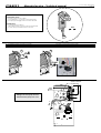
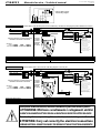
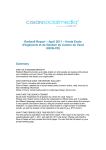
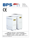
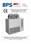
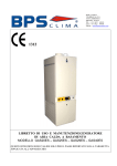
BPS S.r.l. - Via Biban (Zona Industriale), 56
31030 – CARBONERA ; TREVISO (ITALY)
Tel.: +39 0422-445363 r.a. - Fax.: +39 0422-398646
www.bpstecnologie.com
e-mail: [email protected]
Una linea completa di pannelli comando dedicati per installazione a
bordo unità che permette, spendendo poco di più, di avere tanto di più ...
A complete range of control panel dedicated to the unit’s on-board
installation which, with reasonable price, are offering much more…
CBE21
Manuale tecnico – Technical manual
Code: MT-CBE21- 80020132-R00
Page 1/3
COMPONENTI FORNITI
Quadro comando mod. CBE 21
(con OFF/Est/Inv + 3 velocità ; senza Termostato)
2 viti (A+B) per fissaggio staffa comando sull’unità
SUPPLIED ITEMS
Control panel mod. CBE 21
(with OFF/Sum/Win + 3 speed ; withouot Thermostat)
2 screws (A+B) to install the frame in the unit
Installare il quadro comando (2 viti: A+B)
Inserire il connettore unidirezionale del quadro comando sull’autotrasformatore dell’unita
1
Install the control panel (2 screws: A+B)
Insert the control panel one-way plug on the unit’s autotransformer
2
A
B
CLAK!
Quadro comando
Control Panel
Staffa
Bracket
165
95
1
2
A+B
A
Dettaglio dei 2 Fori (A+B) da usare
Detail of 2 holes (A+B) to be used
55
4=B
1 2 3 4 5 6 7 8 9
T
N
Ph
Autotrasformatore
Autotransformer
CBE21
Manuale tecnico – Technical manual
Code: MT-CBE21- 80020132-R00
Page 2/3
Comando a bordo unità elettronico con OFF/Estate/Inverno + 3 Velocità ,
senza termostato ambiente
Electronic control panel with OFF/Summer/Winter + 3 Speed , without
room thermostat
Comando idoneo per la gestione di unità a 3 velocità a 2 tubi, senza
valvole.
Questo comando controlla unità con e senza termostato di minima
temperatura acqua “TM” (Il “TM” è un accessorio addizionale).
Essendo questo comando sprovvisto di termostato interno, il controllo
della temperatura (se desiderato) dovrà essere realizzato tramite una
regolazione aggiuntiva indipendente.
Ideale per unità equipaggiate di “TM” e con pompa acqua
controllata da un termostato indipendente (in riscaldamento quando il
termostato aggiuntivo ferma la pompa acqua calda si ferma anche il
ventilatore ; in raffreddamento quando il termostato ferma la pompa
acqua fredda continua comunque una gradita ventilazione).
Control panel suitable to control 2 pipes system 3-speed units, without
valves.
This control panel can control units with or without “TM” water low
temperature thermostat (The “TM” is an additional option).
Since this control panel is not provided with internal thermostat, the
temperature control (if required) must be realised through an
additional independent regulation.
It is ideal for units equipped with TM and with water pump controlled
by independent thermostat (in heating mode when additional
thermostat stops the hot water pump also the ventilation is stopped ; in
cooling mode when the thermostat stops the cold water pump a
pleasant ventilation is maintained).
CARATTERISTICHE ELETTRICHE - ELECTRICAL FEATURES
Alimentazione elettrica
Power supply
Potenza assorbita
Power absorption
Campo di regolazione
Regulation range
Tipo di sensore
Sensor type
Precisione
Accuracy
Risoluzione
Resolution
Isteresi
Hysteresis
Portata contatti
Contact rating
Grado di protezione
Protection grade
Temperatura di funzionamento
Operating temperature
Temperatura di stoccaggio
Storage temperature
Limiti di umidità
Humidity limits
Contenitore
Case
Norme di riferimento EMC
EMC reference norms
Norme di riferimento LVD
LVD reference norms
230V~ -15% +10% / 1 Ph / 50 Hz
n.a.
n.a.
n.a.
n.a.
n.a.
n.a.
5 (1) A @ 250V~
IP 20
0 °C ÷ +40 °C
-10 °C ÷ +50 °C
20 % ÷ 80 % U.R. – R.H. (senza condensa - non condensing)
ABS
n.a.
CEI-EN 60335-1
CARATTERISTICHE FUNZIONALI
I comandi disponibili sul fronte del quadro comando per l’utente sono 2
selettori.
FUNCTIONAL FEATURES
The controls available on the front cover of the user’s control board are 2
sliders.
Selettore OFF/Estate/Inverno (Ventola/Off/Fiamma)
Tramite questo selettore a 3 posizioni si può disattivare od attivare il
motore dell’unità:
Modalità Off (0) : l’unità è spenta/disattivata.
Modalità raffreddamento (Ventola): è attivata la modalità
raffreddamento, by-passando l’eventuale termostato di minima “TM”
(equivale ad “ON”).
Modalità riscaldamento (Fiamma): è attivata la modalità
riscaldamento, controllata dall’eventuale termostato di minima “TM”
(qualora il “TM” non sia presente, equivale ad “ON”).
Il termostato di minima “TM” (esterno) agisce solo quando si imposta la
funzione riscaldamento (Fiamma).
Selettore 3 velocità motore
Tramite questo selettore a 3 posizioni si può scegliere la velocità (fissa) di
attivazione del motore dell’unità.
OFF/Summer/Winter selector (Fan/Off/Flame)
Through this 3-position slide selector, the user can choose to activate or
deactivate the unit’s motor:
Off function (0) : the unit is deactivated.
Cooling function (Fan): cooling function is activated, the “TM” water
low temperature thermostat is by-passed (equivalent to “ON”).
Heating function (Flame): heating function is activated and controlled
by the “TM” water low temperature thermostat if installed (if “TM” is not
installed, equivalent to “ON”).
The “TM” water low temperature thermostat (external) affects only
when the switch is in the heating function position (Flame).
Nelle pagine seguenti viene riportata una breve raccolta di schemi
elettrici (quelli che vengono richiesti ed utilizzati più frequentemente).
Qualora non sia disponibile lo schema elettrico necessario per uno
specifico impianto (o per un particolare sistema di regolazione),
ricordiamo che siamo sempre disponibili a realizzare ulteriori nuovi
schemi elettrici in accordo alle esigenze e richieste dei nostri clienti.
Per ulteriori informazioni rivolgersi al nostro ufficio tecnico che rimane a
disposizione per qualsiasi chiarimento e per la progettazione di soluzioni
personalizzate.
LEGENDA – TABLE OF REFERENCES
G/V
Fase (linea 230V-1Ph) – Phase (230V-1Ph line)
Ph
MA
Neutro (linea 230V-1Ph) – Neutral (230V-1Ph line)
N
BL
Terra – Earth
T
NE
Com Comune - Common
RO
Velocità Minima - Min. speed
I
BI
Velocità Media - Med. speed
II
GR
Velocità Massima - Max. speed
III
3-speed motor selector
Through this 3-position slide selector, the user can chose the (fixed) speed
of the unit’s motor.
In the hereby pages there is a basic electrical wiring diagrams listing
(most requested and used wiring diagrams are included).
May a wiring diagram for a specific installation not be available in the
present listing (or for a special particular need), we would like to remind
you that it can be realised according with your special needs.
For further information make reference to our Technical department,
which is available for explanations and for the design of customised
solutions.
Giallo/Verde - Yellow/Green
Marrone - Brown
Blu - Blue
Nero - Black
Rosso - Red
Bianco - White
Grigio - Grey
VI
AR
GI
VE
Viola - Violet
Arancione – Orange
Giallo - Yellow
Verde - Green
E – Est
I - Inv
Estate – Summer
Inverno – Winter
COMPONENTI FORNITI MONTATI – EQUIPMENTS SUPPLIED MOUNTED
STANDARD
ACCESSORI - ACCESSORIES
TM
Motore ventilatore centrifugo – Centrifugal fan motor
MVC
Termostato di minima temperatura acqua - Water low temperature thermostat
Condensatore - Capacitor
C
Autotrasformatore – Autotransformer
AUTR
Morsettiera tipo “Mamut” - “Mammoth” type terminal board
Mors1
COMPONENTI NON FORNITI – EQUIPMENTS NOT SUPPLIED
IG-2p
Interruttore magnetotermico generale (230V - 2 contatti: Fase, Neutro) - General magnetothermic switch (230V - 2 contacts: Phase, Neutral)
FRM
Fermacavo – Wire-stopper
CBE21
Manuale tecnico – Technical manual
Off
I
II
CBE21-A001-80029040-R00
2
3
4
5
7
1
MA
N
2
BL
1 2 3 4 5 6 7 8 9 10 11 12
DISPOSITIVI E MONTAGGIO A CURA DELL’INSTALLATORE
EQUIPMENTS TO BE INSTALLED BY THE INSTALLER
230V – 1Ph – 50Hz
DISPOSITIVI
A CORREDO
DELL’UNITÁ
G/V
M MA
M
BL
MVC
C
Le 3 velocità collegate
sull’autotrasformatore
(1=max – 2 – 3 – 4 – 5 – 6=min)
possono essere diverse di quelle
indicate sullo schema elettrico
(dipende dal modello)
The 3 speeds connected
to the autotransformer
(1=max – 2 – 3 – 4 – 5 – 6=min)
can be different from those
indicated on the wiring diagram
(depending on the model)
Working
Off:
All off ; All closed
Est.:
“MVC” Always on (not controlled by thermostat)
Inv.: “MVC” Always on (not controlled by thermostat)
Schema elettrico unità + Accessorio TM – Unit wiring diagram + Accessory TM
G/V
T
Ph
1
MA
N
2
BL
FRM
DISPOSITIVI E MONTAGGIO A CURA DELL’INSTALLATORE
EQUIPMENTS TO BE INSTALLED BY THE INSTALLER
230V – 1Ph – 50Hz
Com L (Com)
1(max)
III
RO
2
II
BI
3
4
I
MA
5
6(min)
BL
Mors1
IG-2p
Alimentazione
elettrica
Power supply
AUTR
EQUIPMENTS
INCLUDED
ON THE UNIT
Funzionamento
Off:
Tutto spento ; Tutto chiuso
Est.:
“MVC” Sempre acceso (non controllato dal termostato)
Inv.: “MVC” Sempre acceso (non controllato dal termostato)
230V – 1Ph – 50Hz
Com L (Com)
1(max)
III
RO
2
II
3
BI
4
I
MA
5
6(min)
BL
Ponte - Bridge
Mors1
IG-2p
CBE21-A002-80029040-R00
8
G/V
Ph
FRM
Alimentazione
elettrica
Power supply
L
6
Schema elettrico unità standard (senza accessori addizionali) – Standard unit wiring diagram (without additional accessories)
T
230V – 1Ph – 50Hz
Schema elettrico interno
Internal wiring diagram
III
N
1
Code: MT-CBE21- 80020132-R00
Page 3/3
1 2 3 4 5 6 7 8 9 10 11 12
DISPOSITIVI
A CORREDO
DELL’UNITÁ
EQUIPMENTS
INCLUDED
ON THE UNIT
MA
BL
Funzionamento
Off:
Tutto spento ; Tutto chiuso
Est.:
“MVC” Sempre acceso (non controllato dal termostato)
Inv.: “MVC” Sempre acceso (non controllato dal termostato) + intervento del TM
TM
AUTR
G/V
M MA
M
BL
MVC
C
Le 3 velocità collegate
sull’autotrasformatore
(1=max – 2 – 3 – 4 – 5 – 6=min)
possono essere diverse di quelle
indicate sullo schema elettrico
(dipende dal modello)
The 3 speeds connected
to the autotransformer
(1=max – 2 – 3 – 4 – 5 – 6=min)
can be different from those
indicated on the wiring diagram
(depending on the model)
Working
Off:
All off ; All closed
Est.:
“MVC” Always on (not controlled by thermostat)
Inv.:
“MVC” Always on (not controlled by thermostat) + TM action
Tenere presente che modifiche elettriche, meccaniche e manomissioni in genere fanno decadere la garanzia !!
ATTENZIONE: Effettuare correttamente i collegamenti elettrici
UN ERRATO COLLEGAMENTO ELETTRICO PROVOCA LA BRUCIATURA DEI DISPOSITIVI ELETTRICI DELL’UNITÁ !
Please do not forget that warranty cannot be applied in case of electric, mechanical and other general modifications !!
ATTENTION: Carry out correctly the electrical connections
A WRONG ELECTRICAL CONNECTION CAUSES THE BURNING OF THE UNIT ELECTRICAL EQUIPMENTS !