1
3 ph P.W.S.
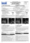
Schema elettrico
Wiring diagram
380-420/3/50
440-480/3/60
380-420/3/60
Collegamenti della morsettiera
Terminal connections
avviamento diretto DOL • Direct On Line start
avviamento frazionato PWS • Part Winding Start
Serie S - V - Z - W Series
Serie S - V - Z - W Series
Z7
U1
X8
Y9
V2
X8
Y9
U1
V2
W3
W3
U aux (---L3)
L3
I
L1
L2
L3
Z7
B
A
HS
N
F
L
F
1
2
11
K1
L3
N
N
12
14
PT
TR4
TR3
PT
DT
PT
PT
DP
P
M
3~
LP1
N
A
TR3
TR3
T5
TR4
TR3
T5
TR4
TR4
N aux (---N)
B
*
Potenza del teleruttore ≥ 0.65 x massima potenza assorbita
Contactor power ≥ 0.65 x maximum input power
**
Portata dei fusibili (tipo aM) = 1.1 ÷ 1.3 x MRA (vedi targhetta del compressore)
Fuses capacity (aM type) = 1.1 ÷ 1.3 x MRA (see name plate on the compressor)
Non alimentare direttamente
i terminali A - B dei termistori
Do not feed directly terminals
A - B of the thermistors
Legenda schemi elettrici - Wiring diagrams key
A-B
DP
DT
F
HS
I
K
K1
LP1
M041-08
terminali dei termistori
pressostato
termostato di regolazione
fusibile **
sensore max. temperatura di compressione
interruttore di linea
piastra terminali
modulo elettronico KRIWAN
spia intervento termistori
thermistor terminals
pressure switch
temperature switch
fuse **
max discharge temperature sensor
main switch
terminal board
KRIWAN electronic module
thermistor warning lamp
L1
L2
L3
N
PT
TR3
TR4
T5
fase della rete di alimentazione
fase della rete di alimentazione
fase della rete di alimentazione
neutro
protettore termoamperometrico
teleruttore avviamento 50%
teleruttore avviamento 100%
relay temporizzato 0.5-1 sec
phase of electrical net
phase of electrical net
phase of electrical net
neutral
overload protector
starting contactor 50%
starting contactor 100%
timer relay 0.5-1 sec.
5