1
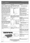
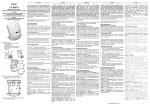
IR 360 Infrarosso 360° ISTRUZIONI DI INSTALLAZIONE Funzionamento Montaggio • Copertura Massima (diametro) Rilevatore posizionato a 2,4 m da terra: 7,3 m Rilevatore posizionato a 3,0 m da terra: 9,2 m Rilevatore posizionato a 3,6 m da terra:12,2 m • Modalità di funzionamento aggiuntivo LED Acceso/Spento Ponticello J1 Conteggio impulsi (Veloce/Lento) Ponticello J2, J2 inserito (ON) = Veloce Per aprire il rivelatore, togliere la vite di fissaggio quindi girare la calotta in senso antiorario per separarla dal fondo. Con un piccolo cacciavite a taglio, forare la plastica e staccare le sezioni predisposte per il passaggio dei cavetti di collegamento. Fissare il rilevatore con delle viti appropriate (non fornite). Per chiudere la calotta, allineare la linea sul fondo dell'alloggiamento con la linguetta sulla calotta quindi girare la calotta in senso orario per completare il montaggio. NOTA - Poiché non è necessaria nessun regolazione del circuito stampato, è consigliabile non rimuoverlo dell'alloggiamento. L'IR360 è un rilevatore infrarosso passivo per il montaggio a soffitto, appositamente studiato e realizzato per assicurare una protezione ottimale in applicazioni domestiche e commerciali. L'IR360 utilizza un sofisticato lente Fresnel che fornisce una copertura di 360° e un sensore infrarosso passivo ad elemento quadruplo ottimizzato per garantire il massimo gradi di rilevazione. L'IR360 minimizza l'incidenza di falsi allarmi e garantisce un eccellente grado di immunità ai disturbi RF, ai transienti ed alle scariche elettrostatiche per garantire un uso negli anni senza probemi. Ambiente/Immunità Descrizione Per i diagrammi Vista in pianta (a 2,4 m altezza) e Vista Laterale vedere rispettivamente le Fig. 1 e 2. Al momento della messa in funzione, il LED si accenderà per circa 90 secondi per indicare che il dispositivo è in fase di stabilizzazione. Durante questo tempo, il relè sarà in condizione di allarme. Trascorsi 90 secondi, il LED si spegnerà per indicare che il dispositivo è in grado di rilevare movimento all'interno dell'area di copertura. Posizionamento del Rilevatore Modalità Test (J1) L'IR360 è appositamente studiato e realizzato per montaggio a soffitto in un luogo asciutto e al coperto per una copertura di 360°. Assicurare che il presunto percorso di violazione sia perpendicolare al fascio di rilevazione. Utilizzare la schema di copertura (vedere il diagramma di copertura) per determinare il posizionamento migliore. Scrutare il punto di montaggio e l'area di proteggere per i seguenti potenziali disturbi. Evitare i seguenti cause di falsi allarmi. NOTA - Dopo l'installazione, e necessario sottoporre il rivelatore a una prova di corretto funzionamento (Walk Test). Il corretto funzinament del rilevatore dovrebbe essere verificato settimanalmente dell'utente, e annualmente dell'installatore. • • • • • • • • • • Multi-Level Signal Processing (Brevettato) Copertura di 360° Sensore infrarosso passivo ad elemento quadruplo Protezione ottimale ai transienti e alle scariche elettrostatiche Eccellente grado di immunità a RF Compensazione termica Ponticello per la rilevazione Veloce/Lenta Ponticello per Abilitazione/Disabilitazione LED Fabbricazione SMD Funzionamento silenzioso • • • • Collegamenti Immunità RF: 20V/m ( 100Hz - 1,2GHz) Immunità ai transienti @ morsetto: 2,4KV @ 1,2joules Temperatura di funzionamento: 32 -122°F / 0 - 50°C Umidità 5 - 95% RH senza condensazione Vedere la Fig. 3 La messa in funzione Coperatura Walk Test Specifiche Flusso d'aria Elettriche Evitare di collocare il rilevatore in luoghi sottoposti a forti correnti d'aria, come vicino alle uscite dell'aria condizionata. Creare movimento all'interno dell'area di copertura. Il LED si accenderà ogni volta che viene raggiunta la condizione di allarme (ponticello J1 inserito). Se la copertura risulta inadeguata, cambiare la posizionamento del rilevatore. Per ottenere una lieve modifica della sensibilità, ruotare il rilevatore leggermente. Per una copertura ottimale, fare riferimento agli schemi di copertura (Fig. 1 e 2). Una volta completata la prova, il LED del "Walk Test" può essere disabilitato rimuovendo il ponticello J1. • Tensione di alimentazione: 9 - 14,5 V_ • Corrente (Nominale): 18/15 mA (in allarme / a riposo) @12 V_ Umidità Regolazione della sensibilità (J2) Contatti Raggi solari • Relè di Allarme: 0,1A @24V_ • Deviatore Antisabottaggio: 0,1A @24V_ Non puntare il rilevatore su superfici riflettenti come specchi o finestre che potrebbero riflettere i raggi solari direttamente sul rilevatore. Dimensioni (diametro x altezza) 117 mm x 36 mm Superfici riflettenti Non puntare il rilevatore su superfici riflettenti come specchi o finestre, poiché possono distorcere l'area di copertura o riflettere i raggi solari direttamente sul rilevatore. Non montare il rilevatore nei pressi di fonti di umidità come vapore o carburante. L'IR360 è dotato di un ponticello (vedi J2, POnticello Sensibilità, fig. 4) che permette di scegliere l'impostazione del modalità di rilevazione (Veloce o Lenta). Il ponticello J2 è preimpostato in fabbrica in modalità di rilevazione Veloce (Vedere Fig. 4): questa è la modalità che più si adatta alla maggiorparte degli ambienti. Per un ambiente che presenta potenziale disturbo, come stanze sottoposte a forti correnti d'aria o fonti di calore, ecc., è più addatta la modalità Lenta, perciò sarà necessario rimuovere il ponticello J2 per stabilizzare la rilevazione. Ostacoli Non limitare la copertura con oggetti di grandi dimensioni come piante, scaffali o armadietti che impediscono il corretto funzionamento del dispositivo. 3,5 6(1625 Fig. 2 - Vista laterale Fig. 1 - Vista in pianta 7$03(5 6:,7&+ Fig. 3 - Collegamenti Fig. 4 - Fondo ISTISBL1IR360 0.1 020904 P70 Operation Mounting • Maximum detection range (diameter) Detector placed 8 ft./ 2.4 m from floor: 24 ft./ 7.3 m Detector placed 10 ft./ 3.0 m from floor: 30 ft./ 9.2 m Detector placed 12 ft./ 3.6 m from floor: 40 ft./ 12.2 m • Additional operating modes LED ON/OFF Jumper J1 Pulse count (fast/slow) Jumper J2, J2 ON is fast count. To open the case, remove the securing screw from the unit then twist the top cover counter-clockwise and lift it up from the bottom cover. Use a small screwdriver to remove the appropriate knockouts for wiring. Mount the backplate using the appropriate mounting screws (not provided). To close the case, use the locating line on the bottom cover to align the tab on the top cover. Once the top cover is engaged, twist the top cover clockwise to lock it in place. The IR360 is a ceiling mount detector designed to provide reliable motion detection for residential and commercial applications. The IR360 uses a special Fresnel lens made for 360° detection in conjunction with a quad element PIR sensor optimized for uniform detection all around its field of view. Special attention is given to false alarm immunity against RF, static, electrical transient to ensure trouble free operation for many years. Environmental/Immunity NOTE: Since no adjustment is necessary for the circuit board, it is not recommended that the installer remove the circuit board from the case. Features Coverage • • • • • • • • • • See Fig. 1 and 2. IR 360 Ceiling Mount PIR Detector INSTALLATION INSTRUCTIONS Multi-Level Signal Processing (Patented) 360° coverage Quad element PIR sensor High level static and transient protection Excellent RF immunity Temperature compensation Fast/Slow detection jumper LED ON/OFF jumper SMD construction Super quiet operation • • • • RF Immunity: 20V/m ( 100Hz - 1.2GHz) Transients @ wiring terminal: 2.4KV @ 1.2joules Operating temperature: 32 -122°F / 0 - 50°C Humidity 5 - 95% RH non-condensing Wiring See Fig. 3 for wiring instructions. Power Up Upon application of power, the LED will be on for approximately 90 seconds to indicate that the unit is warming up. During this period, the relay is held in its alarm state. After the 90 second warm-up period, the LED will turn off and the unit will respond to motion in the protected area. Locating the Detector The IR360 is designed to be mounted on the ceiling of a dry indoor location for 360° coverage. Ensure that the expected path of an intruder is perpendicular to the beam path. Use the coverage pattern indicated on the coverage diagram to determine the best sensor location. Survey the mounting location and the area being protected for the following potential problems. Avoid the following sources of false alarms: Specifications Do not aim the detector at reflective surfaces such as mirrors or windows as this may distort the coverage pattern or reflect sunlight directly onto the detector. Electrical Air Flow • Input Voltage: 9 - 14.5 V_ • Current (nominal): 18/15 mA (alarm on/off) @12 V_ Avoid locations that are subject to direct high air flow such as near an air duct outlet. Moisture Contact Rating Do not locate the detector near sources of steam or oil. • Alarm Relay: 0.1A @24V_ • Tamper Switch: 0.1A @24V_ The Sun Create movement in the entire area where coverage is needed. The LED on the unit will turn on whenever motion is detected (jumper J1 must be on). If coverage is incomplete, relocate the unit. You can make minor adjustments by rotating the detector several degrees. Refer to the coverage pattern diagrams as a guide to reposition the detector for better coverage. Once the detector coverage is as required, you may turn off the alarm LED by removing the jumper from J1. Changing the Sensitivity Do not aim the detector such that it will receive direct sunlight. Obstructions 4.6" x 1.4" / 117 mm x 36 mm IMPORTANT NOTE: Upon installation, the unit should be thoroughly tested to ensure proper working order. The detector should be walk tested weekly by the user and annually by the installer. Walk Test Reflective Surfaces Size (diameter x height) Testing Do not limit the coverage by placing large objects within the detection area (such as plants, high shelves, filing cabinets etc.). IR360 features Fast and Slow detection modes, which are set on jumper J2. Jumper J2 is set at the factory for the Fast detection mode (See Fig. 4). In a normal operating environment, this setting provides the best detection. In certain environments where rapid air movement, heaters and other variables present problems, use Slow detection mode to stabilize the detection. To change the setting from Fast to Slow, take the jumper off the header. # 3,5 6(1625 !" 090.947!,99073 Fig. 1 - Top View 7$03(5 6:,7&+ Fig. 2 - Side View Fig. 3 - Wiring Fig. 4 - Back Plate ISTISBL1IR360 0.1 020904 P70