1
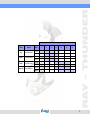
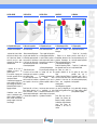
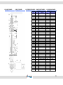
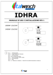
Manuale di installazione e uso
Installation and user’s manual
Manuel d’installation ed d’utilisation
Installation und Nutzung
Uputstvo za upotrebu i ugradnju
RAY – THUNDER
1
www.italwinch.com
Rev.01
Dužina Plovila (m)
Model
Materijal
Ray
Anodizirani Aluminij
Ray Lux
Kromirana Bronca
Thunder
Anodizirani Aluminij
Thunder Lux
Kromirana Bronca
Snaga
6
8
10
12
14
16
18
500 W
700 W
500 W
700 W
1000 W
1400 W
1000 W
1400 W
2
INDICE
TABLE OF CONTENTS
1 INTRODUZIONE
4
1.1 Scopo del manuale
1.2 Assistenza
1.3 Conformità CE
1.4 Ricevimento e stoccaggio
1.5 Nota importante
4
4
4
4
4
2 INSTALLAZIONE
5
2.1 Contenuto della confezione
2.2 Attrezzature necessarie per
l’installazione
2.3 Accessori consigliati
2.4 Preparazione della coperta
2.5 Installazione in coperta
2.6 Installazione sotto coperta
5
5
5
6
7
8
3 IMPIANTO ELETTRICO
9
3.1 Scelta dei cavi
3.2 Connessioni
3.3 Schema di collegamento
9
9
10
4 USO DEL SALPA ANCORA
11
4.1 Uso della frizione
4.2 Uso del motore
4.2.1 Filare l’ancora
4.2.2 Salpare l’ancora
4.3 Uso della campana
11
12
12
12
13
5 MANUTENZIONE ORDINARIA 14
6 DATI TECNICI
15
7 DIMENSIONI
16
8 LISTA PARTI RAY / RAYLUX 17
9 LISTA PARTI THUNDER /
THUNDER LUX
18
10 CONDIZIONI DI GARANZIA 19
11 TARGHETTA
IDENTIFICAZIONE PRODOTTO 20
INDEX
SADRžAJ
INHALTSVERZEICHNIS
1 INTRODUCTION
4
1 INTRODUCTION
4
1 EINLEITUNG
4
1 UVOD
4
1.1 Purpose of the manual
1.2 Product support
1.3 CE approvals
1.4 Receipt and storage
1.5 Important note
4
4
4
4
4
1.1 Objectif du manuel
1.2 Soutien Technique
1.3 Agrément CE
1.4 Réception et stockage
1.5 Informations importantes
4
4
4
4
4
1.1 Zweck des Handbuchs
1.2 Produktunterstützung
1.3 CE Zulassung
1.4 Empfang und Lagerung
1.5 Wichtige Informationen
4
4
4
4
4
1.1 Svrha priručnika
1.2 Pomoć
1.3 CE odobrenja
1.4 Preuzimanje i skladištenje
1.5 Važna napomena
4
4
4
4
4
2 INSTALLATION
5
2 INSTALLATION
5
2 MONTAGE
5
2 UGRADNJA
5
2.1 Contents of the package
2.2 Equipment necessary for
Installation
2.3 Recommended accessories
2.4 Above deck preparation
2.5 Deck installation
2.6 Under deck installation
5
5
5
5
6
7
8
2.1 Contenu de l’emballage
2.2 Outillage nécessaire à
l’installation
2.3 Accessoires conseillées
2.4 Préparation sur le pont
2.5 Installation sur le pont
2.6 Installation sous le plancher
2.1 Packungs-Inhalt
5
2.2 Für die Installation benötigte
Werkzeuge
5
2.3 Empfohlenes Zubehör
5
2.4 Vorbereitungen auf Deck
6
2.5 Auf deck installation
7
2.6 Unter deck installation
8
2.1 Sadržaj kutije
2.2 Nužna oprema za ugradnju
2.3 Preporučeni pribor
2.4 Priprema palube
2.5 Ugradnja na palubi
2.6 Ugradnja ispod palube
5
6
6
7
7
8
3 ELECTRICAL WIRING
9
3 ELEKTRIčNI VOD
9
3 INSTALLATION ELECTRIQUE 9
3 ELEKTRISCHE MONTAGE
9
3.1 Electric cable selection
3.2 Wiring
3.3 Wiring diagram
9
9
10
3.1 La sélection du câble
3.2 Câblage
3.3 Schéma de branchement
3.1 Auswahl elektrische Kabel
3.2 Verkabelung
3.3 Anschluss-Schaltplan
9
9
10
3.1 Izbor kablova
3.2 Ožičenje
3.3 Shema spajanja
9
9
10
4 USE OF THE WINDLASS
11
4 UPOTREBA VITLA
11
4 UTILISATION DU GUINDEAU 11
4 BEDIENUNG
11
4.1 Braked anchor free-fall
4.2 Power up/down
4.2.1 Release the anchor
4.2.2 Retrive the anchor
4.3 Use of the warping drum
11
12
12
12
13
11
12
12
12
14
12
12
12
12
13
4.1 Gebremstes Anker fieren
11
4.2 Motorisiertes Heben und
Fieren
12
4.2.1 Fieren des Ankers
12
4.2.2 Heben des Ankers
12
4.3 Verwendung des Verholspills 13
4.1 Upotreba kvačila
4.2 Upotreba motora
4.2.1 Spuštanje sidra
4.2.2 Podizanje sidra
4.3 Upotreba bubnja/zvona
13
5 SERVICING SCHEDULE
4.1 La chute libre contrôlée de
l’ancre
4.2 Opération montée/descente
4.2.1 Larguer l’ancre
4.2.2 Remonter l’ancre
4.3 Utilisation de la poupée
5 PLAN ODRžAVANJA
14
6 TECHNICAL DATA
15
5 PLANNING D’ENTRETIEN
14
5 SERVICE INTERVALLE
14
6 TEHNIčKI PODACI
15
7 DIMENSION
16
6 DONNEES TECHNIQUE
15
6 TECHNISCHE ANGABEN
15
7 DIMENZIJE
16
8 PART LIST RAY / RAY LUX 17
7 SPECIFICATION
16
7 ABMESSUNGEN
16
9 PART LIST THUNDER /
THUNDER LUX
8 LISTE DES PIECES RAY / RAY
LUX
17
18
10 WARRANTY CONDITIONS 19
11 PRODUCT IDENTIFICATION 20
5
5
6
7
8
9
9
10
9 LISTE DES PIECES THUNDER /
THUNDER LUX
18
10 CONDITIONS DE GARANTIE 19
11 IDENTIFICATION DU
PRODUIT
8 BAUTEILE-LISTE RAY /
RAY LUX
17
9 BAUTEILE-LISTE THUNDER /
THUNDER LUX
18
8 LISTA DIJELOVA RAY / RAY
LUX
17
9 LISTA DIJELOVA THUNDER /
THUNDER LUX
18
10 GARANTIEBEDINGUNGEN 19
10 UVIJETI GARANCIJE
11PRODUKTBEZEICHNUNG
11 IDENTIFIKACIJSKA PLOčICA
PROIZVODA
20
20
19
20
3
1 INTRODUZIONE
1 INTRODUCTION
1 INTRODUCTION
1 EINLEITUNG
1 UVOD
Gentile Cliente,
grazie per aver scelto Italwinch.
I prodotti Italwinch garantiscono
qualità, tecnologia ed elevate
prestazioni.
Con un prodotto Italwinch si è sicuri
di anni di affidabile funzionamento.
Dear Customer,
Thank you for choosing Italwinch.
Italwinch
products
guarantee
quality, technical innovation and
proven performance.
With a Italwinch product you will be
provided with many years of
outstanding service.
Cher Client,
Merci d’avoir choisi un guindeau
Italwinch. Les produits Italwinch
sont
garantie
de
qualités,
innovations
techniques
et
performances. Avec Italwinch vous
êtes assuré de nombreuses années
de service exceptionnel.
Vielen Dank für die Wahl einer
Italwinch. Italwinch Produkte sind
garantiert für Qualität, technische
Innovation und Leistungsfähigkeit.
Mit einer Italwinch Schotwinsch
steht Ihnen für viele Jahre ein
erstklassiger Service zur Verfügung.
Poštovani kupče,
Hvala što ste izabrali Italwinch.
Proizvodi
Italwinch
garantiraju
kvalitetu, tehnologiju I vrhunske
performanse. Proizvodi Italwinch
imaju godine pouzdanoga rada.
1.1 Purpose of the manual
1.1 Objectif du manuel
This manual will supply information
about safety and correct use of the
product. Follow these warnings
carefully to avoid possible accidents
or damages.
Dans ce manuel, vous trouverez les
informations concernant la sécurité
et la bonne utilisation du produit.
Suivre
attentivement
ces
avertissements à éviter de se
blesser ou de détériorer l’appareil.
Mit diesem Handbuch werden
Informationen zur Sicherheit und
der richtigen Verwendung des
Produktes
gegeben.
Diese
Hinweise sorgfältig einhalten, um
mögliche Unfälle und Schäden zu
vermeiden.
1.2 Soutien Technique
1.2 Produktunterstützung
Les produits Italwinch jouissent d’un
réseau d’assistance à travers le
monde entier, par le biais de ses
distributeurs. En cas de besoin,
contacter le distributeur local
Italwinch. Voir les détails sur le site
www.italwinch.com
Für die Produkte Italwinch gibt es
ein weltweites Netz von Händlern.
Setzten Sie sich gegebenenfalls mit
dem örtlichen Händler der Italwinch
in Verbindung. Einzelheiten auf der
Internetseite www.italwinch.com
1.1 Scopo del manuale
Attraverso
questo
manuale
verranno date informazioni relative
alla sicurezza e al corretto utilizzo
del prodotto. Seguire attentamente
queste avvertenze in modo da
evitare
possibili
infortuni
o
danneggiamenti.
1.2 Assistenza
Tutti i prodotti Italwinch godono
della rete di assistenza mondiale
Italwinch.
Per qualsiasi necessità, contattare
direttamente il distributore locale o
visitare il sito www.italwinch.com
1.3 Conformità CE
1.2 Product support
All Italwinch products are backed
throughout the world by a network
of authorised distributors and
assistance. In case of need, please
contact
our
local
Italwinch
distributor.
Details
on
website
www.italwinch.com
1.3 CE approvals
1.3 Agrément CE
For CE approval certificates contact
Italwinch.
Pour obtenir les certificats CE
veuillez contacter Italwinch.
1.4 Ricevimento e stoccaggio
1.4 Receipt and Storage
1.4 Réception et Stockage
Al ricevimento della confezione,
verificare l’integrità dell’imballo. In
caso sia necessario immagazzinare
il prodotto per un lungo periodo,
mantenere in luogo asciutto e
protetto.
Upon receipt of the package, verify
the integrity of packing. Should it be
necessary to store the product for a
prolonged period, keep it in a dry
and protected place.
A la réception de la marchandise,
vérifier le bon état de l’emballage.
Si le produit doit être emmagasiné
durant une période prolongée, le
conserver dans un endroit sec et
abrité.
I certificati di conformità CE sono
disponibili contattando Italwinch.
1.5 Nota importante
Nel presente manuale sono presenti
avvertimenti importanti per la
sicurezza.
Attenersi scrupolosamente ad essi
per evitare danni o infortuni.
1.5 Important note
Throughout
see safety
warnings.
You must
carefully to
damage.
this manual, you will
and product damage
follow these warnings
avoid possible injury or
1.5 Informations importantes
Dans ce manuel vous allez voir des
mises en garde de sécurité et des
précautions d’emplois. Vous devez
suivre
attentivement
ces
instructions
afin
d’éviter
de
possibles accidents ou dommages.
1.1 Zweck des Handbuchs
1.3 CE Zulassung
Für ein CE Zertifikat kontaktieren
Sie bitte Italwinch.
1.4 Empfang und Lagerung
Beim Empfang der Packung die
Verpackung
auf
Schäden
überprüfen. Muss das Produkt für
längere Zeit gelagert warden an
einem trockenen und geschützten
Ort aufbewahrt werden.
1.5 Wichtige Informationen
In dieser Anleitung finden Sie
Sicherheitshinweise
und
Informationen,
um
eine
Beschädigung des Produktes zu
vermeiden. diesen Anweisungen
folgen, um mögliche Verletzungen
oder Schäden.
1.1 Svrha priručnika
Putem ovoga priručnika dobiti će se
informacije o sigurnosti i pravlinom
korištenju
proizvoda.
Pažljivo
slijediti upozorenja da bi se izbjegle
moguće ozljede ili oštećenja.
1.2 Pomoć
Svi proizvodi Italwinch su dostupni u
cijelom svijetu putem ovlaštenih
predstavnika. U slučaju nužde,
kontaktirajte
lokalnog
Italwinch
predstavnika. Detalje potražite na
web stranici www.italwinch.com
1.3 CE Odobrenja
Za CE odobrenja
Italwinch.
obratiti
se
1.4 Preuzimanje i skladištenje
Kod primanja proizvoda, provijeriti
stanje
ambalaže.
Ukoliko
je
potrebno proizvod uskladištiti na
neko duže vrijeme, čuvati ga na
suhom i očuvanom mjestu..
1.5 Važna napomena
U ovom priručniku se nalaze
upozorenja vezana za sigurnost.
Pridržavati se tih upozorenja kako bi
se spriječila oštećenja ili moguće
ozljede.
4
2 INSTALLAZIONE
2 INSTALLATION
2 INSTALLATION
2 MONTAGE
2 UGRADNJA
2.1 Contenuto della confezione
2.1 Contents of the package
2.1 Contenu de l’emballage
2.1 Packungs-Inhalt
21 Sadržaj ambalaže
Oltre al presente manuale, la
confezione contiene:
- salpa ancora completo di
motoriduttore
- Cassetta teleruttori/teleinvertitori
- Dima di foratura
- Leva
- Viteria
In addition to the present manual,
the package contains:
- Anchor windlass complete with
motor reducer
- Remote control switch/remote
control reverser box
- Drilling template
- Handle
- Screws
Outre ce manuel, l’emballage
contient:
- un guindeau avec son
motoréducteur
- Un boitier de télérupteurs/téléinverseurs
- Gabarit de perçage
- Levier
- Visserie
Die Packung enthält, außer dem
vorliegenden Handbuch, folgendes:
- Ankerwinde komplett mit
Getriebemotor
- Kasten Fernrelais/ Fernumschalter
- Bohrschablone
- Hebel
- Schraubensatz
Osim ovoga priručnika, kutija sadrži:
- Vitlo i reduktor motora
- Kontrolna kutija
- Shema bušenja
- Ručka
- Odgovarajući vijci
2.2 Equipment necessary for
installation
2.2 Outillage nécessaire à
l’installation
2.2 Für die Installation benötigte
Werkzeuge
- Drill
- 10 mm bit for wood and steel
- 10 mm., 13 mm., and 17 mm.
hexagon keys
- Crimping Pliers/Wire Stripper
- Suitable electrical cable and crimp
terminals
- Perceuse
- Foret de 10 mm pour bois et acier
- Clés à six pans de 10 mm, 13 mm
et 17 mm
- Pince à sertir/outil à dénuder
- Câbles électriques et cosses à
Sertir adaptés
- Bohrer
-10mm-Bohrspitze für Holz
undMetall
- Sechskantschlüssel mit 10 mm, 13
mm und 17 mm
- Crimp Zange/Abisolierzange
- Passende Crimp-Terminals und
entsprechende Kabelgrößen
- Bušilica
- Svrdlo 10 mm za drvo i čelik
- Šeterokutni ključevi od 10 mm, 13
mm i 17 mm
- Klješta za terminale i kombinirke
- Električni kabe i terminali na
prešu.
2.3 Accessori consigliati
2.3 Recommended accessories
2.3 Accessoires conseillés
2.3 Empfohlenes Zubehör
Utilizzare esclusivamente accessori
e ricambi originali MZ Electronic,
progettati e costruiti in modo da
assicurare prestazioni e durata. Per
informazioni
sugli
accessori
disponibili, rivolgersi al rivenditore
locale
o
visitare
il
sito
www.italwinch.com
Use
exclusively
original
MZ
Electronic accessories and spare
parts, designed and manufactured
to ensure performances, duration
and for keeping valid the warranty.
For information on available spare
parts, contact your local reseller or
visit website www.italwinch.com
Utiliser
exclusivement
les
accessoires et les pièces détachées
originales MZ Electronic, conçues et
fabriquées de façon à garantir les
performances, la longévité et la
validité de la garantie. Pour de plus
amples informations sur les pièces
détachées disponibles, s’adresser
au revendeur local ou visiter le site
www.italwinch.com
Ausschließlich
Original-Zubehör
und Ersatzteile des Unternehmens
MZ Electronic verwenden, das so
entwickelt und hergestellt wurde,
dass Leistung, Haltbarkeit und
Gültigkeit
der
Garantie
sichergestellt
werden.
Für
Informationen
zu
erhältlichen
Ersatzteilen, wenden Sie sich bitte
an den örtlichen Händler oder
besuchen Sie die Internetseite
www.italwinch.com
2.2 Attrezzature necessarie per
l'installazione
- Trapano
- Punta da 10 mm per legno e .
acciaio
- Chiavi esagonali da 10 mm, 13
mm e 17 mm
- Pinza per terminali e spellafili
- Cavo elettrico e terminali a
pressare
2.2 Potrebna oprema za ugradnju
2.3 Preporučeni pribor
Koristiti isključivo pribor i rezervne
djelove MZ Electronic, projektirani i
izrađeni na način da osiguraju
trajnost i izvedbu. Za informacije o
raspoloživom priboru, obratiti se
ovlaštenom predstavniku ili na web
stranici www.italwinch.com
5
2 INSTALLAZIONE
2 INSTALLATION
2 INSTALLATION
2 MONTAGE
2 UGRADNJA
2.4 Preparazione della coperta
2.4 Above deck preparation
2.4 Préparation sur le pont
2.4 Vorbereitungen auf Deck
2.4 Priprema palube
Verificare la zona di installazione:
Plan location carefully:
Prévoir l’endroit soigneusement :
Planen
sie
Montageort:
- assicurarsi che la leva di sblocco
della frizione sia libera di ruotare,
che il barbotin lavori allineato al
musone di prua, che lo spazio
sottocoperta sia sufficiente per la
caduta della catena
- Make an accurate drilling template
using the product dimensions from
the dimension template and decide
upon a position for it with reference
to the vessel’s bow roller and the
chain locker below and the rotation
of manual operating handle.
- Faire un gabarit de forage précis
en utilisant le gabarit de dimensions
du produit. Décidez la position en
tenant compte du réa de davier en
dessous ainsi que la rotation de la
manivelle manuelle.
- assicurarsi che la zona di
installazione sia piana e con
spessore costante.
Se la superficie di appoggio non
fosse piana, prevedere una base
che compensi il dislivello.
L’eventuale base di appoggio deve
essere modellata in modo che il
piano di appoggio del verricello sia
perfettamente parallelo al piano di
appoggio sottocoperta.
L’installazione in aree dove la
coperta è particolarmente sottile
oppure in presenza di sandwich di
balsa o schiuma, sarà necessario
prevedere adeguati rinforzi della
zona di fissaggio.
- Select a flat area of deck.
If the deck is not flat, a suitable
mounting pad may be required to
take up camber or sheer.
If a pad is required care must be
taken to ensure that the windlass
base is parallel to the over deck
plane.
Decks that are thin, or of foam or
balsa laminate construction, will
require reinforcement in order to
spread the loads that will be applied
to the deck while the windlass is in
use.
- utiliser une partie planedu pont.
Si le pont n’est pas plat, un bossage
de montage sera peut être
nécessaire.
Si un bossage est nécessaire pour
ces
modèles,
vérifiez
soigneusement que la base du
guindeau est parallèle à tablier de
plancher.
Les ponts trop minces, en mousse
ou
contreplaqué
de
balsa
nécessitent un renforcement afin de
repartir la charge sur le pont quand
le guindeau est en utilisation.
sorgfältig
den
- Erstellen sie ein akkurate
Bohrschablone basierend auf den
physischen
Abmessungen
der
Tabelle und entscheiden sich damit
für den gewünschten Montageort in
Relation zur Bugrolle des Schiffes,
dem Ankerkasten unter Deck und
dem Radius der Kurbel im
manuellen Notbetrieb auf der
Winde.
- Wählen sie eine ebene Fläche an
Deck. Wenn keine ebene Fläche
vorhanden ist, dann kann der
Einsatz
eines
Ausgleichskeils
notwendig werden.
Jeder Untergrund muss so gestaltet
sein, dass die Auflagefläche der
Winde Linie völlig parallel zur Platte
Deck ist.
Provjeriti prostor za ugradnju:
- Provjeriti
prostora za
lanac ulazi u
ima dovoljno
za lanac.
da li ima dovoljno
koristiti ručku, da li
barbotin po liniji i da li
prostora ispod palube
- Provjeriti da li je paluba ravna,
dovoljno debela i snažna .
Ako paluba nije ravna, treba
predvidjeti
bazu
koja
bi
kompenzirala razliku. Baza bi
trebala biti izrađena na način da
bude savršeno paralelna potpornoj
bazi ispod palube.
.
Ako je paluba slabija, od laganog
drva ili pjene, potrebno je ojačati
prostor predviđen za ugradnju.
Dünne Decks oder solche mit
Sandwich Kern (Schaum oder
Balsaholz) benötigen zusätzliche
Verstärkungen, um die auftretenden
Lasten
beim
Einsatz
der
Ankerwinde in das Deck zu
verteilen.
6
2 INSTALLAZIONE
2 INSTALLATION
2 INSTALLATION
2 MONTAGE
2 UGRADNJA
2.5 Installazione in coperta
2.5 Deck installation
2.5 Installation sur le pont
2.5 Auf deck installation
2.5 Ugradnja na palubi
- Posizionare con cura la dima di
foratura sul ponte assicurandosi del
corretto allineamento con la prua
dopo aver verificato ingombri e
spessori e aver verificato la scala
della dima.
- Place carefully the drilling template
on the deck, by ensuring the correct
alignment with the bow, after you
have checked all the above and
below deck requirements cut the
following holes.
- Positionner soigneusement le
gabarit de perçage sur le pont, en
s’assurant qu’il est bien dans l’axe
de la proue, après avoir vérifié tous
les critères sur et sous le pont,
découper les trous suivants.
- Nakon oslobađanja palube od
predmeta i pukotina, pozicionirati
“nacrt” bušenja u ravnini sa
pramcem..
- Rimuovere la dima solo dopo che
tutti i fori sono stati effettuati.
Applicare uno strato di sigillante
all’interno di tutti i fori per prevenire
l’infiltrazione di acqua nella struttura
dalle pareti.
- When all the holes have been
made, remove the template. To help
avoid water absorption by the deck,
apply an appropriate marine sealant
to the freshly cut hole edges.
- Quand tous les trous sont percés,
enlever le gabarit. Pour éviter
l’absorption de l’eau par le pont,
appliquer un mastic marin approprié
sur les bords des trous fraîchement
découpés.
- Die Bohrschablone sorgfältig auf
dem
Deck
positionieren.
Sicherstellen, dass sie richtig auf
den Bug ausgerichtet ist, Sägen
und Bohren der notwendigen
Löcher nach der Sicherstellung der
oben aufgeführten Punkte auf und
unter Deck.
- Posizionare con cura la parte
superiore del salpa ancora sulla
coperta.
- Fissare il salpa ancora.
- Collegare i cavi provenienti dalla
batteria al motore elettrico facendoli
passare per le aperture presenti sul
corpo riduttore.
- Place carefully the upper part of
anchor windlass on the deck.
- Fix the anchor windlass.
- Connect the wires from the battery
to the electrical engine by passing
them out through the openings in
the gearbox body.
- Positionner soigneusement la
partie superieure de le guindeau sur
le plancher.
- Fixer le guindeau.
- Brancher les câbles de la batterie
sur le moteur électrique, en les
faisant passer par les ouvertures
prévues sur le corps du réducteur.
- Wenn alle Bohrungen eingebracht
wurden
entfernen
sie
die
Schablone. Um das Eindringen von
Wasser in die Deckstruktur zu
verhindern versiegeln sie die
frischen
Ausschnitte
mit
entsprechendem Marine Dichtmittel.
- Das Oberteil der Ankerwinde
sorgfältig
auf
dem
Deck
positionieren.
- Nakon što su izbušene sve rupe,
maknuti “nacrt”. Nanijeti jedan sloj
silikona u sve rupe kako bi se
spriječio ulaz vode.
- Pažljivo staviti gornji dio vitla na
palubu.
- Fiksirati vitlo.
- Spojiti kablove od akumulatora na
električni motor na način da prolaze
kroz rupe na reduktoru. .
- Fixieren die Ankerwinde.
- Die von der Batterie kommenden
Kabel an Elektromotor anschließen.
Die Kabel müssen durch die
Öffnungen am Gehäuse des
Untersetzungsgetriebes eingezogen
werden.
7
2 INSTALLAZIONE
2 INSTALLATION
2 INSTALLATION
2 MONTAGE
2 UGRADNJA
2.6 Installazione sotto coperta
2.6 Under deck installation
2.6 Installation sous le plancher
2.6 Unter deck installation
2.6 Ugradnja ispod palube
- Ingrassare l’albero principale
– Grease the main shaft
– Graisser l’arbre principal
Die
Hauptwelle
schmieren.
- Unire il riduttore alla parte
superiore allineando il motore
lontano dal foro catena.
– Join the reducer to the upper part
by aligning the motor far from the
chain hole.
– Assembler le réducteur à la partie
supérieure en alignant le moteur
loin du trou de la chaîne.
- Avvitare rondelle e relativi dadi ai
prigionieri serrandoli in modo
appropriato.
– Screw washers and related nuts
to the studs by fastening them
appropriately.
– Visser les rondelles et les goujons
en les serrant de façon adéquate.
- Collegare i cavi provenienti dalla
batteria
al
motore
elettrico
seguendo le indicazioni dello
schema elettrico.
– Connect the cables coming from
the battery to the electric motor by
following the indications of the
wiring diagram
– Brancher les câbles de la batterie
au moteur électrique, en suivant les
indications du schéma électrique.
mit
Fett
- Den Getriebemotor mit dem
Oberteil verbinden, dabei den Motor
fern vom Kettenloch ausrichten.
- Die Unterlegscheiben und die
entsprechenden Muttern an den
Stiftschrauben anschrauben und auf
geeignete Weise festziehen.
- Die von der Batterie kommenden
Kabel
am
Elektromotor
anschließen. Dabei die Angaben
aus dem Schaltplan beachten.
- Podmazati glavnu osovinu.
- Spojiti reduktor na gornji dio vitla,
smještajući motor daleko od rupe
prolaza lanca, motor treba biti
okrenut u jednu od 3 pozicije sa
slike, lanac nesmije nikako grebati
po motoru ili reduktoru.
- Stavit podloške i matice na
odgovarajuće vide i zategnuti ih na
odgovarajući način.
- Spojiti kablove od akumulatora na
motor sljedeći upute sheme struje.
8
3 IMPIANTO ELETTRICO
3 ELECTRICAL WIRING
Model
Ray
Ray Lux
Thunder
Thunder Lux
3 INSTALLATION ELECTRIQUE
Snaga Motora (W)
Voltaža (V)
Amperaža (A)
500
12
500
24
700
50-75 ft
> 25 m
> 75 ft
40
16 mm2
6 AWG
25 mm2
4 AWG
20
10 mm2
8 AWG
16 mm2
6 AWG
12
70
16 mm2
6 AWG
25 mm2
4 AWG
1000
12
125
25 mm2
3 AWG
35 mm2
2 AWG
1000
24
70
16 mm2
6 AWG
25 mm2
4 AWG
1400
12
150
25 mm2
3 AWG
35 mm2
2 AWG
1400
24
70
16 mm2
6 AWG
25 mm2
4 AWG
3.1 Electric cable selection
La tabella indica la sezione dei cavi
consigliata, tenendo conto della
distanza tra batteria e motore. Tale
distanza deve essere quella reale
percorsa dai cavi.
Le prestazioni dei verricelli elettrici
sono strettamente correlate al
dimensionamento dei cavi.
The
cable
table
gives
recommended cable sizes based on
total length of cable required, from
the battery, following the route of
the cables. Windlass performance is
directly related to cable size and
length.
Pianificare
tutte
le
possibili
connessioni ed i passaggi prima di
iniziare l’operazione. L’impianto
deve essere del tipo totalmente
isolato.Italwinch raccomanda treccia
di rame isolata di tipo III e terminali
in rame.L’isolamento appropriato
eviterà fenomeni di corrosione per
correnti galvaniche. Impianti con
negativo comune possono essere
utilizzati con particolare attenzione
alla polarità. Una protezione dai
sovraccarichi, mediante fusibile o
magneto-termico,
deve
essere
prevista. La posizione ideale per il
magneto-termico è vicino alle
batterie, in luogo asciutto e
facilmente
accessibile.
Questo
permetterà una facile riattivazione
dell’interruttore in caso di intervento
di sicurezza.
Dimenzije kablova prema dužini kablova (pozitivno + negativno)
15-25 m
3.1 Scelta dei cavi
3.2 Connessioni
3 ELEKTRIČNI UREĐAJ
3 ELEKTRISCHE MONTAGE
3.2 Wiring
Plan the installation to suit the
controls and give the operator a full
view of the windlass. The wiring
system should be of the fully
insulated type, which avoids
possible
electrolytic
corrosion
problems. Most modern installations
are negative return (negative
ground) but polarity should be
checked. Overload protection, in the
form of the circuit breaker/fuse
supplied, must be built into the
windlass wiring circuit.
The circuit breaker should be
positioned close to the battery in a
dry, readily accessible place. The
breaker must be manually reset
should an overload occur that
causes it to trip to the off position.
3.1 La sélection du câble
électrique.
Le tableau donne les tailles de
câbles recommandées, basées sur
la longueur totale de câble
nécessaire depuis la batterie, en
suivant le parcours des câbles. La
performance du guindeau est
directement liée à la taille et la
longueur de câble.
3.2 Câblage
Planifier l’installation en fonction
des commandes, pour donner à
l’opérateur une vue complète du
guindeau. Le système de câblage
doit être entièrement isolé, ce qui
évite d’éventuels problèmes de
corrosion électrolytique. La plupart
des installations modernes sont à la
masse de polarité négative, mais la
polarité doit être vérifiée. La
protection contre les surcharges,
sous
la
forme
du
disjoncteur/fusibles fournis, doit être
intégrée dans le circuit de câblage
du guindeau. Le coupe-circuit doit
être placé près de la batterie dans
un endroit sec et facilement
accessible. Le disjoncteur doit être
remis
manuellement
si
une
surcharge le disjoncte.
3.1 Auswahl elektrische Kabel
3.1 Izbor električnih kablova
Die Kabeltabelle gibt Empfehlungen
zu Kabelquerschnitten basierend au
Kabellauflängen ausgehend von der
Batterie dem Verlauf folgend. Die
Leistung der Ankerwinde ist direkt
von dem Kabelquerschnitt und der
Lauflänge des Kabels abhängig.
Ova
tabela
prikazuje
vrstu
preporučenih kablova, uzimajući u
obzir udaljenost od akumulatora do
motora. Performanse vitla ovise o
presjeku i dužini kablova..
3.2 Verkabelung
Ugradnju
treba
prilagoditi
komandama na način da korisnik
ima potpun pregled vitla . Ožičenje
treba biti u potpounosti izolirano
kako bi se izbijegla moguća
galvanska
korozija.
Većina
modernih instalacija ima negativnu
masu, ali bi svejedno trebalo
provjeriti. Obavezno staviti zaštitu
od prejakog napona u automatskog
obliku osigurača ili termičkih
prekidača. Prekidač bi trebao biti
smješten na suhom, pristupačnom
mjestu blizu akumulatora. To
omogućava ponovno ukljućivanje u
slučaju izbacivanja. Automatski
osigurač je obavezan da bi bilo
priznato jamstvo na proizvod.
Planen
sie
die
Montage
der
Schaltungen entsprechend so, dass
ein freier Blick auf die Ankerwinde bei
Bedienung gewährleistet ist. Die
Verkabelung sollte
ein separat
gesicherter
Kreislauf
sein,
um
eventuell elektrolytische Korrosion
ausschließen zu können. Die meisten
modernen Installationen sind negativ
geerdet.
Die
Polarität
sollte
sichergestellt und überprüft werden.
Ein Überlastschutz in Form eines
Sicherungsautomaten/
einer
Sicherung muss in den Kreislauf
integriert werden.Der Hauptschalter
sollte so nah wie möglich zur Batterie
an einem trockenen und leicht
zugänglichen Ort montiert werden.Der
Sicherungsautomat muss manuell
zurück setzbar sein, um nach einem
eventuellen Auslösen wieder aktiviert
werden zu können.
3.2 Ožičenje
9
3.3 Schema di collegamento
3.3 Wiring Diagram
3.3 Schema de cablage
FOOTSWITCHES
FOOTSWITCHES
UP
B2
3.3 Shema ožićenja
3.3 Schaltplan
UP
DOWN
M1
B3
M2
B2
DOWN
FUSE4 A – 12V
B3
CONTROL BOX
FUSE2 A – 24V
+
M1
M2
C
B2
B3
CIRCUIT BREAKER
CONTROL BOX
BATTERY
+
BATTERY
FUSE5 A
+
Motor sa 3 kleme
CIRCUIT BREAKER
+
-
Motor sa 2 kleme
10
4 USO DEL SALPA ANCORA
4 USE OF THE WINDLASS
4 UTILISATION DU GUINDEAU
4 BEDIENUNG
4 UPOTREBA VITLA
4.1 Uso della frizione
4.1 Braked anchor free-fall
4.1 Upotreba kvačila
- Make sure that the clutch is
tightened
4.1 La chute libre contrôlée de
l’ancre
4.1 Gebremstes Anker fieren
- Assicurarsi che la frizione sia
serrata.
- Vérifier que l’embrayage est serré
- Sicherstellen, dass die Kupplung
gezogen ist
- Provijeriti
zategnuto.
- Aprire il ferma catena o lo stroppo
di sicurezza.
- Disengage the chain stopper or
safety stops.
- Ouvrir le stoppeur de chaîne ou
les blocages de sécurité.
Kettenstopper
oder
Sperrvorrichtungen öffnen.
- Otpustiti štoper lanca ili sigurnosni
štoper.
- Aprire il freno.
- Disengage the brake.
- Ouvrir le frein.
- Die Brems öffnen.
- Otpustiti kočnicu
- Aprire la gradualmente frizione per
mezzo della leva di manovra fino a
quando la catena inizia a scorrere.
- Disengage the clutch gradually
through the manoeuvre handle until
anchor pays out.
Ouvrir
progressivement
le
embrayage au moyen du levier
usqu’à ce que l’ancre descende.
- Die Kupplung nach und nach mit
Hilfe des Bedienhebels öffnen den
bis der Anker sich selber über die
Bugrolle abfiert.
- Postepeno otpuštati kvačilo
pomoću ručke dok lanac ne počne
teći..
- Regolare la velocità di discesa
agendo sulla leva.
- Adjust rate of fall with handle.
- Réglez la vitesse de la chute avec
a manivelle.
- Una volta filata la quantità
desiderata, serrare con forza la
frizione.
- Once paid out fully tighten the
cluch.
- Une fois complètement larguée,
serrez l’embrayage.
Bestimmen
sie
Geschwindigkeit
mit
Kurbelumdrehungen.
die
die
den
da
li
je
kvačilo
- Regulirati brzinu spuštanja lanca
pomoću ručke.
- Kada je spuštena željena količina
lanca, zategnuti kvačilo..
- Wenn der Anker komplett gefi ert
ist, Sicherstellen dass die Kupplung
gezogen ist.
11
4 USO DEL SALPA ANCORA
4 USE OF THE WINDLASS
4 UTILISATION DU GUINDEAU
4 BEDIENUNG
4 UPOTREBA VITLA
4.2 Uso del motore
4.2 Power up/down
4.2 Opération montée/descente
- Make sure that the clutch is
tightened
- Vérifier que l’embrayage est serré
4.2 Motorisiertes Heben und
Fieren
4.2 Upotreba motora
- Assicurarsi che la frizione sia
serrata.
- Aprire il ferma catena o lo stroppo
di sicurezza.
- Disengage the chain stopper or
safety stops.
4.2.1 Filare l’ancora
4.2.1 Release the anchor
- Verificare che nessuno sia in
prossimità del verricello o nella
direzione di filata. Premere il tasto
DOWN dal comando a vostra
disposizione. In questo modo la
calata
della
catena
sarà
perfettamente controllabile e lo
svolgimento della catena regolare.
- When safe, press the DOWN
button from the control at your
disposal. In this way, the lowering of
the
chain
will
be
perfectly
controllable and the unwinding of
the chain regular.
- Chiudere i dispositivi di fissaggio
catena.
4.2.2 Retrieve the anchor
4.2.2 Salpare l’ancora
- Premere il pulsante UP dal
comando a vostra disposizione fino
a quando l'ancora avrà acquistato la
sua posizione all'interno del puntale.
- Chiudere i dispositivi di fissaggio
catena.
- Engage the chain fixing devices.
- Press the UP button from the
control at your disposal until the
anchor reaches its position inside
the bow roller.
- Engage the chain fixing devices.
- Ouvrir le stoppeur de chaîne ou
les blocages de sécurité.
4.2.1 Larguer l’ancre
- Assurez-vous que personne n'est
à proximité du guindeau, appuyer
sur le bouton DOWN sur la
commande à disposition. De cette
façon, on pourra parfaitement
contrôler l’opération et la chaîne se
déroulera de façon régulière.
- Refermer les dispositifs de fixation
de la chaîne.
4.2.2 Remonter l’ancre
- Appuyer sur le bouton UP sur la
commande à votre disposition
jusqu’à ce que l’ancre ait pris
position à l’intérieur du gaillard.
- Refermer les dispositifs de fixation
de la chaîne.
- Sicherstellen, dass die Kupplung
gezogen ist
Kettenstopper
oder
Sperrvorrichtungen öffnen.
die
4.2.1 Fieren des Ankers
- Wenn sie sich sicher sind, die
Taste DOWN an der Ihnen zur
Verfügung stehenden Steuerung
drücken. Auf diese Weise kann das
Ablassen und das regelmäßige
Abwickeln
der
Kette
perfekt
kontrolliert ùwerden.
- Die Ketten-Sperrvorrichtungen
schließen.
4.2.2 Heben des Ankers
- Die Taste UP an der Ihnen zur
Verfügung stehenden Steuerung
solange drücken, bis der Anker
seine Position in der Deckstütze
eingenommen hat.
- Provijeriti
zategnuto.
da
li
je
kvačilo
- Otpustiti štoper lanca ili sigurnosni
štoper.
4.2.1 Spuštanje lanca
- Osigurati da nema nikoga u blizini
vitla ili lanca. Pritisnuti prekidač
DOWN na komandnoj ploči. Na taj
se način upravlja spuštanjem lanca.
- Pričvrstiti osigurače lanca..
4.2.2 Podizanje lanca
- Pritiskom prekidača UP na
komandnoj ploči podingnuti lanac
dok ne dođe do svoje pozicije u
vodilici.
- Osigurati lanac karabinima
stezalicom ili osiguračima lanca.
i
- Die Ketten-Sperrvorrichtungen
schließen.
12
4 USO DEL SALPA ANCORA
4.3 Uso della campana
4 USE OF THE WINDLASS
4 UTILISATION DU GUINDEAU
4 BEDIENUNG
4 UPOTREBA VITLA
4.3 Use of the warping drum
4.3 Utilisation de la poupée
4.3 Verwendung des Verholspills
4.3 Upotreba bubnja/zvona
sia
–make sure that the anchor is
appropriately blocked.
–
Vérifier
que
l’ancre
correctement bloquée.
est
- Sicherstellen, dass der Anker auf
geeignete Weise blockiert ist.
- Provjeriti da li je lanac pravilno
osiguran.
- Aprire la frizione. Questa
operazione renderà la campana
indipendente dal barbotin.
- Disengage the clutch. This
operation will make the drum
independent of the gipsy.
–
Ouvrir
l’embrayage.
Cette
opération permet de séparer la
poupée du barbotin.
- Kupplung zum Öffnen. Mit diesem
Vorgang
werden
Spill
und
Kettennuss voneinander entkuppelt.
- Otpustiti kvačilo. Taj će potez
osamostaliti
bubanj/zvono
od
barbotina
- Avvolgere almeno tre giri di cima
sulla campana in senso orario.
– Turn clockwise around the drum
with three laps of rope.
– By keeping the end of the rope,
press the UP button and carry out
the mooring manoeuvre.
- Mindestens drei Umdrehungen
das Tau in Uhrzeigersinn auf dem
Spill aufwickeln.
- Namotati na bubanj/zvono 3 reda
šapga u smjeru kazaljki na satu.
- Tenendo la cima in tensione, agire
sul comando UP ed eseguire la
manovra di ormeggio.
– Enrouler le cordage d’au moins
trois tours sur la poupée dans le
sens des aiguilles d’une montre.
- A manovra terminata, rimuovere la
cima dalla campana e assicurarla
ad una bitta.
– Once the manoeuvre is ended,
remove the rope from the drum and
fasten it to a bollard.
– Tout en maintenant le cordage
tendu, agir sur la commande UP et
effectuer la manœuvre d’amarrage.
- Das Taus gespannt halten, die
Steuerung UP betätigen und das
Festmach-Manöver ausführen.
– Une fois la manœuvre terminée,
retirer le cordage de la poupée et le
fixer à une bitte.
- Nach Abschluss des Festmach
Manövers da Tau vom Spill
abnehmen und an einem Poller
befestigen.
- assicurarsi che l’ancora
opportunamente bloccata.
- Manevar pritezanja izvesti na
način da, držeći špag nategnutim,
pritisnuti prekidač UP .
- Kada je manevar izvršen, skinuti
špag sa bubnja/zvona i privezati ga
na bitvu.
13
5 MANUTENZIONE ORDINARIIA
5 SERVICING SCHEDULE
5 PLANNING D’ENTRETIEN
5 SERVICE INTERVALLE
5 PLAN ODRžAVANJA
Con regolarità:
Regularly:
Régulièrement:
Regelmäßig:
Redovito:
- Lavare il verricello con acqua
dolce.
- Verificare tutte le connessioni
elettriche a vista, sostituire se
corrose, pulire e coprire con grasso.
- Verificare lo scarico del gavone
ancora per evitare che l’acqua
ristagni nella zona del motore.
- Verificare eventuali segni di
corrosione sulla carcassa del
motore.
Controllare
l’usura
della
impiombatura tra cima e catena.
- Verificare lo stato delle gole del
barbotin. Porre uno strato leggero di
grasso su asse e coni frizione,
senza sporcare eccessivamente le
parti di contatto.
- Serrare i dadi di fissaggio del
verricello dopo i primi utilizzi ed in
seguito almeno due volte per
stagione.
- Wash down the windlass using
fresh water.
- Examine all electrical connections
for corrosion, clean and lightly
grease.
- Check anchor locker drain to avoid
water damage to motor/gearbox.
- If anchor locker fills with water,
check motor is dry and free of rust.
- Check anchor rode splice for wear.
- Check gypsy as it is a high wear
item and will last longer if properly
used. When re-assembling the cone
and gypsy, add a small smear of
grease to the contact surfaces.
- Check mounting studs after first
two or three recoveries and
regularly thereafter.
- Rincer le guindeau à l’eau fraîche.
- Examiner toutes les connexions
électriques contre la corrosion,
nettoyer et légèrement graisser.
- Vérifier les dalots de puits à
chaîne pour éviter de noyer le
moteur/boîte de vitesses.
- Si le puits à chaîne se remplit
d’eau, vérifier que le moteur est sec
et n’a pas de rouille.
- Vérifier l’épissure de la ligne de
mouillage contre le ragage.
- Vérifier le barbotin car cet élément
est exposé à une usure importante.
Il durera plus longtemps s’il est
correctement utilisé. Lors du
réassemblage du cône de friction et
du barbotin, ajouter une touche de
graisse sur les surfaces de contact.
- Vérifier les goujons de montage
après les deux ou trois premières
récupérations et régulièrement par
la suite.
- Abwaschen der Ankerwinde mit
Süßwasser.
- Überprüfen sie alle elektrischen
Pole nach Korrosion. Reinigen und
mit Polfett pflegen.
- Überprüfen sie die Ankerkasten
Drainage auf Funktion zum Schutz
des Antriebs durch Wasser.
- War der Ankerkasten mit Wasser
gefüllt, prüfen sie, ob der Motor
trocken und rostfrei ist.
- Überprüfen sie den Spleiß von
Ankertrosse in die Kette auf
Abnutzung
- Überprüfen sie die Kettennuss auf
Abnutzung. Beim Zusammenbau
des
Kupplungskonus
/
der
Verholtrommel applizieren sie einen
leichten
Fettfilm
auf
die
Kontaktflächen.
- Überprüfen sie die Montagebolzen
durch Deck nach den ersten 2 oder
3 Ankermanövern auf festen Sitz.
Später dann regelmäßig.
- Oprati vitlo sa slatkom vodom.
- Provjeriti sve električne spojeve,
zamijeniti ih ako su korozivni, očistiti
ih i namastiti ih.
- Provjeriti spremište lanca da li ima
ispust kako bi se spriječilo
nakupljanje vode.
- Provijeriti eventualne znakove
korozije na motoru.
- Provijeriti uporabu barbotina i
bubnja/zvona.
- Provijeriti utore barbotina. Nanijeti
lagani sloj masti na osovinu i kvačilo
bez pretjeranog prljanja kontakata.
- Zategnuti matice vitla nakon prvih
upotreba i kasnije najmanje 2 puta
po sezoni.
Annualmente:
- Verificare lo stato dei cavi elettrici
ed eventualmente sostituire quelli
danneggiati.
- Smontare tutti gli elementi del
verricello in coperta, lavare e
lubrificare con grasso.
- Se presenti segni di corrosione
sulla carcassa del motore, pulire,
rimuovere e verniciare con pittura a
olio.
- Rimuovere la calotta posteriore del
motore e pulire le spazzole offiando
con una pompa a mano.
Annually:
- Check electric cables for damage.
Repair/renew as required.
- Strip the above deck components,
clean and lightly grease.
- Check motor/gear for corrosion,
clean and repaint with a suitable
marine grade oil based enamel
paint.
- Remove electric motor cover and
blow dust away from brushes using
foot pump or similar
Chaque année:
- Vérifier les câbles électriques pour
les
dégradations.
Réparer/
renouveler si besoin.
- Enlever les composants sur le
pont,
nettoyer
et
graisser
légèrement.
- Vérifier le moteur/ boîte de
vitesses contre
la
corrosion,
nettoyer et repeindre avec une
peinture marine d’émail à base
d’huile.
- Enlever le couvercle de moteur
électrique et souffler la poussière
des charbons en utilisant une
pompe à pied ou similaire.
Jährlich:
- Überprüfen der Elektrik auf
Beschädigung.
Reparatur/
Erneuerung wo notwendig.
- Zerlegen der Deckseinheit.
Reinigen und leicht einfetten.
- Überprüfen der Antriebseinheit auf
Korrosion. Reinigen und Anstrich
nachbessern mit Marine Grade Öl
basierter Lackfarbe.
- Abnehmen des Motorgehäuses.
Ausblasen sie den Staub der
Kohlebürsten mit einer Fußpumpe
oder ähnlichem.
Godišnje:
- Provjeriti stanje električnih kablova
i zamijeniti oštećene.
- Skinuti sve elemente vitla na
palubi, oprati ih i podmazati ih.
- Ako su prisutni znakovi korozije na
kućištu motora, iste očistiti i ofarbati
ih sa uljnim bojama.
- Skinuti stražnji poklopac motora i
ispuhat četkice od prašine sa
ručnom,
nožnom
ili
sličnom
pumpom.
14
6 DATI TECNICI
6 TECHNICAL DATA
6 DONNEES TECHNIQUE
6 TEHNIČKI PODACI
6 TECHNISCHE ANGABEN
Ray / Ray Lux :
Snaga Motora / Electric Motor Power
500W
700W
12V / 24V
12V
Max Potezna sila Maximum Pull (Kg)
550
700
Max Radno Opterećenje Maximum Working Load (Kg)
280
350
Radno Opterećenje Working Load (Kg)
90
100
38 (12V) 20 (24V)
58
Max Brzina pri podizanju lanca (m/min) Max Chain Speed (mt./min.)
25
28
RAY – Težina bez Bubnja/Zvona Net weight without Drum (Kg)
8,6
9,7
RAY – Težina sa Bubnjem/Zvonom Net weight with Drum (Kg)
8,6
9,7
RAY LUX – Težina bez Bubnja/Zvona Net weight without Drum (Kg)
10,4
11,5
RAY LUX – Težina sa Bubnjem/Zvonom Net weight with Drum (Kg)
11,8
Voltaža Motora / Motor Voltage Supply
Kapacitet / Current Absorbtion (A)
12,9
Lanac Chain
6-8 mm
Konop Rope
12 mm
Debljina palube Deck thikness
18-30 mm
25-45 mm
Thunder / Thunder Lux :
Snaga Motora / Electric Motor Power
1000W
1400W
Voltaža Motora / Motor Voltage Supply
12V / 24V
12V / 24V
Max Potezna Sila Maximum Pull (Kg)
950
1200
Max Radno Opterećenje Maximum Working Load (Kg)
450
600
Radno Opterećenje Working Load (Kg)
140
165
88 (12V) 44 (24V)
100 (12V) 50 (24V)
Kapacitet / Current Absorbtion (A)
Max brzina pri podizanju lanca (m/min) Max Chain Speed (mt./min.)
35
42
THUNDER – Težina bez Bubnja/Zvona Net weight without Drum (Kg)
18,1
18,7
THUNDER – Težina sa bubnjem/Zvonom Net weight with Drum (Kg)
18,2
18,8
THUNDER LUX- Težina bez Bubnja/Zvona Net weight without Drum (Kg)
20,6
21,2
THUNDER LUX- Težina sa Bubnjem/Zvonom Net weight with Drum (Kg)
22,7
23,3
Lanac Chain
6-8-10 mm
Konop Rope
14 – 16 mm
Debljina palube Deck thikness
25-50 mm
15
7 DIMENSIONI
7 DIMENSION
7 SPECIFICATION
7 ABMESSUNGEN
7 DIMENZIJE
BOW
Model
Ray / Ray Lux
Thunder / Thunder Lux
Snaga
A
B
C
D
E
F
G
H
I
L
M
N
O
P
500
54
76
100
131
18/30
110
53
235
82
200
132
95
150
85
700
54
76
100
131
18/30
115
53
240
95
200
132
95
150
85
1000
76
110
139
180
25/50
149
68
245
114
250
165
117
175
118
1400
76
110
139
180
25/50
149
79
280
114
250
165
117
195
118
16
8 LISTA PARTI RAY / RAY LUX
8 PART LIST RAY / RAY LUX
8 LISTE DES PIECES RAY / RAY
LUX
8 BAUTEILE-LISTE RAY /
RAY LUX
8 LISTA DIJELOVA RAY / RAY
LUX
500W MOTOR
RAY
CODES
100166
RAY LUX
CODES
100166
700W MOTOR
100101
100101
KAJLA
100103
100103
1
VIJCI ZA PRIHVAT
100104
100104
4
1
REDUKTOR
100170
100170
5
4
MATICA
100105
100105
6
4
PODLOŠKA
100106
100106
7
4
PRUŽNJER
100110
100110
8
1
BAZA
1000434
1000440
REF.
Q.TY
DESCRIPTION
1A
1
1B
1
2
1
3
9
1
KUNJ
100111
100111
10
1
SENZOR
100108
100108
11A
1
OSOVINA KRATKA
100406
100406
11B
1
OSOVINA DUGA
1000407
1000407
12
1
ODVAJAČ LANCA
1000111
1000111
13
1
POKLOPAC
10000435
10000441
14
3
VIJAK
100112
100249
15
2
SEGER
100113
100113
16
1
BRTVA
100114
100114
17
1
PODLOŠKA
100118
100118
18
1
RUČKA
1000120
1000120
19
1
PODLOŠKA
1000428
1000428
20
1
SEMERING
100121
100121
21
1
DONJI KONUS
100408
100408
22
1
MAGNET
100115
100115
23A
1
LANČANIK 6 mm
1000433
1000433
23B
1
LANČANIK 7 mm
500116
500116
23C
1
LANČANIK 8 mm
500117
500117
24
1
GORNJI KONUS
500108
500108
25
1
UMETAK
100126
100126
26
1
POKLOPAC LANČANIKA
1000432
1000432
27
1
MATICA
500110
500110
28
1
FINGER
1000442
1000442
29
2
OSOVINICA
100128
100128
30
1
OPRUGA
1000107
1000107
31
1
UMETAK
100431
100431
32
1
BUBANJ/ZVONO
500106
500105
33
1
BRTVA
500101
500101
34
1
LEŽAJ
500102
500102
17
9 LISTA PARTI THUNDER /
THUNDER LUX
9 PART LIST THUNDER /
THUNDER LUX
9 LISTE DES PIECES THUNDER /
THUNDER LUX
9 BAUTEILE-LISTE THUNDER /
THUNDER LUX
9 LISTA DIJELOVA THUNDER /
THUNDER LUX
REF.
Q.TY
DESCRIPTION
1A
1
1000W 12V MOTOR
THUNDER
CODES
100130
1B
1
1400W 12V MOTOR
100158
100158
1C
1
1000W 24V MOTOR
100172
100172
1D
1
1400W 24V MOTOR
100173
100173
2
1
KUNJ
100150
100150
3
1
VIJCI ZA PRIHVAT
100153
100153
4
1
REDUKTOR
100151
100151
5
4
MATICA
100105
100105
6
4
PODLOŠKA
100106
100106
7
4
PRUŽNJER
100155
100155
8
1
BAZA
1000260
1000263
100119
THUNDER LUX CODES
100130
9
1
KUNJ
100119
10
1
SENZOR
100108
100108
11A
1
OSOVINA KRATKA
1000112
1000112
11B
1
OSOVINA DUGA
1000113
1000113
12
1
ODVAJAČ LANCA
1000111
1000111
13
1
POKLOPAC
1000261
1000264
14
3
VIJAK
100109
100109
15
2
SEGER
100120
100120
16
1
ODSTOJNIK
100122
100122
17
1
BRTVA
100129
100129
18
1
PODLOŠKA
1000120
1000120
19
1
RUČKA
100123
100123
20
1
PODLOŠKA
100124
100124
21
1
SEMERING
1000103
1000103
22
1
DONJI KONUS
1000115
100115
23
1
MAGNET
100110
100110
24A
1
LANČANIK 6 mm
1000108
1000108
24B
1
LANČANIK 8 mm
1000121
1000121
24C
1
LANČANIK 10 ISO
1000109
1000109
24D
1
LANČANIK 10 DIN766
1000104
1000104
25
1
GORNJI KONUS
1000127
1000127
26
1
UMETAK
100117
100117
27
1
POKLOPAC LANČANIKA
1000106
1000106
28
1
MATICA
1000262
1000262
29
1
FINGER
100128
100128
30
2
OSOVINICA
100107
100107
31
1
OPRUGA
1000115
1000115
32
1
UMETAK
1000114
1000114
33
1
BUBANJ/ZVONO
100238
100238
34
1
BRTVA
100139
100139
35
1
VIJAK
100221
100221
18
10 CONDIZIONI DI GARANZIA
10 WARRANTY CONDITIONS
10 CONDITIONS DE GARANTIE
10 GARANTIEBEDINGUNGEN
10 UVIJETI GARANCIJE
MZ Electronic S.r.l. garantisce che
in un uso normale e rispettando i
programmi di manutenzione, il salpa
ancora è coperto da garanzia per
un periodo di 2 anni dalla data di
acquisto da parte dell'utente finale.
MZ Electronic S.r.l. guarantees that
in a normal use and by meeting the
maintenance
programmes,
the
anchor windlass is covered by a
warranty for a period of 2 years
from the date of purchase by the
ultimate user.
MZ Electronic S.r.l. garantit le
guindeau 2 ans à partir de la date
d’achat par le client final, à
condition qu’il soit normalement
utilisé et que le programme
d’entretien soit respecté.
Unter der Voraussetzung, dass die
Ankerwinde normal eingesetzt und der
Wartungsplan
eingehalten
wird,
gewährt das Unternehmen MZ
Electronic
S.r.l.
einen
Garantiezeitraum von 2 Jahren ab
Kaufdatum durch den Endkunden,
vorbehaltlich
der
nachstehende
aufgelisteten Bedingungen.
DieHaftung des Unternehmens MZ
Electronic S.r.l. beschränkt sich auf
die Reparatur oder den Austausch
aller Produkt-Bauteile, die Materialoder Herstellungsmängel aufweisen.
Das Unternehmen MZ Electronic S.r.l.
haftet nicht für Störungen oder jegliche
Folgeschäden, die durch folgendes
verursacht worden sind:
Einsatz der Ankerwinde im Rahmen
einer Anwendung, für die die
Ankerwinde nicht entwickelt oder
vorgesehen wurde.
Korrosion, Alterung durch UVStrahlen und Verschleiß.
Nichtbeachtung des Wartungsplans.
Falsche oder ungeeignete Installation
des Produkts.
Jegliche Änderung oder Abwandlung
des Produkts.
Höhere Einsatzbedingungen in
Bezug auf die Spezifikationen und
Lei stungswerte des Produkts.
Vorbehaltlich anderer, direkt vom
Unternehmen MZ Electronic S.r.l.,
gegebener Anweisungen, muss jedes
Produkt, für das ein Antrag auf
Garantieleistungen gestellt wird, an
das Unternehmen MZ Electronic
S.r.l. zurückgegeben werden, das
dann das Problem untersuchen wird.
Nicht in den Garantieleistungen
enthalten sind die Kosten für Arbeiten,
Ausbau, Transport und Installation des
Produkts.
-Die Garantieansprüche verfallen,
wenn die Wartungsarbeiten von
Personen ausgeführt werden, die
dafür nicht vom Unternehmen MZ
Electronic S.r.l. die Genehmigung
erhalten haben.
MZ Electronic S.r.l. garantira da,
ukoliko se vitlom rukovalo normalno
i slijedeći upute održavanja, je isto
pokriveno garancijom 2 godine od
datuma
kupovine
od
strane
korisnika
.
Odgovornost MZ Electronic S.r.l.-a
se odnosi na popravak ili zamjenu
svih dijelova proizvoda koji su
oštećeni u materijalu ili proizvodnji .
La responsabilità di MZ Electronic
S.r.l. sarà limitata alla riparazione o
alla sostituzione di tutte le parti del
prodotto che presentano difetti di
materiale o lavorazione.
MZ Electronic S.r.l. non sarà
responsabile in alcun modo per
guasti, o qualsiasi conseguente
danno che derivi da:
utilizzo del salpa ancora in
un’applicazione per la quale non è
stato progettato o previsto;
- corrosione, degradazione da raggi
ultravioletti e usura;
- mancata osservazione del piano di
manutenzione;
- installazione errata o non idonea
del prodotto;
- qualsiasi modifica o alterazione
del prodotto;
- condizioni di utilizzo superiori
rispetto alle specifiche e alle
prestazioni del prodotto:
- Salvo diverse direttive date
direttamente da MZ Electronic S.r.l.,
qualsiasi prodotto soggetto a una
richiesta di garanzia deve essere
restituito a MZ Electronic S.r.l. che
provvederà
ad
analizzare
il
problema.
- La garanzia non copre i costi
accessori sostenuti per interventi,
rimozione, trasporto e installazione
del prodotto;
- Manutenzione effettuata da
persone non autorizzate da MZ
Electronic S.r.l. renderà nulla
questa garanzia;
MZ Electronic S.r.l. liability will be
limited to the repair or replacement
of all parts of the product that show
material or processing defects.
MZ Electronic S.r.l. will not be liable
in any whatsoever manner for
failures, or any consequent damage
deriving from:
- use of the anchor windlass in
an application for which it was not
designed or envisaged;
- corrosion, degradation by UV
rays and wear;
non-observance
of
the
maintenance plan;
- wrong or unsuitable installation
of the product;
- any modification or alteration of
the product;
- conditions of use beyond the
specifications
and
the
performances of the product:
- Except for different directives
given directly by MZ Electronic
S.r.l., any product subject to a
warranty request must
be
returned to MZ Electronic S.r.l.,
which will analyse the problem.
- The warranty does not cover the
accessory
costs
met
for
interventions, removal, transport,
and installation of the product;
- Maintenance carried out by
persons not authorised by MZ
Electronic S.r.l. will invalidate this
warranty.
La responsabilité de MZ Electronic
S.r.l. se limite à réparer ou
remplacer les parties du produit qui
présentent des défauts de matériau
ou de fabrication.
MZ Electronic S.r.l. ne sera en
aucune manière responsable des
pannes ou des détériorations
dérivant de :
- l’emploi du guindeau pour une
application différente de celle
pour laquelle il a été conçu ou
prévu;
- corrosion, dégradation due aux
rayons ultra-violets et usure;
- la non observation du plan
d’entretien;
- une mauvaise installation ou
non appropriée du produit ;
toutes
modifications
ou
manipulations du produit;
- une utilisation poussée par
rapport aux spécificités et
performances du produit
Sauf
directives
diverses
directement données par MZ
Electronic S.r.l.. Tout produit
faisant l’objet d’une demande de
garantie doit être retourné à MZ
Electronic S.r.l., qui analysera le
problème.
- La garantie ne couvre pas les
coûts accessoires dérivant des
interventions, déposes, transport
ou installation du produit;
- L’entretien effectué par des tiers
non autorisés par MZ Electronic
S.r.l. annule cette garantie.
MZ Electronic S.r.l.
neće biti
odgovoran ukoliko su nastala
oštećenja povodom:
- ako je proizvod ugradjen od strane
neovlaštene pravne ili fizičke osobe
- korištenja vitla za radove za koje
nije namijenjen;
- ako nije ugradjen odgovarajući
automatski osigurač izmedju vitla i
akumulatora
- korozije ili oštećenja od sunčevih
zraka ili korištenja;
- neodržavanja;
-nepravilne ili neadekvatne montaže
proizvoda;
- bilo kojeg prepravka ili izmjene
proizvoda;
- uvjeta zahtjevnijih od specifikacija i
performansi vitla :
- Svaki proizvod za kojim se daje
zahtjev za garanciju mora se vratiti
MZ Electronic S.r.l.-u koji će
analizirati problem, osim ako nije
drugačije određeno.
- Garancija ne pokriva troškove
intervecija, transporta i ugradnje
proizvoda ;
- Garancija se poništava ako su
odražavanje vitla radile osobe koje
nisu autorizirane od MZ Electronic
S.r.l.-a.
19
11 TARGHETTA ID
PRODOTTO
11 IDENTIFIKACIJSKA PLOČICA
PROIZVODA
11 PRODUCT IDENTIFICATION
11 IDENTIFICATION DU PRODUIT
11 PRODUKTBEZEICHNUNG
Copy in this box the serial number
written on the base of the winch as
the most powerful and safe
traceability.
Copier dans cette case le numéro
de série écrit sur la base du treuil
comme la traçabilité la plus
puissante et sûre.
Kopieren Sie in diesem Feld die
Seriennummer auf der Basis der
Winde wie die leistungsfähige und
sichere
Rückverfolgbarkeit
geschrieben.
MZ Electronic S.r.l. declina ogni
responsabilità
per
eventuali
inesattezze dovute a errori di
stampa contenuti nel presente
manuale e si riserva il diritto di
apportare tutte le modifiche ritenute
opportune.
Per tale motivo MZ Electronic S.r.l.
non garantisce l'esattezza del
manuale
dopo
la
data
di
pubblicazione e declina ogni
responsabilità per eventuali errori
ed omissioni.
MZ Electronic S.r.l.declines any
liability for possible inaccuracies
due to print errors in this manual
and reserves the right to introduce
any changes deemed appropriate.
For this reason, MZ Electronic S.r.l.
does not guarantee the accuracy of
the manual after the date of issue
and declines all liability for possible
errors and omissions.
MZ Electronic S.r.l. décline toute
responsabilité pour les éventuelles
inexactitudes dues aux erreurs
d’imprimerie
qui
pourraient
apparaitre dans ce manuel et elle
se réserve le droit d’apporter les
modifications
qu’elle
retiendra
opportunes.
C’est la raison pour laquelle MZ
Electronic S.r.l. ne garantit pas
l’exactitude du manuel après sa
date de parution et décline toute
responsabilité pour les éventuelles
erreurs ou omissions.
MZ Electronic S.r.l. haftet nicht für
eventuelle Ungenauigkeiten auf
Grund
von
Druckfehlern
im
vorliegenden Handbuch und behält
sich das Recht vor, jederzeit alle
Änderungen vorzunehmen, die als
sachdienlich angesehen werden.
Aus diesem Grund garantiert MZ
Electronic
S.r.l.
nach
dem
Veröffentlichungsdatum nicht für die
Genauigkeit des Handbuchs und
übernimmt keinerlei Haftung für
eventuelle Fehler und Irrtümer.
MZ Electronic S.r.l. niječe bilo kakvu
odgovornost za greške nastale
prilikom štampanja ovog priručnika i
ima pravo uvesti bilo kakve
promjene koje smatra potrebnima.
Iz tog razloga MZ Electronic S.r.l.
ne garantira točnost priručnika
nakon datuma izdavanja i niječe bilo
kakvu
odgovornost
zbog
eventualnih netočnosti i propusta .
PRODOTTO CONFORME ALLE
NORMATIVE CE
PRODUCT COMPLIANT WITH EC
REGULATIONS
PRODOTTO CONFORME ALLE
NORMATIVE CE
DAS PRODUKT ENTSPRICHT
DEN EG-RICHTLINIEN
PROIZVOD U SKLADU SA CE
NORMATIVAMA
Ricopiare in questo riquadro il
seriale scritto sulla base del
verricello come maggior sicurezza
di rintracciabilità
Distribuito da:
Distributed by:
Distribué par:
Überreicht durch:
Prepisati u ovu kućicu serijski broj
koji se nalazi na bazi vitla radi lakše
potrage.
Izdano:
MZ Electronic srl
[email protected]
www.mzelectronic.com
20