1
www.caleffi.com
88166
Gruppo di protezione antigelo
Serie 109
© Copyright 2011 Calef fi
MANUALE DI INSTALLAZIONE E MESSA IN SERVIZIO
Funzione
Il gruppo di protezione antigelo è indicato per impianti
con pompa di calore aerotermica che utilizzano come
fluido vettore esclusivamente acqua.
In caso di mancanza di alimentazione elettrica o di
malfunzionamento della macchina, le tubazioni esterne
sono esposte al pericolo gelo. Il gruppo antigelo è un
sistema meccanico che permette di scaricare la parte
esterna di tubazione per proteggere il circuito dalla
formazione di ghiaccio in assenza di corrente elettrica e
per preservare la pompa di calore.
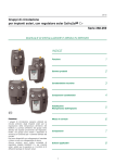
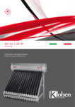
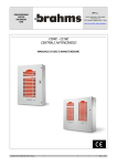
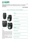
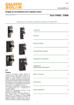
Gamma prodotti
Serie 109 Gruppo di protezione antigelo
1”
AVVERTENZE
Le presenti istruzioni devono essere lette e comprese prima dell’installazione e della manutenzione del
dispositivo.
ATTENZIONE! UNA MANCANZA NEL SEGUIRE QUESTE ISTRUZIONI POTREBBE ORIGINARE PERICOLO!
IL PRODOTTO CON IL QUALE E’ CONFEZIONATO QUESTO FOGLIO ISTRUZIONI E’ DENOMINATO DISPOSITIVO
Il dispositivo deve essere installato, messo in servizio e manutenuto da personale tecnico qualificato in accordo con i
regolamenti nazionali e/o i relativi requisiti locali.
Se il dispositivo non è installato, messo in servizio e manutenuto correttamente secondo le istruzioni contenute in questo manuale, allora può
non funzionare correttamente e porre l’utente in pericolo.
Pulire le tubazioni da eventuali detriti, ruggini, incrostazioni, calcare, scorie di saldatura e da altri contaminanti. Il circuito idraulico deve essere pulito.
Assicurarsi che tutta la raccorderia di collegamento sia a tenuta idraulica.
Nella realizzazione delle connessioni idrauliche, prestare attenzione a non sovrasollecitare meccanicamente le filettature. Nel tempo si possono
produrre rotture con perdite idrauliche a danno di cose e/o persone.
Temperature dell’acqua superiori a 50°C possono provocare gravi ustioni. Durante l’installazione, messa in servizio e manutenzione del
dispositivo, adottare gli accorgimenti necessari affinché tali temperature non arrechino pericolo per le persone.
In caso di acqua molto dura o ricca di impurità, deve esserci predisposizione ad adeguata filtrazione e trattamento dell’acqua prima
dell’ingresso nel dispositivo, secondo la normativa vigente. In caso contrario esso può venire danneggiato e non funzionare correttamente.
Per un funzionamento ottimale, l’aria contenuta nel fluido deve essere rimossa. Per ragioni di sicurezza, a causa dell’alta comprimibilità dell’aria,
sono sconsigliati i test di tenuta sull’intero sistema, e in particolare sulle valvole, tramite aria compressa.
E’ vietato fare un utilizzo diverso del dispositivo rispetto alla sua destinazione d’uso.
L’eventuale abbinamento tra il dispositivo ed altri componenti dell’impianto deve essere effettuato tenendo conto delle caratteristiche di
funzionamento di entrambi. Un eventuale abbinamento non corretto potrebbe pregiudicare il funzionamento del dispositivo e/o dell’impianto.
ATTENZIONE: Rischio di shock elettrico. Parti in tensione. Togliere l’alimentazione elettrica prima di aprire la scatola del dispositivo.
Durante le operazioni di installazione e manutenzione evitare sempre il contatto diretto con parti in tensione o potenzialmente pericolose.
Il dispositivo deve essere installato in un locale appositamente dedicato e non deve essere esposto a gocciolii o umidità, alla luce solare diretta,
alle intemperie, a fonti di calore o campi elettromagnetici di elevata intensità. Tale dispositivo non può essere utilizzato in zone a rischio di
esplosione o incendio.
Il dispositivo deve essere collegato separatamente ad un interruttore bipolare indipendente. In caso fosse necessario l’intervento
sull’apparecchiatura, interrompere prima l’alimentazione elettrica. Non utilizzare dispositivi con riarmo automatico, a tempo o che possono
essere riarmati in modo accidentale.
Utilizzare dispositivi automatici di protezione idonei, in funzione delle caratteristiche elettriche della zona in cui è montato il dispositivo e della
normativa vigente.
Il collegamento a terra deve essere effettuato sempre prima di collegare l’alimentazione. Nel caso fosse necessario rimuovere il dispositivo, il
collegamento a terra deve essere scollegato sempre dopo aver scollegato i conduttori di alimentazione. Verificare che il collegamento a terra
dell’edificio sia realizzato a regola d’arte secondo la normativa vigente.
Il gruppo deve essere installato in un ambiente ove, eventuali perdite di fluido, non arrechino danni a cose e persone
Lasciare il presente manuale ad uso e servizio dell’utente. Smaltire in conformità alla normativa vigente
1
Caratteristiche tecniche
Prestazioni
Materiali
Fluidi d’impiego:
Pressione massima di esercizio:
Pressione massima di prova idraulica:
Campo di temperatura d’esercizio:
Campo di temperatura ambiente:
Valvola differenziale
Corpo valvola e regolatore ∆p:
ottone UNI EN12165 CW617N
Asta di comando e otturatore:
ottone UNI EN12164 CW614N
Guarnizione otturatore, membrana e tenute:
EPDM
Molla:
acciaio inox
Attacchi principali:
acqua
3 bar
5 bar
0÷65°C
-20÷60°C
Valvola sfogo aria
Pressione massima di scarico:
2,5 bar
1” F
Ritegno
Pressione minima di apertura ritegno (Δp):
Valvola sfogo aria
Corpo e coperchio:
Galleggiante:
Asta otturatore:
Molla:
Tenute:
ottone UNI EN12165 CW617N
PP
ottone UNI EN12165 CW617N
acciaio inox
EPDM
Valvola antigelo
Corpo:
Otturatore:
Molle:
Tenute:
Attacchi:
0,01 bar
Valvola antigelo
Temperatura di apertura:
Temperatura di chiusura:
Precisione:
3°C
4°C
±1°C
Centralina elettrica:
Alimentazione elettrica:
Portata massima contatti:
Campo di temperatura ambiente:
Grado di protezione:
ottone UNI EN 12165 CW614N
ottone UNI EN 12165 CW614N
acciaio inox
EPDM
1”M
230 V (ac) - 50/60 Hz
3 (1) A
-20÷60°C
IP 54
Termostato
Temperatura di intervento:
Precisione:
Lunghezza cavo alimentazione:
Raccordo presa di pressione
Corpo:
ottone UNI EN 12164 CW614N
Attacchi:
principali:
1” M
attacco tubo di collegamento: Ø 8 mm
Valvola di ritegno
Corpo:
ottone UNI EN 12165 CW614N
Ritegno:
PPA G40
Molla ritegno:
acciaio inox
Tenuta ritegno:
EP
10°C
±3°C
50 cm
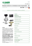
Componenti caratteristici
Il gruppo è composto da:
1) Valvola automatica di sfogo aria.
2) Valvola di ritegno predisposta per valvola di sfogo aria
e termostato di sicurezza, attacchi 1” M.
3) Valvola differenziale, attacchi 1” F.
4) Valvola antigelo, attacchi 1” M.
5) Centralina.
6) Termostato di minima.
7) Raccordo con presa di pressione, attacchi 1” M.
Composizione confezione
La confezione comprende:
- gruppo di protezione antigelo
- foglio istruzioni
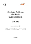
Caratteristiche idrauliche
Gruppo ritegno, termostato, sfogo aria
Valvola differenziale
∆p (kPa)
5000
∆p (kPa)
∆p (mm c.a.)
5000
50
50
4000
40
4000
40
3000
30
3000
30
2000
20
2000
20
11
11
2
10
1
20000
6000
7000
8000
9000
10000
1000
100
100
20000
6000
7000
8000
9000
10000
4000
5000
3000
2000
1000
500
600
700
800
900
400
300
200
100
1
4000
2
5000
200
3000
3
2
200
2000
4
300
500
600
700
800
900
400
3
300
400
4
400
300
9
8
7
6
5
9
8
7
6
5
200
900
800
700
600
500
900
800
700
600
500
100
1000
10
G (l/h)
1000
G (l/h)
∆p (mm c.a.)
Funzionamento
Il gruppo di protezione antigelo ha effetto nel caso di mancanza di tensione elettrica che alimenta l’impianto di riscaldamento e la pompa di
calore. In tali condizioni di malfunzionamento il gruppo provvede al selezionamento dell’impianto in corrispondenza della valvola differenziale
e della valvola di ritegno: quando la temperatura dell’acqua nella tubazione scende al di sotto dei 3°C la valvola antigelo provvede allo scarico
della parte di tubazione esterna.
Installazione
Il gruppo deve essere installato in un impianto con pompa di calore aerotermica. La valvola differenziale con la relativa presa di pressione, il
gruppo con valvola di sfogo aria e termostato devono necessariamente essere installati all’interno dell’edificio, in prossimità della parete oltre
la quale è installata la pompa di calore. La valvola antigelo deve essere installata all’esterno dell’edificio, nel punto più basso del circuito.
Si suggerisce di limitare al massimo le distanze tra gruppo di protezione e la pompa di calore per ridurre al minimo il volume d’acqua da
scaricare nel caso di intervento del sistema.
Valvola automatica
di sfogo aria
ESTERNO
INTERNO
DISCALDIRT®
Valvola
di ritegno
4
3
2
5
1
6
Valvola di scarico
automatica antigelo
Valvola di intercettazione
automatica con intervento in
caso di arresto del circolatore
Gruppo di riempimento
automatico
1) Per il corretto funzionamento del gruppo è necessaria l’installazione di un circolatore (1) esterno alla pompa di calore, a cui abbinare la
valvola differenziale (2) e la presa di pressione (3).
2) Sulla tubazione di ritorno installare a tenuta la valvola differenziale (2) a valle del circolatore, prestando attenzione al senso di flusso
indicato sul corpo valvola (A).
3) La presa di pressione (3) deve essere installata immediatamente a monte del circolatore. Successivamente collegare la valvola differenziale
alla presa di pressione tramite un tubo in rame (Ø = 8 mm).
Svitare la calotta dalla presa della valvola differenziale ed estrarre il cono di tenuta. Inserire calotta e cono di tenuta sul tubo in rame ed
avvitare sulla presa della valvola (D).
4) Sulla tubazione di mandata installare a tenuta il gruppo (4) composto da valvola di ritegno, valvola sfogo aria e sensore di collegamento per
il termostato di minima (4). Prestare attenzione al senso di flusso indicato sul corpo valvola (B).
Per collegare il termostato è sufficiente inserire a pressione il sensore fornito in confezione (C).
5) Installare a tenuta sulla parte esterna di tubazione la valvola antigelo (5) prestando attenzione che sia posizionata nella parte più bassa del
circuito per permettere lo scarico dell’impianto. Per definire il numero e la posizione delle valvole antigelo vedi paragrafo “Prescrizioni per
un corretto posizionamento delle valvole antigelo”.
6) Collegare alla linea il gruppo di riempimento (6) o un accumulo tampone in grado di facilitare il riempimento della parte esterna di
tubazione eventualmente scaricata dall’entrata in funzione del gruppo di protezione.
A
B
D
C
LASCIARE SEMPRE APERTO IL TAPPINO
DELLA VALVOLA SFOGO ARIA.
3
aa
ESTERNO
CALORE
Funzione del termostato e della centralina
Prescrizioni per un corretto posizionamento della valvola
antigelo
Guasto PDC
In caso di guasto della pompa di calore con conseguente assenza
di scambio termico negli scambiatori, il fluido continuerebbe a
circolare nell’impianto e la temperatura si ridurrebbe gradualmente
con il rischio di raffreddare tutto il circuito di riscaldamento.
Quando il termostato diPOMPA
minimaAMBIENTE
rileva una temperatura inferiore ai
DI
ESTERNO
10°C manda un segnale
CALORE alla centralina che toglie corrente al
circolatore bloccando così la circolazione e preservando il circuito
dalle basse temperature.
Funzionamento inverno/estate
Quando la pompa di calore funziona con ciclo di raffrescamento, il
termostato di minima deve essere disinserito per evitare i continui
spegnimenti al raggiungimento dei 10°C.
Esclusione termostato per manutenzione
Se la pompa di calore è rimasta ferma per guasto e la temperatura
dell’impianto è inferiore ai 10°C, al ripristino del funzionamento è
necessario disinserire, tramite il pulsante di colore nero
posizionato sul lato della
scatola elettrica, il termostato di minima
POMPA
DI
CALORE
fino a che la temperatura
dell’impianto non sia tornata superiore ai
10°C.
a
Il dispositivo deve essere installato solo in posizione verticale,
come da schema riportato, in modo tale che l’acqua scaricata
possa fluire correttamente e liberamente verso il basso.
Le valvole antigelo devono essere installate nella parte più fredda
dell’impianto, posizionate lontano da fontiPOMPA
di calore
che possano
AMBIENTE
DI
ESTERNO
CALORE
alterare il corretto funzionamento.
Mantenere una distanza di almeno
15 cm dal terreno al fine di evitare
che la formazione dell’eventuale
colonna di ghiaccio nella zona
sottostante impedisca la fuoriuscita
di acqua dalla valvola.
1) PDC con attacchi alto - basso
Se la pompa di calore presenta gli
attacchi come in figura è sufficiente
una sola valvola antigelo installata
nella tubazione più bassa per
consentire lo svuotamento della
parte esterna di tubazione.
>15 cm
POMPA
DI
CALORE
AMBIENTE
ESTERNO
>15 cm
Collegamenti elettrici
aaa
Con il gruppo antigelo viene fornita la centralina
di regolazione che funge da interfaccia tra il
termostato di minima e il circolatore.
4) Presenza di sifoni
Evitare i collegamenti a sifone.
Se la tubazione di collegamento
presenta una conformazione tale da
creare un effetto sifone (come
riportato in figura), viene impedito lo
scarico di una parte della tubazione
e non è più garantita la protezione
contro il gelo.
>15 cm
POMPA
DI
CALORE
POMPA
DI
CALORE
Spia alimentazione
Forzatura manuale
e raffrescamento
POMPA
DI
POMPACALORE
DI
CALORE
AMBIENTE
ESTERNO
POMPA
DI
CALORE
AMBIENTE
ESTERNO
Comando
di alimentazione
Termostato
di sicurezza
Circolatore
POMPA
DI
CALORE
AMBIENTE
ESTERNO
Manutenzione periodica valvola antigelo
POMPA
DI
CALORE
Svitare il rompivuoto con chiave
fissa esagonale ed estrarlo dal
corpo valvola.
Svitare il tappo dalla calotta,
>15 cm
estrarre l’otturatore
prestando
attenzione alla posizione dei
componenti e pulirlo da eventuali
impurità.
Riassemblare
i
componenti a tenuta ed avvitare il
rompivuoto a battuta sul corpo
valvola.
AMBIENTE
ESTERNO
Installazione consigliata del disaeratore-defangatore.
Si consiglia l’installazione del disaeratore–defangatore
POMPA
AMBIENTE
DI
ESTERNO
DISCALDIRT® per evitare l’accumulo di sporcizia
negli impianti.
CALORE
Tale dispositivo permette di allungare gli intervalli di tempo tra una
manutenzione e la successiva.
Si consiglia di installare il DISCALDIRT® sulla tubazione di
mandata, dopo la valvola di ritegno, così come indicato nello
schema della pagina precedente.
AMBIENTE
ESTERNO
AMBIENTE
ESTERNO
Messa in funzione
Dopo aver collegato tutti i componenti, procedere con il
riempimento dell’impianto per mezzo del gruppo di riempimento.
Potrebbe essere necessario lo spurgo manuale del circolatore per
consentire alla prevalenza della pompa di alzare l’otturatore della
valvola differenziale.
4
ROMPIVUOTO
AMBIENTE
ESTERNO
POMPA
DI
CALORE
TS
POMPA
DI
CALORE
AMBIENTE
ESTERNO
N L
POMPA
DI
CALORE
3) PDC con attacchi in alto
AMBIENTE
ESTERNO
Se la pompa di calore presenta gli
attacchi in alto e le tubazioni sono
posizionate come in figura, sono
necessarie due valvole antigelo per
assicurare lo svuotamento completo
della parte esterna di tubazione.
POMPA
DI
CALORE
1 2 3 4 5 6 7 8 9
2) PDC con attacchi in basso
Se la pompa di calore presenta
entrambi gli attacchi in basso è
necessario installare due valvole
antigelo, una per tubazione. In caso
contrario una tubazione potrebbe
rimanere piena d’acqua con
conseguente rischio di formazione
di ghiaccio.
{
Tappo
Otturatore
Calotta
Corpo
valvola
www.caleffi.com
88166EN
Anti-freeze protection unit
109 series
© Copyright 2013 Calef fi
INSTALLATION AND COMMISSIONING MANUAL
Function
The anti-freeze protection unit is recommended for
unit heater pump systems which only use water as a
medium.
In the event of an electric supply failure or machine
malfunction, external pipes are at risk of frost. The antifreeze unit is a mechanical system which allows the outer
parts of pipes to drain thereby protecting the circuit from
the build up of ice during an electric supply failure and
also protecting the heat pump.
Product range
109 series Anti-freeze protection unit
1”
WARNINGS
These instructions must be read and understood before installing and maintaining the device.
CAUTION! FAILURE TO FOLLOW THESE INSTRUCTIONS COULD RESULT IN A SAFETY HAZARD!
THE PRODUCT SUPPLIED WITH THIS INSTRUCTION SHEET IS REFERRED TO BELOW AS ‘DEVICE’
The device must be installed, commissioned and maintained by qualified technical personnel in accordance with national
regulations and/or relevant local requirements.
If the device is not installed, commissioned and maintained correctly in accordance with the instructions provided in this manual, it may not
function properly and may endanger the user.
Clean the pipes of any debris, rust, incrustations, lime scale, welding slag and any other contaminants. The hydraulic circuit must be clean.
Make sure that all connecting fittings are watertight.
When connecting water pipes, make sure that threaded connections are not overstressed mechanically. Over time this may result in breakage,
causing water damage and/or personal injury.
Water temperatures higher than 50°C may cause severe burns. When installing, commissioning and servicing the device, take the necessary
precautions so that these temperatures will not be hazardous for people.
In the case of particularly hard or impure water, there must be a suitable fitting for filtering and treating the water before it enters the device
inlet, in accordance with current legislation. Otherwise the device may be damaged and will not work properly.
For optimal operation, any air in the medium must be removed. In the interests of safety, due to the high compression capacity of air, testing
the entire system, and especially the valves, for watertightness using compressed air is not recommended.
Any use of the device other than for its intended purpose is prohibited.
Any coupling of the device with other system components must be made while taking the operating principles of both units into consideration.
Incorrect coupling could compromise the operation of the device and/or system.
CAUTION: Risk of electric shock. Live parts. Shut off the electric supply before opening the device box.
During installation and maintenance operations, always avoid direct contact with live or potentially hazardous parts.
The device must be installed in a dedicated location and not exposed to water drops or humidity, direct sunlight, the elements, heat sources
or high intensity electromagnetic fields. This device cannot be used in areas at risk of explosion or fire.
The device must have a separate connection to an independent bipolar switch. If work has to be done on the device, cut off the electric supply
first. Do not use devices with automatic or timed reset, or which may be reset accidentally.
Use suitable automatic protection devices in accordance with the electrical specifications of the zone in which the device is installed and in
compliance with current legislation.
The device must always be earthed before it is connected to the electric supply. If the device has to be removed, always disconnect the earth
connection after disconnecting the electric supply conductors. Check that the earth connection has been made to the highest of standards
under applicable legislation.
The unit must be installed in an environment where any leakage would not cause personal injury or damage to property.
Leave this manual as a reference guide for the user. Dispose of the product in compliance with current legislation
1
Technical specifications
Performance
Materials
Medium:
Maximum working pressure:
Maximum hydraulic test pressure:
Working temperature range:
Ambient temperature range:
Differential pressure regulating valve
Valve body and Dp regulator:
Control stem and obturator:
Obturator seal, diaphragm and seals:
Spring:
brass EN12165 CW617N
brass EN12164 CW614N
EPDM
stainless steel
Main connections:
water
3 bar
5 bar
0–65°C
-20–60°C
Air vent
Max. discharge pressure:
2,5 bar
1” F
Check valve
Check valve minimum opening pressure (Δp):
Air vent
Body and cover:
Float:
Obturator stem:
Spring:
Seals:
brass EN 12165 CW617N
PP
brass EN 12165 CW617N
stainless steel
EPDM
Anti-freeze valve
Body:
Obturator:
Springs:
Seals:
Connections:
brass EN 12165 CW614N
brass EN 12165 CW614N
stainless steel
EPDM
1”M
Pressure port fitting
Body:
Connections:
Check valve
Body:
Check valve:
Check valve spring:
Check valve seal:
0,01 bar
Anti-freeze valve
Opening temperature:
Closing temperature:
Accuracy:
brass EN 12164 CW614N
- main:
1” M
- connecting pipe fitting:
Ø 8 mm
3°C
4°C
±1°C
Electrical control unit:
Electric supply:
Maximum contact rating:
Ambient temperature range:
Protection class:
230 V (ac) - 50/60 Hz
3 (1) A
-20 – 60°C
IP 54
Thermostat
Actuation temperature:
Accuracy:
Electric supply cable length:
10°C
±3°C
50 cm
brass EN 12165 CW614N
PPA G40
stainless steel
EP
Characteristic components
The unit consists of:
1) Automatic air vent.
2) Check valve fitted for an air vent and safety thermostat, 1” M
connections.
3) Differential pressure regulating valve, 1” F connections.
4) Anti-freeze valve, 1” M connections.
5) Control unit.
6 Minimum temperature thermostat.
7) Fitting with pressure point, 1” M connections.
Package contents
The package contains:
- Anti-freeze protection unit
- Instruction sheet
Hydraulic characteristics
Check valve, thermostat, air vent assembly
Differential pressure regulating valve
Δp (kPa)
50
5000
50
5000
Δp (kPa)
Δp (mm w.g.)
4000
40
4000
40
3000
30
3000
30
2000
20
2000
20
11
11
2
10
1
20,000
6000
7000
8000
9000
10,000
1000
100
100
20,000
6000
7000
8000
9000
10,000
4000
5000
3000
2000
1000
500
600
700
800
900
400
300
200
100
1
4000
2
5000
200
3000
2
200
2000
3
500
600
700
800
900
4
300
400
400
3
300
300
4
400
200
9
8
7
6
5
9
8
7
6
5
100
1000
10
900
800
700
600
500
900
800
700
600
500
G (l/h)
1000
G (l/h)
Δp (mm w.g.)
Operating principle
The anti-freeze protection unit only works when the electric supply to the heating system and heat pump fails. In the event of this kind of
malfunction, the unit closes the part of the system between the differential pressure regulating valve and the check valve: when the temperature
of the water in the pipes falls below 3°C, the anti-freeze valve drains the external part of the pipe.
Installation
The unit must be installed in a unit heater pump system. The differential valve and associated pressure port, and the unit with air vent and
thermostat must always be installed inside the building close to the wall, on the other side of which the heat pump is installed. The anti-freeze
valve must be installed outside the building at the lowest point in the circuit.
We recommend limiting as much as possible the distance between the anti-freeze protection unit and the heat pump to keep the amount of
water to be drained to a minimum, should the anti-freeze system be required.
Automatic air vent
OUTSIDE
Check valve
INSIDE
DISCALDIRT®
4
3
2
5
1
6
Anti-freeze
automatic drain valve
Automatic shut-off valve
with intervention in case
of circulator stop
Automatic filling unit
1) A circulator (1) (with associated differential pressure regulating valve (2) and pressure port (3)) must be installed externally to the heat pump
to assure the correct operation of the unit.
2) Install the differential pressure regulating valve (2) on the return pipe downstream of the circulator, bearing in mind the direction of flow
indicated on the valve body (A).
3) The pressure port (3) must be installed immediately upstream of the circulator. After this, use a copper pipe (Ø = 8 mm) to connect the
differential pressure regulating valve to the pressure port.
Unscrew the nut from the port on the differential pressure regulating valve and pull out the sealing cone. Apply the nut and sealing cone
onto the copper pipe and screw onto the valve inlet (D).
4) Install on the flow pipe the assembly (4) including the check valve, air vent and connection sensor for the minimum temperature thermostat
(4). Check the direction of flow indicated on the valve body (B).
To connect the thermostat, just press in the sensor supplied in the package (C).
5) Install the anti-freeze valve (5) on the outer part of the pipe, making sure it is positioned on the lowest part of the circuit to allow the system
to empty fully. See the section entitled “How to position anti-freeze valves” for information on how many and where to install anti-freeze
valves.
6) Connect the filling unit (6) to the line, or alternatively a buffer tank that can help fill the outer part of the pipe emptied when the frost protection
unit goes into action.
ALWAYS LEAVE THE AIR VENT VALVE CAP
3
CALORE
Indications on the correct positioning of the anti-freeze
valve
Thermostat and control unit function
Heat pump failure
If the heat pump fails and there is no heat exchange in the heat
exchangers, the medium would continue to flow in the system and
the temperature would gradually drop, with the risk of cooling the
entire heating circuit.
When the minimum temperature thermostat measures a
HEAT
OUTDOOR
temperature of less than
PUMP10°C, it sends a signal to the control unit
ENVIRONMENT
which cuts off electric supply to the circulator, stops circulation and
protects the circuit from low temperatures.
Winter/summer operation
When the heat pump functions with the cooling cycle, the minimum
temperature thermostat must be disabled to prevent continuous
switching on and off every time 10°C is reached.
By-passing the thermostat for maintenance
If the heat pump stops due to a malfunction and the system
temperature drops below 10°C, when function is restored, use the
black button on the side of the wiring box to disable the minimum
temperature thermostat until theO system temperature rises back
above 10°C.
The device must only be installed vertically, as shown in the
diagram, to allow water to drain properly and free from obstruction.
Anti-freeze valves must be installed in the coldest part of the
system, away from any heat sources which could impair function.
HEAT
PUMP
1) Heat pump with connections at
the top-bottom
If the heat pump has connections as
illustrated, just one anti-freeze valve
is enough on the lowest pipe to
make sure the outer part empties
properly.
4) Presence of syphons
Do not make any syphons
connections.
If the shape of the connection pipe
has the potential to create a syphon
effect (as illustrated), part of the
pipe will not be able to drain and
frost protection will no longer be
guaranteed.
HEAT
PUMP
OUTDOOR
ENVIRONMENT
Wiring diagrams
A regulation unit is supplied along with the antifreeze protection unit, to provide an interface
between the minimum temperature thermostat
and circulator.
HEAT
PUMP
HEAT
PUMP
OUTDOOR
ENVIRONMENT
Electric supply
indicator lamp
Manual force and
cooling
HEAT
PUMP
HEAT
PUMP
Electric supply
command
Safety
thermostat
Circulator
HEAT
PUMP
OUTDOOR
ENVIRONMENT
OUTDOOR
ENVIRONMENT
Regular anti-freeze valve maintenance
HEAT
PUMP
Unscrew the vacuum breaker
using a hexagonal wrench and
pull it out of the valve body.
Take the plug off the nut, pull out
cm
the obturator >15(checking
the
position of components) and
remove
any
impurities.
Reassemble the components and
fully screw the vacuum breaker
back onto the valve body.
OUTDOOR
ENVIRONMENT
>15 cm
HEAT
PUMP
OUTDOOR
ENVIRONMENT
ST
3) Heat pump with connections at
the top
If the heat pump has the
connections at the top and the pipes
are positioned as illustrated, two
anti-freeze valves are needed to
make sure the outer part of the pipe
empties properly.
OUTDOOR
ENVIRONMENT
OUTDOOR
ENVIRONMENT
N L
HEAT
PUMP
HEAT
PUMP
1 2 3 4 5 6 7 8 9
2) Heat pump with connections at
the bottom
If the heat pump has both
connections at the bottom, two antifreeze valves must be installed, one
for each pipe. Otherwise, water may
be left in one pipe which could then
freeze.
>15 cm
Recommended installation of deaerator-dirt separator.
®
We
recommend installing the DISCALDIRT
deaerator-dirt
HEAT
OUTDOOR
OUTDOOR
PUMP
ENVIRONMENT
separator to prevent dirt from building up in systems. ENVIRONMENT
This device means maintenance will be required less frequently.
DISCALDIRT® should be installed on flow pipes after the check
valve, as shown in the diagram overleaf.
Commissioning
Once all components have been connected, fill the system using
the filling unit.
The circulator may need to be manually deaerated to allow the
pump head to raise the differential valve obturator.
OUTDOOR
ENVIRONMENT
4
VACUUM BREAKER
Leave at least 15 cm clearance from
the ground to prevent the block of
ice which may form below from
stopping water from draining from
the valve.
OUTDOOR
ENVIRONMENT
Plug
{
Obturator
Nut
Valve
body
>15 cm