1
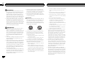
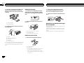
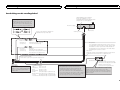
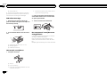
English DVD RDS RECEIVER AUTORADIO DVD RDS SINTO LETTORE DVD CON RDS RADIO RDS CON DVD DVD-RDS-EMPFÄNGER DVD RDS-ONTVANGER Français Español Deutsch Installation Manual Manuel d’installation Manuale d’installazione Manual de instalación Installationsanleitung Installatiehandleiding Italiano DVH-340UB Nederlands Section 01 Connections ! Do not shorten any cables. If you do, the protection circuit may fail to work properly. CAUTION 2 En O STAR ACC position ! PIONEER does not recommend that you install or service your display unit yourself. Installing or servicing the product may expose you to risk of electric shock or other hazards. Refer all installation and servicing of your display unit to authorized Pioneer service personnel. ! Secure all wiring with cable clamps or electrical tape. Do not allow any bare wiring to remain exposed. ! Do not drill a hole into the engine compartment to connect the yellow cable of the display unit to the vehicle battery. Engine vibration may eventually cause the insulation to fail at the point where the wire passes from the passenger compartment into the engine compartment. Take extra care in securing the wire at this point. ! It is extremely dangerous to allow the display lead to become wound around the steering column or shift lever. Be sure to install the display in such a way that it will not obstruct driving. ! Make sure that wires will not interfere with moving parts of the vehicle, such as the shift lever, parking brake or seat sliding mechanism. F N OF Important ! When installing this unit in a vehicle without an ACC (accessory) position on the ignition switch, failure to connect the red cable to the terminal that detects operation of the ignition key may result in battery drain. T WARNING ! To avoid the risk of accident and the potential violation of applicable laws, no viewing of front seat video should ever occur while the vehicle is being driven. Also, rear displays should not be in a location where they are visibly distracting to the driver. ! In some countries or states the viewing of images on a display inside a vehicle even by persons other than the driver may be illegal. Where such regulations apply, they must be obeyed and this unit’s DVD features should not be used. Connections No ACC position ! Use of this unit in conditions other than the following could result in fire or malfunction. — Vehicles with a 12-volt battery and negative grounding. — Speakers with 50 W (output value) and 4 W to 8 W (impedance value). ! To prevent a short-circuit, overheating or malfunction, be sure to follow the directions below. — Disconnect the negative terminal of the battery before installation. — Secure the wiring with cable clamps or adhesive tape. Wrap adhesive tape around wiring that comes into contact with metal parts to protect the wiring. — Place all cables away from moving parts, such as the shift lever and seat rails. — Place all cables away from hot places, such as near the heater outlet. — Do not connect the yellow cable to the battery by passing it through the hole to the engine compartment. — Cover any disconnected cable connectors with insulating tape. — Do not shorten any cables. — Never cut the insulation of the power cable of this unit in order to share the power with other devices. The current capacity of the cable is limited. — Use a fuse of the rating prescribed. — Never wire the negative speaker cable directly to ground. — Never band together negative cables of multiple speakers. ! When this unit is on, control signals are sent through the blue/white cable. Connect this cable to the system remote control of an external power amp or the vehicle’s auto-antenna relay control terminal (max. 300 mA 12 V DC). If the vehicle is equipped with a glass antenna, connect it to the antenna booster power supply terminal. ! Never connect the blue/white cable to the power terminal of an external power amp. Also, never connect it to the power terminal of the auto antenna. Doing so may result in battery drain or a malfunction. ! The black cable is ground. Ground cables for this unit and other equipment (especially, high-current products such as power amps) must be wired separately. If they are not, an accidental detachment may result in a fire or malfunction. Section Connections 01 Connections Power cable connection 2* 1* 4* 3* English Wired remote input Hard-wired remote control adapter can be connected (sold separately). Note: Depending on the kind of vehicle, the function of 2* and 4* may be different. In this case, be sure to connect 1* to 4* and 3* to 2*. Antenna jack Connect leads of the same color to each other. Yellow (2*) Back-up (or accessory) Yellow (1*) Connect to the constant 12 V supply terminal. Red (4*) Accessory (or back-up) Red (3*) Connect to terminal controlled by ignition switch (12 V DC). Fuse (10 A) This product Yellow/black If you use an equipment with Mute function, wire this lead to the Audio Mute lead on that equipment. If not, keep the Audio Mute lead free of any connections. Blue/white Connect to system control terminal of the power amp (max. 300 mA 12 V DC). Black (chassis ground) Connect to a clean, paint-free metal location. Blue/white (5*) ISO connector Note: In some vehicles, the ISO connector may be divided into two. In this case, be sure to connect to both connectors. Speaker leads White: Front left White/black: Front left Gray: Front right Gray/black: Front right Green: Rear left or subwoofer Green/black: Rear left or subwoofer Violet: Rear right or subwoofer Violet/black: Rear right or subwoofer Notes: Change the initial setting of this unit (refer to the Operation Manual). The subwoofer output of this unit is monaural. When using a subwoofer of 70 W (2 Ω), be sure to connect the subwoofer to the violet and violet/black leads of this unit. Do not connect anything to the green and green/black leads. Blue/white (6*) Connect to auto-antenna relay control terminal (max. 300 mA 12 V DC). The pin position of the ISO connector will differ depends on the type of vehicle. Connect 5* and 6* when Pin 5 is an antenna control type. In another type of vehicle, never connect 5* and 6*. En 3 Section 01 Connections Connections When connecting to separately sold power amp Connect with RCA cables (sold separately) Power amp (sold separately) Power amp (sold separately) Front output Rear output or subwoofer output This product Blue/white Connect to system control terminal of the power amp (max. 300 mA 12 V DC). System remote control Blue/white (5*) The pin position of the ISO connector will differ depends on the type of vehicle. Connect 5* and 6* when Pin 5 is an antenna control type. In another type of vehicle, never connect 5* and 6*. Blue/white (6*) Connect to auto-antenna relay control terminal (max. 300 mA 12 V DC). Left Front speaker Rear speaker or subwoofer Right Front speaker Rear speaker or subwoofer Perform these connections when using the optional amplifier. 4 En Section Connections 01 Installation 02 WARNING Never install the display in a location where it is visible to the driver while driving. When connecting the external video component It is necessary to set V.INPUT to AUX in initial settings when connecting the external video component. External video component (sold separately) Display with RCA input jacks To video input To audio output RCA cable (sold separately) RCA cable (sold separately) To video output RCA cable (sold separately) ! ! ! — it may interfere with operation of the vehicle. — it may cause injury to a passenger as a result of a sudden stop. ! The semiconductor laser will be damaged if it overheats. Install this unit away from hot places such as near the heater outlet. ! Optimum performance is obtained when the unit is installed at an angle of less than 30°. Use commercially available parts when installing. DIN Front-mount 1 Insert the mounting sleeve into the dashboard. For installation in shallow spaces, use the supplied mounting sleeve. If there is enough space, use the mounting sleeve that came with the vehicle. 2 Secure the mounting sleeve by using a screwdriver to bend the metal tabs (90°) into place. 1 Video input (VIDEO INPUT) Video output (VIDEO OUTPUT) 15 cm This product This product ! Important Check all connections and systems before final installation. Do not use unauthorized parts as this may cause malfunctions. Consult your dealer if installation requires drilling of holes or other modifications to the vehicle. Do not install this unit where: English When using a display connected to video outputs 2 ! When installing, to ensure proper heat dispersal when using this unit, make sure you leave ample space behind the rear panel and wrap any loose cables so they are not blocking the vents. 1 Dashboard 2 Mounting sleeve 3 Install the unit as illustrated. 1 15 cm Audio input 4 Leave ample 5 cm space 5 cm 2 3 5 5cm cm DIN front/rear mount 1 2 3 4 5 Nut Firewall or metal support Metal strap Screw Screw (M4 × 8) This unit can be properly installed using either front-mount or rear-mount installation. En 5 Section 02 Installation # Make sure that the unit is installed securely in place. An unstable installation may cause skipping or other malfunctions. 2 Insert the supplied extraction keys into both sides of the unit until they click into place. DIN Rear-mount 3 Pull the unit out of the dashboard. 1 Determine the appropriate position where the holes on the bracket and the side of the unit match. 2 Tighten two screws on each side. 3 1 2 1 Tapping screw (5 mm × 8 mm) 2 Mounting bracket 3 Dashboard or console Removing the unit 1 Remove the trim ring. 1 Trim ring 2 Notched tab ! Releasing the front panel allows easier access to the trim ring. ! When reattaching the trim ring, point the side with the notched tab down. 6 En Removing and re-attaching the front panel You can remove the front panel to protect your unit from theft. Press the detach button and push the front panel upward and pull it toward you. For details, refer to operation manual. English 7 En Section 01 Connexions ! Assurez-vous que les fils n’interfèrent pas avec des parties mobiles du véhicule, telles que le levier de vitesse, le frein de parking ou le mécanisme de glissement des sièges. ! Ne raccourcissez pas les câbles. Cela pourrait empêcher le fonctionnement adéquat du circuit de protection. Important ! Lors de l’installation de cet appareil dans un véhicule sans position ACC (accessoire) sur le contact d’allumage, ne pas connecter le câble rouge à la borne qui détecte l’utilisation de la clé de contact peut entraîner le déchargement de la batterie. 8 Fr O T ! PIONEER ne recommande pas que vous installiez ou entreteniez votre écran vous même. L’installation ou l’entretien du produit peut vous exposer à des risques d’électrocution ou à d’autres dangers. Adressez-vous à du personnel d’entretien agréé par Pioneer pour l’installation et l’entretien de votre écran. ! Fixez tout le câblage avec des serre-fils ou de la bande électrique. Ne laissez aucun câblage nu exposé. ! Ne percez pas de trous vers le compartiment moteur pour connecter le câble jaune de l’écran à la batterie du véhicule. Les vibrations du moteur peuvent provoquer un défaut d’isolement à l’endroit où le fil passe du compartiment passager au compartiment moteur. Apportez une attention particulière à la fixation du fil à cet endroit. ! Il est extrêmement dangereux de laisser le fil de l’écran s’enrouler autour de la colonne de direction ou du levier de vitesse. Assurezvous d’installer l’écran de telle manière qu’il ne gêne pas la conduite. F Avec position ACC STAR PRÉCAUTION N OF ATTENTION ! Pour éviter le risque d’accident et une violation potentielle des lois applicables, l’écran du siège avant ne doit en aucun cas être regardé pendant la conduite du véhicule. En outre, les écrans arrière ne doivent pas être placés dans un endroit où ils constituent visiblement une distraction pour le conducteur. ! Dans certains états ou pays, il peut être illégal même pour des personnes autres que le conducteur de regarder des images sur un écran à l’intérieur d’un véhicule. Quand cette réglementation est applicable, elle doit être respectée, et les fonctions DVD de cet appareil ne doivent pas être utilisées. Connexions Sans position ACC ! L’utilisation de cet appareil dans des conditions autres que les conditions suivantes pourrait provoquer un incendie ou un mauvais fonctionnement. — Véhicules avec une batterie 12 volts et mise à la masse du négatif. — Haut-parleurs avec une puissance de sortie de 50 W et une impédance de 4 W à 8 W. ! Pour éviter un court-circuit, une surchauffe ou un dysfonctionnement, assurez-vous de respecter les instructions suivantes. — Déconnectez la borne négative de la batterie avant l’installation. — Fixez le câblage avec des serre-fils ou de la bande adhésive. Pour protéger le câblage, enroulez dans du ruban adhésif les parties du câblage en contact avec des pièces en métal. — Placez les câbles à l’écart de toutes les parties mobiles, telles que le levier de vitesse et les rails des sièges. — Placez les câbles à l’écart de tous les endroits chauds, par exemple les sorties de chauffage. — Ne reliez pas le câble jaune à la batterie à travers le trou dans le compartiment moteur. — Recouvrez tous les connecteurs de câbles qui ne sont pas connectés avec du ruban adhésif isolant. — Ne raccourcissez pas les câbles. — Ne coupez jamais l’isolation du câble d’alimentation de cet appareil pour partager l’alimentation avec d’autres appareils. La capacité en courant du câble est limitée. — Utilisez un fusible correspondant aux caractéristiques spécifiées. — Ne câblez jamais le câble négatif du haut-parleur directement à la masse. — Ne réunissez jamais ensemble les câbles négatifs de plusieurs haut-parleurs. ! Lorsque cet appareil est sous tension, les signaux de commande sont transmis via le câble bleu/blanc. Connectez ce câble à la télécommande du système d’un amplificateur de puissance externe ou à la borne de commande du relais de l’antenne motorisée du véhicule (max. 300 mA 12 V CC). Si le véhicule est équipé d’une antenne intégrée à la lunette arrière, connectez-le à la borne d’alimentation de l’amplificateur d’antenne. ! Ne reliez jamais le câble bleu/blanc à la borne d’alimentation d’un amplificateur de puissance externe. De même, ne le reliez pas à la borne d’alimentation de l’antenne motorisée. Dans le cas contraire, il peut en résulter un déchargement de la batterie ou un dysfonctionnement. ! Le câble noir est la masse. Les câbles de terre de cet appareil et d’autres produits (particulièrement les produits avec des courants élevés tels que l’amplificateur de puissance) doivent être câblés séparément. Dans le cas contraire, ils peuvent se détacher accidentellement et provoquer un incendie ou un dysfonctionnement. Section Connexions 01 Connexions Connexion du câble d’alimentation Entrée pour télécommande câblée Un adaptateur de télécommande câblée peut être connecté à cette prise (vendu séparément). 2* 1* 4* 3* Français Remarque: En fonction du type de véhicule, la fonction de 2* et de 4* peut différer. Dans ce cas, assurez-vous de connecter 1* à 4* et 3* à 2*. Entrée d’antenne Connectez les câbles de la même couleur les uns aux autres. Jaune (2*) Secours (ou accessoire) Jaune (1*) Connectez à une prise d’alimentation constante 12 V. Rouge (4*) Accessoire (ou secours) Rouge (3*) Connectez à une prise commandée par le commutateur d’allumage (12 V CC). Cet appareil Fusible (10 A) Jaune/noir Si vous utilisez un équipement avec une fonction de mise en sourdine, raccordez ce conducteur au conducteur de mise en sourdine audio de cet équipement. Sinon, laissez le conducteur de mise en sourdine audio non raccordé. Bleu/blanc Connectez à la prise de commande du système de l’amplificateur de puissance (max. 300 mA 12 V CC). Noire (masse au châssis) Connectez à une section métallique propre et sans peinture. Bleu/blanc (5*) Connecteur ISO Remarque: Dans certains véhicules, le connecteur ISO peut être divisé en deux. Dans ce cas, assurez-vous de faire la connexion aux deux connecteurs. Câbles d’enceinte Blanc: Avant gauche Blanc/noir: Avant gauche Gris: Avant droit Gris/noir: Avant droit Vert: Arrière gauche ou haut-parleur d’extrêmes graves Vert/noir: Arrière gauche ou haut-parleur d’extrêmes graves Violet: Arrière droite ou haut-parleur d’extrêmes graves Violet/noir: Arrière droite ou haut-parleur d’extrêmes graves Remarques: Changez les réglages initiaux de cet appareil (reportez-vous au mode d’emploi). La sortie haut-parleur d’extrêmes graves de cet appareil est monaurale. Lors de l’utilisation d’un haut-parleur d’extrêmes graves de 70 W (2 ǡ), assurez-vous de connecter le haut-parleur d’extrêmes graves aux fils violet et violet/noir de cet appareil. Ne connectez aucun périphérique aux fils vert et vert/noir. Bleu/blanc (6*) Connectez à la prise du contrôle de relais de l’antenne automatique (max. 300 mA, 12 V CC). La position des broches du connecteur ISO diffère en fonction du type de véhicule. Connectez 5* et 6* quand la broche 5 correspond à la commande de l’antenne. Dans les autres cas, ne connectez jamais 5* et 6*. Fr 9 Section 01 Connexions Connexions Lors de la connexion à un amplificateur de puissance vendu séparément Raccordez avec des câbles cinch (RCA) (vendus séparément) Amplificateur de puissance (vendu séparément) Amplificateur de puissance (vendu séparément) Cet appareil Sortie avant Sortie arrière ou haut-parleur d’extrêmes graves Bleu/blanc Connectez à la prise de commande du système de l’amplificateur de puissance (max. 300 mA 12 V CC). Télécommande du système Bleu/blanc (5*) La position des broches du connecteur ISO diffère en fonction du type de véhicule. Connectez 5* et 6* quand la broche 5 correspond à la commande de l’antenne. Dans les autres cas, ne connectez jamais 5* et 6*. Bleu/blanc (6*) Connectez à la prise du contrôle de relais de l’antenne automatique (max. 300 mA, 12 V CC). Gauche Haut-parleur avant Haut-parleur arrière ou haut-parleur d’extrêmes graves Droit Haut-parleur avant Haut-parleur arrière ou haut-parleur d’extrêmes graves Réalisez ces connexions lors de l’utilisation de l’amplificateur en option. 10 Fr Section Connexions 01 Installation 02 Lors de l’utilisation d’un écran connecté à la sortie vidéo ATTENTION N’installez jamais d’écran dans un endroit où il est visible du conducteur. Il est nécessaire de régler V.INPUT sur AUX dans les réglages initiaux lors de la connexion du composant vidéo externe. Appareil vidéo externe (vendu séparément) À l’entrée vidéo Aux sorties audio Câble Cinch (vendu séparément) Câble Cinch (vendu séparément) À la sortie vidéo Câble Cinch (vendu séparément) ! ! ! ! Important Vérifiez toutes les connexions et tous les systèmes avant l’installation finale. N’utilisez pas de pièces non autorisées car il peut en résulter des dysfonctionnements. Consultez votre revendeur si l’installation nécessite le perçage de trous ou d’autres modifications du véhicule. N’installez pas cet appareil là où : — il peut interférer avec l’utilisation du véhicule. — il peut blesser un passager en cas d’arrêt soudain du véhicule. ! Le laser à semi-conducteur sera endommagé s’il devient trop chaud. Installez cet appareil à l’écart de tous les endroits chauds, par exemple les sorties de chauffage. ! Des performances optimales sont obtenues quand l’appareil est installé à un angle inférieur à 30°. Montage avant/arrière DIN Cet appareil peut être installé correctement soit en montage frontal ou en montage arrière. Utilisez des pièces disponibles dans le commerce lors de l’installation. Montage frontal DIN 1 Insérez le manchon de montage dans le tableau de bord. Lors de l’installation de cet appareil dans un espace peu profond, utilisez le manchon de montage fourni. Si l’espace est suffisant, utilisez le manchon de montage fourni avec le véhicule. 2 Fixez le manchon de montage en utilisant un tournevis pour courber les pattes métalliques (90°) en place. 1 Entrée vidéo (VIDEO INPUT) Sortie vidéo (VIDEO OUTPUT) 15 cm Cet appareil Cet appareil Français Affichage avec prises d’entrée Cinch Lors de la connexion du composant vidéo externe 15 cm Entrée audio 2 ! Lors de l’installation, pour assurer une dispersion correcte de la chaleur quand cet appareil est utilisé, assurez-vous de laisser un espace important derrière la face arrière et enroulez les câbles volants de façon qu’ils ne bloquent pas les orifices d’aération. 1 Tableau de bord 2 Manchon de montage 3 Installez l’appareil comme indiqué sur la figure. 1 Laissez suffisamment 5 cm d’espace 5 cm 4 5cm cm 2 3 5 1 Écrou 2 Pare-feu ou support métallique 3 Attache en métal Fr 11 Section 02 Installation 4 Vis 5 Vis (M4 × 8) # Assurez-vous que l’appareil est correctement mis en place. Toute installation instable peut entraîner des sauts ou autres dysfonctionnements. ! Quand vous remontez l’anneau de garniture, pointez le côté avec l’encoche vers le bas. 2 Insérez les clés d’extraction fournies dans les deux côtés de l’appareil jusqu’à ce qu’elles s’enclenchent en place. Montage arrière DIN 1 Déterminez la position appropriée où les trous sur le support et sur le côté de l’appareil se correspondent. 2 Serrez deux vis de chaque côté. 3 1 2 1 Vis taraudeuse (5 mm × 8 mm) 2 Support de montage 3 Tableau de bord ou console Retrait de l’appareil 1 Retirez l’anneau de garniture. 1 Anneau de garniture 2 Encoche ! Retirer la face avant permet d’accéder plus facilement à l’anneau de garniture. 12 Fr 3 Tirez l’appareil hors du tableau de bord. Retrait et remontage de la face avant Vous pouvez retirer la face avant pour protéger l’appareil contre le vol. Appuyez sur la touche de retrait, puis poussez la face avant vers le haut et tirez-la vers vous. Pour plus de détails, reportez-vous au mode d’emploi. Français 13 Fr Sezione 01 Collegamenti ! Assicurarsi che i cavi non interferiscano con le parti mobili del veicolo, come la leva del cambio, il freno a mano o il meccanismo di scorrimento dei sedili. ! Non accorciare i cavi. In caso contrario, il circuito di protezione potrebbe non funzionare correttamente. Importante ! Quando si installa questa unità in un veicolo che non dispone della posizione ACC (accessoria) per l’interruttore della chiave di avviamento, se non si collega il cavo rosso a un terminale accoppiato al funzionamento dell’interruttore della chiave di avviamento, la batteria potrebbe scaricarsi. 14 It O T ! PIONEER non raccomanda di installare o effettuare interventi di manutenzione sull’unità display da soli. L’installazione o la manutenzione del prodotto può esporre al rischio di scosse elettriche o altri pericoli. Per tutti gli interventi di installazione e manutenzione dell’unità display rivolgersi a personale tecnico autorizzato Pioneer. ! Assicurare tutti i cavi con morsetti per cavi o nastro isolante. Non lasciare cavi scoperti esposti. ! Non trapanare un foro nel comparto motore per collegare il cavo giallo dell’unità display alla batteria del veicolo. Le vibrazioni del motore possono a lungo andare danneggiare l’isolante nel punto dove il cavo passa dall’abitacolo al comparto motore. Fare particolare attenzione quando si fissa il cavo in questo punto. ! È estremamente pericoloso se il filo di sostegno del display si avvolge attorno al piantone dello sterzo o alla leva del cambio. Accertarsi quindi di installare il display in modo tale da non ostacolare la guida. F Con posizione ACC STAR ATTENZIONE N OF AVVERTENZA ! Per evitare il rischio di incidenti e la potenziale violazione delle normative in vigore, la visione dei video dal sedile anteriore è vietata mentre il veicolo è in movimento. Inoltre, i display posteriori non devono trovarsi in posizioni che possano rappresentare una distrazione visiva per il conducente. ! In alcuni Stati o Paesi la visione di immagini su un display installato all’interno di un veicolo, anche da parte di persone diverse dal conducente, potrebbe essere illegale. Se sono in vigore norme di questo tipo, è necessario osservarle scrupolosamente e le caratteristiche DVD di questa unità non devono essere utilizzate. Collegamenti Senza posizione ACC ! Se questa unità viene utilizzata in condizioni diverse dalle seguenti, potrebbero verificarsi incendi o malfunzionamenti. — Veicoli dotati di batteria da 12 volt e messa a terra negativa. — Altoparlanti con uscita nominale da 50 W e impedenza nominale compresa tra 4 W e 8 W. ! Per evitare rischi di cortocircuito, surriscaldamento o malfunzionamento, accertarsi di seguire le indicazioni riportate di seguito. — Prima dell’installazione, scollegare il morsetto negativo della batteria. — Assicurare i cavi con morsetti per cavi o nastro adesivo. Per proteggere i cavi, avvolgere nastro adesivo attorno agli stessi nei punti in cui entrano in contatto con parti metalliche. — Posizionare tutti i cavi in modo che non possano entrare in contatto con componenti mobili, come la leva del cambio e i binari dei sedili. — Non posizionare i cavi in luoghi soggetti a surriscaldamento, come le bocchette dell’impianto di riscaldamento. — Non collegare il cavo giallo alla batteria facendolo passare attraverso fori nel vano motore. — Rivestire tutti i connettori scollegati con nastro isolante. — Non accorciare i cavi. — Non condividere mai l’alimentazione con altri dispositivi tagliando l’isolante del cavo di alimentazione dell’unità. La capacità di carico di corrente del cavo è limitata. — Utilizzare esclusivamente un fusibile con la portata prescritta. — Non collegare mai direttamente a terra il cavo negativo dell’altoparlante. — Non legare mai assieme cavi negativi di più altoparlanti. ! Quando questa unità è accesa, i segnali di controllo vengono trasmessi dal cavo blu/ bianco. Collegare questo cavo al telecomando di sistema di un amplificatore di potenza esterno o al terminale di controllo del relè dell’antenna automatica del veicolo (max. 300 mA 12 V CC). Se il veicolo è dotato di un’antenna a vetro, collegarla al terminale di alimentazione di potenza dell’antenna. ! Non collegare mai il cavo blu/bianco al terminale di alimentazione dell’amplificatore di potenza esterno. Inoltre, non collegarlo mai al terminale di alimentazione dell’antenna automatica. In caso contrario, la batteria potrebbe scaricarsi o potrebbero verificarsi malfunzionamenti. ! Il cavo nero è la messa a terra. I cavi di messa a terra per questa unità e per le altre apparecchiature (soprattutto per i prodotti ad alta tensione, quali l’amplificatore di potenza) devono essere collegati separatamente. In caso contrario, se scollegati accidentalmente, potrebbero provocare incendi o malfunzionamenti. Sezione Collegamenti 01 Collegamenti Collegamento del cavo di alimentazione Ingresso per telecomando a filo Qui si collega mediante cavo l’adattatore per telecomando (venduto a parte). Nota: A seconda del tipo di veicolo la funzione di 2* e di 4* potrebbe differire. In tal caso collegare 1* a 4* e 3* a 2*. Ingresso antenna 1* 4* 3* Collegare fra loro i cavi di uguale colore. Giallo (2*) Retromarcia (o accessori) Giallo (1*) Da collegare al terminale costantemente alimentato a 12 V. Rosso (4*) Accessori (o retromarcia) Rosso (3*) Da collegare al terminale controllato dalla chiave di accensione (12 V CC). Fusibile (10 A) Questo apparecchio Italiano 2* Giallo/nero In caso d’uso di un apparecchio provvisto della funzione di silenziamento, questo cavo deve essere collegato al corrispondente cavo di silenziamento audio dell’apparecchio stesso. In caso contrario non lo si deve collegare. Blu/bianco Da collegare al terminale di controllo di sistema dell’amplificatore di potenza (massimo 300 mA 12 V CC). Nero (messa a terra sulla carrozzeria) Da collegare in un punto metallico non verniciato. Blu/bianco (5*) Connettore ISO Nota: In alcuni veicoli il connettore ISO potrebbe essere separato in due. In tal caso è necessario collegare entrambi. Cavi altoparlanti Bianco: anteriore sinistro Bianco/nero: anteriore sinistro Grigio: anteriore destro Grigio/nero: anteriore destro Verde: posteriore sinistro o subwoofer Verde/nero: posteriore sinistro o subwoofer Viola: posteriore destro o subwoofer Viola/nero: posteriore destro o subwoofer Note: Cambiare le impostazioni iniziali dell’unità (vedere il manuale d’istruzioni). L’uscita subwoofer di questa unità è mono. Se si usa un subwoofer da 70 W (2 Ω), collegarlo ai fili viola e viola/nero di questa unità. Non collegare nulla ai fili verde e verde/nero. Blu/bianco (6*) Da collegare al terminale di controllo del relè dell’antenna automatica (massimo 300 mA 12 V CC). La posizione dei contatti del connettore ISO può differire in funzione del tipo di veicolo. Collegare 5* e 6* qualora il contatto 5 sia del tipo per controllo dell’antenna. In altri tipi di veicolo 5* e 6* non devo mai essere collegati. It 15 Sezione 01 Collegamenti Collegamenti Quando l’unità viene collegata a un amplificatore di potenza venduto a parte Collegare con cavi RCA (venduti a parte) Amplificatore di potenza (venduto a parte) Amplificatore di potenza (venduto a parte) Uscita anteriore Uscita posteriore o del subwoofer Questo apparecchio Blu/bianco Da collegare al terminale di controllo di sistema dell’amplificatore di potenza (massimo 300 mA 12 V CC). Telecomando del sistema Blu/bianco (5*) La posizione dei contatti del connettore ISO può differire in funzione del tipo di veicolo. Collegare 5* e 6* qualora il contatto 5 sia del tipo per controllo dell’antenna. In altri tipi di veicolo 5* e 6* non devo mai essere collegati. Blu/bianco (6*) Da collegare al terminale di controllo del relè dell’antenna automatica (massimo 300 mA 12 V CC). Sinistra Altoparlante anteriore Altoparlante posteriore o subwoofer Destra Altoparlante anteriore Altoparlante posteriore o subwoofer Questi collegamenti devono essere eseguiti quando s’impiega l’amplificatore opzionale. 16 It Sezione Collegamenti 01 Installazione 02 Quando si utilizza un display collegato alle uscite video AVVERTENZA Non installare mai il display in una posizione che sia visibile al guidatore durante la guida. Display con prese d’ingresso RCA Collegamento di un componente video esterno È necessario impostare V.INPUT su AUX nelle impostazioni iniziali quando si collega un componente video esterno. ! ! Componente video esterno (in vendita a parte) All’ingresso video Cavo RCA (in vendita a parte) Cavo RCA (in vendita a parte) Ingresso video (VIDEO INPUT) Uscita video (VIDEO OUTPUT) ! — potrebbe interferire con il funzionamento del veicolo. — potrebbe procurare lesioni al passeggero in caso di arresto improvviso del veicolo. ! Se si surriscalda il laser a semiconduttore potrebbe subire danni. Non installare questa unità in luoghi soggetti a surriscaldamento, come in prossimità delle bocchette dell’impianto di riscaldamento. ! Le prestazioni ottimali si ottengono quando l’unità viene installata con un’angolazione inferiore a 30°. ! Durante l’installazione, per assicurare la corretta dissipazione del calore quando si utilizza l’unità, accertarsi di lasciare ampio spazio dietro il pannello posteriore e avvolgere eventuali cavi allentati in modo che non ostruiscano le aperture. Lasciare ampio spazio 5 cm 5 cm 5cm cm Italiano All’uscita video Alle uscite audio Cavo RCA (in vendita a parte) ! Importante Controllare tutti i collegamenti e i sistemi prima dell’installazione finale. Non utilizzare componenti non approvati, poiché potrebbero provocare malfunzionamenti. Consultare il rivenditore se l’installazione richiede la trapanatura di fori o altre modifiche del veicolo. Non installare questa unità se: Montaggio DIN anteriore/ posteriore Questa unità può essere installata correttamente sia dalla posizione di montaggio anteriore, sia dalla posizione di montaggio posteriore. Durante l’installazione utilizzare componenti disponibili in commercio. 15 cm Questo apparecchio Questo apparecchio Montaggio DIN anteriore 15 cm Ingresso audio 1 Inserire la fascetta di montaggio nel cruscotto. Se l’unità viene installata in uno spazio poco profondo, utilizzare una fascetta di montaggio fornita. Se dietro l’unità vi è spazio sufficiente, utilizzare la fascetta di montaggio fornita con il veicolo. It 17 Sezione 02 Installazione 2 Assicurare la fascetta di montaggio utilizzando un cacciavite per piegare le linguette metalliche (90°) in posizione. Installazione 2 Serrare due viti su ciascun lato. 3 1 1 2 1 Vite autofilettante (5 mm × 8 mm) 2 Staffa di montaggio 3 Cruscotto o console 2 1 Cruscotto 2 Fascetta di montaggio Rimozione dell’unità 1 3 1 4 2 3 5 1 Dado 2 Paratia antifuoco o supporto in metallo 3 Staffa metallica 4 Vite 5 Vite (M4 × 8) # Accertarsi che l’unità sia installata saldamente in posizione. Un’installazione instabile potrebbe causare salti audio o altri malfunzionamenti. Montaggio DIN posteriore 1 Determinare la posizione appropriata, in modo che i fori sulla staffa e sul lato dell’unità corrispondano. 18 It Rimuovere la guarnizione. Installare l’unità come illustrato. 1 Guarnizione 2 Linguetta intaccata ! La rimozione del frontalino permette di accedere facilmente alla guarnizione. ! Quando si riapplica la guarnizione, spingere il lato con la linguetta intaccata verso il basso. 2 Inserire le chiavi di estrazione fornite su entrambi i lati dell’unità fino a che non scattano in posizione. 3 Estrarre l’unità dal cruscotto. Rimozione e reinserimento del frontalino È possibile rimuovere il frontalino per proteggere l’unità dai furti. Premere il tasto di rimozione e spingere il frontalino verso l’alto tirandolo verso l’esterno. Per ulteriori dettagli, vedere il manuale d’istruzioni. Italiano 19 It Sección 01 Conexiones ADVERTENCIA ! Para evitar el riesgo de accidentes y la posible violación de las leyes pertinentes, nunca se debe visualizar el vídeo de los asientos delanteros mientras se maneja el vehículo. Además, las pantallas traseras no deben estar en un lugar donde representen una distracción visual para el conductor. ! En algunos países o estados, puede ser ilícita la visualización de imágenes en un display dentro de un vehículo, incluso por otras personas que no sean el conductor. En los casos en que resulten aplicables, estas normas deben respetarse y no deben usarse las funciones de DVD de esta unidad. Conexiones ! Asegúrese de que los cables no interfieran con las partes móviles del vehículo, como la palanca de cambios, el freno de mano o el mecanismo de deslizamiento de los asientos. ! No acorte ningún cable. De lo contrario, el circuito de protección puede no funcionar correctamente. Importante ! Cuando esta unidad se instale en un vehículo sin posición ACC (accesorio) en la llave de encendido, el cable rojo se debe conectar al terminal que pueda detectar la operación de la llave de encendido. De lo contrario, puede descargarse la batería. OF T Es O Posición ACC STAR 20 F N PRECAUCIÓN ! PIONEER no recomienda que instale o repare la unidad de display usted mismo. La instalación o reparación del producto puede exponerle a descargas eléctricas u otros riesgos. Para cualquier operación de instalación y/o reparación de la unidad de display, diríjase al personal de servicio autorizado de Pioneer. ! Asegure el cableado con pinzas para cables o cinta aislante. No deje que los terminales de los cables queden expuestos. ! No haya un agujero en el compartimento del motor para conectar el cable amarillo de la unidad de display a la batería del vehículo. La vibración del motor podría provocar fallos de aislamiento en el punto en el que el cable pasa del compartimento de los pasajeros al compartimento del motor. Tenga sumo cuidado al asegurar el cable en este punto. ! Es muy peligroso que el cable del display se enrolle alrededor de la columna de dirección o la palanca de cambios. Instale el display de forma que no dificulte la conducción. Sin posición ACC ! El uso de esta unidad en unas condiciones distintas de las indicadas a continuación podría causar incendios o fallos de funcionamiento. — Vehículos con una batería de 12 voltios y conexión a tierra negativa. — Altavoces con 50 W (valor de salida) y 4 W a 8 W (valor de impedancia). ! Para evitar cortocircuitos, sobrecalentamiento o fallos de funcionamiento, asegúrese de seguir estas instrucciones. — Desconecte el terminal negativo de la batería antes de la instalación. — Asegure el cableado con pinzas para cables o cinta adhesiva. Envuelva con cinta adhesiva las partes en contacto con piezas metálicas para proteger el cableado. — Mantenga los cables alejados de las partes móviles, como la palanca de cambios y los raíles de los asientos. — Coloque todos los cables alejados de lugares calientes, como cerca de la salida del calefactor. — No conecte el cable amarillo a la batería pasándolo a través del orificio hasta el compartimento del motor. — Cubra con cinta aislante los conectores de cables que queden desconectados. — No acorte ningún cable. — Nunca corte el aislamiento del cable de alimentación de esta unidad para compartir la corriente con otros equipos. La capacidad de corriente del cable es limitada. — Utilice un fusible con la intensidad nominal indicada. — Nunca conecte el cable negativo de los altavoces directamente a tierra. — Nunca empalme los cables negativos de varios altavoces. ! Cuando se enciende esta unidad, se emite una señal de control a través del cable azul/ blanco. Conecte este cable al mando a distancia del sistema de un amplificador de potencia externo o al terminal de control del relé de la antena automática del vehículo (máx. 300 mA 12 V cc). Si el vehículo posee una antena integrada en el cristal del parabrisas, conéctela al terminal de la fuente de alimentación del amplificador de la antena. ! Nunca conecte el cable azul/blanco al terminal de potencia de un amplificador de potencia externo. Ni tampoco lo conecte al terminal de potencia de la antena automática. De lo contrario, puede descargarse la batería o producirse un fallo de funcionamiento. ! El cable negro es el cable a tierra. Los cables a tierra de esta unidad y de otros productos (especialmente productos de alta tensión, como amplificadores de potencia) se deben conectar por separado. De lo contrario, puede producirse un incendio o un fallo de funcionamiento si se desconectan por accidente. Sección Conexiones 01 Conexiones Conexión del cable de alimentación Entrada remota cableada Se puede conectar el adaptador de control remoto cableado (vendido separadamente) Nota: Dependiendo del tipo de vehículo, la función de 2* y 4* puede ser diferente. En este caso, asegúrese de conectar 1* a 4* y 3* a 2*. 2* 1* 4* 3* Entrada para antena Conecte los hilos del mismo color a cada otro. Amarillo (1*) Conecte el terminal de suministro de 12 V constante. Rojo (4*) Accesorio (o reserva) Rojo (3*) Conecte al terminal controlado por el interruptor de encendido (12 V cc). Este producto Español Amarillo (2*) Reserva (o accesorio) Fusible (10 A) Amarillo/negro Si se utiliza un equipo con función de silenciamiento, conecte este conductor con el conductor de silenciamiento de audio en tal parte del equipo. De lo contrario, mantenga el conductor de silenciamiento de audio libre de conexiones. Azul/blanco Conecte al terminal de control de sistema del amplificador de potencia (máx. 300 mA 12 V cc) Negro (masa de la carrocería) Conecte a un punto de metal limpio, libre de pintura. Azul/blanco (5*) Conector ISO Nota: En algunos vehículos, puede que el conector ISO esté dividido en dos. En este caso, asegúrese de conectar a ambos conectores. Hilos de altavoz Blanco: Izquierda delantera Blanco/negro: Izquierda delantera Gris: Derecha delantera Gris/negro: Derecha delantera Verde: Izquierda trasera o altavoz de subgraves Verde/negro: Izquierda trasera o altavoz de subgraves Violeta: Izquierda trasera o altavoz de subgraves Violeta/negro: Izquierda trasera o altavoz de subgraves Notas Cambie la configuración inicial de esta unidad (consulte el manual de instrucciones). La salida de altavoz de subgraves de esta unidad es monoaural. Al usar un altavoz de subgraves de 70 W (2 Ω), conecte el mismo a los cables violeta y violeta/negro de esta unidad. No conecte nada al cable verde ni al verde/negro. Azul/blanco (6*) Conecte al terminal de control de relé de antena automática (máx. 300 mA 12 V cc). La posición de los contactos del conector ISO difiere dependiendo del tipo del vehículo. Conecte 5* y 6* cuando el contacto 5 es del tipo de control de antena. En otros tipos de vehículo, no conecte nunca 5* y 6*. Es 21 Sección 01 Conexiones Conexiones Conexión a un amplificador de potencia comprado por separado Conecte los cables RCA (vendidos separadamente) Amplificador de potencia (vendido separadamente) Amplificador de potencia (vendido separadamente) Salida delantera Salida trasera o salida de altavoz de subgraves Este producto Azul/blanco Conecte al terminal de control de sistema del amplificador de potencia (máx. 300 mA 12 V cc) Control remoto de sistema Azul/blanco (5*) La posición de los contactos del conector ISO difiere dependiendo del tipo del vehículo. Conecte 5* y 6* cuando el contacto 5 es del tipo de control de antena. En otros tipos de vehículo, no conecte nunca 5* y 6*. Azul/blanco (6*) Conecte al terminal de control de relé de antena automática (máx. 300 mA 12 V cc) Izquierda Altavoz delantero Altavoz trasero o altavoz de subgraves Derecha Altavoz delantero Altavoz trasero o altavoz de subgraves Realice estas conexiones cuando utilice el amplificador opcional. 22 Es Sección Conexiones 01 Instalación 02 Uso de un display conectado a las salidas de vídeo ADVERTENCIA Nunca instale el display en un lugar visible para el conductor. Pantalla con tomas de entrada RCA Al conectar el componente de vídeo externo Es necesario ajustar V.INPUT a AUX en los ajustes iniciales, al conectar el componente de vídeo externo. Componente de vídeo externo (vendido separadamente) A la entrada de vídeo A la salida de vídeo A la salida de audio Cable RCA (vendido separadamente) ! ! ! Montaje delantero/posterior de DIN — pueda interferir con la conducción del vehículo. — pueda lesionar a un pasajero como consecuencia de un frenazo brusco. Montaje delantero DIN ! El láser semiconductor se dañará si se sobrecalienta. Instale esta unidad alejada de zonas que alcancen altas temperaturas, como cerca de la salida del calefactor. ! Se logra un rendimiento óptimo si la unidad se instala en un ángulo inferior a 30°. Entrada de vídeo (VIDEO INPUT) Esta unidad puede instalarse correctamente tanto si se realiza una instalación frontal o trasera. En la instalación, emplee piezas disponibles en el mercado. 1 Inserte el manguito de montaje en el salpicadero. Si realiza la instalación en un espacio poco profundo, utilice el manguito de montaje suministrado. Si hay suficiente espacio, utilice el manguito de montaje que venía con el vehículo. 2 Fije el manguito de montaje utilizando un destornillador para doblar las pestañas metálicas (90°) y colocarlas en su lugar. Español Cable RCA (vendido separadamente) Cable RCA (vendido separadamente) ! Importante Compruebe todas las conexiones y sistemas antes de la instalación final. No utilice piezas no autorizadas, ya que pueden causar anomalías. Consulte a su distribuidor si para la instalación es necesario taladrar orificios o hacer otras modificaciones al vehículo. No instale esta unidad en un lugar donde: 1 Salida de vídeo (VIDEO OUTPUT) 15 cm Este producto Este producto 15 cm Entrada de audio ! Cuando instale, para asegurar la dispersión apropiada del calor durante el uso de esta unidad, asegúrese de dejar un amplio espacio por detrás del panel trasero y enrolle los cables sueltos de modo que no bloqueen las aberturas de ventilación. 2 1 Salpicadero 2 Manguito de montaje 3 Instale la unidad según la ilustración. 1 Deje un amplio espacio 5 cm 5 cm 4 2 3 5cm cm 5 1 Tuerca Es 23 Sección 02 Instalación 2 Muro cortafuego o soporte de metal 3 Correa metálica 4 Tornillo 5 Tornillo (M4 × 8) # Asegúrese de que la unidad esté firmemente instalada en su lugar. Una instalación inestable puede causar saltos en el audio o anomalías en la unidad. ! Retire el panel frontal para acceder más fácilmente al anillo de guarnición. ! Al volver a colocar el anillo de guarnición, oriente hacia abajo la pestaña con muesca. 2 Inserte en ambos lados de la unidad las llaves de extracción provistas hasta que se escuche un ligero chasquido. Montaje trasero DIN 1 Determine la posición correcta, de modo que los orificios del soporte y del lateral de la unidad coincidan. 2 Apriete los dos tornillos en cada lado. 3 1 2 1 Tornillo con rosca cortante (5 mm × 8 mm) 2 Carcasa 3 Salpicadero o consola Extraer la unidad 1 Retire el anillo de guarnición. 1 Anillo de guarnición 2 Pestaña con muesca 24 Es 3 Extraiga la unidad del salpicadero. Retirada y colocación del panel frontal Puede extraer el panel frontal para proteger la unidad contra robo. Pulse el botón de soltar, empuje el panel frontal hacia arriba y tire de él hacia sí. Si desea más información, consulte el manual de instrucciones. Español 25 Es Abschnitt 01 Anschlüsse O Zündung mit Position ACC STAR De F N 26 Wichtig ! Bei der Installation des Geräts in einem Kraftfahrzeug, das am Zündschalter keine Position ACC aufweist, kann es je nach Anschlusstyp zu einer Entleerung der Fahrzeugbatterie kommen, wenn das rote Kabel nicht mit dem Anschluss verbunden wurde, der für die Erkennung des Zündschlüsselbetriebs verantwortlich ist. OF VORSICHT ! PIONEER empfiehlt Ihnen, die Installation und Wartung des Displays nicht selbst vorzunehmen. Bei der Installation und Wartung des Produkts setzen Sie sich ggf. der Gefahr eines elektrischen Schlags bzw. anderen Gefahren aus. Aus diesem Grund sollten Installation und Wartung des Displays dem von Pioneer autorisierten Wartungspersonal vorbehalten bleiben. ! Sichern Sie die gesamte Kabelführung mit Kabelklammern oder Isolierband. Frei stehende, ungeschützte Drähte sollten auf jeden Fall vermieden werden. ! Um die Verbindung des gelben Display-Kabels mit der Fahrzeugbatterie herzustellen, sollten Sie keinesfalls ein Loch in den Motorraum bohren. Durch die vom Motor erzeugten Vibrationen kann es unter Umständen zu einer Beschädigung der Isolation an dem Punkt kommen, an dem das Kabel von der Fahrerkabine in den Motorraum geführt wird. Sie sollten das Kabel deshalb an diesem Punkt besonders sorgfältig sichern. ! Eine Führung des Displaykabels um die Lenksäule oder den Schalthebel kann sich als überaus gefährlich erweisen. Achten Sie bei der Installation des Displays stets darauf, dass die Lenkung des Fahrzeugs in keiner Weise behindert wird. ! Stellen Sie sicher, dass die Mobilität der beweglichen Fahrzeugkomponenten, z. B. Schalthebel, Handbremse und Sitzschienen, nicht durch etwaige Kabel beeinträchtigt wird. ! Kürzen Sie die Kabel nicht. Dadurch funktioniert die Schutzschaltung ggf. nicht mehr ordnungsgemäß. T WARNUNG ! Um Unfallrisiken und Verstöße gegen geltende Gesetze zu vermeiden, darf das Video niemals von den Vordersitzen aus während der Fahrt betrachtet werden. Darüber hinaus sollten Heckdisplays niemals in einer Position angebracht werden, in der sie den Fahrer visuell ablenken. ! In einigen Ländern oder Regionen kann die Anzeige von Bildern auf einem Display im Fahrzeug selbst für Bei- und Mitfahrer verboten sein. Wenn derartige Vorschriften vorliegen, müssen sie beachtet werden, d. h. die DVD-Funktionen dieses Geräts sollten in diesem Fall nicht verwendet werden. Anschlüsse Zündung ohne Position ACC ! Der Einsatz dieses Geräts in einer anderen als der nachstehend angegebenen Betriebsumgebung kann einen Brand auslösen oder eine Funktionsstörung zur Folge haben: — Kraftfahrzeuge mit 12-Volt-Batterie und negativer Erdung. — Lautsprecher mit 50 W (Ausgabe) und 4 W bis 8 W (Impedanz). ! Halten Sie sich stets an die nachstehend aufgeführten Anweisungen, um Kurzschluss, Überhitzung oder Funktionsstörungen zu vermeiden: — Trennen Sie die Verbindung zur negativen Anschlussklemme der Fahrzeugbatterie, bevor Sie das Gerät installieren. — Sichern Sie die Kabel mit Kabelklemmen oder Klebeband. Zum Schutz der Verkabelung sollten die Kabel an allen Stellen, an denen sie mit Metallteilen in Berührung kommen, mit Isolierband umwickelt werden. — Bringen Sie die Kabel in sicherer Entfernung von beweglichen Fahrzeugkomponenten, wie z. B. Schalthebel und Sitzschienen, an. — Bringen Sie die Kabel in größtmöglicher Entfernung von Stellen an, die sich erhitzen, wie z. B. die Heizungsöffnung. — Führen Sie das gelbe Batteriekabel nicht durch ein Loch in den Motorraum, um die Verbindung mit der Fahrzeugbatterie herzustellen. — Kleben Sie freie Kabelanschlüsse mit Isolierband ab. — Kürzen Sie die Kabel nicht. — Entfernen Sie niemals die Isolierung des Stromkabels dieses Geräts, um die Stromzufuhr mit einem anderen Gerät zu teilen. Dadurch wird die Stromversorgungsleistung des Kabels beeinträchtigt. — Verwenden Sie eine Sicherung, die den vorgegebenen Leistungsmerkmalen entspricht. — Verdrahten Sie das negative Lautsprecherkabel niemals direkt mit der Erde. — Gruppieren Sie niemals die negativen Kabel mehrerer Lautsprecher. ! Wenn dieses Gerät eingeschaltet wird, liegen Steuersignale am blau/weißen Kabel an. Schließen Sie dieses Kabel an der Systemfernbedienung eines externen Leistungsverstärkers oder der Steuerklemme des Automatikantennenrelais des Kraftfahrzeugs (max. 300 mA, 12 V Gleichspannung) an. Wenn das Fahrzeug mit einer in die Heckscheibe integrierten Radioantenne ausgestattet ist, schließen Sie das Kabel an der Versorgungsklemme des Antennenboosters an. ! Schließen Sie das blau/weiße Kabel niemals an der Leistungsklemme des externen Leistungsverstärkers an. Darüber hinaus darf das Kabel keinesfalls an der Leistungsklemme der Fahrzeugantenne angeschlossen werden. Andernfalls kann es zu einer Entleerung oder Funktionsstörung der Fahrzeugbatterie kommen. ! Das schwarze Kabel gewährleistet die Erdung. Dieses Kabel wie auch die Erdungskabel anderer Produkte (insbesondere von Hochstromprodukten wie Leistungsverstärker) müssen separat verdrahtet werden. Anderenfalls kann es zu einem Brand oder einer Funktionsstörung kommen, wenn sich die Kabel versehentlich lösen. Abschnitt Anschlüsse 01 Anschlüsse Stromkabelanschluss Buchse für die verdrahtete Fernbedienung Hier kann ein Drahtfernbedienungsadapter (getrennt erhältlich) angeschlossen warden. Hinweis: Je nach Art des Fahrzeugs besitzen 2* und 4* u. U. unterschiedliche Funktionen. Verbinden Sie in einem solchen Fall 1* mit 4* und 3* mit 2*. 2* 1* 4* 3* Antenneneingang Verbinden Sie Leitungen derselben Farbe miteinander. Gelb (1*) An eine Stromversorgung anschließen, die immer Gleichstrom von 12 V führt. Rot (4*) Zubehör (oder Reserve) Rot (3*) An eine Stromversorgung anschließen, (12 V Gleichspannung), die mit dem Zündschloss ein-/ausgeschaltet wird. Dieses Produkt Gelb/schwarz Bei Verwendung eines Geräts mit Stummschaltungsfunktion verbinden Sie diesen Leiter mit der Audio Mute-Leitung am Gerät. Anderenfalls ist die Audio Mute-Leitung von Anschlüssen freizulassen. Blau/weiß An den Systemsteuerungs-Anschluss des Leistungsverstärkers (max. 300 mA, 12 V Gleichspannung) anschließen. Deutsch Gelb (2*) Reserve (oder Zubehör) Sicherung (10 A) Schwarz (Erdung) An ein sauberes Metallteil anschließen, das von Farbe frei ist. Blau/weiß (5*) ISO-Anschluss Hinweis: Bei einigen Fahrzeugen kann der ISO-Steckverbinder in zwei Hälften geteilt sein. In diesem Fall ist der Anschluss unbedingt an beiden Steckverbindern vorzunehmen. Lautsprecherzuleitungen Weiß: Vorne links Weiß/Schwarz: Vorne links Grau: Vorne rechts Grau/Schwarz: Vorne rechts Grün: Hinten links oder Subwoofer Grün/Schwarz: Hinten links oder Subwoofer Violett: Hinten rechts oder Subwoofer Violett/Schwarz: Hinten rechts oder Subwoofer Hinweise: Ändern Sie die Grundeinstellungen dieses Geräts (Details siehe Bedienungsanleitung). Die Subwoofer-Ausgabe dieses Geräts erfolgt in Mono. Bei Verwendung eines 70-W-Subwoofers (2 Ω) muss sichergestellt werden, dass der Subwoofer am violetten und violett/schwarzen-Anschluss dieses Geräts angeschlossen wird. Schließen Sie nichts an den grünen und grün/schwarzen-Anschluss an. Blau/weiß (6*) An die die AutoantennenrelaisSteuerungsklemme anschließen (max. 300 mA, 12 V Gleichspannung). Die Pin-Position des ISO-Anschlusses hängt vom Fahrzeugtyp ab. 5* und 6* anschließen, wenn es sich bei Pin 5 um einen Antennensteuerungstyp handelt. Bei einem anderen Fahrzeugtyp 5* und 6* niemals anschließen. De 27 Abschnitt 01 Anschlüsse Anschlüsse Bei Anschluss an einen separat erhältlichen Leistungsverstärker Mit RCA-Kabeln verbinden (getrennt erhältlich) Leistungsverstärker (getrennt erhältlich) Leistungsverstärker (getrennt erhältlich) Frontausgang Heck- oder Subwooferausgang Dieses Produkt Blau/weiß An den Systemsteuerungs-Anschluss des Leistungsverstärkers (max. 300 mA, 12 V Gleichspannung) anschließen. System-Fernbedienung Blau/weiß (5*) Die Pin-Position des ISO-Anschlusses hängt vom Fahrzeugtyp ab. 5* und 6* anschließen, wenn es sich bei Pin 5 um einen Antennensteuerungstyp handelt. Bei einem anderen Fahrzeugtyp 5* und 6* niemals anschließen. Blau/weiß (6*) An die Autoantennenrelais-Steuerungsklemme anschließen (max. 300 mA, 12 V Gleichspannung). Links Vorderer Lautsprecher Hecklautsprecher oder Subwoofer Recht Vorderer Lautsprecher Hecklautsprecher oder Subwoofer Bei Gebrauch des optionalen Verstärkers diese Anschlüsse vornehmen. 28 De Abschnitt Anschlüsse 01 Installation 02 Bei Verwendung eines über den Videoausgang angeschlossenen Displays WARNUNG Bringen Sie das Display niemals an einem Ort an, wo es vom Fahrer eingesehen werden kann. Beim Anschluss externer Videokomponenten Beim Anschließen der externen Videokomponente ist es notwendig, unter V.INPUT die Option AUX in den Grundeinstellungen zu ändern. Externe Video- Komponente (separate erhältlich) Display mit CinchEingangsbuchsen Zu VideoAusgang Zu AudioAusgängen Zum Videoeingang Cinch-Kabel (getrennt erhältlich) Cinch-Kabel (getrennt erhältlich) Cinch-Kabel (getrennt erhältlich) Video-Eingang (VIDEO INPUT) ! ! ! — Orte, an denen das Gerät die Steuerung des Fahrzeugs behindern könnte. — Orte, an denen das Gerät die Insassen des Fahrzeugs im Anschluss an eine Schnellbremsung verletzen könnte. ! Der Halbleiterlaser kann durch Überhitzung beschädigt werden. Installieren Sie dieses Gerät deshalb in sicherer Entfernung von Hitzequellen, wie z. B. Heizöffnungen. ! Optimale Leistung kann durch eine Installation des Geräts in einem Winkel unter 30° erzielt werden. ! Um beim Gebrauch des Geräts eine ordnungsgemäße Wärmezerstreuung zu gewährleisten, ist bei der Installation genügend Freiraum hinter der Rückseite vorzusehen. Lose Kabel sind aufzuwickeln, damit sie die Lüftung nicht behindern. Reichlich Platz lassen 5 cm 5 cm 5cm cm Front-/Rückmontage nach DIN Dieses Gerät kann sowohl über die Front- als auch über die Rückmontage installiert werden. Verwenden Sie für die Montage im Handel erhältliches Zubehör. DIN-Frontmontage 15 cm Dieses Produkt 15 cm Audio-Eingang 1 Führen Sie den Montagerahmen in das Armaturenbrett ein. Verwenden Sie den mitgelieferten Montagerahmen, wenn bei der Installation wenig Platz zur Verfügung steht. Bei ausreichendem Platz kann der mit dem Fahrzeug mitgelieferte Montagerahmen verwendet werden. De Deutsch Videoausgang (VIDEO OUTPUT) Dieses Produkt ! Wichtig Überprüfen Sie vor der endgültigen Installation alle Anschlüsse und Systeme. Die Verwendung nicht zugelassener Teile kann eine Funktionsstörung zur Folge haben. Wenden Sie sich an Ihren Fachhändler, wenn für die Installation Löcher gebohrt oder andere Änderungen am Fahrzeug vorgenommen werden müssen. Installieren Sie dieses Gerät keinesfalls an folgenden Orten: 29 Abschnitt 02 Installation 2 Befestigen Sie den Montagerahmen mithilfe eines Schraubendrehers: Die Metallklammern sind in eine sichere Position (90°) zu biegen. 1 Installation DIN-Rückmontage 1 Bestimmen Sie die geeignete Position, damit die Löcher an der Klammer und den Geräteseiten ordnungsgemäß ausgerichtet sind. 2 Führen Sie die mitgelieferten Extraktionsschlüssel an beiden Geräteseiten ein, bis sie in der richtigen Position einrasten. 3 Ziehen Sie das Gerät aus dem Armaturenbrett. 2 2 Ziehen Sie auf jeder Seite zwei Schrauben fest. 1 Armaturenbrett 2 Montagerahmen 1 4 3 1 Mutter 2 Brand- oder Metallstütze 3 Metallband 4 Schraube 5 Schraube (M4 × 8) # Stellen Sie sicher, dass das Gerät fest angebracht ist. Ein instabiler Einbau kann zum Aussetzen von Tönen führen oder andere Fehlfunktionen verursachen. 30 De 2 2 5 3 1 3 Installieren Sie das Gerät wie in der Abbildung gezeigt. 1 Blechschraube (5 mm × 8 mm) 2 Montageklammer 3 Armaturenbrett oder Konsole Entfernen des Geräts 1 Entfernen Sie den Einpassungsring. 1 Einpassungsring 2 Aussparung ! Bei entriegelter Bedienfläche lässt sich der Einpassungsring einfacher erreichen. ! Halten Sie beim Wiederanbringen des Einpassungsrings die Seite mit der Aussparung nach unten. Abnehmen und Wiederanbringen der Frontplatte Sie können die Frontplatte zum Schutz vor Diebstahl abnehmen. Drücken Sie die Taste zum Entriegeln der Frontplatte und schieben Sie sie nach oben und auf Sie zu. Details finden Sie in der Bedienungsanleitung. Deutsch 31 De Hoofdstuk 01 Verbindingen WAARSCHUWING ! Om ongevallen en mogelijke wetsovertreding te voorkomen, mag de videofunctie voorin nooit worden gebruikt terwijl het voertuig wordt bestuurd. De displays achterin mogen niet worden gemonteerd op een plaats waar de bestuurder ze kan zien of erdoor kan worden afgeleid. ! In sommige landen of regio’s geldt het verbod op kijken naar beelden op een display behalve voor de bestuurder ook voor andere personen in het voertuig. Waar dergelijke regels van toepassing zijn, dient u zich daaraan te houden en mag u de dvd-functies van dit toestel niet gebruiken. Verbindingen ! Zorg ervoor dat er geen draden in de weg kunnen komen van beweegbare onderdelen in het voertuig zoals de versnellingspook, de handrem en het mechanisme om de stoelen te verschuiven. ! Verkort de kabels niet. Als u dat doet, kan het gebeuren dat het beveiligingscircuit niet meer werkt wanneer dat nodig is. Belangrijk ! Als dit toestel wordt geïnstalleerd in een voertuig met een contactschakelaar zonder ACCstand (accessoirestand), kan de accu leeglopen als de rode kabel niet wordt aangesloten op de aansluiting die de bediening van de contactschakelaar detecteert. OF T Nl O ACC-stand STAR 32 F N LET OP ! PIONEER raad aan dat u dit toestel niet zelf installeert en onderhoudt. Bij de installatie en het onderhoud bestaat een risico op een elektrische schok en andere ongevallen. Laat alle installatie- en onderhoudswerkzaamheden aan dit toestel over aan een erkende installateur van Pioneer. ! Gebruik kabelklemmen of isolatietape om de bekabeling op een veilige manier aan te brengen. Laat geen niet-aangesloten kabels loshangen. ! Boor geen gat in het motorcompartiment om de gele kabel van het display op de accu aan te sluiten. De trilling van de motor kan er na verloop van tijd toe leiden dat de isolatie van de kabel wordt beschadigd op het punt tussen het passagiersgedeelte en het motorcompartiment. Bevestig de kabel op dit punt dan ook met extra zorg. ! Er ontstaat een potentieel uiterst gevaarlijke situatie als het snoer van het display zich rond de stuurkolom of de versnellingspook kan wikkelen. Installeer het display zodanig dat deze het rijden op geen enkele wijze kan belemmeren. Geen ACC-stand ! Gebruik van dit toestel onder andere omstandigheden dan de volgende kan leiden tot brand of storingen. — Voertuigen met een accu van 12 volt en negatieve aarding. — Luidsprekers van 50 W (uitgangswaarde) en 4 W tot 8 W (impedantiewaarde). ! Om kortsluiting, oververhitting en storingen te voorkomen, moet u onderstaande aanwijzingen opvolgen. — Koppel de negatieve aansluiting van de accu los voordat u het toestel installeert. — Gebruik kabelklemmen of plakband om de bekabeling veilig aan te brengen. Bescherm de kabels met plakband op plaatsen waar deze tegen metalen onderdelen liggen. — Plaats de kabels niet in de buurt van beweegbare onderdelen, zoals de versnellingspook of rails van stoelen. — Leg kabels niet op plaatsen die heet kunnen worden, zoals dicht bij de kachel. — Sluit de gele kabel niet op de accu aan via een gat in het motorcompartiment. — Dek alle ongebruikte kabelaansluitingen af met isolatietape. — Maak de kabels niet korter. — Verwijder nooit de isolatie van de voedingskabel van dit toestel om andere apparaten van stroom te voorzien. De stroomcapaciteit van de voedingskabel is beperkt. — Gebruik een zekering met het voorgeschreven vermogen. — Verbind de negatieve luidsprekerkabel nooit rechtstreeks met de aarding. — Voeg de negatieve kabels van verschillende luidsprekers nooit samen. ! Als dit apparaat aan staat, wordt het bedieningssignaal doorgegeven via de blauw/witte kabel. Verbind deze kabel met de afstandsbediening van een externe versterker of met de bedieningsaansluiting van de automatische antenne van het voertuig (maximaal 300 mA, 12 V gelijkstroom). Als het voertuig is uitgerust met een glasantenne, verbindt u deze met de voedingsaansluiting van de antennebooster. ! Verbind de blauw/witte kabel nooit met de voedingsaansluiting van een externe versterker of automatische antenne. Anders kan de accu leeglopen of kan er storing optreden. ! De zwarte kabel is de aarding. Dit toestel moet gescheiden worden geaard van andere apparaten (met name apparaten die veel stroom verbruiken zoals een versterker). Anders kan er brand of storing ontstaan wanneer de aarding per ongeluk losraakt. Hoofdstuk Verbindingen 01 Verbindingen Aansluiting van de voedingskabel Afstandsbediening met draad Er kan een adapter voor een afstandsbediening met draad worden aangesloten (los verkrijgbaar). Opmerking: Afhankelijk van het soort voertuig is het mogelijk dat de functies van 2* en 4* verschillen. Let er in een dergelijk geval op dat u 1* op 4* en 3* op 2* aansluit. 2* 1* 4* 3* Antenne-ingang Sluit in het algemeen draden van dezelfde kleur op elkaar aan. Geel (2*) Back-up (of accessoire) Geel (1*) Verbinden met de continue 12 V stroomaansluiting. Rood (4*) Accessoire (of back-up) Rood (3*) Verbinden met een elektrische aansluiting die aangestuurd wordt via het contactslot (12 V gelijkstroom). Zekering (10 A) Dit product Geel/zwart Als u apparatuur gebruikt met een functie om het geluid tijdelijk uit te schakelen (Mute), dient u deze draad aan te sluiten op de Audio Mute draad van die apparatuur. Zoniet, dan dient u de Audio Mute draad nergens op aan te sluiten. Blauw/wit Verbinden met de systeembedieningsaansluiting van de eindversterker (max. 300 mA 12 V gelijkstroom). Zwart (chassis aarde) Aansluiten op een schone, blank metalen plek. ISO stekker Opmerking: In sommige voertuigen kan de ISO stekker in twee stukken gedeeld zijn. Sluit in een dergelijk geval beide stekkers aan. Luidsprekerdraden Wit: Links voor Wit/zwart: Links voor Grijs: Rechts voor Grijs/zwart: Rechts voor Groen: Linksachter of subwoofer Groen-zwart: Linksachter of subwoofer Violet: Rechtsachter of subwoofer Violet-zwart: Rechtsachter of subwoofer Opmerkingen: Wijzig de begininstelling van dit toestel (raadpleeg de Bedieningshandleiding). De subwooferuitgang van dit toestel is mono. Als u een subwoofer van 70 W (2 Ω) gebruikt, moet u de subwoofer aansluiten op de violette en zwart-violette draden van dit toestel. Sluit niets aan op de groene en groen-zwarte draden. Blauw/wit (6*) Verbinden met de stuuraansluiting van het relais van de gemotoriseerde antenne van het voertuig (max. 300 mA 12 V gelijkstroom). Nederlands Blauw/wit (5*) De penposities van de ISO stekker hangen mede af van het type voertuig. Sluit 5* en 6* aan wanneer pen 5 de antenne aanstuurt. In andere typen voertuigen hoeft u 5* en 6* helemaal niet aan te sluiten. Nl 33 Hoofdstuk 01 Verbindingen Verbindingen Aansluiten op een los verkrijgbare versterker Aansluiten met RCA (tulpstekker) kabels (los verkrijgbaar) Eindversterker (los verkrijgbaar) Eindversterker (los verkrijgbaar) Vooruitgang Achteruitgang of subwooferuitgang Dit product Blauw/wit Verbinden met de systeembedieningsaansluiting van de eindversterker (max. 300 mA 12 V gelijkstroom). Systeemafstandsbediening Blauw/wit (5*) De penposities van de ISO stekker hangen mede af van het type voertuig. Sluit 5* en 6* aan wanneer pen 5 de antenne aanstuurt. In andere typen voertuigen hoeft u 5* en 6* helemaal niet aan te sluiten. Blauw/wit (6*) Verbinden met de stuuraansluiting van het relais van de gemotoriseerde antenne van het voertuig (max. 300 mA 12 V gelijkstroom). Links Rechts Luidsprekers voorin Luidspreker achterin of subwoofer Luidsprekers voorin Luidspreker achterin of subwoofer Voer deze verbindingen uit wanneer u de los verkrijgbare versterker gebruikt. 34 Nl Hoofdstuk Verbindingen 01 Installatie 02 Een scherm aansluiten op de video-uitgangen WAARSCHUWING Installeer het display nooit op een plaats waar het voor de bestuurder zichtbaar is tijdens het rijden. Scherm met RCA (tulpstekker) ingangsaansluitingen Het externe videoapparaat aansluiten Als u het externe videoapparaat aansluit, moet u V.INPUT op AUX zetten in de begininstellingen. ! ! Externe videocomponent (los verkrijgbaar) ! Naar de audio uitgangsaansluitingen Naar video uitgangsaansluiting Naar video-ingang RCA (tulpstekker) kabel (los verkrijgbaar) RCA (tulpstekker) kabel (los verkrijgbaar) Video ingang (VIDEO INPUT) RCA (tulpstekker) kabel (los verkrijgbaar) — het de besturing van het voertuig kan belemmeren. — het de inzittenden kan verwonden bij een noodstop. ! De laser raakt bij oververhitting beschadigd. Plaats dit apparaat niet op plaatsen waar het erg warm kan worden, zoals in de buurt van een kachel. ! Dit toestel werkt het beste als het wordt geplaatst onder een hoek van minder dan 30°. DIN-bevestiging voor/achter Dit toestel kan via de achterzijde of de voorzijde worden geïnstalleerd. Voor de installatie hebt u los verkrijgbare onderdelen nodig. DIN-voormontage 1 Schuif de montagebehuizing in het dashboard. Gebruik voor installatie in een ondiepe ruimte de meegeleverde montagebehuizing. Als er voldoende ruimte is, gebruikt u de montagebehuizing van het voertuig zelf. 2 Zet de montagebehuizing vast door met een schroevendraaier de metalen lipjes op hun plaats te buigen (90°). 1 15 cm Video uitgang (VIDEO OUTPUT) 2 Dit product Audio ingang Dit product ! Belangrijk Controleer alle aansluitingen en systemen voordat u de installatie gaat uitvoeren. Gebruik geen onderdelen van andere fabrikanten; deze kunnen storingen veroorzaken. Neem contact op met de dealer als er voor de installatie gaten moeten worden geboord of als er andere aanpassingen aan het voertuig nodig zijn. Installeer dit toestel niet op een plaats waar: 15 cm ! Laat bij het plaatsen voldoende ruimte vrij achter het achterpaneel en wikkel losse kabels zo dat ze de ventilatiegaten niet blokkeren; zorg altijd dat warmte goed wordt afgevoerd tijdens gebruik van het toestel. 1 Dashboard 2 Montagebehuizing 3 Installeer het toestel zoals aangegeven. 4 Laat voldoende 5 cm ruimte vrij 5 cm Nederlands 1 2 3 5 5cm cm 1 2 3 4 Moer Brandbescherming of metalen steun Metalen strip Schroef Nl 35 Hoofdstuk 02 Installatie 5 Schroef (M4 × 8) # Controleer of het toestel stevig op zijn plaats is gemonteerd. Het toestel functioneert wellicht niet naar behoren als het niet goed is bevestigd. DIN-achtermontage 2 Plaats de meegeleverde uittreksleutels aan de beide kanten van het toestel totdat ze op hun plaats klikken. 1 Bepaal de juiste positie en breng de gaten in de klem en de gaten in de zijde van het toestel op één lijn. 3 2 Draai aan beide kanten twee schroeven vast. Het voorpaneel verwijderen en terugplaatsen 3 1 2 1 Zelftappende schroef (5 mm × 8 mm) 2 Bevestigingsklem 3 Dashboard of console Het toestel verwijderen 1 Verwijder de sierlijst. 1 Sierlijst 2 Lipje met inkeping ! De sierlijst is eenvoudig bereikbaar als u het voorpaneel verwijdert. 36 ! Plaats de sierlijst terug met de kant met het lipje met de inkeping omlaag. Nl Trek het toestel uit het dashboard. U kunt het voorpaneel verwijderen om het toestel tegen diefstal te beveiligen. Druk op de knop om het voorpaneel los te maken, duw het naar boven en trek het naar u toe. Raadpleeg de handleiding voor meer informatie. Nederlands 37 Nl 38 Nl Nederlands 39 Nl PIONEER CORPORATION 1-1, Shin-ogura, Saiwai-ku, Kawasaki-shi, Kanagawa 212-0031, JAPAN PIONEER ELECTRONICS (USA) INC. P.O. Box 1540, Long Beach, California 90801-1540, U.S.A. TEL: (800) 421-1404 PIONEER EUROPE NV Haven 1087, Keetberglaan 1, B-9120 Melsele, Belgium/Belgique TEL: (0) 3/570.05.11 PIONEER ELECTRONICS ASIACENTRE PTE. LTD. 253 Alexandra Road, #04-01, Singapore 159936 TEL: 65-6472-7555 PIONEER ELECTRONICS AUSTRALIA PTY. LTD. 5 Arco Lane, Heatherton, Victoria, 3202 Australia TEL: (03) 9586-6300 PIONEER ELECTRONICS OF CANADA, INC. 340 Ferrier Street, Unit 2, Markham, Ontario L3R 2Z5, Canada TEL: 1-877-283-5901 TEL: 905-479-4411 PIONEER ELECTRONICS DE MEXICO, S.A. de C.V. Blvd.Manuel Avila Camacho 138 10 piso Col.Lomas de Chapultepec, Mexico, D.F. 11000 TEL: 55-9178-4270 先鋒股份有限公司 台北市內湖區瑞光路407號8樓 電話: (02) 2657-3588 先鋒電子(香港)有限公司 香港九龍長沙灣道909號5樓 電話: (0852) 2848-6488 ã 2011 PIONEER CORPORATION. All rights reserved. ã 2011 PIONEER CORPORATION. Tous droits de reproduction et de traduction réservés. <KOKZX> <11J00000> Printed in Thailand Imprimé en Thaïlande <QRD3108-A/N> EW