1
DS 1043-029A
LBT 7630
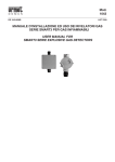
MANUALE D’INSTALLAZIONE ED USO DEI RIVELATORI SCR2
USER MANUAL FOR SCR2 GAS DETECTOR
ITALIANO
INDICE
1 INTRODUZIONE ................................................................................................................................................................................................. 2
1.1 Descrizione .................................................................................................................................................................................................. 2
1.2 Identificazione rivelatore .............................................................................................................................................................................. 2
1.3 Caratteristiche tecniche ............................................................................................................................................................................... 2
2 PREDISPOSIZIONE DEL SITO D’INSTALLAZIONE ........................................................................................................................................... 2
3 INSTALLAZIONE.................................................................................................................................................................................................. 3
3.1 Modalità per il corretto montaggio ............................................................................................................................................................... 3
3.2 Schema topografico..................................................................................................................................................................................... 3
3.3 Collegamento............................................................................................................................................................................................... 3
4 COLLAUDO E USO.............................................................................................................................................................................................. 3
4.1 Accensione .................................................................................................................................................................................................. 3
4.2 Collaudo....................................................................................................................................................................................................... 3
4.3 Uso .............................................................................................................................................................................................................. 3
5 MANUTENZIONE ................................................................................................................................................................................................. 3
5.1 Operazioni di manutenzione preventiva ..................................................................................................................................................... 3
5.2 Operazioni di manutenzione correttiva ....................................................................................................................................................... 4
5.3 Istruzioni per la dismissione ........................................................................................................................................................................ 4
6 ISTRUZIONI D’IMBALLO .................................................................................................................................................................................... 4
TAGLIANDO DI GARANZIA PER LA MODALITÀ DI RIPARAZIONE...................................................................................................................... 8
1 INTRODUZIONE
1.1 DESCRIZIONE
1.3 CARATTERISTICHE TECNICHE
I Rilevatori di gas della serie “SCR2” sono stati pensati e realizzati per
essere impiegati in ambito civile e industriale in area non classificata
(versione Dust IP55).
La loro funzione è quella di rilevare, in una atmosfera costituita
principalmente da aria, la presenza di sostanze combustibili o
Monossido di carbonio. La concentrazione di gas rilevata viene
visualizzata in concentrazioni esprimibili percentualmente in % LIE,
(Limite Inferiore di Esplosività) o ppm (parti per milione) sulle centrali
alle quali il sensore deve essere collegato.
Il sensore catalitico di tipo industriale utilizzato per il modello Sch.
1043/702 e la cella elettrochimica utilizzata sul modello Sch. 1043/706
conferiscono una precisione ed una selettività ottimale, evitando i falsi
allarmi e garantendo elevata affidabilità nel corso del tempo.
Alimentazione:
Campo di misura 1043/702:
Campo di misura 1043/706:
Assorbimento a 12 e 24Vcc 1043/702:
Assorbimento a 12 e 24Vcc 1043/706:
Uscita proporzionale:
Ripetibilità:
Temperatura di stoccaggio:
Temperatura operativa:
Umidità relativa:
Peso versione dust IP55:
Dimensioni dust IP55:
1.2 IDENTIFICAZIONE RIVELATORE
2 PREDISPOSIZIONE
D’INSTALLAZIONE
MODELLO
PROOF
USCITA
GAS RILEVATO
SENSORE
UTILIZZATO
DURATA
SENSORE
DS1043-029A
Sch. 1043/702
IP55
4-20mA
VAPORI
DI BENZINA
(VB)
Sch. 1043/706
IP55
4-20mA
MONOSSIDO
DI CARBONIO
(CO)
NEMOTO
NEMOTO
4 ANNI
2 ANNI
12-24 +/-10% Vdc +/-10%
0-100% LEL. VB
0-500 ppm CO
90-60mA
40 mA
4-20 mA
5% F.S.
-25 / + 60 °C
-10 / + 40 °C
0-90 % non condensata
400 gr.
L. 106, H. 180, P. 65 mm
DEL
SITO
Durante le operazioni di montaggio/installazione, gli impianti devono
essere messi in sicurezza. Ricordiamo anche come in fase di
installazione sia opportuno tenere in considerazione alcune norme
generali poiché un posizionamento non corretto può pregiudicare il
funzionamento ottimale del rivelatore.
Si raccomanda di non installare rivelatori gas nelle vicinanze di prese
d’aria e/o ventilatori che provocano forti correnti.
I rivelatori non devono essere altresì posti in zone nelle quali siano
presenti vibrazioni e, sebbene immuni da disturbi a radiofrequenze è
consigliabile non installarli in prossimità di emettitori radio (ponti radio
o apparecchiature simili).
Altra buona norma è quella di installare il rivelatore in zone facilmente
accessibili per le operazioni di test e calibrazione e per l’inserimento
dell’adattatore del kit di calibrazione.
I Vapori di benzina disperdendosi stazioneranno nella parte bassa
dell’ambiente ed il rivelatore deve quindi essere posizionato a 30-50
cm dal pavimento.
2
LBT 7630
Il Monossido di carbonio, avendo un peso specifica circa uguale
a quello dell’aria, può stazionare ad altezze non predefinite, quindi
installare il rivelatore ad una altezza di circa 1.60 mt. dal pavimento.
Nel caso vi siano giunzioni nel cavo di collegamento, assicurarsi che
vi sia continuità anche sulla schermatura dei cavi.
Ricordarsi che la schermatura deve essere collegata a terra unicamente
dal lato unità di controllo o gruppo di alimentazione, mentre non dovrà
mai essere collegata sui rilevatori.
Assicurarsi che la realizzazione di giunzioni sui cavi di alimentazione
mediante dispositivi di serraggio o a crimpare, sia eseguito a regola
d’arte con capicorda e/o morsetti che nel tempo non si ossidino o
allentino. È sempre preferibile eseguire giunzioni saldate.
Il rilevatore SCR2 può essere collegato a centrali di sicurezza di
qualsiasi tipo. Le prestazioni migliori si ottengono con una centrale di tipo
analogico 4-20 mA (o con un PLC) con indicazione proporzionale della
concentrazione di gas in ambiente.
Assicurarsi che la resistenza di carico del dispositivo di supervisione
non sia superiore a 200ohm.
Vi sono alcune sostanze che se presenti nella atmosfera da analizzare
possono alterare considerevolmente la risposta del sensore fino a
danneggiarlo irrimediabilmente (es. siliconi, silicati alogeni, tetraetile di
piombo, acido solfidrico, tetracloruro di carbonio tricloroetilene-trielina).
Allorché si presuma la presenza di queste sostanze, si consiglia di
verificare frequentemente e sempre dopo ogni intervento degli allarmi,
la sensibilità del rilevatore con gas di taratura.
Il rilevatore è calibrato in fabbrica specificamente per la sostanza
richiesta dal cliente. È successivamente possibile regolare il solo
segnale in assenza di gas (4mA) qualora dalla centrale venga
segnalata un’anomalia.
Per quanto riguarda i collegamenti elettrici, la morsettiera di tipo
estraibile semplifica e velocizza i collegamenti dei cavi di alimentazione
e segnale.
4 COLLAUDO E USO
4.1 ACCENSIONE
Assicurarsi che i collegamenti siano stati realizzati nel migliore dei modi.
Alimentare la centrale alla quale è collegato il rilevatore. La centrale
stessa permettere al rilevatore di scaldarsi per raggiungere le condizioni
ottimali di impiego. Sul rilevatore è presente un diodo led di colore
verde che indica la presenza della tensione di alimentazione.
Al momento dell’ accensione sono necessari 2 minuti circa prima che
la corrente erogata abbia un valore attendibile. Trascorso tale periodo
di tempo la corrente erogata dal rilevatore deve essere di 4,0 +/- 0,2
mA, in caso contrario è necessario aspettare 2 ore circa ed effettuare
la taratura del valore di Zero come descritto al punto 5.1.
3 INSTALLAZIONE
3.1 MODALITÀ PER IL CORRETTO MONTAGGIO
Il rilevatore deve essere installato tenendo la testa di rivelazione rivolta
verso il basso. Il contenitore del rivelatore, per nessuna ragione deve
essere forato; per il fissaggio utilizzare i fori già esistenti.
3.2 SCHEMA TOPOGRAFICO CIRCUITO
S1237
4.2 COLLAUDO
MORSETTIERA GENERALE
Verificare la risposta del rivelatore utilizzando una miscela a
composizione nota gas/aria, e l’apposito KIT di taratura.
-+S
LED VERDE
4.3 USO
Il rivelatore funziona automaticamente e autonomamente pertanto non è
richiesto alcun contributo da parte del suo utilizzatore.
P2 P3
5 MANUTENZIONE
TEST POINT
CONNETTORE SENSORE
P1
S1238
Tutti i RIVELATORI DI GAS sono stati calibrati utilizzando miscele di gas
campione. Se, trascorse 2 ore dal momento dell’ accensione, la corrente
erogata non fosse di 4,0 +/- 0.2mA si dovrebbe regolare il valore di zero
procedendo nel seguente modo:
MORSETTIERA GENERALE
-+S
P3
5.1 OPERAZIONI DI MANUTENZIONE PREVENTIVA
P1
LED VERDE
PER MODELLO Sch. 1043/702
Regolazione del valore di zero:
• scollegare il filo ‘S’ ed inserire in serie un amperometro;
• verificare che la corrente erogata dal rilevatore sia compresa tra 3,8
e 4,2 mA; diversamente procedere alla ritaratura del punto di zero
nel seguente modo:
• inserire un volmetro con fondo scala 20,0 mV sui terminali
del ‘TEST-POINT’. Regolare tale tensione a 0,0m Volt
utilizzando il trimmer ‘P2’.
• se il valore della corrente in uscita non fosse ancora
corretto, utilizzare P1 per ottenere 4.0 mA.
CONNETTORE SENSORE
Almeno 2 volte l’ anno è necessario verificare la risposta in gas del
rilevatore, procedendo nel seguente modo utilizzando l’apposito kit di
calibrazione:
• Applicare sulla testa rilevatrice del sensore il cappuccio di
calibrazione presente nel kit.
• Aprire la valvola in modo da far affluire gas e regolare il flusso
affinché la pallina contenuta all’interno del flussometro si posizioni
fra la prima e la seconda tacca.
• Aspettare circa due minuti e regolare P3 affinché la corrente erogata
dal rilevatore sia:
3.3 COLLEGAMENTO
Verificare che nella confezione ci siano tutte le parti componenti.
Per il collegamento del sensore con l’unità di elaborazione e
alimentazione si raccomanda l’uso di cavo schermato. La sezione del
cavo da utilizzare dipende dalla distanza del rilevatore dalla centrale:
• per distanze inferiori a 100 mt si usino cavi con sezione di 0.75 mm2;
• per distanze comprese fra 100 e 200 mt si usino cavi con sezione
di 1.0 mm2;
• per distanze comprese fra 200 e 300 mt si usino cavi con sezione
di 1.5 mm2.
DS1043-029A
• mA= (16/100 X (%in L.I.E di Metano contenuto nella
bombola) / F.C.) + 4.
• NOTA: F.C.( fattore di conversione)=1 per Metano.
• F.C.= 0.7 Vapori di benzina.
• il valore rilevato dalla prova in gas non deve avere uno
scostamento superiore al 5% dal valore calcolato.
3
LBT 7630
Esempio: se si dispone di una bombola di gas campione al 15.1%
L.I.E di Metano e si vuole calcolare la corrente erogata da un
rilevatore tarato per Vap. Benz., si ha:
• mA=(16/100*15.1 / 0.7)+4 = 7.45mA.
• il rilevatore è da ritenersi tarato se la differenza tra il valore
calcolato e la corrente erogata è compresa fra –5 e +5% del
fondo scala; ovvero fra 6,45 e 8,45 mA.
PER MODELLO Sch. 1043/706
Regolazione del valore di zero
• scollegare il filo ‘S’ ed inserire in serie un amperometro;
• verificare che la corrente erogata dal rilevatore sia compresa tra 3,8
e 4,2 mA ;diversamente procedere alla ritaratura del punto di zero
nel seguente modo:
• regolare P1 per ottenere 4.0 mA
Almeno 2 volte l’ anno è necessario verificare la risposta in gas del
rilevatore, procedendo nel seguente modo utilizzando l’apposito kit di
calibrazione:
• Applicare sulla testa rilevatrice del sensore il cappuccio di
calibrazione presente nel kit.
• Aprire la valvola in modo da far affluire gas e regolare il flusso
affinché la pallina contenuta all’interno del flussometro si posizioni
fra la prima e la seconda tacca.
• Aspettare circa due minuti e regolare P3 affinchè la corrente erogata
dal rilevatore sia:
• mA= (16/500 X (ppm CO contenuti nella bombola) + 4.
• il valore rilevato dalla prova in gas non deve avere uno
scostamento superiore al 5% dal valore calcolato.
Esempio: se si dispone di una bombola di gas campione di 325 ppm
CO e si vuole calcolare la corrente erogata dal rilevatore si ha:
• mA=(16/500 X 325)+4 = 14.4 mA.
• il rilevatore è da ritenersi tarato se la differenza fra il valore
calcolato e la corrente erogata è compresa fra –5 e +5% del
fondo scala; ovvero fra 13,4 e 15.4 mA.
5.2 OPERAZIONI DI MANUTENZIONE CORRETTIVA
Per anomalie riscontrabili durante il test funzionale rivedere la fase
di collaudo al capitolo 4. Se durante la manutenzione preventiva il
rilevatore non rileva il gas per cui è tarato, inviare il prodotto al fornitore
dello stesso che a sua volta provvederà ad inviarlo al costruttore.
5.3 ISTRUZIONI PER LA DISMISSIONE
Togliere alimentazione al rilevatore, scablare la morsettiera e rimuovere
il contenitore dalla tubatura metallica e dai relativi sistemi di
bloccaggio.
6 ISTRUZIONI D’IMBALLO
Per garantire la protezione agli urti si consiglia di imballarlo mediante
fogli di pallinato.
DS1043-029A
4
LBT 7630
ENGLISH
INDEX
1 INTRODUCTION .................................................................................................................................................................................................. 5
1.1 Description................................................................................................................................................................................................... 5
1.2 Detector identification code ......................................................................................................................................................................... 5
1.3 Technical specifications............................................................................................................................................................................... 5
2 INSTALLATION SITE PREARRANGEMENT....................................................................................................................................................... 5
3 INSTALLATION .................................................................................................................................................................................................... 6
3.1 Correct position mode.................................................................................................................................................................................. 6
3.2 Detector circuit layout .................................................................................................................................................................................. 6
3.3 Connection................................................................................................................................................................................................... 6
4 TESTING AND WORKING OPERATION............................................................................................................................................................. 6
4.1 Power ON .................................................................................................................................................................................................... 6
4.2 Testing ......................................................................................................................................................................................................... 6
4.3 Use .............................................................................................................................................................................................................. 6
5 MAINTANCE ........................................................................................................................................................................................................ 6
5.1 Preventive maintance routine ...................................................................................................................................................................... 6
5.2 Corrective maintance routine....................................................................................................................................................................... 7
5.3 Dismounting instruction ............................................................................................................................................................................... 7
6 PACKING INSTRUCTION .................................................................................................................................................................................... 7
WARRANTY COUPON FOR REPAIRING............................................................................................................................................................... 8
1 INTRODUCTION
1.1 DESCRIPTION
1.3 TECHNICAL SPECIFICATIONS
Gas detectors of “SCR2” line have been designed and realised to
be employed in commercial and industrial applications in either nonclassified areas (DUST PROOF IP55 rated).
SCR2 have been designed to detect gas contents in an atmosphere
mainly constituted by air. They can either detect explosive compounds,
or Carbon Monoxide (CO), with a concentration expressed in ppm
(parts per million).
The industrial type catalytic sensor employed in models Ref.
1043/702 and the electrochemical cell employed in Ref. 1043/706
offer a superior precision and selectivity, thus avoiding false alarms
and assuring an excellent reliability in time.
Power supply:
12-24 +/-10% Vdc +/-10%
Detectable range 1043/702:
0-100% LEL Gasoline Vapours
Detectable range 1043/706:
0-500 ppm CO
Current consumption at 12 and 24Vcc 1043/702:
90-60 mA
Current consumption at 12 and 24 Vcc 1043/706:
40 mA
Proportional output:
4-20 mA
Repeatability:
5% F.S.
Storage temperature:
-25 / + 60 °C
Operating temperature:
-10 / + 40 °C
Relative humidity:
0-90 % non condensing
Weight dust IP55 version:
400 gr.
Dimension dust IP55:
L. 106, H. 180, P. 65 mm
1.2 DETECTOR IDENTIFICATION CODE
MODEL
PROOF
OUTPUT
GAS DETECTED
SENSOR
EMPLOYED
SENSOR
LIFETIME
Ref. 1043/702
IP55
4-20mA
GASOLINE
VAPOURS
(VB)
Ref. 1043/706
IP55
4-20mA
CARBON
MONOXIDE
(CO)
NEMOTO
NEMOTO
4 YEARS
2 YEARS
2 INSTALLATION SITE PREARRANGEMENT
At the mounting/installation phase be sure all safety precautions have
been considered.
Always consider how important it is the correct positioning of gas
detectors to get the optimum response.
Be careful never to install gas detectors close to air intakes or fans
causing strong air currents.
Be sure the detectors are attached to a firm base to prevent vibration
that can damage them, producing unreliable results.
Although the electronics comply with the electromagnetic compatibility
rules, it is advised to keep the detectors at a distance from any radio
frequency senders (such as radio links or similar).
Ensure that the detectors are placed in a convenient location for future
maintenance and calibration requirements.
Gasoline vapours and all of the gases heavier than air tend to spread
downwards so the detector should be placed at 30 50 cm from the
floor.
DS1043-029A
5
LBT 7630
Carbon monoxide, having a specific weight approximately equal to
air’ should be detected at breathing level, and the detector should be
at approximately 1.60m above the floor to obtain a reliable protection.
Ensure the wire connections, either clutching or crimping type, are duly
carried out with terminals that do not oxidise or loosen. Better of all
would be to solder them.
The SCR2 gas detectors are designed to be connected to any control
unit accepting a 4-20 mA input signal, better when panels have an LC
display for the proportional readout of the concentration.
Please make sure the gas control panel load resistor be max 200 ohm.
There are some substances that, when present in the atmosphere being
analysed, can considerably change the response of the sensor and even
damage it irremediably, in particular silicones, silicon halides, tetraethyl
lead, hydrogen sulphide, carbon tetrachloride, trichlorethylene
Whenever their presence is presumed, it is recommended to check the
detector’s sensitivity at short time intervals, and always after an alarm
intervention, with sample gas bottles.
4 TESTING AND WORKING OPERATIONS
Detectors are factory calibrated for the specific gas required by the
customers. Future modification of the preset calibration can be carried
out in our Laboratory only, it being a procedure requiring specific
procedures and equipments.
The plug-in type terminal board make the wiring connection between
the detector and the control panel easy and fast.
4.1 POWER ON
Be sure that all connections have been correctly performed.
Power the control panel the detectors are connected to. On the
detector a green diode indicates the detector is powered.
The control panel will allow the detector to perform a warm-up phase
to reach the optimal working conditions. This phase will require nearly
2 minutes to be performed. After this time interval the current from the
detector must be 4,0 +/- 0,2 mA. Should not this value be attained
it is necessary to wait for 2 hours and perform the Zero adjustment
procedure as described on paragraph 5.1.
3 INSTALLATION
3.1 CORRECT POSITIONING MODE
The detector is always to be mounted with the sensing element placed
downward. For no reasons at all the enclosure can be drilled. Wall
mount the detectors by employing the existing holes.
4.2 TESTING
Testing should be carried out by using a gas mixture in the appropriate
range, along with our calibration kit.
3.2 DETECTOR CIRCUIT LAYOUT
S1237
4.3 USE
TERMINAL BOARD
The detector works autonomously and automatically. Once duly connected
no further operations are required, apart from periodical testing.
-+S
GREEN LED
5 MAINTENANCE
5.1 CORRECTIVE MAINTENANCE ROUTINES
P2 P3
TEST POINT
SENSOR CONNECTOR
P1
S1238
All GAS DETECTORS are calibrated with gas sample mixtures.
Should, after 2 hours from the power up, the current value from the
detector not attain 4,0 +/- 0,2 mA adjust the zero value as described
here below:
For model Ref. 1043/702
Zero value adjustment:
• Disconnect the wire ‘S’ and insert in series an Ammeter.
• Verify the current given by the detector is between 3,8 and 4,2 mA;
otherwise proceed at the zero point adjustment as follows:
TERMINAL BOARD
-+S
• Insert a voltmeter with full-scale 20.0mV on the ‘TESTPOINT’ terminal. Adjust this voltage to 0.0 mVolt by
operating on the ‘P2’ trimmer.
• Should not the output value be correct operate on ‘P1’
Trimmer to obtain 4.0mA.
GREEN LED
At least twice a year it is necessary to verify the detector response to
gas. Proceed as described here below, by employing our Calibration
Kit.
P3
P1
• Insert on the sensor head the calibration adapter.
• Turn on the gas valve to let the gas flow and set the flow-rate in
SENSOR CONNECTOR
order that the sphere inside the flow-meter is between the first and
second notch.
• Wait for a couple of minutes, then adjust P3 so that the current given
by the detector be:
3.3 CONNECTION
• mA= (16/100 X (LEL % Methane content stated on the gas
bottle / F.C.) + 4
• NOTE: F.C. (gain adjust value) = 1 for Methane.
• F.C.= 0.7 for Gasoline Vapours
• the value resulting from the gas test should not have a
deviation higher than 5% from the calculated value.
Please check the carton box comprises all of the components.
Wiring between the detector and the control panel should be carried
out with shielded cables. Wires’ cross section depends on the distance
between the control panel and the detector:
• for a distance up to m 100 we advice a 3 core wire with cross section
area of 0.75 mm2;
• for a distance between m 100 and 200 we recommend 3x1.0 mm2;
• for a distance between m 200 and 300 we recommend 3 x 1.5 mm2.
Example: should the sample gas bottle be at 15.1% LEL Methane
and you need to calculate the output current of a detector calibrated
to LPG, proceed as follows:
• mA=(16/100x15.1 / 0.7)+4 = 7.45mA
• The detector is to be considered as correctly calibrated if
the resulting value and the readout have a difference of
±5% full scale, which means between 6,45 and 8,45 mA
Should any junctions be necessary on the wires, please make sure
there is no interruption on the shield.
Please remember that the shield is to be connected to the ground from
the control panel side only. Also remember never to connect the shield
to the connectors
DS1043-029A
6
LBT 7630
For model Ref. 1043/706
Zero value adjustment:
• Disconnect the wire ‘S’ and insert in series an Ammeter.
• Verify the current given by the detector is between 3,8 and 4,2 mA;
otherwise proceed at the zero point adjustment as follows:
• operate on ‘P1’ Trimmer to obtain 4.0mA.
At least twice a year it is necessary to verify the detector response to
gas. Proceed as described here below, by employing our Calibration
Kit.
• Insert on the sensor head the calibration adapter.
• Turn on the gas valve to let the gas flow and set the flow-rate in order
that the sphere inside the flow-meter is between the first and second
notch.
• Wait for a couple of minutes, then adjust P3 so that the current given
by the detector be:
• mA= (16/500 x (ppm CO content in the gas can) + 4
• the value resulting from the gas test should not have a
deviation higher than 5% from the calculated value.
Example: should the sample gas bottle be at 325 ppm CO Methane and
you need to calculate the output current from the CO detector, proceed
as follows:
• mA=(16/500 X 325)+4 = 14.4 mA
• The detector is to be considered as correctly calibrated if the
resulting value and the readout have a difference of ±5% full scale,
which means between 13.4 and 15.4 mA
5.2 CORRECTIVE MAINTENANCE ROUTINES
For any anomaly found during the working test please check the tests
performances as described on chapter 4. If during the preventive
maintenance performances the detector does not react to the gas it
has been calibrated for, please return the instrument to your supplier
that on his turn will return it to the manufacturer for repair.
5.3 DISMOUNTING INSTRUCTION
Power the unit off, disconnect the wires on the terminals and dismount
the housing from any blocking systems.
6 PACKING INSTRUCTION
To grant a stout protection against impacts we recommend wrapping
the detector up in suitable packaging sheets.
DS1043-029A
7
LBT 7630
TAGLIANDO DI GARANZIA
MODALITÀ DI RIPARAZIONE
PER
LA
La garanzia sui prodotti Sensitron è valida un anno dalla data di
fabbricazione riportata sul prodotto. Si intende valida comunque per un
anno dalla data di installazione, purchè la stessa avvenga entro i dodici
mesi successivi la data di fabbricazione. Fanno fede il timbro e la
data posti dall’installatore sul presente modulo, che l’utilizzatore dovrà
debitamente conservare e rendere allo stesso in caso di verifiche
funzionali e riparazioni.
WARRANTY COUPON FOR REPAIRING
Warranty on Sensitron products is valid 1 one from the manufacturing
date placed on the product and it is extended of one year from the
date of the installation on condition that the installation is performed
within the first year of life of the product. As proof will be considered
the stamp and date of the installer placed on the present coupon which
is to be duly kept by the user and returned to the installer in case of
any working tests and repairs.
Data di installazione *
Installation date *
Modello/i
Model(s)
Numero/i di matricola
______________ ______________ ______________
Part Number(s)
______________ ______________ ______________
Timbro installatore
Installer Stamp
Firma installatore
Installer signature
* Utilizzare un singolo modulo per ogni data di installazione.
* Use one single coupon for any installation date
Nota Bene: si evidenzia che per i componenti deperibili installati
sui prodotti (sensori, batterie tampone in genere), la garanzia di
cui sopra è comunque vincolata e limitata ai termini di garanzia
dichiarati dalla casa costruttrice.
ATTENTION: Please be aware that all perishables installed in
our products (sensors, buffer batteries, etc.) benefit only of the
warranty conditions stated by the original manufacturer.
DS 1043-029A
LBT 7630
FILIALI
STABILIMENTO
20151 MILANO - Via Gallarate 218
Tel. 02.380.111.75 - Fax 02.380.111.80
00043 CIAMPINO (ROMA) - Via L.Einaudi 17/19A
Tel. 06.791.07.30 - Fax 06.791.48.97
URMET DOMUS S.p.A.
10154 TORINO (ITALY)
VIA BOLOGNA 188/C
Telef.
011.24.00.000 (RIC. AUT.)
Fax
011.24.00.300 - 323
Call Center 011.23.39.801
MT1237U
http://www.urmetdomus.com
e-mail:[email protected]