1
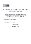
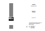
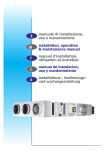
MANUALE DI INSTALLAZIONE,
USO E MANUTENZIONE
INSTALLATION, OPERATION &
MAINTENANCE MANUAL
UNITA’ TERMINALI CANALIZZABILI
DUCTED FAN COIL UNITS
SERIE BAW-BAW/V
SERIES BAW-BAW/V
Ed. 06/2008
SIMBOLOGIA / SYMBOLOGY
AVVERTENZA / ATTENTION
PERICOLO / DANGER
PERICOLO RISCHIO DI SCOSSE ELETTRICHE
HIGH RISK OF ELECTRIC SHOCK
ATTENZIONE SOLO PERSONALE AUTORIZZATO
ATTENTION AUTHORIZED PERSONNEL ONLY
Ed. 06/2008
Ed. 06/2008
MANUALE INSTALLAZIONE E MANUTENZIONE BAW PAG. 3
INTRODUZIONE
INTRODUCTION
Gentile Cliente,
Le unità terminali canalizzabili della serie BAW a
sviluppo orizzontale e BAW/V a sviluppo
verticale costituiscono la parte interna in impianti
a due sezioni.
Sono unità nate per applicazioni di tipo
residenziale e commerciale caratterizzate da
ridotte dimensioni e facilità di montaggio pari a
un ventilconvettore.
Proprio per le loro ridotte dimensioni, questa serie
è particolarmente indicata per l’installazione in
controsoffitto e comunque mai all’esterno.
Gli elettroventilatori centrifughi sono a tre
velocità con giranti bilanciate staticamente e
dinamicamente per ridurre al minimo le vibrazioni
e il rumore. Per la loro concezione tali unità
forniscono pressioni statiche utili disponibili
elevate, permettendo così il montaggio di
canalizzazioni per la distribuzione dell’aria
trattata in ambiente.
Questa soluzione consente di condizionare più
locali separati e adottando canali insonorizzati
permette di ottenere un’elevata silenziosità
dell’impianto con costi e tempi di messa in
funzione molto ridotti.
Dear Valued Client,
The horizontal BAW and vertical BAW/V ducted
fan coil units are the internal part of the two
section systems.
They are units developed for residential and
commercial situations, combining compact
dimensions with ease of installing equal to that of
a convector-fan.
Due to the units reduced dimensions, this series is
particularly ideal for lowered ceiling installation.
The series is not manufactured for external
installation.
The three speed electro-fans are statically and
dynamically balanced to reduce to a minimum
vibration and noise. By their design these units
supply a high level of available useful static
pressure, thus allowing duct fitting for the
distribution of treated air into the environment.
This solution gives the possibility to condition
more separated areas, and by using noise
reducing ducting, gives a high level of unit
silence, with reductions in costs and time needed
to place the unit into service.
Ed. 06/2008
MANUALE INSTALLAZIONE E MANUTENZIONE BAW PAG. 4
INDICE
INDEX
SEZIONE 1 – PRESENTAZIONE
SECTION 1 – PRESENTATION
1.1. Presentazione manuale
1.2. Identificazione macchina
pag. 6
pag. 6
1.1. Manual presentation
1.2. Machine identification
SEZIONE 2 – CARATTERISTICHE
SECTION 2 – TECHNICAL
TECNICHE
CHARACTERISTICS
2.1.
2.2.
2.3.
2.4.
2.5.
Caratteristiche generali
Accessori
Dimensioni unità
Dati tecnici unità
Dati tecnici accessori
pag. 7
pag. 7
pag. 8
pag. 10
pag. 12
SEZIONE 3 – TRASPORTO
3.1.
3.2.
3.3.
3.4.
Imballaggio
Movimentazione e trasporto
Controllo al ricevimento
Stoccaggio
2.1.
2.2.
2.3.
2.4.
2.5.
General characteristics
Accessories
Unit dimensions
Unit technical data
Accessories technical data
pag. 13
pag. 13
pag. 13
pag. 13
3.1.
3.2.
3.3.
3.4.
Packing
Transportation
Checklist
Storing
SECTION 4 – INSTALLATION &
IN SERVIZIO
CONNECTION
Definizioni
Norme di sicurezza
Operazioni preliminari
Scelta del luogo d’installazione
Collegamenti degli accessori
Posizionamento della macchina
orizzontale
4.7. Posizionamento della macchina
verticale
4.8. Collegamenti ai canali
4.9. Collegamenti idraulici
4.10.Collegamenti elettrici
4.11.Installazione accessori CVU e PCR
page 7
page 7
page 8
page 10
page 12
SECTION 3 – TRANSPORTATION
SEZIONE 4 – INSTALLAZIONE E MESSA
4.1.
4.2.
4.3.
4.4.
4.5.
4.6.
page 6
page 6
pag. 14
pag. 14
pag. 15
pag. 15
pag. 16
pag. 17
pag. 18
pag. 19
pag. 19
pag. 21
pag. 21
page 13
page 13
page 13
page 13
4.1. Definitions
4.2. Safety regulations
4.3. Preliminary operations
4.4. Choosing installation position
4.5. Connecting accessories
4.6. Horizontal machine positioning
4.7. Vertical machine positioning
4.8. Duct connection
4.9. Hydraulic connection
4.10.Electrical connection
4.11.Installation of CVU & PCR accessories
page 14
page 14
page 15
page 15
page 16
page 17
page 18
page 19
page 19
page 21
page 21
Ed. 06/2008
MANUALE INSTALLAZIONE E MANUTENZIONE BAW PAG. 5
SEZIONE 5 – SCHEMI ELETTRICI
5.1. Collegamento macchina 03-05-10
5.2. Collegamento unità grandezza 03-0510 a controllo velocità CVU
5.3. Collegamento unità grandezza 03-0510 con sezione SRE o 2SRE e pannello
di comando PCR
5.4. Collegamento macchina 12-13-14-1516-17-18
5.5. Collegamento unità grandezza 12-1314-15-16-17-18 a controllo velocità
CVU
5.6. Collegamento unità grandezza 12-1314-15-16-17-18 con sezione SRE o
2SRE a pannello di comando PCR
SECTION 5 – ELECTRICAL SCHEMES
pag. 25
pag. 25
pag. 27
pag. 27
pag. 28
page 25
page 25
page 27
page 27
page 28
page 29
pag. 29
SEZIONE 6 – CONTROLLI PRIMA
DELL’AVVIAMENTO
6.1. Controlli prima dell’avviamento
5.1. Machine connection 03-05-10
5.2. Connection of 03-05-10 units with CVU
speed control
5.3. Connection of 03-05-10 units with SRE
or 2SRE section and PCR control panel
5.4. Machine connection 12-13-14-15-1617-18
5.5. Connection of 12-13-14-15-16-17-18
units with CVU speed control
5.6. Connection of 12-13-14-15-16-17-18
units with SRE or 2SRE and PCR
control panel
SECTION 6 – PRE START CHECKLIST
pag. 30
SEZIONE 7 – MANUTENZIONE
6.1. Checks prior to initial start-up
page 30
SECTION 7 – STANDARD MAINTENANCE
ORDINARIA
7.1. Controlli mensili
7.2. Controlli annuali
pag. 31
pag. 32
SEZIONE 8 – LOCALIZZAZIONE DEI
7.1. Monthly maintenance
7.2. Yearly maintenance
page 31
page 32
SECTION 8 – TROUBLESHOOTING
GUASTI
8.1. Localizzazione dei guasti
pag. 32.
SEZIONE 9 – SMANTELLAMENTO
9.1. Smantellamento
8.1. Localisation of breakdowns
page 32
SECTION 9 – MATERIAL DISPOSAL
pag. 33
9.1. Material disposal
page 33
Ed. 06/2008
MANUALE INSTALLAZIONE E MANUTENZIONE BAW PAG. 6
SEZIONE 1 – PRESENTAZIONE
SECTION 1 – PRESENTATION
1.1 Presentazione manuale
1.1 Manual Presentation
Questo manuale riporta le informazioni e quanto ritenuto
necessario per il trasporto, l'installazione, l'uso e la
manutenzione delle macchine serie BAW e BAW/V prodotte
dalla ditta LMF Srl (in seguito chiamata anche Ditta
Costruttrice).
L’utente troverà quanto è normalmente utile conoscere per
una corretta installazione in sicurezza di tali unità.
La mancata osservanza di quanto descritto in questo manuale
e una inadeguata installazione delle BAW e BAW/V possono
essere causa di annullamento della garanzia che la Ditta
Costruttrice dà alle macchine.
La Ditta Costruttrice inoltre non risponde di eventuali danni
diretti e/o indiretti dovuti ad errate installazioni o per danni
causati dalle unità installate da personale inesperto e non
autorizzato.
Verificare, all'atto dell'acquisto, che la macchina sia integra e
completa.
Eventuali reclami dovranno essere presentati per iscritto entro
8 giorni dal ricevimento della merce.
This instruction manual supplies the necessary information
for the transportation, the installation, operation and
maintenance of the BAW & BAW/V series units as supplied
by the company LMF (from this point named as the supplier).
It supplies the user with as much information as is normally
useful for a correct and secure installation of the unit.
Lack of observation of the details found within this manual,
and an inadequate installation of the BAW & BAW/V units
may cause the withdrawal of the warranty supplied with the
equipment.
Furthermore, the Supplier will not respond to any eventual
damage, whether direct or indirect, caused by the incorrect
installation, or for damages caused by the installation being
effectuated by inexperienced or unauthorised personnel.
Verify, upon acquisition, that the apparatus is complete and
supplied as described.
Any eventual disputes must be presented in writing within 8
days from the reception of the goods.
1.2 Unit Identification
1.2 Identificazione macchina
Le unità BAW e BAW/V sono dotate di una targhetta di
identificazione che riporta:
Indirizzo del Costruttore;
Marcatura "CE";
Modello;
Numero di matricola;
Corrente assorbita massima in "A";
Tensione di alimentazione in "V";
Frequenza di alimentazione "Hz";
Numero di fasi indicato con "Ph";
Data di produzione;
Codice della macchina.
The BAW and BAW/V units are provided with identification
plate listing the following:
Address of Constructor;
“CE” Mark;
Model;
Serial Number;
Maximum Current absorbed in “A”;
Power supply voltage in “V”;
Power supply frequency in “Hz”;
Number of phases indicated with “Ph”;
Date of fabrication;
Unit Code.
Ed. 06/2008
MANUALE INSTALLAZIONE E MANUTENZIONE BAW PAG. 7
SEZIONE 2 – CARATTERISTICHE
SECTION 2 – TECHNICAL
TECNICHE
CHARACTERISTICS
2.1 Caratteristiche generali
2.1 General characteristics
•
•
•
•
•
•
•
Struttura realizzata in lamiera aluzink
Isolamento acustico e termico della macchina
ottenuto tramite un adeguato spessore di polietilene
e poliestere
Batteria di scambio termico ad acqua a 3 o 4 ranghi
realizzata con tubi di rame e alettatura in alluminio;
attacchi idraulici con filettatura GAS
Bacinella raccoglicondensa in acciaio inox
Eventuali filtri aria (in classe di efficienza G2 o
G4) facilmente estraibili per permettere la loro
periodica pulizia o sostituzione
Elettroventilatori centrifughi a tre velocità con
giranti
bilanciate
sia
staticamente
che
dinamicamente per ridurre al minimo le vibrazioni
e il rumore
Morsettiera esterna con scheda relè per facilitare i
collegamenti elettrici e il controllo dei ventilatori
(per il modello grandezza 10 non è presente la
scheda relè dati i bassi assorbimenti elettrici)
2.2 Accessori
-
Griglia di ripresa GAS
Plenum aspirante PAS
Sezione filtrante AF (efficienza G2)
Sezione filtrante FOS (efficienza G4)
Camera di miscela CM
Sezione di post-riscaldamento ad acqua SRW
Sezione di post-riscaldamento elettrico SRE o
2SRE
Plenum di mandata afonizzato PAM
Plenum di mandata per condotti flessibili PBC
Flangia di mandata per attacco ai canali FM
Bocchetta ad alette regolabili BRM
Controllo di velocità CVU
Pannello di controllo unità PCR
•
•
•
•
•
•
•
Unit casing made from ALUZINK sheet metal
Thermal and acoustic insulation made from
adequate thickness of polyethylene and polyester
The 3-row or 4-row water coil is copper tube &
aluminium fins type; water connections GAS
threaded
Stainless steel drip tray
Easily removable air filters (G2 or G4 efficiency
class as accessories)
Three-speed motor direct-driven fans, dynamically
and statically balanced to reduce to a minimum
vibration and noise
External electric box with a relay board fitted on
the unit to facilitate the electrical connections and
the fan control (on 10 size relay board excluded)
2.2 Accessories
-
Inlet grill GAS
Return plenum PAS
Filter section AF (G2 class efficiency)
Filter section FOS (G4 class efficiency)
Mixing chamber CM
Water reheating section SRW
Electric reheating section SRE or 2SRE
Sound proofed outlet plenum PAM
Round connection supply adapter PBC
Outlet flange attachment to ducts FM
Aluminium discharge spout with adjustable
winglets BRM
Speed control CVU
Unit control panel PCR
Ed. 06/2008
MANUALE INSTALLAZIONE E MANUTENZIONE BAW PAG. 8
2.3 Dimensioni unità
2.3 Unit dimensions
2.3.1 Dimensioni modelli orizzontali BAW
2.3.1 Horizontal BAW model dimensions
40
210
Scarico condensa Ø22 mm
35
C
80
35
90
A
15
N4
D1
D2
335
120
N2
N3
N1
50
17.5
L1
L2
L3
L2
L4
L6 L5
50
17.5
A
Modello / Model
A
B
C
D1 BAW
D2 BAW
N1
N2
N3
N4
N° bocche
L1
L2
L3
L4
L5
L6
PESO / Weight (Kg)
10
640
295
450
G¾
G¾
500
39
28
210
1
135
306
/
199
137
140
23
12-13
1000
295
450
G¾
G¾
860
39
28
210
2
139
290
186
95
135
136
33
36
14
1100
322
500
G¾
G¾
960
39
28
235
2
159
306
170
159
151
144
40
15
1340
322
535
G¾
G¾
1200
39
28
235
2
279
306
170
279
152
143
48
16-17
1340
372
535
G1
G1
1200
39
28
260
2
237
328
210
237
238
114
55
60
18
1640
372
535
G1
G1
1500
39
28
260
2
387
328
210
387
238
114
71
Ed. 06/2008
MANUALE INSTALLAZIONE E MANUTENZIONE BAW
2.3.2 Dimensioni modelli verticali BAW/V
50
PAG. 9
2.3.2 Vertical BAW/V model dimensions
A
D1
216
66
F1
69
70
288
F2
D2
70
66
Scarico condensa Ø22 mm
87
L3
L2
205
L4
L6 L5
L2
=
B
600
=
C
L1
Modello / Model
10
12-13
14
15
16-17
18
A
B
C
D1 BAW
D2 BAW
F1
F2
N° bocche
L1
L2
L3
L4
L5
L6
N° ranghi
PESO / Weight (Kg)
640
750
295
G 3/4
G 3/4
500
210
1
135
306
/
199
131
138
3
30
1000
750
295
G 3/4
G 3/4
826
210
2
127
306
170
91
150
128
1100
835
322
G 3/4
G 3/4
960
235
2
159
306
170
159
151
142
3
54
1340
950
322
G 3/4
G 3/4
1200
235
2
279
306
170
279
152
141
3
63
1340
950
372
G1
G1
1200
260
2
237
328
210
237
238
112
1640
950
372
G1
G1
1500
260
2
237
328
210
237
238
112
4
86
3
45
4
48
3
75
4
72
Ed. 06/2008
MANUALE INSTALLAZIONE E MANUTENZIONE BAW PAG. 10
2.4 Dati tecnici unità
2.4 Unit technical data
2.4.1 Caratteristiche aerauliche
2.4.1 Air performances
Modello / Size
Portata aria (∆)
Airflow rate (∆)
Prevalenza statica utile (∆)
External static pressure (∆)
Livello di pressione sonora a 1 m
Sound pressure level at 1 m
10
12
13
14
15
16
17
18
m3/h
950
1500
1600
2100
2400
3400
3800
4200
Pa
60
105
70
100
100
120
130
125
dB(A)
53,5
53,0
52,5
55,6
55,9
58,8
59,0
59,3
10
12
13
14
15
16
17
18
W
90
147
147
184
184
420
600
600
A
1
1,9
1,9
2,6
2,6
3,9
5,5
5,5
n°
3
3
3
3
3
3
3
3
n°
4
4
4
4
4
4
4
4
IP
20
20
20
20
20
20
20
20
B
B
B
B
B
B
B
B
Ventilatore / Fan motor
Potenza all'asse
Shaft power
Corrente max assorbita
Max current
N° velocità ventilatore
N° fan speeds
Poli
Poles
Grado di protezione
Protection degree
Classe di isolamento
Temperature class
Alimentazione elettrica
Electrical power supply
V/ph/Hz
230/1/50
(∆) alla massima velocità
(∆) at max fan speed
2.4.2 Prestazioni termiche e frigorifere
2.4.2 Heating & cooling capacities
Modello / Size
Potenza frigorifera(1)
Cooling capacity(1)
Potenza termica(2)
Heating capacity(2)
Perdita di carico lato acqua(3)
Water pressure drop(3)
Portata acqua(3)
Water flow rate(3)
10
12
13
14
15
16
17
18
W
4290
7030
8900
9400
11090
14250
18940
22270
W
9770
15790
18660
21420
25050
33530
41710
47510
kPa
28
21
27
28
28
22
32
30
l/h
736
1204
1525
1610
1899
2441
3244
3816
(1)
Aria in ingresso a 27°C BS 19°C BU – Acqua: ingresso
7°C uscita 12°C
(2)
Aria in ingresso 20°C bs – Acqua: ingresso 70° uscita 60°
(3)
In modalità raffreddamento
(1)
Air inlet 27°C DB 19°C WB – Water temperature: in 7°C
out 12°C
(2)
Air inlet 20°C DB – Water temperature: in 70° out 60°
(3)
Cooling mode
Ed. 06/2008
MANUALE INSTALLAZIONE E MANUTENZIONE BAW PAG. 5
2.5 Accessories technical data
2.5 Dati tecnici accessori
Sezione riscaldamento elettrico SRE
Electrical heating section SRE
Potenza termica
Heat capacity
Alimentazione elettrica
Electrical power supply
Sezione riscaldamento elettrico 2SRE
Electrical heating section 2SRE
Potenza termica
Heat capacitys
Alimentazione elettrica
Electrical power supply
Sezione riscaldamento ad acqua SRW
Water re-heating section SRW
Potenza termica
Heat capacity
Perdita di carico lato acqua
Water pressure drop
Portata acqua
Water flow rate
kW
10
12
13
14
15
16
17
18
3
4,5
4,5
4,5
6
6
6
6
V/f/Hz
kW
400/3/50
10
12
13
14
15
16
17
18
6
9
9
9
12
12
12
12
V/f/Hz
400/3/50
10
12
13
14
15
16
17
18
W
7880
13160
13750
17600
21910
27460
29500
31440
kPa
12
18
19
17
22
25
29
32
m3/h
0,693
1,159
1,211
1,548
1,927
2,416
2,594
2,766
Ed. 06/2008
MANUALE INSTALLAZIONE E MANUTENZIONE BAW PAG.
SEZIONE 3 – TRASPORTO
SECTION 3 – TRANSPORTATION
3.1 Imballaggio
3.1 Packing
Le unità trattamento aria e i loro accessori sono inseriti in
scatole di cartone che dovranno rimanere integre fino al
momento del montaggio.
I materiali che non sono stati installati per esigenze tecniche
vengono forniti imballati con involucro idoneo fissato
all'interno o esterno dell'unità stessa.
The air treatment unit and accessories are packed in
cardboard boxes; this packing should remain intact until the
moment of construction.
The materials that are not required for technical motives are
supplied in fitted packing fixed externally and internally to
the unit.
3.2 Movimentazione e trasporto
3.2 Transportation
Per la movimentazione utilizzare, in funzione del peso mezzi
adeguati come previsto dalla direttiva 89/391/CEE e
successive modifiche.
Il peso di ogni singola macchina è riportato sul seguente
manuale.
Evitare rotazioni senza controllo.
For the lifting and transportation of the unit, use adequate
equipment, according to the 89/391/CEE regulations and
successive modifications.
Each individual machine weight is listed in this manual.
Avoid rotation without control.
3.3 Controllo al ricevimento
3.3 Checklist
Al ricevimento dell’unità Vi preghiamo di effettuare un
controllo di tutte le parti, al fine di verificare che il trasporto
non abbia causato danneggiamenti, i danni eventualmente
presenti devono essere comunicati al vettore, apponendo la
clausola di riserva nella bolla di accompagnamento,
specificandone il tipo di danno.
Upon reception of the apparatus, we suggest that a complete
control is carried out, to verify that the unit is intact and
complete, and no damage has been sustained during
transport. Any eventual damage revealed must be
communicated to the carrier, demonstrating the reserve
clause within the transport documents, specifying the type of
damage.
3.4 Stoccaggio
3.4 Storing
In caso di stoccaggio prolungato mantenere le macchine
protette dalla polvere e lontano da fonti di vibrazioni e di
calore.
In case of long term storage, the apparatus must be kept free
from dust, and away from areas susceptible to heat and
vibration.
La ditta costruttrice declina ogni responsabilità per
danneggiamenti dovuti a cattivo scarico o per mancata
protezione dagli agenti atmosferici.
The manufacturer declines any responsibility for any
damage as a result of negligence or lack of protection from
atmospheric agents.
Ed. 06/2008
MANUALE INSTALLAZIONE E MANUTENZIONE BAW PAG.
SEZIONE 4 – INSTALLAZIONE E MESSA
SECTION 4 – INSTALLATION &
IN SERVIZIO
CONNECTION
4.1 Definizioni
4.1 Definition
UTENTE – L’utente è la persona, l'ente o la società, che ha
acquistato o affittato la macchina e che intende usarla per gli
scopi concepiti.
CLIENT– The client is the person, activity or the society,
that has bought or hired the apparatus, and intends to utilise
the machinery for its intended use.
UTILIZZATORE / OPERATORE – L’utilizzatore o
operatore, è la persona fisica che è stata autorizzata
dall'utente a operare con la macchina.
USER / OPERATOR – The User or Operator, is the actual
person that has been authorised by the client to utilise the
apparatus.
PERSONALE SPECIALIZZATO - Come tali, si intendono
quelle persone fisiche che hanno conseguito uno studio
specifico e che sono quindi in grado di riconoscere i pericoli
derivati dall'utilizzo di questa macchina e possono essere in
grado di evitarli.
TECHNICIAN – Defined as the person who has followed a
relevant/specific course of study, and so is able to understand
the dangers derived from the use of the apparatus, and in
turn, due to this, are capable of solving major dilemmas.
4.2 Norme di sicurezza
4.2 Safety regulations
La Ditta Costruttrice declina qualsiasi responsabilità per
la mancata osservanza delle norme di sicurezza e di
prevenzione di seguito descritte.
Declina inoltre ogni responsabilità per danni causati da
un uso improprio delle unità e/o da modifiche eseguite
senza autorizzazione.
•
•
•
•
•
•
•
L'installazione deve essere effettuata da
personale specializzato.
Nelle operazioni di installazione, usare un
abbigliamento idoneo e antinfortunistico, ad
esempio: occhiali, guanti, ecc. come indicato da
norma 686/89/CEE e successive.
Durante l’installazione operare in assoluta
sicurezza, ambiente pulito e libero da impedimenti.
Rispettare le leggi in vigore nel Paese in cui viene
installata la macchina, relativamente all'uso e allo
smaltimento dell'imballo e dei prodotti impiegati
per la pulizia e la manutenzione della macchina,
nonché osservare quanto raccomanda il produttore
di tali prodotti.
Prima di mettere in funzione l’unità controllare la
perfetta integrità dei vari componenti e dell'intero
impianto.
Evitare assolutamente di toccare le parti in
movimento o di interporsi tra le stesse.
Non procedere con i lavori di manutenzione e di
pulizia, se prima non è stata disinserita la linea
elettrica.
The Manufacturer declines any responsibility for failure to
respect the Safety Regulations, and the prevention as
described below.
Furthermore, the manufacturer declines any responsibility
for damage caused by the improper use of the unit and/or
modifications carried out without proper authorisation.
•
•
•
•
•
•
•
Qualified personnel must carry out the
installation.
During the installation operation, use protective
clothing, for example: glasses, gloves, etc. as
indicated by 686/89/CEE and successive
regulations.
During the installation operate in absolute security,
pollution free air and in an area free of
obstructions.
Respect the regulations in force in the country in
which the apparatus is being installed. Specifically
relative to its use, and to the disposal of packing
and products used for the cleaning and
maintenance
of
the
unit.
Respect
the
recommendations given by the producers of such
products.
Before placing in function the unit, check the
perfect connection of the various components and
the internal parts of the system.
Avoid at all costs human contact with moving parts
and contact with the parts themselves.
Do not commence with servicing or cleaning of
the unit, before the unit has been disconnected
from the main supply.
Ed. 06/2008
MANUALE INSTALLAZIONE E MANUTENZIONE BAW PAG.
•
•
•
La manutenzione e la sostituzione delle parti
danneggiate o usurate deve essere effettuata
solamente da personale specializzato e seguendo le
indicazioni riportate in questo manuale.
Le parti di ricambio devono corrispondere alle
esigenze definite dal Costruttore.
In caso di smantellamento delle unità, attenersi alle
normative antinquinamento previste.
•
•
The maintenance and the substitution of damaged
or consumed parts must be carried out only by
specialised personnel, following the indications
found within this manual.
Spare parts must correspond to the requirements
specified by Manufacturer.
In case of dismantling of the unit, respect the antipollution regulations in force.
N.B. L’installatore e l’utilizzatore nell’uso dell’unità devono
tenere conto e porre rimedio a tutti gli altri tipi di rischio
connessi con l’impianto. Ad esempio rischi derivanti da
ingresso di corpi estranei, oppure rischi dovuti al
convogliamento di gas pericolosi infiammabili o tossici ad
alta temperatura.
N.B. The installer and the user of the apparatus must take
into account, and solve problems, connected with any other
type of risk that may occur to the unit. For example, risks
derived from the entrance of foreign bodies, or risks due to
the presence of flammable or toxic gas.
4.3 Operazioni preliminari
4.3 Preliminary operations
•
•
•
•
Verificare la perfetta integrità dei vari componenti
dell'unità.
Controllare che nell’imballo ci siano contenuti gli
accessori per l'installazione, e la documentazione.
Trasportare la sezione imballata il più vicino
possibile al luogo di installazione.
Non sovrapporre attrezzi o pesi sull'unità imballata.
4.4 Scelta del luogo d’installazione
•
•
•
•
Posizionare l'unità su di una struttura solida che
non causi vibrazioni e che sia in grado di
sopportare il peso della macchina.
Posizionarla in un punto in cui lo scarico della
condensa possa avvenire facilmente.
Non posizionare l’unità in locali in cui sono
presenti gas infiammabili, sostanze acide,
aggressive e corrosive che possono danneggiare i
vari componenti in maniera irreparabile.
Prevedere uno spazio libero minimo come indicato
in figura al fine di rendere possibile l’installazione
e la manutenzione ordinaria e straordinaria.
Versione orizzontale
Versione orizzontale
•
•
•
•
Check the perfect condition of the various
components of the unit.
Control that contained within the packing, there
are
the
installation
accessories,
and
documentation.
Transport the packed section as close as is possible
to the intended place of installation.
Do not place tools or weight on top of the packed
unit.
4.4 Choosing installation position
•
•
•
•
Position the unit on a solid structure, that will not
vibrate, and is capable supporting the weight of the
machine.
Position the unit in a point where the condensation
discharge may occur easily.
Do not position the unit in an area in which
flammable gases, acidic or corrosive substances
are present. They may damage various components
in an irreparable manner.
Allow a minimum amount of free space as indicated
in the figure. This permits ease of installation and
maintenance.
Versione verticale
Versione verticale
•
Ed. 06/2008
MANUALE INSTALLAZIONE E MANUTENZIONE BAW PAG.
4.5 Collegamento degli accessori
4.5 Connecting accessories
Per il fissaggio degli accessori sulla
unità base sono state previste delle viti
filettate M6. Allentare queste viti di 4-5
giri.
For the fixing of the accessories onto
the base unit, M6 thread screws are
provided. Tighten screws by 4-5 turns.
Tutti gli accessori presentano dei fori a
chiave che consentono di fissare gli
stessi all’unità base
All accessories have keyholes that
ease fitting to base unit.
Porre l’accessorio di fronte all’unità
base e far coincidere i fori a chiave con
le teste della vite.
Place accessory in front of base unit,
and line up keyholes with screws.
Posto l’accessorio sull’unità base
spingere lateralmente lo stesso fino a
bloccarlo.
Place accessory on base unit and push
laterally until the position is blocked.
Togliere i tappi in plastica posti sul
fianco e bloccare con una chiave le viti.
Remove plastic side plugs and tighten
bolts
Ed. 06/2008
MANUALE INSTALLAZIONE E MANUTENZIONE BAW PAG.
4.6 Posizionamento della macchina orizzontale
4.6 Horizontal unit positioning
Le unità sono corredate da piastre di supporto antivibranti
Qui di seguito sono indicate alcune sequenze del montaggio:
1. Eseguire la foratura a soffitto e fissare quattro
tiranti filettati M8 come indicato in figura.
2. Posizionare l’unità sui quattro tiranti usufruendo
delle apposite staffe di fissaggio.
3. Bloccare l’unità serrando i bulloni di fissaggio.
The unit is equipped with anti-vibration support plates.
As follows are indications the various sequence of assembly:
1. Carry out the drilling of the ceiling, and fit the four
M8 threaded bolts as indicated in the diagram.
2. Position the unit on the four bolts using the
supplied fixing plates.
3. Block the unit tightening the fixing bolts..
Tirante
Dado
Rondella
Staffa
Antivibrante
Dado
Rondella
Dado
B
A
Modello / Model
10
12/13
14
15/16/17
18
A (mm)
675
1035
1135
1375
1675
B (mm)
335
335
335
335
335
Allo scopo di favorire il regolare deflusso della condensa si
consiglia di montare la macchina inclinata di 3mm verso lo
scarico condensa.
To aid the regular flow of the condensation, it is advised to
install the apparatus with a 3mm inclination towards the
condensation outlet.
Ed. 06/2008
MANUALE INSTALLAZIONE E MANUTENZIONE PAG. 18
4.7 Posizionamento della macchina verticale
4.7 Vertical unit positioning
Le unità sono corredate di staffe per il fissaggio a muro
Qui di seguito sono indicate alcune sequenze del montaggio:
1. Eseguire le forature a muro rispettando le quote
indicate in figura.
2. Unire l’unità con staffe di fissaggio.
3. Bloccare l’unità fissando quattro viti a muro (non
fornite).
The unit is equipped with anti-vibration support plates.
As follows are indications the various sequence of assembly:
1. Carry out the drilling of the ceiling, and fit the four M8
threaded bolts as indicated in the diagram.
2. Position the unit on the four bolts using the supplied
fixing plates.
3. Block the unit tightening the fixing bolts.
600
B
(x4
)
A
0
Ø1
Modello / Size
10
12 / 13
14
15 / 16 / 17
18
A (mm)
75
75
117.5
175
175
B (mm)
680
1040
1140
1380
1680
Ed. 06/2008
MANUALE INSTALLAZIONE E MANUTENZIONE PAG. 19
4.8 Collegamento ai canali
IMPORTANTE: SI FA DIVIETO DI METTERE
IN FUNZIONE L’UNITA’ SE LE BOCCHE DEI
VENTILATORI NON SONO CANALIZZATE O
PROTETTE CON RETE ANTINFORTUNISTICA
A NORMA UNI 9219 E SUCCESSIVE.
•
•
•
I canali devono essere dimensionati in funzione
dell’impianto e delle caratteristiche aerauliche dei
ventilatori dell’unità. Un errato calcolo delle
canalizzazioni causa perdite di potenza o
l’intervento di eventuali dispositivi presenti
sull’impianto.
Per prevenire la formazione di condensa ed
attenuare il livello di rumorosità si consiglia di
utilizzare canali coibentati.
Per evitare di trasmettere le eventuali vibrazioni
della macchina in ambiente, è consigliato interporre
un giunto antivibrante fra le bocche ventilanti e i
canali. Deve comunque essere garantita la
continuità elettrica fra canale e macchina tramite un
cavo di terra.
4.9 Collegamenti idraulici
•
•
•
•
•
•
•
Le operazioni di installazione e collegamento delle
tubazioni
sono
operazioni
che
possono
compromettere
il
buon
funzionamento
dell’impianto o peggio, causare danni irreversibili
alla macchina. Queste operazioni sono da
effettuarsi da personale specializzato.
Le unità BAW-BAW/V sono fornite di attacchi
“maschio” con filettatura gas, mentre le sezioni di
post-riscaldamento ad acqua SRW hanno attacchi
maschio filettati gas G 3/4.
Le operazioni di serraggio vanno effettuate con
cautela onde evitare danni.
Il percorso dei tubi deve essere studiato in modo da
non creare ostacoli in caso di estrazione della
batteria o del filtro dall’unità.
Entrata e uscita acqua devono essere tali da
consentire lo scambio termico in controcorrente:
seguire quindi le indicazioni delle targhette
ENTRATA ACQUA e USCITA ACQUA.
Prevedere una valvola in basso per lo scarico
dell’acqua contenuta nella batteria.
Staffare adeguatamente i tubi all'esterno della unità
per evitare di scaricarne il peso sui collettori della
batteria.
4.8 Duct connection
IMPORTANT: IT IS IMPORTANT NOT TO PLACE
IN OPERATION THE UNIT IF THE FAN
OUTLETS ARE NOT DUCTED OR NOT
PROTECTED BY A SAFETY NET ADHERING
WITH REGULATION UNI 9219 OR SUCCESSIVE.
•
•
•
The Ducts must be the correct dimension based on
the functions of system and the air diffusion
characteristics of the unit fans. A mistaken
calculation of the ducting will cause power loss or
the intervention of any eventual devices present on
the system.
To prevent the formation of condensation and cut
down the sound level it is advised to use internally
lined Ducts.
To avoid the transmission of machine vibrations
into the environment, it is advised to fit an antivibration joint between the fans and Ducts. The
electrical continuity must be guaranteed between
the Ducts and the apparatus via an earth cable
4.9 Hydraulic connection
•
•
•
•
•
•
•
The installation and connecting of the piping is an
operation that must be done correctly, otherwise it
may compromise the performance of the system. At
worst it may cause irreversible damage to the
machine. These operations are to be effectuated by
qualified personnel.
The BAW-BAW/V units are supplied with “male”
connections with GAS threads, whilst the water
reheating section SRW have male G ¾ GAS
threads.
Extreme caution must be taken during the
installation operation, to avoid damage.
The tube path must be studied in such a way to not
create obstacles should an eventual extraction of
unit coil or filter be required.
Water inlet and outlet must occur allowing the
thermal exchange in counterflow: follow the
indications found on the WATER INLET and
WATER OUTLET plate.
Supply a lower valve for the emptying of the water
contained in the coil.
Fix securely the tubes to the outside of the unit, so
as to avoid offloading the weight onto the coil
collectors.
Ed. 06/2008
MANUALE INSTALLAZIONE E MANUTENZIONE PAG. 20
•
•
•
•
A collegamento effettuato spingere bene la
guarnizione esterna in gomma contro il pannello
per evitare trafilamenti d'aria.
La coibentazione deve giungere a filo pannello per
evitare pericolo di scottature.
Prevedere valvole di intercettazione per isolare la
batteria dal resto dei circuito in caso di
manutenzione straordinaria.
Nel caso di installazione in zone con climi
particolarmente freddi, svuotare l’impianto in
previsione di lunghi periodi di ferma dell’impianto.
4.9.1 Collegamento scarico condensa
•
•
•
•
•
•
•
•
•
•
Once the connection has been followed, fix the
external rubber seals against the panel to avoid
passing of air.
The lining must just rest on the panel, to avoid the
risk of burning.
Supply an interception valve to isolate the coil from
the rest of the circuit in case of extraordinary
maintenance.
Should the installation of the apparatus occur in
areas with particularly cold climates, empty the
system prior to an extended period of inutilization.
4.9.1 Condensation outlet connection
La vasca di raccolta condensa in acciaio inox è
provvista di scarico D. 22 mm.
Un sistema di scarico deve prevedere un adeguato
sifone per prevenire l'indesiderata entrata d'aria nel
sistema in depressione. Tale sifone risulta inoltre
utile per evitare l'infiltrarsi di odori o insetti.
Il dimensionamento e l'esecuzione del sifone deve
garantire che H ≥ P, dove P espresso in mm.c.a, è
pari alla pressione statica utile della macchina
installata.
•
Il sifone deve infine essere dotato di tappo per la
pulizia nella parte bassa o deve comunque
permettere un veloce smontaggio per la pulizia.
Il percorso del tubo di scarico condensa deve avere
sempre un pendenza verso l’esterno.
Assicurarsi che il tubo per il deflusso della
condensa non solleciti l’attacco di scarico
dell’unità.
•
•
•
•
•
The condensation drip tray in stainless steel inox
has a depth of D. 20 mm.
The system of drainage must provide an adequate
trap to prevent the undesirable entrance of air into
the system in depression. The trap is also useful to
avoid the infiltration of odours and insects.
The dimensions and execution of the trap must
guarantee that H ≥ P, where P is expressed in
mm.c.a, and is equal to the useful static pressure of
the unit installed.
The trap must have a tap for correct cleaning of the
lower part, and must allow an easy disassembly.
The path of the condensation drainage tube must
always have a gradient toward external.
Insure that the condensation run-off tube does not
interfere with discharge of the unit.
Ed. 06/2008
MANUALE INSTALLAZIONE E MANUTENZIONE PAG. 21
4.10 Collegamenti elettrici
4.10 Electrical connection
Prima di iniziare qualsiasi operazione
assicurarsi che la linea di alimentazione
generale sia selezionata.
•
•
I collegamenti elettrici ai quadri di comando
devono essere effettuati da personale specializzato
secondo gli schemi forniti.
Assicurarsi che la tensione e la frequenza riportate
sulla targhetta corrispondano a quelle della linea
elettrica di allacciamento.
Eseguire il collegamento dell’unità e di tutti i suoi accessori
con cavi di sezione adeguata alla potenza impegnata e nel
rispetto delle normative locali. La loro dimensione deve
comunque essere tale da realizzare una caduta di tensione in
fase di avviamento inferiore al 3% di quella nominale.
•
•
•
Per l’alimentazione generale dell'unità e degli
accessori non è consentito l’uso di adattatori, prese
multiple e/o prolunghe.
E’ dovere dell’installatore prevedere il
montaggio il più vicino possibile all’unità di un
sezionatore
dell’alimentazione
e
quanto
necessario per la protezione delle parti
elettriche.
Collegare l’unità ad una efficace presa di terra,
utilizzando l’apposita vite inserita nell’unità stessa.
Before commencing any operation,
insure that the general power supply has
been isolated.
•
•
Qualified personnel according to the supplied
schemes must carry out the electrical connections
at the control panel.
Insure that the voltage and the frequency shown on
the technical plate correspond to the connecting
power supply.
Follow the connection of the unit and its accessories
using adequate cabling for the power used, and
respecting the country regulations. The dimension of
the cabling must be sufficient to support a voltage drop
in start up phase inferior to 3% of the nominal.
•
•
•
For the general power supply of the unit, and its
accessories, the use of adapters, multiple plugs and
extension leads is to be avoided.
It is the responsibility of the installer to insure
that the installation of the unit is as close as
possible to the mains power supply, or sufficiently
close to protect the electrical parts.
Connect the unit to an efficient power point, using
the correct screws as supplied with the unit.
4.11 Installazione accessori CVU e PCR
4.11 Installation of CVU and PCR accessories
4.11.1 Controllo di velocità CVU
4.11.1 CVU Speed control
Adatto per l’installazione a parete, consente di selezionare
una delle tre velocità del ventilatore.
Suitable for wall installation, allows the possibility to select
one of three fan speeds.
Sul pannello di comando sono presenti:
interruttore acceso - spento;
commutatore a tre posizioni delle velocità.
Present on the control panel is:
On – Off switch;
Three speed Selector switch.
Ed. 06/2008
MANUALE INSTALLAZIONE E MANUTENZIONE PAG. 22
Caratteristiche tecniche
Technical characteristics
230 +/- 10% Vac; 50-60 Hz
Acceso-Spento / On-Off switch
Commutazione manuale velocità / Manual fan speed selection
Alimentazione / Power supply
Controlli / Controls
4.11.2 Pannello di controllo unità PCR
4.11.2 PCR Unit control panel
Adatto per l’installazione a parete, consente il controllo della
temperatura ambiente sia in regime estivo che invernale,
inoltre permette l’esclusione o l’attivazione della resistenza
elettrica
e
la
selezione
delle
tre
velocità
dell’elettroventilatore.
Suitable for wall installation, it allows room temperature
control, for both summer and winter, furthermore it can
control (on-off mode) the possible electric heater SRE or
2SRE and the fan speeds.
Sul pannello di comando sono presenti:
manopola della regolazione della temperatura;
display digitale con comandi per impostare parametri di
esercizio
On the control panel:
thermostat;
display and keyboard for setting working parameters
Caratteristiche tecniche
Technical characteristics
Alimentazione / Power supply
230 +/- 10% Vac; 50-60 Hz
Controlli / Controls
Commutazione Estate/Inverno manuale o automatica / Manual or automatic Summer/Winter mode
Commutazione 3 velocità manuale o automatica / Manual or automatic fan speed selection
Ed. 06/2008
MANUALE INSTALLAZIONE E MANUTENZIONE PAG. 25
SEZIONE 5 – SCHEMI ELETTRICI
SECTION 5 – ELECTRICAL SCHEMES
5.1 Collegamento macchina grandezza 03-0510
5.1 Machine connections 03-05-10
Nello schema è indicato il funzionamento alla massima velocità.
Per il funzionamento alla media velocità collegare il neutro con il blù,
per la bassa velocità collegare il neutro con il rosso.
The maximum speed operation is indicated in the diagram. For the medium speed
operation connect the neutral to the blue, for low speed connect the neutral to the red.
I COLLEGAMENTI A CURA DELL'INSTALLATORE SONO INDICATI A TRATTEGGIO. TUTTE LE LINEE DEVONO ESSERE
PROTETTE ALL'ORIGINE A CURA DELL'INSTALLATORE.
THE CONNECTIONS TO BE CARRIED OUT BY THE INSTALLER ARE SHOWN BY THE DOTTED LINE. ALL THE
CONNECTIONS MUST BE PROTECTED AT THE SOURCE BY THE INSTALLER.
5.2 Collegamento unità grandezza 03-05-10 al
controllo velocità CVU
5.2 Connection of 03-05-10 units with CVU
speed control
Ed. 06/2008
MANUALE INSTALLAZIONE E MANUTENZIONE PAG. 26
5.3 Collegamento unità grandezza 03-05-10 al
pannello di comando PCU
5.3 Connection of 03-05-10 units with PCU
control panel
5.4 Collegamento unità grandezza 03-05-10 con
sezione SRE o 2SRE e pannello di comando
PCU
5.4 Connection of 03-05-10 units with SRE or
SRE2 section and PCU control panel
T
S
R
N
PCU
1
R
S
3
4
5
6
7
8
9
10 11 12 13
T
R1 S1 T1
KMR1
2
TS
TS
2
TS
TS
3
R2 S2 T2
KMR2
M
COMUNE / COMMON
ALTA VELOCITA' / HIGH SPEED
MEDIA VELOCITA' / MEDIUM SPEED
BASSA VELOCITA' / LOW SPEED
QUADRO COMANDO SRE SINGOLA / DOPPIA RESISTENZA
SRE CONTROL CABINET
QUADRO COMANDO VENTILATORI
CONTROL PANEL FAN
I COLLEGAMENTI A CURA DELL'INSTALLATORE SONO INDICATI A TRATTEGGIO.
TUTTE LE LINEE DEVONO ESSERE PROTETTE ALL'ORIGINE A CURA DELL'INSTALLATORE
THE CONNECTION TO BE CARRIED OUT BY THE INSTALLER ARE SHOWN BY THE DOTTER LINE.
ALL THE CONNECTIONS MUST BE PROTECTED AT THE SOURCE BY THE INSTALLER.
Ed. 06/2008
MANUALE INSTALLAZIONE E MANUTENZIONE PAG. 27
5.5 Collegamento unità grandezza 03-05-10 con
sezione SRE o 2SRE e pannello di comando
PCUR
5.5 Connection of 03-05-10 units with SRE or
SRE2 section and PCUR control panel
T
S
R
N
PCUR
1
2
3
4
5
6
7
8
9
N
L
10 11 12 13
SM
2
R S T
All' elettrovalvola
KMR2
KMR2
TS
TS
TS
TS
KMR1
3
QUADRO A BORDO UNITA'
INTERNA
CABINET AT THE SIDE OF
THE UNIT
VENTILATORE A TRE
VELOCITA'
THREE SPEED FAN
GIALLO VERDE / YELLOW GREEN
KMR1
BIANCO-COMUNE/WHITE-COMMON
M
NERO-ALTA VELOCITA'/BLACK-HIGH SPEED
BLU-MEDIA VELOCITA'/BLUE-MEDIUM SPEED
ROSSO-BASSA VELOCITA'/RED-LOW SPEED
SRE
I COLLEGAMENTI A CURA DELL'INSTALLATORE SONO INDICATI A TRATTEGGIO. TUTTE LE
LINEE DEVONO ESSERE PROTETTE ALL'ORIGINE A CURA DELL'INSTALLATORE
THE CONNECTIONS TO BE CARRIED OUT BY THE INSTALLER ARE SHOWN BY THE DOTTED
LINE. ALL THE CONNECTIONS MUST BE PROTECTED AT THE SOURCE BY THE INSTALLER
2SRE
QUADRO A BORDO DELLA SEZIONE RISCALDAMENTO
ELETTRICO
HEATING OR ELECTRICAL SECTION CABINET AT THE SIDE OF
THE MACHINE
5.6 Collegamento diretto unità grandezza 1213-14-15-16-17-18
5.6 Direct connection of 12-13-14-15-16-17-18
units
N
F N
V3 N
F
Eventuale
consenso
esterno
RELE'
V1 V2
1 2
3 F1
RELE'
M
RELE'
GIALLO/VERDE
Nello schema è indicato il funzionamento alla minima velocità.
Per il funzionamento alla media velocità collegare il neutro con il morsetto2, per l'alta con il morsetto 3.
The low speed operation is indicated in the diagram. For the medium speed operation connect the neutral to
connector 2, for high speed connect to connector 3.
I COLLEGAMENTI A CURA DELL'INSTALLATORE SONO INDICATI A TRATTEGGIO. TUTTE LE LINEE DEVONO ESSERE
PROTETTE ALL'ORIGINE A CURA DELL'INSTALLATORE
THE CONNECTIONS TO BE CARRIED OUT BY THE INSTALLER ARE SHOWN BY THE DOTTED LINE. ALL THE
CONNECTIONS MUST BE PROTECTED AT THE SOURCE BY THE INSTALLER
Ed. 06/2008
MANUALE INSTALLAZIONE E MANUTENZIONE PAG. 28
CVU
3
4
5
6
V3 N
2
F N
1
5.7 Connection of 12-13-14-15-16-17-18 units
with CVU speed control
N NEUTRO
F 220V Fase
F 220V Fase
N NEUTRO
5.7 Collegamento unità grandezza 12-13-14-1516-17-18 a controllo velocità CVU
M
RELE'
V1 V2
1 2
3 F1
RELE'
RELE'
GIALLO/VERDE
I COLLEGAMENTI A CURA DELL'INSTALLATORE SONO INDICATI A TRATTEGGIO. TUTTE LE LINEE DEVONO ESSERE
PROTETTE ALL'ORIGINE A CURA DELL'INSTALLATORE
THE CONNECTIONS TO BE CARRIED OUT BY THE INSTALLER ARE SHOWN BY THE DOTTED LINE. ALL THE
CONNECTIONS MUST BE PROTECTED AT THE SOURCE BY THE INSTALLER
1
2
3
4
5
6
7
8
9
F 230V
PCU
5.8 Connection of 12-13-14-15-16-17-18 units
with PCU panel control
10 11 12 13
N NEUTRO
N NEUTRAL
5.8 Collegamento unità grandezza 12-13-14-1516-17-18 a pannello di comando PCU
F 230V
F N
V3 N
N NEUTRO
N NEUTRAL
RELE'
V1 V2
1 2
3 F1
RELE'
M
RELE'
GIALLO/VERDE
I COLLEGAMENTI A CURA DELL'INSTALLATORE SONO INDICATI A TRATTEGGIO. TUTTE LE LINEE DEVONO ESSERE
PROTETTE ALL'ORIGINE A CURA DELL'INSTALLATORE
THE CONNECTIONS TO BE CARRIED OUT BY THE INSTALLER ARE SHOWN BY THE DOTTED LINE. ALL THE CONNECTIONS
MUST BE PROTECTED AT THE SOURCE BY THE INSTALLER
Ed. 06/2008
MANUALE INSTALLAZIONE E MANUTENZIONE PAG. 29
5.9 Collegamento unità grandezza 12-13-14-1516-17-18 con sezione SRE o SRE2 e pannello di
comando PCU
5.9 Connection of 12-13-14-15-16-17-18 units
with SRE or SRE2 section and PCU control
panel
T
S
R
N
PCU
1
R
S
2
3
4
5
6
7
8
9
10 11 12 13
T
TS
TS
2
TS
TS
3
1
R2 S2 T2
R1 S1 T1
3 F1
RELE'
KMR2
F N
RELE'
RELE'
KMR1
2
V1 V2
M
V3 N
COMUNE / COMMON
ALTA VELOCITA' / HIGH SPEED
MEDIA VELOCITA' / MEDIUM SPEED
BASSA VELOCITA' / LOW SPEED
QUADRO COMANDO SRE SINGOLA / DOPPIA RESISTENZA
SRE CONTROL CABINET
QUADRO COMANDO VENTILATORI
CONTROL PANEL FAN
I COLLEGAMENTI A CURA DELL'INSTALLATORE SONO INDICATI A TRATTEGGIO.
TUTTE LE LINEE DEVONO ESSERE PROTETTE ALL'ORIGINE A CURA DELL'INSTALLATORE
THE CONNECTION TO BE CARRIED OUT BY THE INSTALLER ARE SHOWN BY THE DOTTER LINE.
ALL THE CONNECTIONS MUST BE PROTECTED AT THE SOURCE BY THE INSTALLER.
5.10 Connection of 12-13-14-15-16-17-18 units
with SRE or SRE2 section and PCUR control
panel
5.10 Collegamento unità grandezza 12-13-1415-16-17-18 con sezione SRE o SRE2 e
pannello di comando PCUR
T
S
R
N
PCUR
1
2
3
4
5
6
7
8
9
N
L
10 11 12 13
SM
2
KMR1
TS
TS
TS
TS
KMR1
F 230V
N NEUTRO
N NEUTRAL
3
F N
KMR2
All' elettrovalvola
KMR2
V3 N
R S T
I COLLEGAMENTI A CURA
DELL'INSTALLATORE SONO INDICATI A
TRATTEGGIO. TUTTE LE LINEE DEVONO
ESSERE PROTETTE ALL'ORIGINE A
CURA DELL'INSTALLATORE
THE CONNECTIONS TO BE CARRIED
OUT BY THE INSTALLER ARE SHOWN
BY THE DOTTED LINE. ALL THE
CONNECTIONS MUST BE PROTECTED
AT THE SOURCE BY THE INSTALLER
RELE'
V1 V2
1 2
3 F1
RELE'
M
RELE'
GIALLO/VERDE
SRE
QUADRO A BORDO DELLA SEZIONE
RISCALDAMENTO ELETTRICO
HEATING OR ELECTRICAL SECTION
CABINET AT THE SIDE OF THE MACHINE
2SRE
QUADRO A
BORDO UNITA'
INTERNA
CABINET AT THE
SIDE OF THE
UNIT
Ed. 06/2008
MANUALE INSTALLAZIONE E MANUTENZIONE PAG. 30
SEZIONE 6 – CONTROLLI PRIMA
DELL’AVVIAMENTO
SECTION 6 – PRE START CHECKLIST
6.1 Controlli prima dell’avviamento
6.1 Checks prior to start-up
Prima di avviare l’unità verificare quanto segue:
Before turning on the apparatus verify the following:
1.
2.
3.
4.
5.
Ancoraggio dell’unità a soffitto;
Collegamento dei canali;
Corretto deflusso della condensa;
Connessione del cavo di terra;
Serraggio di tutti i morsetti elettrici.
SEZIONE 7 – MANUTENZIONE
•
•
•
•
•
Fixing of unit to ceiling;
Connection of ducts;
Correct condensation run-off;
Connection of mains supply;
Closing of all electrical clamps.
SECTION 7 – STANDARD MAINTENANCE
ORDINARIA
PRIMA
DI
INTRAPRENDERE
QUALSIASI
OPERAZIONE MANUTENTIVA ACCERTARSI CHE LA
MACCHINA NON SIA E NON POSSA CASUALMENTE
O ACCIDENTALMENTE ESSERE ALIMENTATA
ELETTRICAMENTE.
E’
QUINDI
NECESSARIO
TOGLIERE L’ALIMENTAZIONE ELETTRICA AD
OGNI MANUTENZIONE.
•
•
•
E’ dovere del committente eseguire sull’unità tutte
le operazioni di manutenzione.
Solo personale addetto, precedentemente addestrato
e qualificato può eseguire le operazioni di
manutenzioni.
Se l’unità deve essere smontata, proteggere le mani
con dei guanti da lavoro.
BEFORE FOLLOWING ANY TYPE OF MAINTENANCE
OPERATION, BE CERTAIN THAT THE APPARATUS MAY
NOT CASUALLY OR ACCIDENTALLY BE CONNECTED
TO THE ELECTRICAL MAINS SUPPLY. THERFORE IT IS
NECESSARY TO SHUTDOWN THE UNIT’S POWER
SUPPLYAD PRIOR TO MAINTENANCE.
•
•
•
It is the responsibility of the user to carry out all
types of maintenance operations.
Only personnel previously trained and qualified
may carry out maintenance operations.
Should the apparatus require disassembly, hand
protection is required
Ed. 06/2008
MANUALE INSTALLAZIONE E MANUTENZIONE PAG. 31
7.1 Controlli mensili
7.1 Monthly maintenance
7.1.1 Verifica della sezione filtrante
7.1.1 Filter section checklist
Se il filtro è sporco togliere la staffa bloccaggio filtro come
indicato nelle figure A, quindi estrarre il filtro verso il basso
per la versione orizzontale e verso l'alto per la versione
verticale vedi figure B. Per la pulizia utilizzare un
aspirapolvere o lavare con detergente comune in acqua
tiepida, lasciando asciugare in modo accurato. Ricordarsi
sempre di rimontare il filtro prima dell’avviamento dell’unità.
If the filter is dirty, remove fixing bar as indicated in figure
A, then extract the filter in a downwards direction for the
horizontal version, and upwards for the vertical version; see
figure B. For cleaning, utilise a vacuum cleaner or wash with
normal detergent in warm water, dry well. Remember to
always fit the filter before re-starting the apparatus.
Versione orizzontale
Horizontal version
Versione verticale
Vertical version
Ed. 06/2008
MANUALE INSTALLAZIONE E MANUTENZIONE PAG. 32
7.1.2 Verifica della batteria
7.1.2 Coil checklist
Verificare che la batteria di scambio sia pulita e in perfetto
stato per garantire le normali prestazioni.
Check that the Coil exchanger is clean and in a perfect
condition so as to guarantee correct performance.
7.1.3 Verifica dell'alimentazione
7.1.3 Power supply checklist
Verifica che la tensione di alimentazione sia compresa nei
limiti prescritti.
Control that the power supply voltage falls within the
prescribed limits.
7.2 Controlli annuali
7.2 Yearly maintenance
Verifica di tutta l’apparecchiatura elettrica ed in particolare il
serraggio delle connessioni elettriche.
Verifica del serraggio di tutti i bulloni, dadi, flange e
connessioni idriche che le vibrazioni avrebbero potuto
allentare.
Check that all the electrical equipment, in particular the
fixing of the electrical connections.
Check the tightness of all nut, bolts, flanges and hydraulic
connections that the vibrations of the machine may have
loosened.
SEZIONE 8 – LOCALIZZAZIONE
SECTION 8 – TROUBLESHOOTING
DEI
GUASTI
8.1 Localizzazione dei guasti
SINTOMI
•
•
Il motore non gira
•
•
•
Calo do prestazioni
dopo un periodo
soddisfacente di
funzionamento
•
•
•
CAUSA
L’alimentazione non è inserita;
Gli interruttori del termostato
non sono nell’esatta posizione di
funzionamento;
Ci sono dei corpi estranei che
bloccano le giranti;
Collegamenti elettrici allentati.
Il filtro e la batteria sono
sporchi;
L’impianto non è bilanciato
correttamente;
C’è aria nell’impianto idraulico,
sfiatare con apposita valvola;
Ostruzioni nelle canalizzazioni.
8.1 Finding faults
SYMPTOMS
•
•
The motor does not
turn
•
•
Loss of performance
after a period of
satisfactory running
•
•
•
•
REASON
Power supply not present
The thermostat switches are not
in their exact functioning
position
Material/foreign bodies
blocking moving parts
Loose electrical connections
The filter and coil are dirty
The system is not correctly
balanced
Air present in hydraulic system.
Release with specific valve.
Obstruction present in ducts
Ed. 06/2008
MANUALE INSTALLAZIONE E MANUTENZIONE PAG. 33
SEZIONE 9 – SMANTELLAMENTO
SECTION 9 – MATERIAL DISPOSAL
9.1 Smantellamento
9.1 Material disposal
A fine utilizzo le unità BAW e BAW/V andranno smaltite nel
rispetto delle normative vigenti nel paese d'installazione.
At the end of the productive life cycle, the BAW & BAW/V
unit must be dismantled and disposed of respecting the
operational regulations present in its country of installation.
The materials that the unit is constructed of are:
I materiali che compongono le unità sono :
-
Lamiera aluzink;
Lamiera zincata;
Alluminio;
Rame;
Poliestere;
Polietilene;
Acciaio inox;
Plastica.
-
Aluzink sheet metal;
Zinc-plated sheet metal;
Aluminium;
Copper;
Polyester;
Polyethylene;
Inox Stainless Steel;
Plastic.
Ed. 06/2008
NOTE
NOTES
………………………………………………………………………………………….
………………………………………………………………………………………….
………………………………………………………………………………………….
………………………………………………………………………………………….
………………………………………………………………………………………….
………………………………………………………………………………………….
………………………………………………………………………………………….
………………………………………………………………………………………….
………………………………………………………………………………………….
………………………………………………………………………………………….
………………………………………………………………………………………….
………………………………………………………………………………………….
………………………………………………………………………………………….
………………………………………………………………………………………….
………………………………………………………………………………………….
………………………………………………………………………………………….
………………………………………………………………………………………….
………………………………………………………………………………………….
………………………………………………………………………………………….
………………………………………………………………………………………….
………………………………………………………………………………………….
………………………………………………………………………………………….
………………………………………………………………………………………….
………………………………………………………………………………………….
………………………………………………………………………………………….
………………………………………………………………………………………….
………………………………………………………………………………………….
………………………………………………………………………………………….
………………………………………………………………………………………….
………………………………………………………………………………………….
………………………………………………………………………………………….
………………………………………………………………………………………….
………………………………………………………………………………………….
………………………………………………………………………………………….
………………………………………………………………………………………….
………………………………………………………………………………………….
………………………………………………………………………………………….
………………………………………………………………………………………….
………………………………………………………………………………………….
………………………………………………………………………………………….
………………………………………………………………………………………….
Ed. 06/2008
Ed. 06/2008