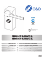
1
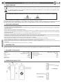
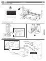
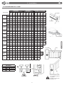
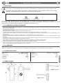
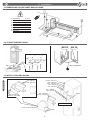
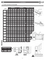
UNAC
ASSOCIAZIONE COSTRUTTORI
DI INFISSI MOTORIZZATI E AUTOMATISMI
PER SERRAMENTI IN GENERE
NIGHT&DAY.6
NIGHT&DAY.8
Barriera automatica
IT
Automatic barrier EN
Barrière automatique FR
Automatische Schranke DE
Barrera automática ES
Istruzioni per installazione uso e manutenzione
Instructions for installation, use and maintenance
Instructions d’installation et d’entretien
Installations, Gebrauchs und Wartungsanleitungen
Instrucciones para la instalación, el uso y el mantenimiento
O&O S.r.l.
Via Europa, 2 - 42015 Correggio (RE) Italy
Tel. +39 0522 740111 - Fax +39 0522 631290
Internet: www.oeo.it - E-mail: [email protected]
AZIENDA CERTIFICATA UNI EN ISO 9001:2008
COMPANY WITH QUALITY SYSTEM CERTIFIED UNI EN ISO 9001:2008
Società soggetta ad attività di direzione e coordinamento di BFT S.p.A.
Company subject to management and coordination activities by BFT S.p.A.
DICHIARAZIONE “CE” DI CONFORMITA’
“CE” DECLARATION OF CONFORMITY
Il costruttore:
O&O Srl
The manufacter:
Indirizzo:
Address:
Via Europa 2 - 42015 Correggio (RE)
DICHIARA CHE IL SEGUENTE APPARATO
DECLARES THAT THE FOLLOWING EQUIPMENT
Descrizione:
Description:
Barriera elettromeccanica automatica
Automatic electromechanical barriers
Modello - Model:
NIGHT&DAY.3
NIGHT&DAY.SPEED
NIGHT&DAY.DD3
NIGHT&DAY.5
NIGHT&DAY.5 XT
NIGHT&DAY.6
NIGHT&DAY.8
-Risulta conforme con quanto previsto dalle seguenti Direttive Comunitarie, comprese le ultime modifiche e con la legislazione nazionale
di recepimento:
Is in conformity with the provisions of the following Community Directives, including the latest modifications and with the assimilating national
legislation:
2004/108/CEE; 93/68/CEE ( EN61000-6-3 (2003); EN61000-6-2 (2003))
Compatibilità Elettromagnetica • Electromagnetic Compatibility
2006/95/CEE; 93/68/CEE ( EN60204-1 (2006))
Bassa tensione • Low voltage
99/5/CEE ( ETSI EN 301 489-3 (2002) + ETSI EN 301 498-1 (2005); ETSI EN 300 220-2 (2006))
Apparecchiatura radio • Radio set
2006/42/CEE ( EN60204-1 (2006))
Direttiva macchine • Machinery directive
L’apparato è stato testato con la centralina elettronica CSB-BR (N&D.3 - N&D.5 - N&D.6 - N&D.8), ARX.DD3 (N&D.DD3), CSB-SP
(N&D.SPEED) e CSB-XT (N&D.5 XT) nella configurazione tipica di installazione.
The equipment has been tested with the electronic control unit CSB-BR (N&D.3 - N&D.5 - N&D.6 - N&D.8), ARX.DD3 (N&D.DD3), CSB-SP
(N&D.SPEED) and CSB-XT (N&D.5 XT) in the typical installation configuration.
Il Rappresentante legale - The legal Representative
Stefano Valzania
ver.6
Correggio, 15/01/13
Indice
2.
3.
Installazione
2.1 Nota cavi..................................................... pag. 5
2.2 Fissaggio struttura...................................... pag. 5
2.3 Installazione barra...................................... pag. 5
2.4
2.5
2.6
2.7
Allineamento barra...................................... pag. 6
Manovra manuale....................................... pag. 6
Optionals..................................................... pag. 6
Equilibratura barra...................................... pag. 7
Uso e manutenzione
3.1 Sicurezza generale..................................... pag. 8
3.2 Avvertenze.................................................. pag. 8
3.3 Uso.............................................................. pag. 8
3.4 Manutenzione ordinaria.............................. pag. 8
ITALIANO
1. Informazioni generali
1.1 Introduzione................................................. pag. 4
1.2 Sicurezza generale..................................... pag. 4
1.3 Generalità.................................................... pag. 4
1.4 Dati tecnici.................................................. pag. 4
1.5 Dimensioni di ingombro.............................. pag. 4
Index
General information
1.1 Introduction.................................................. pag. 9
1.2 General safety............................................ pag. 9
1.3 General....................................................... pag. 9
1.4 Technical specification................................ pag. 9
1.5 Overall dimensions..................................... pag. 9
2.
Installation
2.1 Cable note.................................................. pag.10
2.2 Fixing the structure..................................... pag.10
2.3 Instal the arm.............................................. pag.10
3.
2.4
2.5
2.6
2.7
Align the arm.............................................. pag.11
Manual manoeuvre..................................... pag.11
Optionals..................................................... pag.11
Balancing the arm...................................... pag.12
Use and maintenance
3.1 General safety............................................ pag.13
3.2 Warnings..................................................... pag.13
3.3 Use.............................................................. pag.13
3.4 Routine maintenance.................................. pag.13
ENGLISH
1.
Index
2.
Installations
2.1 Connexion cables....................................... pag.15
2.2 Fixation structure........................................ pag.15
2.3 Installation de la lisse................................. pag.15
3.
2.4
2.5
2.6
2.7
Alignement de la lisse................................ pag.16
Manoeuvre manuelle.................................. pag.16
Optionals..................................................... pag.16
Equilibrage de la lisse................................ pag.17
Utilisation et maintenance
3.1 Sécurité générale........................................ pag.18
3.2 Avertissements............................................ pag.18
3.3 Utilisation..................................................... pag.18
3.4 Routine maintenance.................................. pag.18
FRANÇAIS
1. Informtion generales
1.1 avant-propos............................................... pag.14
1.2 Securite generale........................................ pag.14
1.3 Generalities................................................. pag.14
1.4 Données techniques................................... pag.14
1.5 Dimensions hors-tout.................................. pag.14
Verzeichnis
2.
Installation
2.1 Bemerkung zu den kabel anschlüssen...... pag.20
2.2 Strukturbefestigung..................................... pag.20
2.3 Installation des baums................................ pag.20
3.
2.4
2.5
2.6
2.7
Die schranke ausrichten............................. pag.21
Manuelles manövrieren............................... pag.21
Optionals..................................................... pag.21
Ausbilancierung des baumes..................... pag.22
Gebrauchs und Wartungsanleitungen
3.1 Allgemeine sicherheit.................................. pag.23
3.2 Hinweise...................................................... pag.23
3.3 Betrieb......................................................... pag.23
3.4 Ordentliche wartung.................................... pag.23
DEUTSCH
1. Allgemeine informationen
1.1 Einleitung.................................................... pag.19
1.2 Allgemeine sicherheitshinweise.................. pag.19
1.3 Allgemeines................................................. pag.19
1.4 Technische daten........................................ pag.19
1.5 Abmessungen............................................. pag.19
Índice
2.
Instalación
2.1 Nota cables................................................. pag.25
2.2 Fijación estructura...................................... pag.25
2.3 Instalación de la barra................................ pag.25
3.
3
2.4
2.5
2.6
2.7
Alinear la barra........................................... pag.26
Maniobra manual........................................ pag.26
Optionals..................................................... pag.26
Equilibrado de la barra............................... pag.27
Uso y mantenimiento
3.1 Seguridad general....................................... pag.28
3.2 Advertencias................................................ pag.28
3.3 Uso.............................................................. pag.28
3.4 Mantenimiento ordinario............................. pag.28
ESPAÑOL
1. Informaciones generales
1.1 Introducción................................................. pag.24
1.2 Seguridad general....................................... pag.24
1.3 Generalidad................................................. pag.24
1.4 Datos técnicos............................................ pag.24
1.5 Medidas....................................................... pag.24
IT
1. Informazioni generali
1.1 INTRODUZIONE
ITALIANO
Leggere attentamente il libretto prima di installare il prodotto, utilizzarlo e prima di eseguire manutenzione ordinaria o straordinaria.
Le indicazioni precedute da questo simbolo contengono informazioni di particolare importanza, il loro mancato rispetto
può comportare la perdita della garanzia contrattuale.
LE OPERAZIONI CHE EFFETTUATE IN MODO NON CORRETTO POSSONO PRESENTARE RISCHI SONO INDICATE CON I SIMBOLI:
FOLGORAZIONE
SCHIACCIAMENTO
Il libretto di INSTALLAZIONE USO E MANUTENZIONE è destinato agli installatori, agli utilizzatori ed agli operatori della manutenzione.
La Ditta non è responsabile per danni arrecati a persone, animali o cose dovuti ad applicazioni che superano i limiti indicati nella scheda
tecnica allegata o dall’uso diverso da quello per cui il prodotto è stato progettato.
1.2 SICUREZZA GENERALE
• Smaltire i materiali di imballo (plastica, cartone, polistirolo, ecc.) secondo quanto previsto dalle norme vigenti. Non lasciare buste di nylon e polistirolo a
portata dei bambini.
• La Ditta declina qualsiasi responsabilità derivante dall’uso improprio o diverso da quello per cui è destinato ed indicato nella presente documentazione.
• Non installare il prodotto in atmosfera esplosiva.
• Togliere l’alimentazione elettrica, prima di qualsiasi intervento sull’impianto. Scollegare anche eventuali batterie tampone se presenti.
• Prevedere sulla rete di alimentazione dell’automazione, un interruttore o un magnetotermico onnipolare con distanza di apertura dei contatti uguale o superiore
a 3,5 mm.
• Verificare che a monte della rete di alimentazione, vi sia un interruttore differenziale con soglia da 0,03A.
• Applicare tutti i dispositivi di sicurezza (fotocellule, coste sensibili, ecc.) necessari a proteggere l’area da pericoli di schiacciamento, convogliamento, cesoiamento, secondo ed in conformità alle direttive e norme tecniche applicabili.
• La Ditta declina ogni responsabilità ai fini della sicurezza e del buon funzionamento dell’automazione se vengono impiegati componenti di altri produttori.
• Usare esclusivamente parti originali per qualsiasi manutenzione o riparazione.
• Non eseguire alcuna modifica ai componenti dell’automazione se non espressamente autorizzata dalla Ditta.
• Istruire l’utilizzatore dell’impianto per quanto riguarda i sistemi di comando applicati e l’esecuzione dell’apertura manuale in caso di emergenza.
• Non permettere a persone e bambini di sostare nell’area d’azione dell’automazione.
• Non lasciare radiocomandi o altri dispositivi di comando alla portata dei bambini onde evitare azionamenti involontari dell’automazione.
• Tutto quello che non è espressamente previsto in queste istruzioni, non è permesso.
1.3 GENERALITÀ
La barriera automatica elettromeccanica NIGHT&DAY6-8 è stata progettata per gestire passaggi con luce fino a 8 metri nel rispetto delle normative
europee. Adatta ad un utilizzo di tipo industriale è la soluzione ideale per la gestione del traffico veicolare.
1.4 DATI TECNICI
Lunghezza barra....................................................4÷6.4 m (N&D.6) 6.5÷8 m (N&D.8)
Temp. di esercizio.......................................................................................... -30 +60°C
Manovre in 24h........................................................................................................ 2000
Grado di protezione................................................................................................ IP 65
Peso.................................................................................................................... ~110 kg
Alimentazione.............................................................................. 230Vac ±10% 50/60Hz
Motore............................................................................ 230Vac 900RPM 14uF 0.11kW
Potenza assorbita................................................................................................... 300W
Centralina........................................................................................................... CSB-BR
Sicurezza all’urto................................................................................................Reverser
Tempo di apertura........................................................................................................ 8s
1.5 DIMENSIONI D’INGOMBRO
590
170
360
60
400
950
1155
Barriera DESTRA
Barriera SINISTRA
4
IT
2. Installazione
2.1 NOTA CAVI
ITALIANO
6
1)
2)
3)
4)
5)
6)
6)
7)
Linea Monofase Fotocellula Trasmittente
Fotocellula Ricevente
Lampeggiante
Selettore a chiave
Ricevente
Antenna
Spirale magnetica
2 x 1,5 + T
2 x 0,5
4 x 0,5
2 x 0,5
3 x 0,5
4 x 0,5
RG58
5
3
7
1
2
4
2.2 FISSAGGIO STRUTTURA
CH 13
CH 19
300
300
360
400
Ø80
Non fornito
500
600
400
2.3 INSTALLAZIONE BARRA
M8 - DIN 985
Ø8 - UNI 6592
M10x80 - UNI 5737
Ø10 - UNI 6592
16x60 - UNI 6873
M10 - DIN 985
Ø10 - UNI 6592
Ø10 - UNI6592
M10 - DIN 985
Ø8 - UNI 6592
M8x20 - UNI 5739
Ø10 - UNI 6592
M10x25 - UNI 5739
M6x20
SERRARE 50 Nm
Rimuovere la pellicola protettiva
M6x20
5
IT
2. Installazione
ITALIANO
2.4 ALLINEAMENTO BARRA
• Collegare elettricamente la centralina CSB-BR
• Infilare un pezzo di barra di circa 1 metro nel portabarra
• Dare il comando “START” per posizionare il portabarra
“START” in posizione orizzontale
• Tirare la barra verso il basso per aiutare il riduttore a
vincere la forza della molla pretarata
• Installare la barra e regolare il portabarra
Portabarra regolabile
PER ALLINEARE LA BARRA ALLA PAVIMENTAZIONE STRADALE
AGIRE SUL PORTABARRA REGOLABILE.
NON MODIFICARE LA POSIZIONE DEI FINECORSA GIA’ PRETARATI
2.5 MANOVRA MANUALE
Prima di effettuare qualsiasi intervento sull’impianto togliere l’alimentazione elettrica.
Sbloccaggio manuale
EFFETTUARE SOLO CON BARRA MONTATA
2.6 OPTIONALS
FINECORSA SUPPLEMENTARI
6
IT
2. Installazione
2.7 EQUILIBRATURA DELLA BARRA
NIGHT&DAY 8
NIGHT&DAY 8 + KIT DOUBLE
4000 4500 5000 5500 6000 6500 7000 7500 8000
6500 7000 7500 8000
Molla
B+B
B+B
C
C
C+B
C+C
C+C
C+D
C+D
C+C
C+D
C+D
D+D
A (mm)
125
125
125
95
125
125
110
120
100
115
125
105
115
Molla
B+B
B+B
C
B+C
B+C
C+C
C+D
C+D
D+D
C+D
C+D
D+D
D+D
A (mm)
125
95
95
120
95
110
115
100
105
120
105
110
95
Molla
B+B
B+B
C
B+C
B+C
C+C
C+D
D+D
D+D
C+D
D+D
D+D
D+D
A (mm)
125
85
85
115
85
100
105
110
95
115
120
100
85
Molla
B+B
C
B+C
B+C
C+C
C+D
C+D
D+D
D+D
C+D
C+D
D+D
D+D
A (mm)
100
95
120
95
120
110
90
95
80
100
80
85
70
Molla
B+B
B+B
B+B
B+C
B+C
C+C
C+C
C+D
D+D
C+C
C+D
D+D
D+D
A (mm)
125
115
80
125
110
120
100
110
115
105
115
120
105
Molla
BL-LARGE
+ KIT-LIGHT
+ PP
A (mm)
B+B
C
C
B+C
B+C
C+C
C+D
D+D
D+D
C+D
C+D
D+D
D+D
125
115
85
115
85
100
110
115
95
115
95
105
90
Molla
BL-LARGE
+ KIT-LIGHT
+ KIT-GOM A (mm)
C
C
C
B+C
C+C
C+D
C+D
D+D
D+D
C+D
D+D
D+D
D+D
125
115
80
105
125
120
100
100
80
105
110
95
75
C
C
B+C
B+C
C+C
C+D
D+D
D+D
D+D
D+D
D+D
D+D
D+D
125
85
115
85
115
105
110
85
70
115
95
80
65
Molla
C
C
B+C
B+C
C+C
C+D
D+D
D+D
D+D
D+D
D+D
D+D
A (mm)
125
100
120
90
120
105
110
90
70
115
100
80
Molla
C
B+C
B+C
C+C
C+C
D+D
D+D
D+D
D+D
D+D
D+D
A (mm)
110
125
100
125
100
115
95
75
75
105
90
C
C
B+C
C+C
C+C
D+D
D+D
D+D
D+D
D+D
D+D
D+D
125
90
115
125
110
125
105
80
80
110
90
75
C
B+C
B+C
C+C
C+C
D+D
D+D
D+D
D+D
D+D
D+D
105
125
95
120
95
110
90
75
90
100
80
BL-LARGE
BL-LARGE
+ PP
BL-LARGE
+ KIT-GOM
BL-LARGE
+ KIT-GOM
+ PP
BL-LARGE
+ KIT-LIGHT
BL-LARGE
Molla
+ KIT-LIGHT
+ KIT-GOM
A (mm)
+ PP
BL-LARGE
+ RS/A
BL-LARGE
+ RS/A
+ PP
Molla
BL-LARGE
+ RS/A
+ KIT-LIGHT A (mm)
BL-LARGE
Molla
+ RS/A
+ KIT-LIGHT
A (mm)
+ PP
MOLLE
Molla
Spring
ø filo
ø wire
Codice
Code
B
C
D
ø7,5
ø9,0
ø9,5
024129
024128
024155
KIT-LIGHT
ITALIANO
NIGHT&DAY 6
Taratura molle
118
KIT-GOM
96
KIT-DOUBLE
BL-LARGE
RS/A
PP
A
45°
CH19
Non appesantire la barra applicando altri accessori.
Controllare che la barra sia
equilibrata a ~45°.
7
IT
3. Uso e manutenzione
ITALIANO
3.1 SICUREZZA GENERALE
• La barriera e’ ad uso esclusivamente veicolare, segnalare e delimitare tramite apposito cartello eventuali passaggi pedonali.
• Tenere bambini, persone e cose fuori dal raggio d’azione dell’automazione, in particolare durante il funzionamento.
• Si consiglia, per ragioni di sicurezza e nel rispetto delle normative vigenti, di utilizzare l’apposita centralina di comando CSB-BR.
• L’installazione deve essere eseguita seguendo le prescrizioni contenute nel foglio allegato “AVVERTENZE GENERALI PER LA SICUREZZA”.
• I collegamenti elettrici devono essere effettuati nel rispetto delle disposizioni legislative vigenti.
•L’installatore deve istruire l’utilizzatore sul corretto funzionamento dell’automatismo, sulla manovra manuale d’emergenza e sui possibili rischi durante il
funzionamento.
•Eseguire l’analisi dei rischi prendendo opportuni provvedimenti per eliminarli, come prescritto dalla direttiva macchine 2006/42/CEE, installando i dispositivi
di sicurezza.
•Prima di effettuare qualsiasi intervento sull’impianto togliere l’alimentazione elettrica mediante un sezionatore.
3.2 AVVERTENZE
Il buon funzionamento dell’automazione è garantito solo se vengono rispettate i dati riportati in questo manuale. La Ditta non risponde dei
danni causati dall’inosservanza delle norme di installazione e delle indicazioni riportate in questo manuale.
Le descrizioni e le illustrazioni del presente manuale non sono impegnative. Lasciando inalterate le caratteristiche essenziali del prodotto, la
Ditta si riserva di apportare in qualunque momento le modifiche che essa ritiene convenienti per migliorare tecnicamente, costruttivamente
e commercialmente il prodotto, senza impegnarsi ad aggiornare la presente pubblicazione.
3.3 USO
•Seguire tassativamente le indicazioni contenute nel foglio allegato “AVVERTENZE GENERALI PER LA SICUREZZA”.
•In caso di manovra manuale seguire le indicazioni descritte al punto 2.5.
•Consultare il manuale d’installazione e uso della centralina CSB-BR.
3.4 MANUTENZIONE ORDINARIA (OGNI SEI MESI)
• La manutenzione deve essere eseguita solo da personale qualificato.
• Controllare lo stato della struttura della barriera.
• Controllare lo stato del serraggio barra.
• Controllare lo stato della molla, della catena e dei relativi ancoraggi.
• Controllare l’equilibratura della barra.
• Controllare che a finecorsa la barra sia orizzontale e/o verticale
• Verificare il funzionamento della manovra di emergenza.
• Verificare il funzionamento della centralina e dei dispositivi di sicurezza
8
EN
1. General information
1.1 INTRODUCTION
Please read it carefully before installing the appliance, before using it and before routine or extraordinary maintenance work.
The notices preceded by this symbol provide important information, the non-compliance with such instructions voids the
manufacturer’s guarantee.
OPERATIONS THAT, IF NOT CARRIED OUT CORRECTLY, CAN BE RISKY, ARE INDICATED WITH THE FOLLOWING SYMBOLS
ELECTROCUTION
CRUSHING
The INSTALLATION, USE AND MAINTENANCE handbook is for installers, users and maintenance engineers
The Company is not liable for injury to people or animals or damage to things in the case of applications that exceed the limits specified
on the enclosed technical data sheet or by a use different from what the appliance has been designed.
1.2 GENERAL SAFETY
ENGLISH
• Scrap packing materials (plastic, cardboard, polystyrene etc) according to the provisions set out by current standards. Keep nylon or polystyrene bags
out of children’s reach.
• The Company declines all responsibility for any consequences resulting from improper use of the product, or use which is different from that expected
and specified in the present documentation.
• Do not install the product in explosive atmosphere.
• Disconnect the electrical power supply before carrying out any work on the installation. Also disconnect any buffer batteries, if fitted.
• Fit an omnipolar or magnetothermal switch on the mains power supply, having a contact opening distance equal to or greater than 3,5 mm.
• Check that a differential switch with a 0,03A threshold is fitted just before the power supply mains.
• Fit all the safety devices (photocells, electric edges etc.) which are needed to protect the area from any danger caused by squashing, conveying and
shearing, according to and in compliance with the applicable directives and technical standards.
• The Company declines all responsibility with respect to the automation safety and correct operation when other manufacturer’s components are used.
• Only use original parts for any maintenance or repair operation.
• Do not modify the automation components, unless explicitly authorised by the Company.
• Instruct the product user about the control systems provided and the manual opening operation in case of emergency.
• Do not allow persons or children to remain in the automation operation area.
• Keep radio control or other control devices out of children’s reach, in order to avoid unintentional automation activation.
• Anything which is not expressly provided for in the present instructions, is not allowed.
1.3 GENERAL
The automatic electromechanical barrier NIGHT&DAY6-8 is designed to control passage openings up to 8 metres wide in compliance with European
standards. It is suitable for industrial applications and it is the ideal solution for managing vehicle traffic.
1.4 TECHNICAL SPECIFICATIONS
Arm length.................................................................4÷6.4m (N&D.6) 6.5÷8m (N&D.8)
Working temp................................................................................................. -30 +60°C
Manoeuvres in 24h.................................................................................................. 2000
Protection level....................................................................................................... IP 65
Weight................................................................................................................. ~110 kg
Power.......................................................................................... 230Vac ±10% 50/60Hz
Motor.............................................................................. 230Vac 900RPM 14uF 0.11kW
Absorbed power...................................................................................................... 300W
Control unit......................................................................................................... CSB-BR
Impact safety......................................................................................................Reverser
Opening time................................................................................................................ 8s
1.5 OVERALL DIMENSIONS
590
170
360
60
400
950
1155
RIGHT barrier
LEFT barrier
9
EN
2. Installation
2.1 CABLE NOTE
6
1)
2)
3)
4)
5)
6)
6)
7)
Single-phase line Transmitter photocell Receiver photocell
Flashing light Key selector
Receiver Antenna
Magnetic coil
2 x 1,5 + E
2 x 0,5
4 x 0,5
2 x 0,5
3 x 0,5
4 x 0,5
RG58
5
3
7
ENGLISH
1
2
4
2.2 FIXING THE STRUCTURE
CH 13
CH 19
300
300
360
400
Ø80
Not supplied
500
600
400
2.3 INSTALL THE ARM
M8 - DIN 985
Ø8 - UNI 6592
M10x80 - UNI 5737
Ø10 - UNI 6592
16x60 - UNI 6873
M10 - DIN 985
Ø10 - UNI 6592
Ø10 - UNI6592
M10 - DIN 985
Ø10 - UNI 6592
M10x25 - UNI 5739
Ø8 - UNI 6592
M8x20 - UNI 5739
M6x20
TIGHTEN 50 Nm
Remove the protective film
M6x20
10
EN
2. Installation
2.4 ALIGN THE ARM
“START”
•Electrically connect the control unit
•Insert about 1 metre of the arm in the holder
•Give the “START” command to position the arm
holder horizontally
•Pull the arm down to help the reducer counteract
the force of the pre-calibrated spring
• Install the arm and adjust the holder
USE THE ADJUSTABLE ARM HOLDER TO ALIGN
THE ARM WITH THE ROAD.
DO NOT CHANGE THE POSITION OF THE LIMIT
SWITCHES AS THEY ARE ALREADY ADJUSTED.
2.5 MANUAL MANOEUVRE
Always disconnect the electricity before attempting any work on the system
Releasing the barrier
WITH MOUNTED BOOM ONLY
2.6 OPTIONALS
ADDITIONAL LIMIT SWITCH
11
ENGLISH
Adjustable arm holder
EN
2. Installation
2.7 BALANCING THE ARM
NIGHT&DAY 6
Springs calibration
NIGHT&DAY 8 + KIT DOUBLE
4000 4500 5000 5500 6000 6500 7000 7500 8000
6500 7000 7500 8000
Spring
B+B
B+B
C
C
C+B
C+C
C+C
C+D
C+D
C+C
C+D
C+D
D+D
A (mm)
125
125
125
95
125
125
110
120
100
115
125
105
115
Spring
B+B
B+B
C
B+C
B+C
C+C
C+D
C+D
D+D
C+D
C+D
D+D
D+D
A (mm)
125
95
95
120
95
110
115
100
105
120
105
110
95
Spring
B+B
B+B
C
B+C
B+C
C+C
C+D
D+D
D+D
C+D
D+D
D+D
D+D
A (mm)
125
85
85
115
85
100
105
110
95
115
120
100
85
Spring
B+B
C
B+C
B+C
C+C
C+D
C+D
D+D
D+D
C+D
C+D
D+D
D+D
A (mm)
100
95
120
95
120
110
90
95
80
100
80
85
70
Spring
B+B
B+B
B+B
B+C
B+C
C+C
C+C
C+D
D+D
C+C
C+D
D+D
D+D
A (mm)
125
115
80
125
110
120
100
110
115
105
115
120
105
Spring
BL-LARGE
+ KIT-LIGHT
+ PP
A (mm)
B+B
C
C
B+C
B+C
C+C
C+D
D+D
D+D
C+D
C+D
D+D
D+D
125
115
85
115
85
100
110
115
95
115
95
105
90
Spring
BL-LARGE
+ KIT-LIGHT
+ KIT-GOM A (mm)
C
C
C
B+C
C+C
C+D
C+D
D+D
D+D
C+D
D+D
D+D
D+D
125
115
80
105
125
120
100
100
80
105
110
95
75
C
C
B+C
B+C
C+C
C+D
D+D
D+D
D+D
D+D
D+D
D+D
D+D
125
85
115
85
115
105
110
85
70
115
95
80
65
Spring
C
C
B+C
B+C
C+C
C+D
D+D
D+D
D+D
D+D
D+D
D+D
A (mm)
125
100
120
90
120
105
110
90
70
115
100
80
Spring
C
B+C
B+C
C+C
C+C
D+D
D+D
D+D
D+D
D+D
D+D
A (mm)
110
125
100
125
100
115
95
75
75
105
90
C
C
B+C
C+C
C+C
D+D
D+D
D+D
D+D
D+D
D+D
D+D
125
90
115
125
110
125
105
80
80
110
90
75
C
B+C
B+C
C+C
C+C
D+D
D+D
D+D
D+D
D+D
D+D
105
125
95
120
95
110
90
75
90
100
80
BL-LARGE
BL-LARGE
+ PP
BL-LARGE
+ KIT-GOM
ENGLISH
NIGHT&DAY 8
BL-LARGE
+ KIT-GOM
+ PP
BL-LARGE
+ KIT-LIGHT
BL-LARGE
Spring
+ KIT-LIGHT
+ KIT-GOM
A (mm)
+ PP
BL-LARGE
+ RS/A
BL-LARGE
+ RS/A
+ PP
Spring
BL-LARGE
+ RS/A
+ KIT-LIGHT A (mm)
BL-LARGE
Spring
+ RS/A
+ KIT-LIGHT
A (mm)
+ PP
SPRINGS
Spring
ø wire
Code
B
C
D
ø7,5
ø9,0
ø9,5
024129
024128
024155
KIT-LIGHT
118
KIT-GOM
96
KIT-DOUBLE
BL-LARGE
RS/A
PP
A
45°
CH19
Do not weigh the arm down by applying
other accessories.
Check that the arm is balanced at ~45°.
12
3. Use and maintenance
EN
3.1 GENERAL SAFETY
• The barrier is designed exclusively for vehicles traffic; report and delimit any walkways through a special sign.
• Keep adults, children and property out of range of the automated system, especially while it is operating.
• For safety reasons and to comply with current standards, we recommend using the CSB-BR control unit.
• To install follow the instructions given in the enclosed “GENERAL INSTRUCTIONS FOR SAFETY” sheet.
• All electrical connections must be done in compliance with current laws.
• The installer must instruct the user on how to use the automatism correctly, on the manual emergency manoeuvre and on the possible risks during operation.
• Analyse the risks and take all the appropriate measures to eliminate them, as prescribed by the EEC machine directive 2006/42, installing the safety devices.
• Always disconnect the electricity before attempting any work on the system with a lockable cut-off switch.
3.2 WARNINGS
Correct controller operation is only ensured when the data contained in the present manual are observed. The Company is not to be held
responsible for any damage resulting from failure to observe the installation standards and the instructions contained in the present manual.
The descriptions and illustrations contained in the present manual are not binding. The Company reserves the right to make any alterations
deemed appropriate for the technical, manufacturing and commercial improvement of the product, while leaving the essential product features
unchanged, at any time and without undertaking to update the present publication.
•It is essential to follow the instructions given in the enclosed “GENERAL INSTRUCTIONS FOR SAFETY” sheet.
•In the case of a manual manoeuvre, follow the indications described in point 2.5.
•Consult the control unit’s installation and operating manual.
3.4 ROUTINE MAINTENANCE (EVERY 6 MONTHS)
• La manutenzione deve essere eseguita solo da personale qualificato.
• Maintenance must be carried out by qualified personnel only.
• Check the condition of the barrier structure.
• Check tightness of the arm.
• Check the condition of the spring, chain and relative anchorings.
• Check arm balance.
• Check that at the end of travel the arm is horizontal and/or vertical
• Check operation of the emergency manoeuvre.
• Check operation of the control unit and safety devices.
13
ENGLISH
3.3 USE
FR
1. Informations generales
1.1 AVANT-PROPOS
Lisez attentivement cette notice, avant d’installer l’automatisme, de l’utiliser et avant de procéder à son entretien ordinaire ou extraordinaire.
Les indications précédées de ce symbole contiennent des informations importantes, le non-respect de ces indications peut
invalider la garantie du constructeur.
LES OPÉRATIONS PRÉSENTANT DES RISQUES SI ELLES NE SONT PAS EFFECTUÉES CORRECTEMENT SONT SIGNALÉES AVEC LES SYMBOLES:
ELECTROCUTION
ECRASEMENT
Cette notice est destinée aux installateurs, aux utilisateurs et aux techniciens chargés de l’entretien.
La Société décline toute responsabilité en cas de dégâts à des personnes, animaux ou biens provoqués par des applications dépassant
les limites prévues dans la fiche technique jointe ou par un usage différent de celui pour lequel l’automatisme a été conçu.
• Eliminer les matériaux d’emballage (plastique, carton, polystyrène etc.) selon les prescriptions des normes en vigueur. Ne pas laisser des enveloppes
en nylon et polystyrène à la portée des enfants.
• La Société décline toute responsabilité dérivée d’une utilisation impropre ou différente de celle à laquelle le produit a été destiné et qui est indiquée dans
cette documentation.
• Ne pas installer le produit dans une atmosphère explosive.
• Couper l’alimentation électrique avant d’effectuer n’importe quelle intervention sur l’installation. Débrancher aussi les éventuelles batteries de secours.
• Prévoir sur la ligne d’alimentation de la motorisation un interrupteur ou un magnétothermique omnipolaire avec distance d’ouverture des contacts égale
ou supérieure à 3,5 mm.
• Vérifier qu’en amont de la ligne d’alimentation il y a un interrupteur différentiel avec seuil de 0,03A.
• Appliquer tous les dispositifs de sécurité (cellules photoélectriques, barres palpeuses etc.) nécessaires à protéger la zone des dangers d’écrasement,
d’entraînement, de cisaillement, selon et conformément aux directives et aux normes techniques applicables.
• La Société décline toute responsabilité en matière de sécurité et de bon fonctionnement de la motorisation si des composants d’autres producteurs sont utilisés.
• Utiliser exclusivement des pièces originales pour n’importe quel entretien ou réparation.
• Ne pas effectuer des modifications aux composants de la motorisation si non expressément autorisées par la Société.
• Informer l’utilisateur de l’installation sur les systèmes de commande appliqués et sur l’exécution de l’ouverture manuelle en cas d’urgence.
• Ne pas permettre à des personnes et à des enfants de stationner dans la zone d’action de la motorisation.
• Ne pas laisser des radio commandes ou d’autres dispositifs de commande à portée des enfants afin d’éviter des actionnements involontaires de la
motorisation.
• Tout ce qui n’est pas expressément prévu dans ces instructions, est interdit.
1.3 GENERALITES
La lisse automatique électromécanique NIGHT&DAY6-8 a été conçue pour gérer les passages jusqu’à une hauteur de 8m dans le respect de la
législation européenne. Est la solution idéale pour contrôler le trafic routier. Adaptée à une utilisation de type industrielle.
1.4 DONNÉES TECHNIQUES
Longueur de la lisse............................................... 4÷6.4m (N&D.6) 6.5÷8m (N&D.8)
Température d’exercice.................................................................................. -30 +60°C
Nombre de manoeuvres en 24h............................................................................. 2000
Indice de protection................................................................................................ IP 65
Alimentation................................................................................. 230Vac ±10% 50/60Hz
Moteur............................................................................ 230Vac 900RPM 14uF 0.11kW
Puissance absorbée................................................................................................ 300W
Centrale.............................................................................................................. CSB-BR
Securite au choc................................................................................................Reverser
Delai d’ouverture.......................................................................................................... 8s
Poids................................................................................................................... ~110 kg
1.5 DIMENSIONS HORS-TOUT
590
170
360
60
400
Lisse DROITE
950
1155
FRANÇAIS
1.2 SECURITE GENERALE
Lisse GAUCHE
14
FR
2. Installation
2.1 CONNEXION CABLES
6
1)
2)
3)
4)
5)
6)
6)
7)
Ligne monophasée Photocellule émettrice
Photocellule réceptrice
Clignotant Sélecteur à clé
Récepteur
Antenne
Spirale magnétique
2 x 1,5 + T
2 x 0,5
4 x 0,5
2 x 0,5
3 x 0,5
4 x 0,5
RG58
5
3
7
1
2
4
2.2 FIXATION STRUCTURE
CH 19
CH 13
300
FRANÇAIS
300
360
400
Ø80
Non fourni
500
600
400
2.3 INSTALLATION DE LA LISSE
M8 - DIN 985
Ø8 - UNI 6592
M10x80 - UNI 5737
Ø10 - UNI 6592
16x60 - UNI 6873
M10 - DIN 985
Ø10 - UNI 6592
Ø10 - UNI6592
M10 - DIN 985
Ø10 - UNI 6592
M10x25 - UNI 5739
Ø8 - UNI 6592
M8x20 - UNI 5739
M6x20
SERRER 50 Nm
Retirer le film protecteur
M6x20
15
FR
2. Installation
2.4 ALIGNEMENT DE LA LISSE
“START”
• Branchez le groupe CSB-BR à l’alimentation électrique
• Enfilez une longueur de lisse de 1 mètre environ dans le
support de lisse
• Actionnez la commande “START” pour placer le support de
lisse en position horizontale
• Tirez la lisse vers le bas de telle sorte que le réducteur puisse
exercer une force supérieure à la résistance opposée par
le ressort préréglé;
• Installez la lisse et réglez le support de lisse.
Support de lisse réglable
POUR ALIGNER LA LISSE PAR RAPPORT À LA CHAUSSÉE,
INTERVENIR SUR LE SUPPORT DE LISSE RÉGLABLE.
NE PAS MODIFIER LA POSITION DES FINS DE COURSE
PRÉRÉGLÉES.
FRANÇAIS
2.5 MANOEUVRE MANUELLE
Coupez l’arrivée de courant électrique avant toute intervention sur l’automatisme
Déblocage de la lisse
SEULEMENT AVEC LA LISSE MONTÉ
2.6 OPTIONALS
MICRO-INTERRUPTEUR ADDITIONEL
16
FR
2. Installation
2.7 EQUILIBRAGE DE LA LISSE
NIGHT&DAY 6
Ressort tarage
NIGHT&DAY 8
NIGHT&DAY 8 + KIT DOUBLE
6500 7000 7500 8000
Ressort
B+B
B+B
C
C
C+B
C+C
C+C
C+D
C+D
C+C
C+D
C+D
D+D
A (mm)
125
125
125
95
125
125
110
120
100
115
125
105
115
Ressort
B+B
B+B
C
B+C
B+C
C+C
C+D
C+D
D+D
C+D
C+D
D+D
D+D
A (mm)
125
95
95
120
95
110
115
100
105
120
105
110
95
Ressort
B+B
B+B
C
B+C
B+C
C+C
C+D
D+D
D+D
C+D
D+D
D+D
D+D
A (mm)
125
85
85
115
85
100
105
110
95
115
120
100
85
Ressort
B+B
C
B+C
B+C
C+C
C+D
C+D
D+D
D+D
C+D
C+D
D+D
D+D
A (mm)
100
95
120
95
120
110
90
95
80
100
80
85
70
Ressort
B+B
B+B
B+B
B+C
B+C
C+C
C+C
C+D
D+D
C+C
C+D
D+D
D+D
A (mm)
125
115
80
125
110
120
100
110
115
105
115
120
105
BL-LARGE Ressort
+ KIT-LIGHT
+ PP
A (mm)
B+B
C
C
B+C
B+C
C+C
C+D
D+D
D+D
C+D
C+D
D+D
D+D
125
115
85
115
85
100
110
115
95
115
95
105
90
BL-LARGE Ressort
+ KIT-LIGHT
+ KIT-GOM A (mm)
C
C
C
B+C
C+C
C+D
C+D
D+D
D+D
C+D
D+D
D+D
D+D
125
115
80
105
125
120
100
100
80
105
110
95
75
C
C
B+C
B+C
C+C
C+D
D+D
D+D
D+D
D+D
D+D
D+D
D+D
125
85
115
85
115
105
110
85
70
115
95
80
65
Ressort
C
C
B+C
B+C
C+C
C+D
D+D
D+D
D+D
D+D
D+D
D+D
A (mm)
125
100
120
90
120
105
110
90
70
115
100
80
Ressort
C
B+C
B+C
C+C
C+C
D+D
D+D
D+D
D+D
D+D
D+D
A (mm)
110
125
100
125
100
115
95
75
75
105
90
C
C
B+C
C+C
C+C
D+D
D+D
D+D
D+D
D+D
D+D
D+D
125
90
115
125
110
125
105
80
80
110
90
75
C
B+C
B+C
C+C
C+C
D+D
D+D
D+D
D+D
D+D
D+D
105
125
95
120
95
110
90
75
90
100
80
BL-LARGE
BL-LARGE
+ PP
BL-LARGE
+ KIT-GOM
BL-LARGE
+ KIT-GOM
+ PP
BL-LARGE
+ KIT-LIGHT
BL-LARGE Ressort
+ KIT-LIGHT
+ KIT-GOM
A (mm)
+ PP
BL-LARGE
+ RS/A
BL-LARGE
+ RS/A
+ PP
BL-LARGE Ressort
+ RS/A
+ KIT-LIGHT A (mm)
BL-LARGE Ressort
+ RS/A
+ KIT-LIGHT
A (mm)
+ PP
RESSORT
Ressort
ø Fil
Code
B
C
D
ø7,5
ø9,0
ø9,5
024129
024128
024155
KIT-LIGHT
118
KIT-GOM
96
KIT-DOUBLE
BL-LARGE
RS/A
PP
A
45°
CH19
Ne pas alourdire la lisse
en y appliqant d’autres
accessoires.
S’assurer que la lisse est
équilibrée à ~45°.
17
FRANÇAIS
4000 4500 5000 5500 6000 6500 7000 7500 8000
FR
3. Utilisation et maintenance
3.1 SÉCURITÉ GÉNÉRALE
• La barrière est conçu exclusivement pour les véhicules; signaler et délimiter par un signe spécial les allées piétonnes.
• Tenez les enfants, les personnes et les objets à l’écart du rayon d’action de l’automatisation, en particulier pendant son fonctionnement.
• Pour des raisons de sécurité et d’observation de la législation en vigueur, il est conseillé d’utiliser la centrale de commande CSB-BR.
• La pose doit s’effectuer selon les prescriptions reportées sur la feuille jointe “REGLES GENERALES DE SECURITE”.
•Les branchements électriques doivent être conformes à la législation en vigueur en la matière.
•L’installateur doit informer l’utilisateur sur le fonctionnement de l’automatisme, sur la manœuvre manuelle d’arrêt d’urgence et sur les risques liés au
fonctionnement.
•L’analyse des risques implique la mise sur pied de mesures destinées à éliminer lesdits risques comme le prévoit la directive machines 2006/42/CEE,
en installant les dispositifs de sécurité.
•Coupez l’arrivée de courant électrique avant toute intervention sur l’automatisme avec un interrupteur verrouillable.
3.2 AVERTISSEMENTS
Le bon fonctionnement de l’actionneur n’est assuré que si les données fournies dans ce manuel sont respectées. Le constructeur ne répond
pas pour les dommages provoqués par le non respect des normes d’installation et des indications fournies dans ce manuel.
Les descriptions et les figures de ce manuel n’engagent pas le constructeur. En laissant inaltérées les caractéristiques essentielles du produit, la Société se réserve le droit d’apporter à n’importe quel moment les modifications qu’elle juge opportunes pour améliorer le produit
du point de vue technique, commercial et de construction, sans s’engager à mettre à jour cette publication.
3.3 UTILISATION
• Suivez scrupuleusement les prescriptions reportées sur la feuille jointe “REGLES GENERALES DE SECURITE”.
• En cas de manœuvre manuelle, suivez les indications décrites au paragraphe 2.5.
• Consulter le manuel d’installation et d’utilisation de la centrale.
FRANÇAIS
3.4 ROUTINE MAINTENANCE (TOUS LES 6 MOIS)
• L’entretien doit être effectué seulement par un personnel qualifié.
• Contrôlez la structure de la lisse.
• Contrôlez le serrage de la lisse.
• Contrôlez l’état du ressort, de la chaîne et des fixations correspondantes.
• Contrôlez l’équilibrage de la lisse.
• Contrôlez l’horizontalité et/ou la verticalité de la lisse en fin de course.
• Vérifiez le fonctionnement de la manœuvre d’urgence.
• Vérifiez le fonctionnement de la centrale et des dispositifs de sécurité.
18
DE
1. Allgemeine informationen
1.1 EINLEITUNG
Das Handbuch ist vor der Installation des Produkts sowie vor der ordentlichen und außerordentlichen Wartung sorgfältig zu lesen.
Die Angaben, denen dieses Symbol vorangestellt ist, enthalten Informationen zu allen möglichen Themen von bes onderer
Bedeutung, ihre Nichtbeachtung kann zum Verlust der vertraglichen Garantie führen.
WENN DIE DURCH FOLGENDE SYMBOLE GEKENNZEICHNETEN EINGRIFFE NICHT KORREKT DURCHGEFÜHRT WERDEN, KANN ES ZU GEFAHRSITUATIONEN KOMMEN:
STROMSCHLAG
QUETSCHUNG
Das INSTALLATIONS, BETRIEBS UND WARTUNGSHANDBUCH ist für die Installateure, Anwender und Wartungsfachmänner bestimmt.
Der Hersteller haftet nicht für Personen, Tier oder Sachschäden, die auf eine unsachgemäße Anwendung des Produkts sowie auf das
Überschreiten der im technischen Blatt angegebenen Grenzwerte zurückzuführen sind.
1.2 ALLGEMEINE SICHERHEITSHINWEISE
• Verpackungsmaterialien (Plastik, Karton, Polystyrol u. a.) sind nach den einschlägigen Vorschriften zu entsorgen. Keine Nylon-oder Polystyroltüten in Reichweite von Kindern liegenlassen.
• Der Hersteller lehnt jede Verantwortung für Folgen ab, die durch den unsachgemäßen oder nicht bestimmungsgemäßen, weil in dieser Doku-mentation nicht
genannten Gebrauch entstehen.
• Die Anlage darf nicht in explosionsgefährdeter Atmosphäre installiert werden.
• Vor jedem Eingriff an der Anlage die Stromversorgung unterbrechen. Auch Pufferbatterien abklemmen, falls vorhanden.
• Versehen Sie die Versorgungsleitung der Anlage mit einem Schalter oder allpoligen magnetthermischen Schutzschalter mit einem Kontaktabstand von mindestens 3,5 mm.
• Der Versorgungsleitung muß ein Fehlerstromschutzschalter mit einer Schwelle von 0,03A vorgeschaltet sein.
• Alle Sicherheitsvorrichtungen (Fotozellen, Sicherheitsleisten u. a.) anbringen, die verhindern, daß sich im Torbereich jemand quetscht, schneidet oder mitgerissen wird.
• Der Hersteller lehnt jede Verantwortung für die Sicherheit und die Funkti onstüchtigkeit der Anlage ab, wenn Komponenten anderer Produzenten verwendet werden.
• Für Wartungen und Reparaturen ausschließlich Originalteile verwenden.
• Keine Umbauten an Anlagenkomponenten vornehmen, wenn sie nicht ausdrücklich vom Hersteller genehmigt wurden.
• Weisen Sie den Anlagennutzer in die vorhandenen Steuerungssysteme und die manuelle Toröffnung im Notfall ein.
• Kindern oder Erwachsenen ist es nicht gestattet, im Aktionsbereich der Anlage zu verweilen.
• Keine Fernbedienungen oder andere Steuerungsvorrichtungen in Reichweite von Kindern liegenlassen. Sie könnten die Anlage versehentlich in Gang setzen.
• Alles, was nicht ausdrücklich in dieser Anleitung genannt ist, ist untersagt.
1.3 ALLGEMEINES
Die automatisch elektromechanische Schranke NIGHT&DAY6-8 wurde für Durch und Einfahrten mit einer Breite von maximal 8 Metern entwickelt und
entspricht den EU-Normen. Es ist die ideale Lösung zum Verwalten des Straßenverkehrs. Für den industriellen Gebrauch geeignet.
1.4 TECHNISCHE DATEN
1.5 ABMESSUNGEN
DEUTSCH
Baumbreite.............................................................. 4÷6.4m (N&D.6) 6.5÷8m (N&D.8)
Betriebstemperatur......................................................................................... -30 +60°C
Manöver in 24 std.................................................................................................... 2000
Schutzgrad.............................................................................................................. IP 65
Gewicht............................................................................................................... ~110 kg
Stromversorgung......................................................................... 230Vac ±10% 50/60Hz
Motor.............................................................................. 230Vac 900RPM 14uF 0.11kW
Leistungsaufnahme................................................................................................. 300W
Steuereinheit...................................................................................................... CSB-BR
Stossicherheit.....................................................................................................Reverser
Öffnungsdauer.............................................................................................................. 8s
590
170
360
60
400
950
1155
RECHTE Schranke
LINKE Schranke
19
DE
2. Installation
2.1 BEMERKUNG ZU DEN KABEL ANSCHLÜSSEN
6
1)
2)
3)
4)
5)
6)
6)
7)
Einphasenleitung Senderfotozelle
Empfängerfotozelle
Blinkleuchte
Schlüsselschalter
Empfänger
Antenne
Magnetspirale
2 x 1,5 + E
2 x 0,5
4 x 0,5
2 x 0,5
3 x 0,5
4 x 0,5
RG58
5
3
7
1
2
4
2.2 STRUKTURBEFESTIGUNG
CH 13
CH 19
300
300
360
400
Ø80
Nicht mitgeliefert
500
600
400
2.3 INSTALLATION DES BAUMS
DEUTSCH
M8 - DIN 985
Ø8 - UNI 6592
M10x80 - UNI 5737
Ø10 - UNI 6592
16x60 - UNI 6873
M10 - DIN 985
Ø10 - UNI 6592
Ø10 - UNI6592
M10 - DIN 985
Ø8 - UNI 6592
M8x20 - UNI 5739
Ø10 - UNI 6592
M10x25 - UNI 5739
M6x20
FESTZIEHEN 50 Nm
Entfernen Sie die Schutzfilm
M6x20
20
2. Installation
DE
2.4 DIE SCHRANKE AUSRICHTEN
“START”
• Die Steuereinheit elektrisch anschließen
• Die Schranke mit einer Länge von ca. 1 m in die Schrankenhalterung einschieben.
• Den Befehl „START“ eingeben, um Die Schrankenhalterung in die
waagrechte Position bringen
• Die Schranke nach unten ziehen, damit das Untersetzungsgetriebe
die Kraft der vorgeeichten Feder leichter überwinden kann.
• Die Schranke montieren und die Schrankenhalterung einstellen
Verstellbare Schrankenhalterung
ZUM AUSRICHTEN DER SCHRANKE MIT DEM STRASSEBELAG IST AUF DIE VERSTELLBARE SCHRANKENHALTERUNG
EINZUWIRKEN.
DIE POSITION DER BEREITS VORGEEICHTEN ENDSCHALTER NICHT ÄNDERN.
2.5 MANUELLES MANÖVRIEREN
Vor jeglichen Eingriffen an der Anlage ist die Stromversorgung zu unterbrechen.
NUR MIT MONTIERTEM BAUM AUSFÜHREN
2.6 OPTIONALS
ENDSCHALTER ZUSÄTZLICH
21
DEUTSCH
Schranke entsperren
DE
2. Installation
2.7 AUSBILANCIERUNG DES BAUMES
NIGHT&DAY 6
Federn
Kalibrierung
NIGHT&DAY 8 + KIT DOUBLE
4000 4500 5000 5500 6000 6500 7000 7500 8000
6500 7000 7500 8000
Federn
B+B
B+B
C
C
C+B
C+C
C+C
C+D
C+D
C+C
C+D
C+D
D+D
A (mm)
125
125
125
95
125
125
110
120
100
115
125
105
115
Federn
B+B
B+B
C
B+C
B+C
C+C
C+D
C+D
D+D
C+D
C+D
D+D
D+D
A (mm)
125
95
95
120
95
110
115
100
105
120
105
110
95
Federn
B+B
B+B
C
B+C
B+C
C+C
C+D
D+D
D+D
C+D
D+D
D+D
D+D
A (mm)
125
85
85
115
85
100
105
110
95
115
120
100
85
Federn
B+B
C
B+C
B+C
C+C
C+D
C+D
D+D
D+D
C+D
C+D
D+D
D+D
A (mm)
100
95
120
95
120
110
90
95
80
100
80
85
70
Federn
B+B
B+B
B+B
B+C
B+C
C+C
C+C
C+D
D+D
C+C
C+D
D+D
D+D
A (mm)
125
115
80
125
110
120
100
110
115
105
115
120
105
BL-LARGE Federn
+ KIT-LIGHT
+ PP
A (mm)
B+B
C
C
B+C
B+C
C+C
C+D
D+D
D+D
C+D
C+D
D+D
D+D
125
115
85
115
85
100
110
115
95
115
95
105
90
BL-LARGE Federn
+ KIT-LIGHT
+ KIT-GOM A (mm)
C
C
C
B+C
C+C
C+D
C+D
D+D
D+D
C+D
D+D
D+D
D+D
125
115
80
105
125
120
100
100
80
105
110
95
75
C
C
B+C
B+C
C+C
C+D
D+D
D+D
D+D
D+D
D+D
D+D
D+D
125
85
115
85
115
105
110
85
70
115
95
80
65
Federn
C
C
B+C
B+C
C+C
C+D
D+D
D+D
D+D
D+D
D+D
D+D
A (mm)
125
100
120
90
120
105
110
90
70
115
100
80
Federn
C
B+C
B+C
C+C
C+C
D+D
D+D
D+D
D+D
D+D
D+D
A (mm)
110
125
100
125
100
115
95
75
75
105
90
C
C
B+C
C+C
C+C
D+D
D+D
D+D
D+D
D+D
D+D
D+D
125
90
115
125
110
125
105
80
80
110
90
75
C
B+C
B+C
C+C
C+C
D+D
D+D
D+D
D+D
D+D
D+D
105
125
95
120
95
110
90
75
90
100
80
BL-LARGE
BL-LARGE
+ PP
BL-LARGE
+ KIT-GOM
BL-LARGE
+ KIT-GOM
+ PP
BL-LARGE
+ KIT-LIGHT
BL-LARGE Federn
+ KIT-LIGHT
+ KIT-GOM
A (mm)
+ PP
BL-LARGE
+ RS/A
BL-LARGE
+ RS/A
+ PP
BL-LARGE Federn
+ RS/A
+ KIT-LIGHT A (mm)
DEUTSCH
NIGHT&DAY 8
BL-LARGE Federn
+ RS/A
+ KIT-LIGHT
A (mm)
+ PP
Ø Federn
Federn
ø Drahtes
Code
B
C
D
ø7,5
ø9,0
ø9,5
024129
024128
024155
KIT-LIGHT
118
KIT-GOM
96
KIT-DOUBLE
BL-LARGE
RS/A
PP
A
45°
CH19
Den Baum nicht durch die Installation von weiterem Zubehör belasten.
Überprüfen, dass die Schranke in
der ~45°-Stellung ausgeglichen ist.
22
3. Gebrauchs und Wartungsanleitungen
DE
3.1 ALLGEMEINE SICHERHEIT
• Die Schranke ist ausschließlich für den Fahrzeugverkehr vorgesehen; ein eventueller Fußgängerverkehr ist durch ein geeignetes Schild auszuweisen bzw.
einzuschränken.
• Halten Sie Kinder, Personen und Sachen aus dem Wirkungsbereich der Automatisierung fern, vor allem während des Betriebs • Aus Sicherheitsgründen und zum Einhalten der anwendbaren Gesetze wird empfohlen, die spezielle Steuereinheit von CSB-BR zu verwenden.
• Bei der Installation sind die im beiliegenden Blatt “ALLGEMEINE SICHERHEITSHINWEISE” enthaltenen Vorschriften zu befolgen.
• Beim Anschluss an die Stromversorgung sind die geltenden Gesetze zu befolgen.
• Der Installateur hat den Anwender bezüglich des korrekten Betriebs des Automatismus, der manuellen Bedienung bei Störungen und Notfällen sowie bezüglich
der möglichen Gefahren während des Betriebs zu unterrichten.
•Es ist eine Gefahrenanalyse durchzuführen und es sind geeignete Maßnahmen zum Eliminieren der Gefahren zu treffen, wie von der Maschinenrichtlinie
2006/42/EWG vorgeschrieben, wobei auch der Schub einreguliert und die erforderlichen Sicherheitsvorrichtungen installiert werden müssen.
•Vor jeglichen Eingriffen an der Anlage ist die Stromversorgung mit einen Schlüssel-Trennschalter zu unterbrechen.
3.2 HINWEISE
Der einwandfreie Betrieb des Antriebes ist nur dann garantiert, wenn die Angaben aus diesem Handbuch beachtet werden. Der Hersteller haftet nicht
für Schäden, die durch Mißachtung der Installationsanweisungen und der Angaben aus diesem Handbuch entstehen.
Die Beschreibungen und bildlichen Darstellungen in diesem Handbuch sind unverbindlich. Der Hersteller behält sich - ohne auch zur Aktualisierung
dieser Unterlagen verpflichtet zu sein - jederzeit vor, Änderungen vornehmen, wenn er diese für technische oder bauliche Verbesserungen als notwendig erachtet und die wesentlichen Produkteigenschaften unverändert bleiben.
3.3 BETRIEB
•Die in dem beigestellten Blatt “ALLGEMEINE SICHERHEITSVOR-SCHRIFTEN” enthaltenen Anleitungen sind strikt zu befolgen.
•Beim manuellen Manövrieren sind die unter Punkt 2.5 beschriebenen Anleitungen zu beachten.
•Die Installations und Bedienungsanleitungen der Steuereinheit CSB-BR nachschlagen.
3.4 ORDENTLICHE WARTUNG (ALLE 6 MONATE)
• Die Wartung hat ausschließlich durch Fachpersonal zu erfolgen.
• Zustand der Schrankenstruktur überprüfen.
• Kontrollieren, dass der Baum korrekt befetsigt ist.
• Zustand der Feder, der Kette und der entsprechenden Verankerungen überprüfen.
• Ausbilancierung des Baumes überprüfen.
• Kontrollieren, dass der Baum am Endanschlag waagerecht oder senkrecht ist.
• Funktionstüchtigkeit des Notmanövers überprüfen..
• Funktionstüchtigkeit der Steuereinheit und der Sicherheitsvorrichtungen überprüfen.
DEUTSCH
23
ES
1. Informaciones generales
1.1 INTRODUCCIÓN
Leer detenidamente el folleto antes de instalar el producto, utilizarlo y efectuar el mantenimiento ordinario o extraordinario.
Las indicaciones precedidas por este símbolo contienen informaciones sobre cualquier asunto de importancia particular, no
respetarlas puede comportar la perdida de la garantía contractual.
LAS OPERACIONES QUE, SI NO SON EFECTUADAS CORRECTAMENTE, PUEDEN CONLLEVAR RIESGOS, VIENEN INDICADAS CON LOS SÍMBOLOS:
ELECTROCUCIÓN
APLASTAMIENTO
El folleto de INSTALACIÓN, USO Y MANTENIMIENTO se destina a instaladores, usuarios y operadores de mantenimiento.
La Empresa no es responsable de daños causados a personas, animales o cosas, debidos a aplicaciones que superen los límites indicados
en la ficha técnica adjunta o debidos a utilización diferente de aquella apra la cual el producto fue proyectado.
1.2 SEGURIDAD GENERAL
• Eliminar los materiales de embalaje (plástico, cartón, poliestireno, etc.) según lo previsto por las normas vigentes. No dejar bolsas de nylon o poliestireno al
alcance de los niños.
• La Empresa declina toda responsabilidad que derive del uso impropio del producto o de un uso distinto de aquél para el que está destinado y que aparece
indicado en la presente documentación.
• No instalar el producto en atmósfera explosiva.
• Cortar el suministro de corriente antes de efectuar cualquier intervención en la instalación. Desconectar también eventuales baterías tampón, si las hay.
• Prever, en la red de alimentación del automatismo, un interruptor o un magnetotérmico omnipolar con una distancia de abertura de los contactos igual o
superior a 3,5 mm.
• Verificar que, antes de la red de alimentación, haya un interruptor diferencial con un umbral de 0,03A.
• Aplicar todos los dispositivos de seguridad (fotocélulas, barras sensibles, etc.) necesarios para proteger el área del peligro de aplastamiento, transporte o
cizallado, de conformidad con las directivas y normas técnicas vigentes.
• La Empresa declina toda responsabilidad, a efectos de la seguridad y del buen funcionamiento del automatismo, si se emplean componentes de otros fabricantes.
• Usar exclusivamente partes originales al realizar cualquier operación de mantenimiento o reparación.
• No modificar ningún componente del automatismo si antes no se ha sido expresamente autorizado por la Empresa.
• Instruir al usuario del equipo sobre los sistemas de mando aplicados y la ejecución de la apertura manual en caso de emergencia.
• No permitir que personas o niños estacionen en el campo de acción del automatismo.
• No dejar radiomandos u otros dispositivos de mando al alcance de los niños, para evitar el accionamiento involuntario del automatismo.
• Todo lo que no está expresamente previsto en estas instrucciones no está permitido.
1.3 GENERALIDAD
La barrera automática electromecánica NIGHT&DAY6-8 ha sido diseñada para controlar pasos con ancho de hasta 8 metros, según las normas
europeas. Es la solución ideal para la gestión del tráfico de vehiculos. Es apta para una utilización de tipo industrial
1.4 DATOS TÉCNICOS
Longitud barra......................................................... 4÷6.4m (N&D.6) 6.5÷8m (N&D.8)
Temp. de operación....................................................................................... -30 +60°C
Maniobras en 24h.................................................................................................... 2000
Grado de protección............................................................................................... IP 65
Peso.................................................................................................................... ~110 kg
Alimentación................................................................................ 230Vac ±10% 50/60Hz
Motor.............................................................................. 230Vac 900RPM 14uF 0.11kW
Potencia absorbida................................................................................................. 300W
Centralita............................................................................................................ CSB-BR
Seguridad al choque..........................................................................................Reverser
Tiempo de apertura..................................................................................................... 8s
1.5 MEDIDAS
590
170
360
60
400
950
1155
ESPAÑOL
Barrera DERECHA
Barrera IZQUIERDA
24
ES
2. Instalación
2.1 NOTA CABLES
6
1)
2)
3)
4)
5)
6)
6)
7)
Línea monofásica Fotocélula transmisor
Fotocélula receptor
Indicador intermitente
Selector de llave
Receptor
Antena
Espiral magnética
2 x 1,5 + T
2 x 0,5
4 x 0,5
2 x 0,5
3 x 0,5
4 x 0,5
RG58
5
3
7
1
2
4
2.2 FIJACIÓN ESTRUCTURA
CH 19
CH 13
300
300
360
400
Ø80
No suministrada
500
600
400
2.3 INSTALACIÓN DE LA BARRA
M8 - DIN 985
Ø8 - UNI 6592
M10x80 - UNI 5737
Ø10 - UNI 6592
16x60 - UNI 6873
M10 - DIN 985
Ø10 - UNI 6592
Ø10 - UNI6592
M10 - DIN 985
Ø8 - UNI 6592
M8x20 - UNI 5739
Ø10 - UNI 6592
M10x25 - UNI 5739
M6x20
Quite la película protectora
M6x20
25
ESPAÑOL
APRETAR 50 Nm
ES
2. Instalación
2.4 ALINEAR LA BARRA
“START”
• Conectar eléctricamente la centralita CSB-BR
•Insertar un trozo de barra de aproximadamente 1 metro
en el portabarra
•Dar el comando “START” para colocar el portabarra en
posición horizontal
•Tirar de la barra hacia abajo para ayudar al reductor a
vencer la fuerza del muelle calibrado de antemano
• Instalar la barra y ajustar el portabarra
portabarra regulable
PARA ALINEAR LA BARRA CON LA CALZADA, ACTUAR SOBRE
EL PORTABARRA REGULABLE.
NO MODIFICAR LA POSICIÓN DE LOS FINALES DE CARRERA
YA PREAJUSTADOS.
2.5 MANIOBRA MANUAL
Antes de cualquier operación en la instalación, cortar la alimentación eléctrica.
Desbloqueo barrera
HACER SÓLO CON BARRA MONTADA
ESPAÑOL
2.6 OPTIONALS
FIN DE CARRERA ADICIONAL
26
ES
2. Instalación
2.7 EQUILIBRADO DE LA BARRA
Resorte
calibración
NIGHT&DAY 6
NIGHT&DAY 8
NIGHT&DAY 8 + KIT DOUBLE
4000 4500 5000 5500 6000 6500 7000 7500 8000
6500 7000 7500 8000
Resorte
B+B
B+B
C
C
C+B
C+C
C+C
C+D
C+D
C+C
C+D
C+D
D+D
A (mm)
125
125
125
95
125
125
110
120
100
115
125
105
115
Resorte
B+B
B+B
C
B+C
B+C
C+C
C+D
C+D
D+D
C+D
C+D
D+D
D+D
A (mm)
125
95
95
120
95
110
115
100
105
120
105
110
95
Resorte
B+B
B+B
C
B+C
B+C
C+C
C+D
D+D
D+D
C+D
D+D
D+D
D+D
A (mm)
125
85
85
115
85
100
105
110
95
115
120
100
85
Resorte
B+B
C
B+C
B+C
C+C
C+D
C+D
D+D
D+D
C+D
C+D
D+D
D+D
A (mm)
100
95
120
95
120
110
90
95
80
100
80
85
70
Resorte
B+B
B+B
B+B
B+C
B+C
C+C
C+C
C+D
D+D
C+C
C+D
D+D
D+D
A (mm)
125
115
80
125
110
120
100
110
115
105
115
120
105
BL-LARGE Resorte
+ KIT-LIGHT
+ PP
A (mm)
B+B
C
C
B+C
B+C
C+C
C+D
D+D
D+D
C+D
C+D
D+D
D+D
125
115
85
115
85
100
110
115
95
115
95
105
90
BL-LARGE Resorte
+ KIT-LIGHT
+ KIT-GOM A (mm)
C
C
C
B+C
C+C
C+D
C+D
D+D
D+D
C+D
D+D
D+D
D+D
125
115
80
105
125
120
100
100
80
105
110
95
75
C
C
B+C
B+C
C+C
C+D
D+D
D+D
D+D
D+D
D+D
D+D
D+D
125
85
115
85
115
105
110
85
70
115
95
80
65
Resorte
C
C
B+C
B+C
C+C
C+D
D+D
D+D
D+D
D+D
D+D
D+D
A (mm)
125
100
120
90
120
105
110
90
70
115
100
80
Resorte
C
B+C
B+C
C+C
C+C
D+D
D+D
D+D
D+D
D+D
D+D
A (mm)
110
125
100
125
100
115
95
75
75
105
90
C
C
B+C
C+C
C+C
D+D
D+D
D+D
D+D
D+D
D+D
D+D
125
90
115
125
110
125
105
80
80
110
90
75
C
B+C
B+C
C+C
C+C
D+D
D+D
D+D
D+D
D+D
D+D
105
125
95
120
95
110
90
75
90
100
80
BL-LARGE
BL-LARGE
+ PP
BL-LARGE
+ KIT-GOM
BL-LARGE
+ KIT-GOM
+ PP
BL-LARGE
+ KIT-LIGHT
BL-LARGE Resorte
+ KIT-LIGHT
+ KIT-GOM
A (mm)
+ PP
BL-LARGE
+ RS/A
BL-LARGE
+ RS/A
+ PP
BL-LARGE Resorte
+ RS/A
+ KIT-LIGHT A (mm)
BL-LARGE Resorte
+ RS/A
+ KIT-LIGHT
A (mm)
+ PP
Resorte
Resorte
ø hilo
Código
B
C
D
ø7,5
ø9,0
ø9,5
024129
024128
024155
KIT-LIGHT
118
KIT-GOM
96
KIT-DOUBLE
BL-LARGE
RS/A
PP
A
45°
No aumentar el peso de la barra
poniendo otros accesorios.
Comprobar que la barra esté
equilibrada a ~45°.
27
ESPAÑOL
CH19
ES
2. Uso y mantenimiento
3.1 SEGURIDAD GENERAL
• La barrera está diseñada exclusivamente para el passaje vehicular, informar y delimitar el pasaje peatonal a través de una señal especial.
• Mantener a niños, personas y cosas fuera del radio de acción de la automatización, especialmente durante su funcionamiento.
• Por razones de seguridad y para respetar las normas vigentes se aconseja utilizar la correspondiente centralita de control CSB-BR.
• La instalación debe efectuarse siguiendo las prescripciones presentadas en la hoja adjunta“ADVERTENCIAS GENERALES PARA LA SEGURIDAD”.
• Las conexiones eléctricas deben efectuarse cumpliendo las disposiciones de ley vigentes.
• El instalador debe instruir al usuario sobre el funcionamiento correcto del automatismo, maniobra manual de emergencia y posibles riesgos durante el
funcionamiento.
•Efectuar el análisis de riesgos tomando las oportunas medidas para eliminarlos, como prescrito por la directiva máquina 2006/42/CEE, instalando los
dispositivos de seguridad.
•Antes de cualquier operación en la instalación, cortar la alimentación eléctrica con un interruptor seccionador.
3.2 ADVERTENCIAS
El buen funcionamiento del operador resulta garantizado únicamente si se respetan los datos contenidos en este manual de instrucciones. La
empresa no responde de los daños causados por el incumplimiento de las normas de instalación y de las indicaciones contenidas en este manual.
Las descripciones y las ilustraciones del presente manual tienen un carácter puramente indicativo. Dejando inalteradas las características esenciales del producto, la Empresa se reserva la posibilidad de aportar, en cualquier momento, las modificaciones que considere convenientes para
mejorar técnica, constructiva y comercialmente el producto, sin la obligación de poner al día esta publicación.
3.3 USO
• Seguir tajantemente las indicaciones presentadas en la hoja adjunta “ADVERTENCIAS GENERALES PARA LA SEGURIDAD”.
• En caso de maniobra manual seguir las indicaciones del punto 2.5.
• Consultar el manual de instalación y uso de la centralita CSB-BR.
3.4 MANTENIMIENTO ORDINARIO (CADA 6 MESES)
Cod. 035340-A r.005 - 16/05/13
• El mantenimiento debe ser efectuado sólo por personal cualificado.
• Comprobar el estado de la estructura de la barrera.
• Comprobar el estado del apriete de la barra.
• Comprobar el estado del muelle, de la cadena y correspondientes fijaciones.
• Comprobar el equilibrio de la barra.
• Comprobar que a tope de carrera la barra quede horizontal y/o vertical
• Verificar el funcionamiento de la maniobra de emergencia.
• Verificar el funcionamiento de la centralita y de los dispositivos de seguridad.
O&O s.r.l. a socio unico - Via Europa, 2 - 42015 CORREGGIO (RE) Italy
tel. +39 (0)522 740111 - fax +39 (0)522 631290
http://www.oeo.it - email: [email protected]
Società soggetta ad attività di direzione e coordinamento di BFT S.p.a.
Company subject to management and coordination activities by BFT S.p.a.
Société sujette à des activités de direction et de coordination de BFT S.p.a.
Gesellschaft unter der Führung und Koordinierung von BFT S.p.a.
Sociedad sujeta a actividades de dirección y coordinación de BFT S.p.a.
28