1
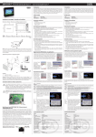
Manuale Tecnico | Technical Manual E-system 2 | Manuale Tecnico | Technical Manual E-system 3 | Manuale Tecnico | Technical Manual E-system Battiscopa filo muro | Flush-to-wall Skirting Boards Tipologie e differenze dei profili: Profile types and differences: 1) Profili per strutture massicce in muratura 1) Profiles for masonry solid structures 2) Profili per strutture a secco (cartongesso, pannelli in legno o altro materiale) 2) Profiles for drywall (plasterboard, wood panels or other materials) Per entrambe le tipologie di profilo esistono varianti di altezza e una sola variante di profondità maggiorata da utilizzare esclusivamente per l’inserimento dei battiscopa in ceramica o piastrella. For both profile types there are different height and only one kind of oversize depth which must be used exclusively for the inserting of tiled skirting boards. al fissaggio finale con degli stop adeguati al tipo di parete. A ogni giunzione o angolo da effettuare, sia interno che esterno, è necessario tagliare il profilo a misura e inserire l’accessorio adatto. (fig. 3-4) fixing. Use proper screw anchor depending of the wall typology. For each joint or internal/external corner profile, customcut the profile and insert the proper accessory. (fig 3-4) Ultimata la posa dei profili, si potrà procedere a intonacare le pareti, avendo particolare accortezza nel rasare perfettamente a filo del bordino in alluminio e non debordare da tale livello per evitare successivi distaccamenti e un risultato estetico non ottimale. (fig. 5-6) Completed the laying of the profiles, plastering the walls giving attention to level it perfectly flush to the aluminum border. Do not overflow the plaster in order to avoid possible future detachment and an imperfect aesthetic result. Tutti i profili sono lunghi 2 metri e, in base al tipo scelto, è necessario utilizzare gli appositi accessori di giunzione, gli angoli esterni o interni o le squadre per gradini al fine di ottenere un risultato tecnico ed estetico ottimale. All profiles have a length of 2 meters and, depending of the chosen type, it is necessary to use the proper junction accessory, internal or external corner profiles or joints for steps in order to obtain an optimal technical and aesthetic result. Per le quote e una corretta installazione dei profili fare sempre riferimento alla direzione lavori e al materiale illustrativo fornito. Making reference to the project manager and to the illustrations provided for dimensions and a correct installation of the profiles. Posa in opera dei profili: Laying the profiles: Prima della posa del pavimento si raccomanda di staccare la pellicola protettiva dal profilo. 1) Profili per strutture massicce in muratura 1) Profiles for masonry solid structures 2) Profili per strutture a secco Il muro grezzo deve essere asciutto e pulito da eventuali residui di calce o altre asperità fino a ottenere una superficie liscia e regolare. The rough wall must be dried and clean from possible traces of lime or others irregularities to obtain a smooth and regular surface. I profili vanno avvitati all’intelaiatura in metallo o legno. Assemblare i profili con i giunti o gli angoli necessari alla porzione di parete interessata. Sgrassare la parte posteriore del profilo e applicare la colla di montaggio. Per evitare un’eccessiva schiumatura del collante si consiglia di pressare il profilo contro la parete, staccarlo brevemente e riposizionarlo in maniera definitiva (fig. 1-2). Considering the part of wall concerned, the profiles must be assembled with the necessary joints or corner profiles. Before applying the foam glue for the installation, clean the profiles back. In order to avoid a glue foaming excess, the profile must be pressed though the wall, unstick it briefly and replace it definitely (fig. 1-2). Quando il collante sarà indurito si potrà procedere Once the glue is hardened, proceed with the final Ad ogni giunzione o angolo da effettuare, sia interno che esterno, è necessario tagliare il profilo a misura e inserire l’accessorio adatto. Ultimata la posa dei profili, si potrà applicare la parete in cartongesso da 12,5 mm posandola direttamente sul bordo di appoggio del profilo e fissandola con le apposite viti autofilettanti. Successivamente si procederà alla stuccatura della parete avendo particolare accortezza nel rasare perfettamente a filo del bordino in alluminio e non debordare da tale livello per evitare successivi distaccamenti e un risultato estetico non ottimale. (fig. 5-6) Remove the protective film from the profile before the floor laying. 2) Profiles for drywall Screwing the profiles to the metallic or wooden framework. For each joint or internal/external corner profile, customcutting the profile and inserting the proper accessory. Completed the laying of the profiles, applying the plasterboard wall (12,5 mm). Laying it directly on the profile support border and fix it with the proper selftapping screw. Filling with filler the wall giving attention to level it perfectly flush to the aluminum border. Do not overflow the filler in order to avoid possible future detachment and an imperfect aesthetic result. (fig. 5-6) 4 | Manuale Tecnico | Technical Manual E-system 5 | Manuale Tecnico | Technical Manual E-system Battiscopa filo muro | Flush-to-wall Skirting Boards SCHEDE TECNICHE | SPECIFICATIONS malta plaster malta grezza | rough plaster Remove the protective film from the profile before the floor laying. malta grezza | rough plaster malta plaster Anche in questo caso prima della posa del pavimento si raccomanda di staccare la pellicola protettiva dal profilo. Fig. 5 - Installazione corretta | Correct installation Fig. 6 - Installazione NON corretta | Incorrect installation M ontaggio dei battiscopa: Skirting boards installation: I battiscopa in legno, o altro materiale, vanno tagliati su misura avendo cura di lasciare una piccola fessura nella parte superiore per evitare la trasmissione dei rumori tra parete e pavimento. In order to avoid the sound transmission between wall and floor, the skirting boards, in wood or other materials, must be custom-cut giving attention to leave a little chink in the upper part of it. Posizionare due strisce di nastro biadesivo nella parte superiore e inferiore del battiscopa e del collante siliconico nella zona centrale, quindi premere con forza il battiscopa al profilo e farlo aderire perfettamente. Placing two strips of double-side tape on the upper and lower part of the skirting board and the foam glue on the central part of it. Then press firmly the skirting board to the profile in order to let it stick perfectly. 1. P rofili in alluminio per battiscopa in legno Strutture massicce 1. A luminum profiles for wooden skirting boards Solid structures 6 | Manuale Tecnico | Technical Manual E-system 7 | Manuale Tecnico | Technical Manual E-system SCHEDE TECNICHE | SPECIFICATIONS 1. A luminum profiles for wooden skirting boards Solid structures seconda lastra second sheet wooden or matellic frame telaio in metallo oppure in legno 2. A luminium profiles for wooden skirting boards Drywalls 2. P rofili in alluminio per battiscopa in legno Strutture a secco 1. P rofili in alluminio per battiscopa in legno Strutture massicce variabile variable da stuccare fill with filler visible base zoccolino visibile parquet Codice | Code: ES158020 Codice | Code: ES154620 Codice | Code: ES156020 massetto footing altezza variabile: zovvolino visibile da 45mm fino a 120mm variable height: visible base from 45 mm to 120 mm 8 | Manuale Tecnico | Technical Manual E-system 9 | Manuale Tecnico | Technical Manual E-system SCHEDE TECNICHE | SPECIFICATIONS 2. P rofili in alluminio per battiscopa in legno Strutture a secco 2. A luminium profiles for wooden skirting boards Drywalls Codice | Code: ES154621 Codice | Code: ES156021 3. A luminium profile for tiled skirting board - Solid structures 3. P rofilo in alluminio per battiscopa in piastrella o ceramica - Strutture massicce Codice | Code: ES157020 Drawing: art. No. Scale: 1:1 Model C 10171 10 | Manuale Tecnico | Technical Manual E-system 11 | Manuale Tecnico | Technical Manual E-system SCHEDE TECNICHE | SPECIFICATIONS 4. P rofilo in alluminio per battiscopa in piastrella o ceramica - Strutture a secco 4. A luminium profile for tiled skirting board - Drywalls Codice | Code: ES157021 5. C orner profiles and Joints 5. Angolari e giunti Angolare interno | Internal corner Angolare esterno | External corner Giunto | Joint Giunto per gradini | Joint for steps 12 | Manuale Tecnico | Technical Manual E-system 13 | Manuale Tecnico | Technical Manual E-system Porte filo muro | Flush-to-wall doors Tipologie e differenze dei telai: Frame typologies and differences: 1) Telaio porta a spingere 2) Telaio porta a tirare 1) Door frame - push 2) Door frame - pull Entrambe le tipologie di telaio sono adatte all’installazione sia su pareti in muratura che su pareti a secco, in cartongesso o altri materiali. Both frame typologies can be installed on masonry walls or drywalls, plasterboard or other materials. Data la grande varietà di misure disponibili, ogni porta verrà inviata completa del proprio telaio realizzato su misura. Si rende quindi indispensabile al momento dell’ordine specificare il codice di appartenenza seguito dalle misure esatte della porta, dal verso di apertura destro o sinistro e se a spingere o a tirare. Considering the great range of available dimensions, each door is sent with its own costum-cut frame. In the order, for that reason, it is compulsory specify the E-System code of the door with the exact dimension and the opening way of it: push or pull, right or left. Esempio codice per ordine porta laccata bianca da 90x220 destra a spingere: ES950003 90x220 DX S Esempio codice per ordine porta verniciabile da 90x220 sinistra a tirare: ES850003 90x220 SX T Per maggior chiarezza sul corretto verso di apertura vedere figura. Per i codici di appartenenza consultare il catalogo. Example: code for a white lacquered door, 90x220, right to push: ES950003 90x220 R PUSH Example: code for a paintable door, 90x220, left to pull: ES850003 90x220 L PULL In order to better understand the correct opening way, please look at the following picture. For the exact door code, please consult the catalogue. Per i codici di appartenenza consultare il catalogo. For the exact door code, please consult the catalogue. Prima dell’installazione, si consiglia di apporre una numerazione alla porta e al corrispondente telaio, onde evitare ulteriori fasi di ricerca. Una volta prelevato quest’ultimo dalla scatola, si raccomanda di conservare la porte con cura dentro il proprio imballo e riporla in luogo sicuro. It is suggested to identify with the same number the door and its frame before the installation in order to avoid future further researches. Once the frame has been removed from the original box, it is important to preserve the door inside its own package in a safe place. Nell’imballo originale si trova tutto il materiale necessario al completamento dell’installazione. Tutti i componenti, dalle guarnizioni alle cerniere hanno la propria e inequivocabile sede, così come pre assemblate in fabbrica. The original box contains all the material necessary to complete the installation. Every components, from gaskets to hinges, have their own seat as pre-assembled by the manufacturer. Posa in opera dei telai: Frame laying: Il telaio è già assemblato e completo di tutti gli accessori necessari a essere ancorato alla parete, sia in muratura che in cartongesso. E’ fondamentale in ogni caso che il telaio venga installato seguendo le quote indicate dalla direzione lavori. The frame is already assembled and complete with all the accessories needed for the installation on every kind of wall (masonry or plasterboard). The frame must be installed following the dimensions given by the project manager. 14 | Manuale Tecnico | Technical Manual E-system 15 | Manuale Tecnico | Technical Manual E-system Porte filo muro | Flush-to-wall doors 1) Porte su strutture massicce in muratura 1) Doors for masonry solid structures Ultimata la prima fase di fissaggio, si potrà procedere alla posa dell’intonaco sollevando prima la rete e riempiendo bene tutta la superficie sottostante senza creare dei vuoti, in seguito si dovrà adagiare la rete e inglobarla all’intonaco fresco con la passata finale. After the first fixing, proceed with the laying of the plaster lifting the PVC net. Fill carefully all the underlying surface without create vacuums, then lay the PVC net down and incorporate it to the wet plaster with the final coat. E’ molto importante durante la rasatura finale non eccedere con il materiale oltre il filo del bordo in alluminio al fine di ottenere un risultato estetico ottimale e ridurre il rischio di crepature (Fig. 2-3). In order to obtain a perfect aesthetic result and the reduction of crack risk, during the final leveling it is important to not exceed with the material over the aluminum border (Fig. 2-3) fig.3 Telaio per porta a tirare fig.3 Door frame - pull Apertura muro grezzo | Rough wall opening Rete in PVC | PVC Net Intonaco | Plaster Anta da 45mm Shutter 45mm Anta da 50mm | Shutter 50mm Anta da 56mm | Shutter 56mm fig.2 Telaio per porta a spingere fig.2 Door frame -p ush Muro grezzo | Rough wall Staffa di fissaggio Fixing bracket Rete in PVC | PVC Net Intonaco | Plaster 16 | Manuale Tecnico | Technical Manual E-system 17 | Manuale Tecnico | Technical Manual E-system Porte filo muro | Flush-to wall doors fig.5 Telaio per porta a tirare su muro in cartongesso After the first framework fixing, proceed with the laying of the plaster sheet under the PVC net. Lift the net and apply the first filler coat without create vacuums, then lay the PVC net down and incorporate it to the wet filler with the final leveling. Si consiglia di sollevare la rete e apporre la prima passata di stucco per riempire tutti gli spazi, successivamente la rete verrà adagiata alla parete e inglobata allo stucco ancora fresco con la rasatura finale. In order to obtain a perfect aesthetic result and the reduction of crack risk, during the final leveling it is important to not exceed with the material over the aluminum border (Fig- 4-5). Rete in PVC | PVC Net Fig.4 Telaio per porta a spingere su muro in cartongesso fig.4 Door frame - push - Drywalls Primo lato First sheet Montante in metallo / legno Metal/ Wood Doorjamp Apertura muro grezzo | Rough wall opening Stuccare Fill with filler 4,0 Secondo lato | Second sheet 75mm 45 Primo lato First sheet Montante in metallo / legno Metal/ Wood Doorjamp Stuccare Fill with filler staffa di fissaggio Fixing Bracket Cartongesso Plasterboard Secondo lato | Second sheet Stuccare Fill with filler staffa di fissaggio Fixing Bracket Primo lato First sheet Secondo lato | Second sheet Primo lato First sheet 4,0 Cartongesso Plasterboard .45-55mm .50-60mm .56-65mm Rete in PVC | PVC Net Stuccare Fill with filler Secondo lato | Second sheet 75mm E’ molto importante durante la rasatura non eccedere con il materiale oltre il filo del bordo in alluminio al fine di ottenere un risultato estetico ottimale e ridurre il rischio di crepature(Fig. 4-5) Apertura muro grezzo | Rough wall opening 60mm 56mm Ultimata la prima fase di fissaggio all’intelaiatura, si potrà procedere alla posa della lastra di cartongesso infilandola sotto la rete in pvc. fig.5 Door frame - pull - Drywalls 45mm 2) Door for drywalls 50mm 2) Porte su strutture a secco Rete in PVC | PVC Net Anta | Shutter Rete in PVC | PVC Net Anta | Shutter 18 | Manuale Tecnico | Technical Manual E-system 19 | Manuale Tecnico | Technical Manual E-system Touch Panel PC filo muro | Flush-to-wall Touch Panel PC Tipologie e dimensioni: Types and differences: Installazione delle scatole metalliche Metallic boxes installation 1) Touch panel PC 10,4” 2A 12Vcc Cristallo L340xH260mm 2) Touch panel PC 15” 3A 12Vcc Cristallo L410xH330mm 1) Touch panel PC 10,4” 2A 12Vcc Criystal L340xH260mm 2) Touch panel PC 15” 3A 12Vcc Crystal L410xH330mm Dimensioni: Dimension: - Scatola per touch pc 10,4’’ L320xH240xP75mm - Scatola per touch pc 15’’ L380xH310xP80mm - 10,4’’ touch pc box L320xH240xD75mm - 15’’ touch pc box L380xH310xD80mm Touch panel PC fanless, finitura con pannello in vetro temperato effetto specchio, touch capacitivo e audio bidirezionale (altoparlante + microfono). Fanless touch panel PC, tempered crystal screen with mirror coating, sensitivity capacity touch screen and bidirectional audio module (loudspeaker + microphone). • Masonry solid structures Walling up the provided box in order to place the two flanges with their fixing holes on the right and left side. Il touch panel PC è destinato unicamente alla gestione degli impianti domotici attraverso una interfaccia grafica completamente personalizzabile in fase di programmazione, secondo le funzionalità messe a disposizione dall’impianto domotico realizzato, e dal funzionamento semplice ed intuitivo. Trattandosi di un vero e proprio PC dalle notevoli prestazioni è garantita la massima compatibilità con i sistemi di domotica attualmente in commercio. The touch panel PC is only for the managing of home automation systems. It has a graphic interface which is completely customizable during the programming, depending on the functionality available from the home automation system realized, with an easy and intuitive working. • Strutture massicce in muratura Murare la scatola in dotazione in modo che le due flange con i quattro fori di fissaggio del touch panel siano a destra e a sinistra. Dispone di due porte seriali RS232/422 o 485, porta LAN RJ45, uscita VGA per monitor aggiuntivo, porta PS/2 per mouse e tastiera, due porte USB 2.0 e ingresso/uscita audio. The touch panel is an authentic PC, for that reason the compatibility with the home automation systems currently on the market is guaranteed. It has two serial port RS232/422 or 485, LAN port RJ45, VGA port for additional monitor, PS/2 port for mouse and keyboard, two USB 2.0 port and sound input/output. I touch panel PC vengono venduti con installato il solo sistema operativo Windows XP Embedded. Sarà cura dell’installatore e programmatore dell’impianto caricare il software di gestione, le mappe grafiche dell’edificio e le funzioni visibili a monitor secondo specifiche richieste del committente. Touch panel PC are provided only with operating system (Windows XP Embedded). Entrambe le tipologie di touch panel PC, ognuna con la propria scatola da incasso, sono adatte all’installazione sia su pareti in muratura che su pareti in cartongesso. In questo secondo caso è necessario utilizzare l’apposito kit per installazione su cartongesso. Per la corretta installazione delle scatole da incasso e il corretto posizionamento delle tubazioni e cavi elettrici seguire le istruzioni riportate nelle pagine seguenti. Both touch panel PC types, each one with its own embedding box, can be installed on masonry and dry wall. The uploading of software, building graphic maps and functions visible on monitor according to client specific requests, will be realized by technician. A proper kit is required for installation on dry wall. For a correct embedding boxes installation and an appropriate placement of tubes and electrical cable, please follow the present manual. E’ indispensabile curare al massimo la corretta installazione della scatola, e in particolare la messa in bolla in quanto non è possibile regolare l’angolazione del touch panel rispetto alla scatola. E’ indispensabile, inoltre, curare la corretta stuccatura del bordo della cassaforma: il filo della scatola deve essere perfettamente complanare alla parete. Sui lati superiori e laterali della scatola sono predisposti più fori per l’entrata dei tubi e l’eventuale aerazione. Il touch panel è stato progettato per lavorare in ambiente chiuso senza scambio di aria. Tuttavia, se è possibile, in fase di installazione della scatola e dei tubi elettrici, conviene adottare alcuni accorgimenti che consentano un migliore smaltimento del calore prodotto: ad esempio innestare nella scatola dei tubi verticali, possibilmente in alluminio, per far salire l’aria calda . • Strutture a secco Utilizzare l’apposito kit per l’installazione della scatola metallica. Forare il cartongesso secondo le misure della cassaforma da installare (Fig.1). Montare le due squadrette e bloccarle con i dadi dall’interno in posizione intermedia (c’è un’asola di regolazione della posizione a seconda dello spessore del cartongesso: da 6mm a 25mm) (Fig.2). Orientare la cassaforma con la freccia verso l’alto, inserire la It is really important doing a correct installation of the box. Please pay attention to the perfect leveling of the box because it is not possible adjust the touch panel angle in respect to it. It is necessary to plaster properly the box perimeter: wall and box must be perfectly leveled. Holes for the tubes entrance and possible aeration are prepared on the upper part and lateral side of the box. The touch panel is designed to work in close environment without air recirculation. However, if it is possible, during the installation of the box and electrical tubes, could be useful draining the produced heat. For example, inserting in the box vertical tubes, possibly in aluminum, in order to push up the warm air. • Dry wall A proper kit is required for installation on dry wall. Drilling the plasterboard according to the measurement of the box (Fig.1). Installing the two squares. Through provided nuts, fixing them in a middle position of the box inner side (there is a slot to regulate the position depending on the plasterboard depth: from 6mm to 25mm) (Fig.2). Placing the box with the arrow up then insert it in the hole until 20 | Manuale Tecnico | Technical Manual E-system 21 | Manuale Tecnico | Technical Manual E-system Touch Panel PC filo muro | Flush-to-wall Touch Panel PC scatola nel foro fino ad arrivare a battuta con le due squadrette, marcare i punti di fissaggio delle viti e la posizione in verticale delle squadrette (Fig.3). leveling it with the two squares. Making a note of the screw fixing points and of the square vertical position (Fig.3). Rimuovere la scatola dal foro e le squadrette dalla scatola. Posizionare queste ultime dietro al cartongesso secondo i segni e avvitare le viti da cartongesso (Fig.4). Inserire nuovamente la scatola fino ad allinearla con il bordo al cartongesso e ribloccarla con i dadi. Remove the box from the hole and the squares from the box. Place the squares behind the plasterboard according to the notes and screw the plasterboard screws (Fig.4). Insert again the box, level it with the wall and fix it with the nuts. Stuccare sopra le viti e attorno alla scatola. In caso di verniciatura della parete, verniciare anche l’interno della scatola per qualche centimetro. In caso di tappezzeria, farla rientrare nella scatola per qualche centimetro. Connessione della parte touch panel Prima di effettuare le connessioni, ricordarsi che tutte le morsettiere sono sul lato sinistro del touch panel PC, pertanto tenerne conto in fase di intestazione dei cavi. Inoltre è conveniente che il cristallo del touch panel sia rimosso con apposita ventosa, in modo da prevenire eventuali rotture o scheggiature durante il lavoro di connessione. • Collegamento di terra Sul fondo della scatola è presente un collegamento di terra già precablato. Connetterlo all’impianto di terra generale. Questo collegamento è obbligatorio, altrimenti il buon funzionamento del touch screen non è garantito. Rispettare le normative vigenti per la realizzazione del collegamento di terra. • Collegamento alla rete LAN Se richiesto dal progetto, effettuare il collegamento alla rete LAN utilizzando solo cavo CAT.5 e connettore PLUG RJ45 a 8 poli. Filling with filler over the screws and all around the box. In case of painting of the wall, paint also few centimeters of the box inner part. In case of wallpaper, cover also few centimeters of the box inner part. Touch panel connection Before connecting, please remember that the terminal boards are on the left side of the touch panel PC. Keep in mind this information during the cable installation. It is also advised to remove the touch panel crystal using the proper suction cup, in order to avoid possibly damage during the connection. • Ground Connection On the box bottom there is a ground connection already wired. Connecting it to the general ground system. This connection it is compulsory, otherwise the correct functioning of the touch screen is not guaranteed. For the realization of the ground connection, please respect the current regulations. • LAN connection If required by the project, connecting the LAN using only CAT.5 cable and RJ45 plug connector - 8 pins. • Collegamento alla linea seriale RS422/485 Se richiesto, effettuare il collegamento alla linea seriale RS422/485 sulla morsettiera dedicata a 5 poli, secondo il pin-out indicato sull’etichetta: • Serial line RS422/485 Connection If required by the project, connecting the serial line RS422/485 to the 5 pins terminal board, following the pin-out on the label: 1 2 3 4 5 1 2 3 4 5 DCD RXD TXD DTR GND 422RX422RX+ 422TX+ 422TX- 485485+ La morsettiera a vite è sconnettibile: sconnettere il connettore volante, effettuare il cablaggio; al momento del fissaggio del touch panel PC riconnettere e serrare le due viti di bloccaggio. Il touch PC è predisposto di serie per la linea RS422. Su richiesta viene modificato in fabbrica per la linea RS485. • Collegamento alla linea seriale RS232 Se richiesto, effettuare il collegamento alla linea seriale RS232 utilizzando il connettore standard DB9 maschio. • Collegamento alle porte USB Se necessario, effettuare il collegamento alle porte USB 2.0 utilizzando i connettori standard USB. • Collegamento tastiera/mouse Se necessario, collegare una tastiera e/o un mouse al connettore Mini-Din mediante il cavo adattatore a Y in dotazione. • Collegamento all’alimentazione Il touch PC va alimentato con tensione continua a 12 Vdc stabilizzata. Collegare l’alimentazione sulla morsettiera dedicata a 2 poli, secondo il pin-out indicato sull’etichetta: 1 2 POSITIVO NEGATIVO La morsettiera a vite è sconnettibile: sconnettere il connettore volante, effettuare il cablaggio; al momento del fissaggio del touch panel PC riconnettere e serrare le due viti di bloccaggio. DCD RXD TXD DTR GND 422RX422RX+ 422TX+ 422TX- 485485+ The terminal board can be unscrewed: disconnect the detachable connector and wire. Before fixing the touch panel PC, reconnect and screw up the two lock screws. The touch panel PC is compatible for RS422 line. It can be modified by the manufacturer for line RS485 on request. • Serial line RS232 Connection If required by the project, connecting the serial line RS232 by a standard DB9 male connector. • USB port Connection If required, connecting to 2.0 USB port/s by standard USB connector. • Keyboard/mouse Connection If required, connecting a keyboard and/or a mouse to MiniDin connector by the Y-adaptor cable provided. • Power supply Connection The touch panel PC must be supplied by stabilized 12 V Dc. Connecting the power supply to the 2 pin terminal board, following the pin-out on the label: 1 2 POSITIVE NEGATIVE The terminal board can be unscrewed: disconnect the detachable connector and wire. Before fixing the touch panel PC, reconnect and screw up the two lock screws. A power supply polarity inversion damages in a irreversible way the electronic devices of the touch panel PC. 22 | Manuale Tecnico | Technical Manual E-system 23 | Manuale Tecnico | Technical Manual E-system Touch Panel PC filo muro | Flush-to-wall Touch Panel PC Una inversione di polarità sull’alimentazione comporta il danneggiamento degli apparati elettronici presenti nel touch panel PC in modo irreversibile. Installazione del touch panel Accertarsi che il touch panel PC non abbia il frontale di cristallo montato; in caso contrario staccarlo. Inserire il touch PC nella scatola orientandolo con il lato morsettiere a sinistra e bloccarlo con le 4 viti in dotazione. Prima del fissaggio, pulire accuratamente il sensore touch capacitivo e il cristallo dal lato interno con normali detergenti per vetro e panno morbido. Attenzione a non abradere o rigare la vernice posteriore e a non far penetrare liquidi nel touch panel PC. Effettuare la pulizia quando il touch panel non è alimentato. Touch panel installation If the touch panel PC has the crystal installed, please remove it. Place the touch panel with the terminal boards on the left, insert it in the metallic box and lock it with the provided 4 screws. Before fixing, please clean carefully the sensitivity capacity touch screen and the crystal from the inner side. Using a common glass cleaner and a soft cloth. Paying attention to not abrade or scratch the paint and to not let the liquids seep through the touch panel PC. Cleaning when the touch panel is not supplied. Put close the touch panel crystal and position it correctly following the back position of the check pins: place the side with 2 pins down and the side with 1 pin up. Avvicinare il cristallo al touch PC e orientarlo correttamente in base alla posizione posteriore dei perni di fissaggio: porre il lato con 2 perni in basso e il lato con 1 perno in alto. Accertarsi che i perni di fissaggio siano in linea con le relative sedi sul touch panel PC. Quindi esercitare sul cristallo una pressione prima sulla parte inferiore e poi su quella superiore. Far entrare i perni di fissaggio dentro alle sedi corrispondenti fino a sentire gli scatti di blocco. Leveling the crystal check pins to the corresponding touch panel slots. Verificare scrupolosamente che il cristallo sia ben fissato e non ci sia rischio di distacco accidentale. Removing touch panel from the box Smontaggio del touch panel PC dalla scatola Accertarsi di aver tolto l’alimentazione. Per rimuovere il cristallo utilizzare la ventosa fornita in dotazione. Quindi staccare gli altri due perni posti in alto. Rimuovere il corpo interno del touch PC smontando le 4 viti, prestando attenzioni ai fili connessi. Accensione e spegnimento Fornire la tensione di alimentazione a 12 Vdc. Nel momento in cui si fornisce tensione il touch panel PC si Pushing firstly on the bottom crystal part, then on the upper part. The pins must be inserted wholly into the corresponding slots until hearing the lock click. The crystal must be fixed firmly to avoid possible detachments, please check it very carefully. Disconnect the power supply, remove the touch panel crystal using the proper suction cup and detach the other two pins in the upper side. Then remove the entire touch panel PC unscrewing the 4 screws. Please pay attention to the connected wires. Turning On/Off The touch panel starts automatically as soon as it is connected to the power supply (12 V Dc required). Before the connection, it is suggested to complete the installing and fixing operations. The turning off procedures depend avvia automaticamente. E’ preferibile dare alimentazione a installazione e fissaggio ultimati. Le modalità di spegnimento dipendono dal sistema operativo e dal software installato. Dotazione Il touch panel PC viene fornito con il seguente materiale in dotazione: - Cavo a Y doppio PS/2 per collegamento tastiera e mouse; - 4 viti per il fissaggio alla scatola; - 2 Cd con driver di installazione; - Certificato di collaudo; - Manuale di istruzioni per l’installatore. N.B. Il vetro frontale è stato realizzato con un cristallo che ha subito un trattamento termico di tempra in accordo alla normativa UNI EN 12150, che lo rende sicuro nel caso di rottura accidentale, in quanto si scompone in piccolissimi frammenti non taglienti e non pericolosi. La marchiatura “TEMPERED” sul cristallo non è riportata per un fattore estetico. A richiesta il costruttore può fornire un documento comprovante l’avvenuto trattamento. on the operating system and the installed software. Equipment The touch panel PC is provided with the following equipment: - PS/2 Y-adaptor cable for mouse and keyboard connection; - 4 lock screws to fix the box; - 2 Cd with installation driver; - Test certification; - Installation instruction manual. N.B. The frontal glass is realized with a crystal which is processed by temper heat treating according to UNI EN 12150. In case of accidental damages the crystal breaks up itself in small fragments which are neither dangerous nor sharp thanks by the process already described. For an aesthetical purpose, “TEMPERED” mark does not appear on the crystal. The document which proves the authenticity of the treating is available from the manufacturer on request. Eclettis is a brand of [email protected] eclettis.com via Rosciano, 1a 60030 Belvedere Ostrense (An) Italia t. 0039 0731 217038 f. 0039 0731 217039